EP1326307A2 - An electrical contact element for plug-in connectors - Google Patents
An electrical contact element for plug-in connectors Download PDFInfo
- Publication number
- EP1326307A2 EP1326307A2 EP02027004A EP02027004A EP1326307A2 EP 1326307 A2 EP1326307 A2 EP 1326307A2 EP 02027004 A EP02027004 A EP 02027004A EP 02027004 A EP02027004 A EP 02027004A EP 1326307 A2 EP1326307 A2 EP 1326307A2
- Authority
- EP
- European Patent Office
- Prior art keywords
- contact element
- plug
- guide
- bias
- guide portion
- Prior art date
- Legal status (The legal status is an assumption and is not a legal conclusion. Google has not performed a legal analysis and makes no representation as to the accuracy of the status listed.)
- Withdrawn
Links
- 239000002184 metal Substances 0.000 claims abstract description 4
- 238000005452 bending Methods 0.000 claims description 18
- 230000013011 mating Effects 0.000 claims description 18
- 238000010276 construction Methods 0.000 description 5
- 238000004519 manufacturing process Methods 0.000 description 4
- 238000011161 development Methods 0.000 description 3
- 230000018109 developmental process Effects 0.000 description 3
- 238000005259 measurement Methods 0.000 description 2
- 238000004080 punching Methods 0.000 description 2
- 230000004308 accommodation Effects 0.000 description 1
- 238000006073 displacement reaction Methods 0.000 description 1
Images


Classifications
-
- H—ELECTRICITY
- H01—ELECTRIC ELEMENTS
- H01R—ELECTRICALLY-CONDUCTIVE CONNECTIONS; STRUCTURAL ASSOCIATIONS OF A PLURALITY OF MUTUALLY-INSULATED ELECTRICAL CONNECTING ELEMENTS; COUPLING DEVICES; CURRENT COLLECTORS
- H01R13/00—Details of coupling devices of the kinds covered by groups H01R12/70 or H01R24/00 - H01R33/00
- H01R13/02—Contact members
- H01R13/04—Pins or blades for co-operation with sockets
- H01R13/05—Resilient pins or blades
-
- H—ELECTRICITY
- H01—ELECTRIC ELEMENTS
- H01R—ELECTRICALLY-CONDUCTIVE CONNECTIONS; STRUCTURAL ASSOCIATIONS OF A PLURALITY OF MUTUALLY-INSULATED ELECTRICAL CONNECTING ELEMENTS; COUPLING DEVICES; CURRENT COLLECTORS
- H01R13/00—Details of coupling devices of the kinds covered by groups H01R12/70 or H01R24/00 - H01R33/00
- H01R13/02—Contact members
- H01R13/10—Sockets for co-operation with pins or blades
- H01R13/11—Resilient sockets
-
- H—ELECTRICITY
- H01—ELECTRIC ELEMENTS
- H01R—ELECTRICALLY-CONDUCTIVE CONNECTIONS; STRUCTURAL ASSOCIATIONS OF A PLURALITY OF MUTUALLY-INSULATED ELECTRICAL CONNECTING ELEMENTS; COUPLING DEVICES; CURRENT COLLECTORS
- H01R13/00—Details of coupling devices of the kinds covered by groups H01R12/70 or H01R24/00 - H01R33/00
- H01R13/02—Contact members
- H01R13/20—Pins, blades, or sockets shaped, or provided with separate member, to retain co-operating parts together
Definitions
- the present invention relates to an electrical contact element for the plug portion of a plug-in connector according to the preamble of Claim 1 for mobile telephones for example, and to a plug-in connector provided with a contact element of this kind according to the preamble of Claim 15.
- Known electrical contact elements of this kind are generally constructed in strip form so that their surface possesses a relatively wide contact area. Either the electrical contact element of the plug portion or that of the socket portion is formed perpendicular to the plane of the contact surface, so that a resilient elastic contact is produced. There is thus generally no associated catch.
- a catch is usually associated with one or more contact elements in such a way that latching elements of a latching device are integrally moulded on a support or enclosure for the electrical contact elements.
- the problem addressed by the present invention is to provide an electrical contact element and a plug-in connector provided therewith, of the kind described above, in each of which the latching device is directly integrated with the electrical contact element, and where the contact element itself can be produced simply.
- An electrical contact element is provided by the measures according to Claim 1 which may be produced easily by folding a blank punched out of a metal sheet, the corresponding elements for the latching device being produced or provided at the same time.
- the latching facility is thus provided by a latching recess for a mating component and by the elastically compliant disposition of the bias portion or at a mating piece. No further requirements or even separate components are necessary in this connection apart from a corresponding construction of the punching and folding tool.
- Simplification of the mating piece for a plug-in connector equipped with one or more electrical contact elements of this kind is provided in the form of one or more contact elements in the socket portion.
- the contact element in the socket portion merely needs to be provided with a latching nose and an opposing bearing surface for the bias portion of the contact element in the plug portion. This considerably simplifies the construction and production of this contact element of the socket portion.
- the catch is detachable, and as it is only necessary to overcome one pressure point in both directions there is no need to provide any kind of additional movable locking elements.
- the folding of the guide portion and bias portion may be effected about, for example, the narrow side of these portions.
- the folding is effected about the longitudinal edges of the two portions. This simplifies the construction and reduces the dimensions of a punching tool of this kind.
- Blank 11 represented in Figure 1 for the production of an electrical contact element 10 according to Figure 2 is punched with all necessary contours out of a very thin metal sheet 12.
- the one-piece blank 11 has a first guide portion 13 (shown central in this instance), to one long side 21 of which a second guide portion 14 is attached and to the other long side 31 of which a bias portion 15 is connected.
- a first bending region 16 is provided substantially over the entire length between the two guide portions 13 and 14, and is provided at a front end region with a latching recess 17 that extends into the longitudinal edge regions of the guide portions 13 and 14.
- the two guide portions 13 and 14 have an approximately rectangular recess 18, which crosses the first bending region 16 and projects into the guide portions 13 and 14 perpendicular to their respective longitudinal edges 21 and 22.
- the second guide portion 14 may be provided with a U-shaped recess on its longitudinal edge 23, or may be constructed straight as in this instance.
- the front regions of the guide portions 13 and 14 are rounded at their front faces 26, 27, each being provided with an identical shoulder 24, 25.
- a second bending region 28 is provided between the first guide portion 13 and the bias portion 15, which second bending region 28 is provided exclusively at the back region of the two portions.
- a further recess 29 is provided in this second bending region 28, crossing the second bending region 28 and projecting into the adjacent longitudinal edge regions 31 and 32 of the first guide portion 13 and of the bias portion 15. This further recess 29 is disposed in transverse alignment with the recess 18.
- a punch-out 34 reaching into the two longitudinal edges 31 and 32 adjoins the end of the second bending region 28 opposite to the back face 33 of the blank 11.
- the remaining contour of the longitudinal edge 31 of the first guide portion 13 corresponds but for a projecting holding tooth 36 to the contour of the longitudinal edge 23 of the second guide portion 14 extending to the rounded front faces 26 and 27 respectively.
- the contour of the longitudinal edge 32 of the bias portion 15 has a curved zone 37 having a convex nose 38, which extents into the rounded front face 39.
- the bias portion 15, while being the same length as the two guide portions 13 and 14, is however narrower, for example half as wide.
- the blank 11 also has a crimp projection 41, which protrudes in one piece from the end face 33 of the second guide portion 14.
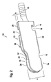
- the folded electrical contact element 10 represented in Figure 2 is produced by first bending the blank 11 transversely through substantially 180 degrees about the second bending region 28 and then about the first bending region 16.
- the convex nose 38 of the curved zone 37 of the bias portion 15 projects beyond the contour of the shoulders 24, 25 of the longitudinal edges 31 and 23 of the two guide portions 13 and 14.
- the region of the convex nose 38 of the bias portion 15 is resiliently elastically movable in the direction of the height (or width according to Figure 1) of the portions 13, 14, 15, because the bias portion 15 is relatively narrow and is joined over a relatively short second bending region 28 to the first guide portion 13.
- the spacing between the apex of the convex nose 38 and the longitudinal edges 21, 22 having the latching recess 17 or the first bending region 16 of the two guide portions 13 and 14 is thus resiliently elastically variable.
- the crimp projection 41 is formed into a longitudinally open sleeve.
- Both the holding tooth 36 on the first guide portion 13 and the recesses 18 and 29 serve to hold the electrical contact element 10 fixed in a plastic enclosure 45 ( Figures 3 and 4).
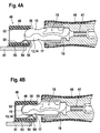
- Figures 3 and 4A, 4B show the detachable resiliently latching connection between the electrical contact element 10, which serves here as the plug portion in the plug-in connection 48, and a mating contact element 50, which is fixed for example on a printed circuit board 51 arranged in an enclosure 46.
- This electrical mating contact element 50 has a longitudinally extended contact element 53 enclosing the edge of the printed circuit board 51, which contact element has a latching nose 54 at its end which is the front end in the plug-in direction.
- a plane mating surface 52 is provided spaced from the contact element by an inside region of the enclosure 46.
- the electrical mating contact element 50 may comprise both the contact element 53 and the mating surface 52 in the form of a one-piece U-shaped bridge-like board.
- the thickness of the electrical mating contact element 50 corresponds to the width b ( Figure 2) of the electrical contact element 10.
- the clear width w at the mouth 55 of the electrical mating contact element 50 between the plane contact surface or mating surface 52 and the apex of the latching nose 54 on the contact element 53 is smaller than the measurement a between the apex of the convex nose 38 of the bias portion 15 and the underside (the longitudinal edges 21, 22 or the bending region 16) of the two guide portions 13 and 14 according to Figure 2.
- the latching nose 54 serves to engage in the latching recess 17 of the first bending region 16 between the two guide portions 13 and 14.
- the elastically resilient detachable latching connection between the contact element 10 and the socket-like mating contact element 50 is effected according to Figures 4A and 4B in such a way that plugging-in causes a relative movement between the bias portion 15 and the two guide portions 13 and 14 because of the differences in dimensions between the measurements a and w.
- the latching recess 17 of the contact element 10 settles over the latching nose 54 of the mating or socket contact element 50, and due to the elastic bias, the two guide portions 13 and 14 move towards the contact surface 53, while the convex nose 38 of the bias portion 15 continues to bear on the plane mating surface or contact surface 52 of the socket-contact element 50. Withdrawal is effected by reversing these steps.
- the socket-contact element 50 is soldered permanently to the printed circuit board 51 and/or held fast positively by means of pins engaging in printed-circuit-board bore holes.
- the contact surface 53 with the latching nose 54 may also comprise a bent spring contact band.
- contact element 10 and socket-like contact element 50 may be provided inverted in relation to Figure 3 or laterally, that is to say in a horizontal disposition. Furthermore, it is possible to provide the folded construction of the contact element 10 for the socket portion, and the construction of the contact element 50 for the plug portion.
- plug-in connector described above with the electrical contact element according to the invention as a plug portion or as a socket portion is suitable for example for battery charger connectors for mobile telephones. It is to be understood that other applications are also possible within the scope of invention.
Landscapes
- Coupling Device And Connection With Printed Circuit (AREA)
- Details Of Connecting Devices For Male And Female Coupling (AREA)
Abstract
Description
- Figure 1
- is a diagrammatic plan view of a punched blank for the production of an electrical contact element according to a preferred embodiment given by way of example of the present invention,
- Figure 2
- is a diagrammatic perspective representation of an electrical contact element according to the preferred embodiment, produced from the punched blank according to Figure 1,
- Figure 3
- is a dismantled longitudinally sectioned representation of a plug-in connector, plugged together with the electrical contact element according to Figure 2, and
- Figures 4A and 4B
- are representations corresponding to Figure 3, but in two states formed during the plugging operation.
Claims (18)
- An electrical contact element (10) comprising the plug portion of a plug-in connector (48) on mobile telephones for example, with which contact element a latching device is associated for detachable latching connection to a socket portion (50) of the plug-in connector (48), characterised in that the contact element (10) is punched and folded out of a plane, thin metal sheet (12) so as to provide a bias portion (15) that extends in parallel with at least one guide portion (13, 14) and is resiliently elastically movable perpendicular to the guide portion, and in that the latching device has a recess (17) in the region of a longitudinal edge (21, 22) of the guide portion (13, 14) and a nose (38) of the bias portion (15) opposite the recess (17) which projects beyond the guide portion (13, 14).
- A contact element according to Claim 1, characterised in that the folding between guide portion (13, 14) and bias portion (15) is effected about a longitudinal edge (31) which is opposite to the recess (17) of the guide portion (13, 14).
- A contact element according to Claim 1 or Claim 2, characterised in that a second guide portion (14, 13) is provided and in that the bias portion (15) is disposed between the two folded parallel guide portions (13, 14).
- A contact element according to Claim 3, characterised in that the two guide portions (13, 14) are joined and folded about their longitudinal edges (21, 22) that include the recess (17).
- A contact element according to Claim 4, characterised in that the recess (17) is disposed in a folding region or bending region (16) of the two guide portions (13, 14).
- A contact element according to any of the preceding claims, characterised in that the longitudinal edge of the bias portion (15) opposite to the folding region or bending region (28) of guide portion (13) and bias portion (15) ends before the longitudinal edge of the guide portion (13, 14).
- A contact element according to any of Claims 2 to 6, characterised in that the two guide portions (13, 14) are of approximately the same width.
- A contact element according to any of Claims 2 to 7, characterised in that the longitudinal edges of the two guide portions (13, 14) are provided in the region of the nose (38) of the bias portion (15) with an identical shoulder (24, 25) extending up to the front unattached end.
- A contact element according to any of the preceding claims, characterised in that the nose (38) of the bias portion (15) is defined by a convex arching of the longitudinal edge (32).
- A contact element according to any of the preceding claims, characterised in that the folding region or bending region (28) between the bias portion (15) and guide portion (13) is provided at an end region opposite to the nose (38).
- A contact element according to Claim 10, characterised in that the bias portion (15) is provided towards the rear with an undercut (29) in its longitudinal edge (32).
- A contact element according to at least one of the preceding claims, characterised in that an undercut is provided on one or both longitudinal edges (21, 22) of the guide portion or portions (13, 14) and on the longitudinal edge of the bias portion (15) facing the folding region (28).
- A contact element according any of the preceding laims, characterised in that the guide portion (13) joined to the bias portion (15) is provided with a protruding tooth (36).
- A contact element according to any of the preceding claims, characterised in that a crimp projection (41) is provided in one piece on a rear face (33) of one of the guide portions (14, 13), preferably the second guide portion (14).
- A plug-in connector having one or more contact elements (50) as a receiving portion and having one or more contact elements (10) according to at least one of the preceding claims as a plug portion, characterised in that the contact element (50) is constructed rigidly and has a contact surface (53) provided with a latching nose (54), in that a plane mating surface (52) is provided in the receiving portion spaced from and extending substantially parallel to the contact surface, and in that the clear width of the contact element (10) of the plug portion between the contact nose (38) of the bias portion (15) and the opposite longitudinal edge (21, 22) of the guide portion or portions (13, 14) is greater than the spacing between the plane mating surface (52) and the latching nose (54) of the contact surface (53).
- A plug-in connector according to Claim 15, characterised in that the plane mating surface (52) of the contact element (50) of the receiving portion has a width corresponding to the overall width of all contact elements (10) of the plug portion.
- A plug-in connector according to either one of Claims 16 or 17, characterised in that the latching nose (54) and the associated contact surface (53) of the receiving portion has a width corresponding to the width of the contact element (10) of the plug portion.
- A plug-in connector according to Claim 15 and/or 17, characterised in that the contact element (50) of the receiving portion is in one piece, preferably in the form of a U.
Applications Claiming Priority (2)
| Application Number | Priority Date | Filing Date | Title |
|---|---|---|---|
| DE10164386 | 2001-12-28 | ||
| DE10164386A DE10164386C1 (en) | 2001-12-28 | 2001-12-28 | Electrical pin contact element for plug-in connection has directly incorporated ratchet device securing pin contact element in cooperating socket part |
Publications (2)
| Publication Number | Publication Date |
|---|---|
| EP1326307A2 true EP1326307A2 (en) | 2003-07-09 |
| EP1326307A3 EP1326307A3 (en) | 2004-02-04 |
Family
ID=7711091
Family Applications (1)
| Application Number | Title | Priority Date | Filing Date |
|---|---|---|---|
| EP02027004A Withdrawn EP1326307A3 (en) | 2001-12-28 | 2002-12-03 | An electrical contact element for plug-in connectors |
Country Status (4)
| Country | Link |
|---|---|
| US (1) | US6629864B2 (en) |
| EP (1) | EP1326307A3 (en) |
| JP (1) | JP4199547B2 (en) |
| DE (1) | DE10164386C1 (en) |
Cited By (5)
| Publication number | Priority date | Publication date | Assignee | Title |
|---|---|---|---|---|
| EP1528629A3 (en) * | 2003-10-30 | 2006-02-01 | J.S.T. Mfg. Co., Ltd. | Contact and connector utilizing the same |
| US9142911B1 (en) | 2014-03-05 | 2015-09-22 | Standard Cable USA, Inc. | Insulating electrical plugs and method of manufacture |
| US9627793B2 (en) | 2014-03-05 | 2017-04-18 | Standard Cable USA, Inc. | Insulating electrical plugs and method of manufacture |
| US9744703B2 (en) | 2014-03-05 | 2017-08-29 | Standard Cable USA, Inc. | Method of manufacture insulating electrical plugs |
| CN112310736A (en) * | 2019-07-31 | 2021-02-02 | 住友电装株式会社 | Terminal and connector for substrate |
Families Citing this family (6)
| Publication number | Priority date | Publication date | Assignee | Title |
|---|---|---|---|---|
| EP1288322A1 (en) | 2001-08-29 | 2003-03-05 | Sidmar N.V. | An ultra high strength steel composition, the process of production of an ultra high strength steel product and the product obtained |
| DE10351289B4 (en) * | 2003-08-13 | 2008-01-10 | Phoenix Contact Gmbh & Co. Kg | Jumper for electrical connection and / or connection terminals |
| JP4299184B2 (en) * | 2004-04-23 | 2009-07-22 | 矢崎総業株式会社 | Board connection board terminal |
| CN103474803B (en) * | 2012-06-06 | 2016-06-22 | 宁波思宏电器工业有限公司 | A kind of plug slice and manufacture method thereof |
| JP6125895B2 (en) * | 2013-05-13 | 2017-05-10 | 矢崎総業株式会社 | Female terminal fitting |
| JP6651427B2 (en) * | 2016-09-08 | 2020-02-19 | ヒロセ電機株式会社 | Electrical connector and electrical connector assembly |
Family Cites Families (10)
| Publication number | Priority date | Publication date | Assignee | Title |
|---|---|---|---|---|
| AT362005B (en) * | 1976-08-18 | 1981-04-27 | Wago Kontakttechnik Gmbh | ELECTRICAL CONNECTING OR CONNECTING DEVICE |
| FR2624311B1 (en) * | 1987-12-07 | 1990-05-04 | Bonhomme F R | IMPROVEMENTS IN ELASTICALLY DEFORMABLE ELECTRIC CONTACT MEMBERS, TO BE INCORPORATED IN CONNECTORS, AND IN THEIR MANUFACTURING METHODS |
| DE3927682C3 (en) * | 1988-08-23 | 2000-04-20 | Yazaki Corp | Connector receptacle and method for its manufacture |
| FR2649251B1 (en) * | 1989-07-03 | 1992-09-04 | Labinal | FEMALE ELECTRIC CONTACT MEMBER |
| US5004438A (en) * | 1990-07-03 | 1991-04-02 | Precision Interconnect Corporation | Flexible pin type contact |
| FR2712739B1 (en) * | 1993-11-18 | 1995-12-15 | Cinch Connecteurs Sa | Female electrical contact member. |
| DE9319110U1 (en) * | 1993-12-13 | 1995-04-13 | WECO Wester, Ebbinghaus & Co, 63452 Hanau | Single or multi-pole test plug for high-performance terminals |
| DE4411306C1 (en) * | 1994-03-31 | 1995-05-11 | Phoenix Contact Gmbh & Co | Electrical connecting terminal, in particular a modular terminal, having a plug link, as well as such a plug link |
| FR2726130A1 (en) * | 1994-10-20 | 1996-04-26 | Amp France | ELECTRIC TERMINAL WITH FLAT PLATE AND ASSEMBLY OF ELECTRICAL CONNECTORS |
| FR2810458B1 (en) * | 2000-06-16 | 2004-04-09 | Entrelec Sa | ELECTRIC INTERCONNECTION COMB |
-
2001
- 2001-12-28 DE DE10164386A patent/DE10164386C1/en not_active Expired - Fee Related
-
2002
- 2002-12-03 EP EP02027004A patent/EP1326307A3/en not_active Withdrawn
- 2002-12-20 US US10/325,139 patent/US6629864B2/en not_active Expired - Fee Related
-
2003
- 2003-01-06 JP JP2003000009A patent/JP4199547B2/en not_active Expired - Fee Related
Cited By (6)
| Publication number | Priority date | Publication date | Assignee | Title |
|---|---|---|---|---|
| EP1528629A3 (en) * | 2003-10-30 | 2006-02-01 | J.S.T. Mfg. Co., Ltd. | Contact and connector utilizing the same |
| US9142911B1 (en) | 2014-03-05 | 2015-09-22 | Standard Cable USA, Inc. | Insulating electrical plugs and method of manufacture |
| US9627793B2 (en) | 2014-03-05 | 2017-04-18 | Standard Cable USA, Inc. | Insulating electrical plugs and method of manufacture |
| US9744703B2 (en) | 2014-03-05 | 2017-08-29 | Standard Cable USA, Inc. | Method of manufacture insulating electrical plugs |
| CN112310736A (en) * | 2019-07-31 | 2021-02-02 | 住友电装株式会社 | Terminal and connector for substrate |
| CN112310736B (en) * | 2019-07-31 | 2023-01-31 | 住友电装株式会社 | Terminal and connector for substrate |
Also Published As
| Publication number | Publication date |
|---|---|
| DE10164386C1 (en) | 2003-04-24 |
| JP4199547B2 (en) | 2008-12-17 |
| US6629864B2 (en) | 2003-10-07 |
| US20030124918A1 (en) | 2003-07-03 |
| EP1326307A3 (en) | 2004-02-04 |
| JP2003234153A (en) | 2003-08-22 |
Similar Documents
| Publication | Publication Date | Title |
|---|---|---|
| US8092232B2 (en) | Board-to-board connector | |
| KR101639801B1 (en) | Connector | |
| CN104659512B (en) | Pin contact for an electrical connector | |
| US9711897B2 (en) | UVA battery connector | |
| US6224432B1 (en) | Electrical contact with orthogonal contact arms and offset contact areas | |
| US8465298B2 (en) | Board-to-board connector | |
| US6244910B1 (en) | Electrical box contact with stress limitation | |
| KR20000076849A (en) | Electrical connector | |
| EP1120861A2 (en) | Electrical connector having an improved female contact | |
| CN105720401A (en) | Electrical connector | |
| KR20210113076A (en) | Electric connector for circuit board and electric connector with circuit board attached thereto | |
| CN110277659B (en) | Connecting piece and socket | |
| CN104253337A (en) | Connector, and header and socket included in the same | |
| CN104253345B (en) | Connector and plug and socket used in the connector | |
| KR101514372B1 (en) | Connector | |
| EP2613410A1 (en) | Structure for preventing improper insertion of connector | |
| EP0559057A1 (en) | Electrical connector terminal | |
| JP2007149394A (en) | connector | |
| JP4058770B2 (en) | Electrical connector | |
| JP2005183160A (en) | Female contact | |
| JP2005294217A (en) | Pressure contact type contact and electrical connector using the same | |
| JP4199547B2 (en) | Electrical contact elements for plug-in connectors | |
| CN108780956B (en) | Electrical contact element for supporting bus elements of a rail bus system | |
| EP3340389A1 (en) | Connector device | |
| JP3620833B2 (en) | Module connector |
Legal Events
| Date | Code | Title | Description |
|---|---|---|---|
| PUAI | Public reference made under article 153(3) epc to a published international application that has entered the european phase |
Free format text: ORIGINAL CODE: 0009012 |
|
| AK | Designated contracting states |
Designated state(s): AT BE BG CH CY CZ DE DK EE ES FI FR GB GR IE IT LI LU MC NL PT SE SI SK TR |
|
| AX | Request for extension of the european patent |
Extension state: AL LT LV MK RO |
|
| PUAL | Search report despatched |
Free format text: ORIGINAL CODE: 0009013 |
|
| AK | Designated contracting states |
Kind code of ref document: A3 Designated state(s): AT BE BG CH CY CZ DE DK EE ES FI FR GB GR IE IT LI LU MC NL PT SE SI SK TR |
|
| AX | Request for extension of the european patent |
Extension state: AL LT LV MK RO |
|
| AKX | Designation fees paid | ||
| REG | Reference to a national code |
Ref country code: DE Ref legal event code: 8566 |
|
| STAA | Information on the status of an ep patent application or granted ep patent |
Free format text: STATUS: THE APPLICATION IS DEEMED TO BE WITHDRAWN |
|
| 18D | Application deemed to be withdrawn |
Effective date: 20040805 |
|
| REG | Reference to a national code |
Ref country code: HK Ref legal event code: WD Ref document number: 1053749 Country of ref document: HK |