EP1326262A1 - Pole armature - Google Patents
Pole armature Download PDFInfo
- Publication number
- EP1326262A1 EP1326262A1 EP02090357A EP02090357A EP1326262A1 EP 1326262 A1 EP1326262 A1 EP 1326262A1 EP 02090357 A EP02090357 A EP 02090357A EP 02090357 A EP02090357 A EP 02090357A EP 1326262 A1 EP1326262 A1 EP 1326262A1
- Authority
- EP
- European Patent Office
- Prior art keywords
- pole
- cooling fins
- carrier
- cooling
- polar
- Prior art date
- Legal status (The legal status is an assumption and is not a legal conclusion. Google has not performed a legal analysis and makes no representation as to the accuracy of the status listed.)
- Withdrawn
Links
Images


Classifications
-
- H—ELECTRICITY
- H01—ELECTRIC ELEMENTS
- H01H—ELECTRIC SWITCHES; RELAYS; SELECTORS; EMERGENCY PROTECTIVE DEVICES
- H01H9/00—Details of switching devices, not covered by groups H01H1/00 - H01H7/00
- H01H9/52—Cooling of switch parts
-
- H—ELECTRICITY
- H01—ELECTRIC ELEMENTS
- H01H—ELECTRIC SWITCHES; RELAYS; SELECTORS; EMERGENCY PROTECTIVE DEVICES
- H01H33/00—High-tension or heavy-current switches with arc-extinguishing or arc-preventing means
- H01H33/60—Switches wherein the means for extinguishing or preventing the arc do not include separate means for obtaining or increasing flow of arc-extinguishing fluid
- H01H33/66—Vacuum switches
- H01H33/6606—Terminal arrangements
- H01H2033/6613—Cooling arrangements directly associated with the terminal arrangements
-
- H—ELECTRICITY
- H01—ELECTRIC ELEMENTS
- H01H—ELECTRIC SWITCHES; RELAYS; SELECTORS; EMERGENCY PROTECTIVE DEVICES
- H01H33/00—High-tension or heavy-current switches with arc-extinguishing or arc-preventing means
- H01H33/60—Switches wherein the means for extinguishing or preventing the arc do not include separate means for obtaining or increasing flow of arc-extinguishing fluid
- H01H33/66—Vacuum switches
- H01H33/666—Operating arrangements
- H01H2033/6665—Details concerning the mounting or supporting of the individual vacuum bottles
-
- H—ELECTRICITY
- H01—ELECTRIC ELEMENTS
- H01H—ELECTRIC SWITCHES; RELAYS; SELECTORS; EMERGENCY PROTECTIVE DEVICES
- H01H33/00—High-tension or heavy-current switches with arc-extinguishing or arc-preventing means
- H01H33/02—Details
- H01H33/025—Terminal arrangements
-
- H—ELECTRICITY
- H01—ELECTRIC ELEMENTS
- H01H—ELECTRIC SWITCHES; RELAYS; SELECTORS; EMERGENCY PROTECTIVE DEVICES
- H01H33/00—High-tension or heavy-current switches with arc-extinguishing or arc-preventing means
- H01H33/60—Switches wherein the means for extinguishing or preventing the arc do not include separate means for obtaining or increasing flow of arc-extinguishing fluid
- H01H33/66—Vacuum switches
- H01H33/6606—Terminal arrangements
-
- H—ELECTRICITY
- H01—ELECTRIC ELEMENTS
- H01H—ELECTRIC SWITCHES; RELAYS; SELECTORS; EMERGENCY PROTECTIVE DEVICES
- H01H33/00—High-tension or heavy-current switches with arc-extinguishing or arc-preventing means
- H01H33/60—Switches wherein the means for extinguishing or preventing the arc do not include separate means for obtaining or increasing flow of arc-extinguishing fluid
- H01H33/66—Vacuum switches
- H01H33/666—Operating arrangements
- H01H33/6661—Combination with other type of switch, e.g. for load break switches
Definitions
- the invention relates to a polar armature for mounting and contacting an interrupter unit of a circuit breaker in a gas atmosphere, in particular protective gas atmosphere, consisting of a pole head and a pole carrier, each have cooling fins provided for cooling.
- DE 39 41 388 A1 describes a vacuum switch Circuit breaker known to cool the vacuum switch has a boiling cooling device.
- the evaporative cooler is thermally conductive with a contact piece of the vacuum switch connected and comprises a boiling chamber with boiling liquid, a collecting channel, a closed end Guide tube and a heat sink. Because of the current flow When heat occurs, the evaporative coolant is evaporated and in the gaseous state in the closed guide tube where it condenses again due to the cooling effect of the heat sink and passed back to the contact piece in the liquid state becomes.
- Such a boiling cooling device is in their Construction complex and increases the manufacturing costs such vacuum switch considerably.
- a circuit breaker is disclosed under the designation 3AH3, which comprises polar fittings with cooling fins for cooling the contacts of the vacuum switch.
- the circuit breakers shown are intended for operation in a sulfur hexafluoride atmosphere.
- the known polar fittings have the disadvantage that their cooling capacity is insufficient.
- Different-phase poles of a circuit breaker can therefore only be installed at a relatively large distance from one another, as a result of which extensive switchgear panels are produced, particularly in medium-voltage switchgear.
- the invention has for its object the aforementioned Polar armature to improve that even with more compact Construction of the circuit breaker a sufficiently large Cooling is provided.
- the invention solves this problem in that the cooling fins a distance of 6 to 13 mm and in the flow direction of the Shielding gas have a length of 150 to 200 mm.
- the invention is based on the finding that for preservation a sufficiently high cooling capacity as large as possible Heat exchange surface between the polar armature and the cooling fluid must be provided. With a given installation space consequently, the distance between the cooling fins must be used for the polar fitting be reduced. This increases the number of Cooling fins and thus to those available for heat transfer standing area.
- the cooling capacity In addition to the size of the heat exchange surface is the cooling capacity but also depending on the speed, with a cooling fluid and in the present case the protective gas on the Flows past heat exchange surface. Will the distance between If the cooling fins are too low, there is a gradual flow-related Clogging of the flow channels, so that at the flow velocity at short intervals between the cooling fins and consequently the cooling can be reduced.
- the flow profile also depends on their length in the flow direction.
- a length range is therefore specified in addition to a distance range.
- the subject of claim 1 is therefore a compact polar armature with the largest possible heat exchange surface, whereby at the same time the risk of clogging of the cooling channels is avoided by unfavorable gas flow.
- invention Polar fittings therefore have a compared to the stand technology increased cooling effect.
- this improved Cooling effect does not necessarily mean an increase in the external dimensions the polar armatures, but the Success according to the invention also on improved utilization of a given installation space, for example, can by simply replacing known polar fittings by polar fittings according to the invention in already installed Plants with higher currents can be switched.
- the invention further solves the problem in that the Pole head and / or pole carrier have / has outer boundary walls, with cooling fins between the boundary walls and thus inside the pole head and / or pole carrier run. In this way, those are inside Cooling fins are stacked, the Connect boundary walls with each other and thus mechanically stabilize. The shielding gas entry between the cooling fins or the shielding gas outlet from these takes place at this Further development mainly on the sides of the pole head instead, not from the massive boundary walls are shielded.
- the invention also achieves the object in that the pole head and / or pole carriers along their envelope, cubic are / is designed and thus form flat side walls, between which the cooling fins extend. Through the Side walls on the one hand and two opposite Cooling fins on the other hand are thus opened on both sides Cooling channels defined through which the surrounding Gas flows through due to convection.
- Polar armature advantageously made of metal and in particular Copper, aluminum or alloys of these two metals.
- the polar armature according to the invention is for operation in a gas atmosphere intended.
- the gas atmosphere is advantageous however, a protective gas atmosphere, being the protective gas Sulfur hexafluoride is preferably used.
- the polar armature according to the invention expediently has or but also only the pole head or only the pole carrier two line connections on, the opposite one another Boundary walls are arranged. That way the current flowing through the respective component in two partial flows split so that the heating of the pole head and / or pole carrier as a result of his or her internal resistance is reduced.
- the pole head and / or pole carrier advantageously has in addition, or instead, split branches of the flowing over the pole head and / or pole carrier Current into several partial flows.
- the splitting into partial streams causes a reduction in current-induced heating of the respective component due to its internal resistance.
- the respective component can be parallel to the boundary walls have a central wall, between the boundary walls in the middle of each Component is arranged and there the cooling fins connects with each other.
- the connection points between the The middle wall and the cooling fins then provide power branches represents that for splitting the total current into parallel Partial streams are suitable.
- the pole carrier has a carrier core that massive opposite side walls and one connecting wall arranged between the side walls for Carrying a busbar connection includes. Between Side walls and the connecting wall opposite cooling fins are provided to prevent the entry of the protective gas allow inside the carrier core. Through the next to the Connection wall additional connection of the side walls of the carrier core via cooling fins becomes the heat exchange surface further enlarged. At the same time there are openings between the cooling fins for the inert gas entry and thus provided for internal cooling of the carrier core.
- the pole carrier has a support core that is cubic or cuboid is designed and massive opposite side walls as well as connecting the side walls Has cooling fins, one inside the support core Recess provided for moving parts of the interrupter unit are.
- the cooling essentially inside the pole carrier.
- the envelope of the outer cooling fins is advantageously in the Area of the busbar connections or the connection wall, at which the busbar connection is usually provided is formed uniformly. Put another way the envelope of the cooling fins in one to the connecting wall parallel plane. With three-pole vacuum switches, too the busbars of the other-phase power connections in the Passed near the connecting wall. Because of the uniform Course of the envelope in the immediate vicinity other-phase busbars become an electrical discharge avoided between these components and the dielectric Dielectric strength of circuit breakers with the invention Polar fittings are equipped, improved.
- the polar armature according to the invention is advantageously made of Made of aluminum, which creates a surface treatment Improvement of heat exchange due to heat radiation is superfluous.
- aluminum is cheaper compared to the copper that can of course also be used, see above that with this further development of the invention also the manufacturing costs for the polar fittings are reduced.
- FIG. 1 shows a switch pole of a circuit breaker 1 with an embodiment of the polar armature according to the invention, which consists of a pole head 2 and a pole carrier 3.
- An interrupter unit is located between the pole head 2 and the pole carrier 3 4 arranged in the embodiment shown is a vacuum switch.
- For mechanical connection and holder of the polar armature is made of a non-conductive Insulated Polschale 5 provided that itself extends to both sides of the vacuum switch 4 and to this established connection points with the pole head 2 and with the pole carrier 3 is connected.
- the pole carrier 3 has a recess 6, which the implementation of shift linkage or other components of a drive unit to the vacuum switch 4 allows the moving contact bring the vacuum switch 4 into contact position or the current flow in a contact-free position interrupt.
- busbar connections 7 on the pole carrier 3 with holes 8 recognizable, each for connecting a not shown current-carrying busbar of a medium-voltage switchgear are provided.
- By on both Side of the pole carrier 3 comes distributed supply of the current it to an improved distribution of the pole carrier 3rd flowing currents and thus to less heating in Result of the ohmic resistance of the pole carrier 3.
- the recess 6 is on their top and bottom are delimited by cooling fins 9, which are stacked one behind the other and form channels open on both sides, which prevent the entrance of the Enable protective gas.
- the pole head 2 like the pole carrier 3, is cubic and has two lateral boundary walls 10, the arranged opposite each other and through the cooling fins 9 are connected to each other. Are in a central area the cooling fins 9 through a web or a central wall 11 connected with each other.
- connection connections 12 on the boundary walls 10 provided in the form of threaded holes.
- the number and arrangement the connector 12 provides a variety different connection options ready in order to different geometric specifications of the user the most variable possible connection of an electrical To enable the leader.
- connection connections 12 are not at the in Figure 1 recognizable other boundary wall 10 are provided, the current can be discharged through two conductors, so that it to a distribution of the flowing over the vacuum switch 4 Electricity comes in two substreams.
- the current splitting will by the arrangement of the cooling fins 9 inside the pole head 2 increased even further, because in this way a multitude of branching points between the vacuum switch 4 contacting receiving wall 13 and the connection connections 12 to be attached conductors are provided.
- the distance between the cooling fins 9 is in the preferred shown Embodiment 10 mm.
- the pole head 2 and the pole carrier 3 to a height of 200 or 240 mm, so that the length of the cooling fins facing each other 9 trained channels is also 20 or 24 mm.
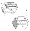
- Figure 2 shows a perspective view of the isolated Polar armature according to Fig. 1.
- the pole carrier 3 has an inner support core has, which consists of two opposite side walls 14 and cooling fins 9, which are the side walls 14 connect with each other, so that inside the support core the recess 6 is defined.
- the recess is 6 designed open on both sides.
- a holding wall 15 facing the pole carrier 2 can be seen, in the one receptacle 16 for positively holding the vacuum switch 4 is provided.
- the retaining wall 15 is made possible at a distance arranged to the support core open on both sides. By the distance between retaining wall 15 and the support core is above in addition, the gas circulation improved.
- the envelope the support core and the retaining wall is cubic.
- outer cooling fins are attached to the side walls 14.
- the pole head 2 is shown in FIG. 2 from the front. In this view are next to the receiving wall 13 for holding the vacuum switch 4 both stacked inside Cooling fins 9 as well as the connection connections 12 recognizable. It is also made clear that the boundary walls 10 not consistently solid according to the invention must be 17 contours in the lower front area the cooling fins 9 can be seen.
- Figure 3 shows a further embodiment of the invention Pole carrier, in which the support core of the pole carrier 3 also consists of two solid side walls 14, but not exclusively by cooling fins 9, but above through a likewise massive connecting wall 18 are connected.
- the connection wall 18 is for connection provided a single busbar connection.
- the recess 6 is located opposite the connecting wall 18 however, limited by cooling fins 9.
- cooling fins 9 are provided, the envelope in Area of the busbar connection 18 a parallel to the vacuum switch 4 extending plane.
- the side walls 14 are continuous up to the holding wall 15 formed so that the stability of the pole carrier 3 against the embodiment shown in Figure 2 is increased.
Landscapes
- Arc-Extinguishing Devices That Are Switches (AREA)
- Breakers (AREA)
Abstract
Description
Die Erfindung betrifft eine Polarmatur zur Halterung und Kontaktierung einer Unterbrechereinheit eines Leistungsschalters in einer Gasatmosphäre, insbesondere Schutzgasatmosphäre, bestehend aus einem Polkopf und einem Polträger, die jeweils zur Kühlung vorgesehene Kühlrippen aufweisen.The invention relates to a polar armature for mounting and contacting an interrupter unit of a circuit breaker in a gas atmosphere, in particular protective gas atmosphere, consisting of a pole head and a pole carrier, each have cooling fins provided for cooling.
Es ist ganz allgemein bekannt, dass sich Kontaktstücke bei Stromdurchfluss erwärmen. Insbesondere in der Mittelspannungstechnik kann die infolge hoher Ströme eintretende Erwärmung einer Unterbrechereinheit die Einsetzbarkeit eines Leistungsschalters begrenzen. So gilt es beispielsweise vorgegebene Höchsttemperaturen nicht zu überschreiten, ab denen esbeispielsweise durch Schmelzen oder Oxidieren anderer Bauteile - zu irreparablen Schäden in der Anlage kommt, in die der Leistungsschalter integriert ist. Aus diesem Grunde ist es zweckmäßig, Kühlelemente vorzusehen, mit deren Hilfe ein Herabsetzen der Temperatur bzw. ein Betreiben des Leistungsschalters bei höheren Strömen ermöglicht ist. Solche Kühlelemente sind insbesondere bei Vakuumschaltern vorteilhaft, da die Kontaktstücke solcher Leistungsschalter im Vakuum angeordnet sind und somit nicht durch konvektive Gasströmung gekühlt werden können.It is very common knowledge that contact pieces at Warm up current flow. Especially in medium voltage technology can the warming that occurs as a result of high currents an interrupter unit the applicability of a circuit breaker limit. For example, there are predefined ones Do not exceed maximum temperatures, for example by melting or oxidizing other components - irreparable damage to the system occurs, in which the circuit breaker is integrated. This is why it is appropriate to provide cooling elements with the help of which Lowering the temperature or operating the circuit breaker is possible at higher currents. Such cooling elements are particularly advantageous for vacuum switches because the contact pieces of such circuit breakers arranged in a vacuum are and therefore not cooled by convective gas flow can be.
Aus der DE 39 41 388 A1 ist ein als Vakuumschalter ausgebildeter Leistungsschalter bekannt, der zum Kühlen des Vakuumschalters eine Siedekühlvorrichtung aufweist. Die Siedekühlvorrichtung ist wärmeleitend mit einem Kontaktstück des Vakuumschalters verbunden und umfasst eine Siedekammer mit Siedekühlflüssigkeit, einen Sammelkanal, ein endseitig geschlossenes Leitrohr sowie einen Kühlkörper. Durch die bei Stromfluss auftretende Wärme wird das Siedekühlmittel verdampft und im gasförmigen Zustand in das geschlossene Leitrohr geführt, wo es aufgrund der Kühlwirkung des Kühlkörpers wieder kondensiert und im flüssigen Zustand zurück zum Kontaktstück geleitet wird. Eine solche Siedekühlvorrichtung ist jedoch in ihrer Konstruktion aufwendig und erhöht die Herstellungskosten solcher Vakuumschalter beträchtlich.DE 39 41 388 A1 describes a vacuum switch Circuit breaker known to cool the vacuum switch has a boiling cooling device. The evaporative cooler is thermally conductive with a contact piece of the vacuum switch connected and comprises a boiling chamber with boiling liquid, a collecting channel, a closed end Guide tube and a heat sink. Because of the current flow When heat occurs, the evaporative coolant is evaporated and in the gaseous state in the closed guide tube where it condenses again due to the cooling effect of the heat sink and passed back to the contact piece in the liquid state becomes. Such a boiling cooling device is in their Construction complex and increases the manufacturing costs such vacuum switch considerably.
Aus einem Katalog der Siemens AG mit der Bestellnummer
E50001-U229-A110 sowie aus der Veröffentlichung im Internet
unter Adresse
http://www.e.ptd.siemens.com/webapp-/EVWebApp/index de.jsp ist
die eingangs genannte gattungsgemäße Polarmatur bereits bekannt.
In dem Katalog ist unter der Bezeichnung 3AH3 ein
Leistungsschalter offenbart, der zur Kühlung der Kontakte des
Vakuumschalters Polarmaturen mit Kühlrippen umfasst. Die gezeigten
Leistungsschalter sind zum Betrieb in einer Schwefelhexafluorid-Atmosphäre
vorgesehen. Den vorbekannten Polarmaturen
haftet jedoch der Nachteil an, dass ihre Kühlleistung
nicht ausreichend ist. Verschiedenphasige Pole eines Leistungsschalters
können daher nur mit einem relativ großen Abstand
voneinander montiert werden, wodurch raumgreifende
Schaltfelder insbesondere in Mittelspannungsschaltanlagen erzeugt
werden.From a catalog of Siemens AG with the order number E50001-U229-A110 and from the publication on the Internet at address
http://www.e.ptd.siemens.com/webapp-/EVWebApp/index de.jsp the generic polar armature mentioned above is already known. In the catalog, a circuit breaker is disclosed under the designation 3AH3, which comprises polar fittings with cooling fins for cooling the contacts of the vacuum switch. The circuit breakers shown are intended for operation in a sulfur hexafluoride atmosphere. However, the known polar fittings have the disadvantage that their cooling capacity is insufficient. Different-phase poles of a circuit breaker can therefore only be installed at a relatively large distance from one another, as a result of which extensive switchgear panels are produced, particularly in medium-voltage switchgear.
Der Erfindung liegt die Aufgabe zugrunde, die eingangs genannte Polarmatur dahin zu verbessern, dass auch bei kompakter Bauweise des Leistungsschalters eine ausreichend große Kühlung bereitgestellt wird. The invention has for its object the aforementioned Polar armature to improve that even with more compact Construction of the circuit breaker a sufficiently large Cooling is provided.
Die Erfindung löst diese Aufgabe dadurch, dass die Kühlrippen einen Abstand von 6 bis 13 mm und in Strömungsrichtung des Schutzgases eine Länge von 150 bis 200 mm aufweisen.The invention solves this problem in that the cooling fins a distance of 6 to 13 mm and in the flow direction of the Shielding gas have a length of 150 to 200 mm.
Der Erfindung liegt die Erkenntnis zugrunde, dass zum Erhalt einer ausreichend hohen Kühlleistung eine möglichst große Wärmeaustauschfläche zwischen der Polarmatur und dem Kühlungsfluid bereitgestellt werden muss. Bei vorgegebenem Bauraum für die Polarmatur muss folglich der Abstand der Kühlrippen verringert werden. Dadurch erhöht sich die Anzahl der Kühlrippen und somit an die für die Wärmeübertragung zur Verfügung stehende Fläche.The invention is based on the finding that for preservation a sufficiently high cooling capacity as large as possible Heat exchange surface between the polar armature and the cooling fluid must be provided. With a given installation space consequently, the distance between the cooling fins must be used for the polar fitting be reduced. This increases the number of Cooling fins and thus to those available for heat transfer standing area.
Neben der Größe der Wärmeaustauschfläche ist die Kühlleistung jedoch darüber hinaus auch von der Geschwindigkeit abhängig, mit der ein Kühlungsfluid und vorliegend das Schutzgas an der Wärmeaustauschfläche vorbeiströmt. Wird der Abstand zwischen den Kühlrippen zu gering, kommt es zur allmählichen strömungsbedingten Verstopfung der Strömungskanäle, so dass bei zu geringen Abständen der Kühlrippen die Strömungsgeschwindigkeit und folglich auch die Kühlung reduziert werden.In addition to the size of the heat exchange surface is the cooling capacity but also depending on the speed, with a cooling fluid and in the present case the protective gas on the Flows past heat exchange surface. Will the distance between If the cooling fins are too low, there is a gradual flow-related Clogging of the flow channels, so that at the flow velocity at short intervals between the cooling fins and consequently the cooling can be reduced.
Der Strömungsverlauf ist neben dem Abstand zwischen den Kühlrippen
auch von deren Länge in Strömungsrichtung abhängig. In
Anspruch 1 ist daher neben einem Abstandsbereich auch ein
Längenbereich angegeben. Anhaltspunkte zur Festlegung des
Mindestabstandes der jeweiligen Kühlrippen ergeben sich aus
der allgemein bekannten thermodynamisch hergeleiteten Gleichung
zur Berechnung der Grenzschichtdichte δ in Abhängigkeit
der Länge x der Kühlrippen
Gegenstand des Anspruchs 1 ist daher eine kompakte Polarmatur mit einer möglichst großen Wärmeaustauschfläche, wobei gleichzeitig die Gefahr einer Verstopfung von Kühlungskanälen durch unvorteilhafte Gasströmung vermieden ist. Erfindungsgemäße Polarmaturen weisen daher eine im Vergleich zum Stand der Technik erhöhte Kühlwirkung auf. Da diese verbesserte Kühlwirkung nicht zwangsläufig auf eine Vergrößerung der Außenmaße der Polarmaturen zurückzuführen ist, sondern sich der erfindungsgemäße Erfolg auch auf eine verbesserte Ausnutzung eines beispielsweise vorgegebenen Bauraums zurückführen läßt, können über den einfachen Austausch vorbekannter Polarmaturen durch erfindungsgemäße Polarmaturen in bereits installierten Anlagen höhere Ströme geschaltet werden.The subject of claim 1 is therefore a compact polar armature with the largest possible heat exchange surface, whereby at the same time the risk of clogging of the cooling channels is avoided by unfavorable gas flow. invention Polar fittings therefore have a compared to the stand technology increased cooling effect. As this improved Cooling effect does not necessarily mean an increase in the external dimensions the polar armatures, but the Success according to the invention also on improved utilization of a given installation space, for example, can by simply replacing known polar fittings by polar fittings according to the invention in already installed Plants with higher currents can be switched.
Die Erfindung löst die Aufgabe weiterhin dadurch, dass der Polkopf und/oder Polträger äußere Begrenzungswandungen aufweisen/aufweist, wobei Kühlrippen zwischen den Begrenzungswandungen und somit im Inneren des Polkopfes und/oder Polträgers verlaufen. Auf diese Weise sind die im Inneren verlaufenden Kühlrippen stapelweise angeordnet, wobei sie die Begrenzungswandungen miteinander verbinden und somit mechanisch stabilisieren. Der Schutzgaseintritt zwischen die Kühlrippen bzw. der Schutzgasaustritt aus diesen findet bei dieser Weiterentwicklung im Wesentlichen an den Seiten des Polkopfes statt, die nicht von den massiven Begrenzungswandungen abgeschirmt sind.The invention further solves the problem in that the Pole head and / or pole carrier have / has outer boundary walls, with cooling fins between the boundary walls and thus inside the pole head and / or pole carrier run. In this way, those are inside Cooling fins are stacked, the Connect boundary walls with each other and thus mechanically stabilize. The shielding gas entry between the cooling fins or the shielding gas outlet from these takes place at this Further development mainly on the sides of the pole head instead, not from the massive boundary walls are shielded.
Die Erfindung löst die Aufgabe ferner dadurch, dass Polkopf und/oder Polträger längs ihrer/seiner Einhüllenden kubisch ausgebildet sind/ist und somit plane Seitenwandungen ausbilden, zwischen denen sich die Kühlrippen erstrecken. Durch die Seitenwandungen einerseits und zwei sich gegenüberliegenden Kühlrippen andererseits werden somit flächige beidseitig ge-öffnete Kühlungskanäle definiert, durch die das sie umgebende Gas aufgrund von Konvektion hindurchströmt.The invention also achieves the object in that the pole head and / or pole carriers along their envelope, cubic are / is designed and thus form flat side walls, between which the cooling fins extend. Through the Side walls on the one hand and two opposite Cooling fins on the other hand are thus opened on both sides Cooling channels defined through which the surrounding Gas flows through due to convection.
Im Rahmen der Erfindung ist es selbstverständlich auch möglich die zuvor beschriebenen Lösungen der Aufgabe miteinander beliebig zu kombinieren.It is of course also possible within the scope of the invention the previously described solutions to the problem with each other to combine as desired.
Im Hinblick auf eine gute Wärmeleitfähigkeit besteht die Polarmatur vorteilhafterweise aus Metall und insbesondere aus Kupfer, Aluminium oder aus Legierungen dieser beiden Metalle.With regard to good thermal conductivity, there is Polar armature advantageously made of metal and in particular Copper, aluminum or alloys of these two metals.
Die erfindungsgemäße Polarmatur ist zum Betrieb in einer Gasatmosphäre vorgesehen. Vorteilhafterweise ist die Gasatmosphäre jedoch eine Schutzgasatmosphäre, wobei als Schutzgas Schwefelhexafluorid bevorzugt eingesetzt wird.The polar armature according to the invention is for operation in a gas atmosphere intended. The gas atmosphere is advantageous however, a protective gas atmosphere, being the protective gas Sulfur hexafluoride is preferably used.
Zweckmäßigerweise weist die erfindungsgemäße Polarmatur oder aber auch nur der Polkopf oder nur der Polträger zwei Leitungsanschlüsse auf, die aneinander gegenüberliegenden Begrenzungswandungen angeordnet sind. Auf diese Weise wird der über das jeweilige Bauteil fließende Strom in zwei Teilströme aufgeteilt, so dass die Erwärmung des Polkopfes und/oder Polträgers als Folge seines oder ihres Innenwiderstandes verringert wird.The polar armature according to the invention expediently has or but also only the pole head or only the pole carrier two line connections on, the opposite one another Boundary walls are arranged. That way the current flowing through the respective component in two partial flows split so that the heating of the pole head and / or pole carrier as a result of his or her internal resistance is reduced.
Vorteilhafterweise weist der Polkopf und/oder Polträger darüber hinaus oder stattdessen Stromverzweigungen zum Aufteilen des über den Polkopf und/oder Polträger fließenden Stromes in mehrere Teilströme auf. Die Aufspaltung in Teilströme bewirkt ein Herabsetzen der strominduzierten Erwärmung des jeweiligen Bauteils in Folge seines Innenwiderstandes. Zur Ausbildung solcher Verzweigungen, die auch an Verbindungsstellen zwischen Kühlrippen und den Begrenzungswandungen gebildet werden, kann das jeweilige Bauteil eine parallel zu den Begrenzungswandungen verlaufende Mittenwandung aufweisen, die zwischen den Begrenzungswandungen in der Mitte des jeweiligen Bauteils angeordnet ist und dort die Kühlungsrippen miteinander verbindet. Die Verbindungsstellen zwischen der Mittenwandung und den Kühlrippen stellen dann Stromverzweigungen dar, die zum Aufspalten des Gesamtstromes in parallele Teilströme geeignet sind.The pole head and / or pole carrier advantageously has in addition, or instead, split branches of the flowing over the pole head and / or pole carrier Current into several partial flows. The splitting into partial streams causes a reduction in current-induced heating of the respective component due to its internal resistance. To form such branches, which are also at junctions between cooling fins and the boundary walls are formed, the respective component can be parallel to the boundary walls have a central wall, between the boundary walls in the middle of each Component is arranged and there the cooling fins connects with each other. The connection points between the The middle wall and the cooling fins then provide power branches represents that for splitting the total current into parallel Partial streams are suitable.
Bei einer zweckmäßigen Weiterentwicklung der erfindungsgemäßen Polarmatur weist der Polträger einen Trägerkern auf, der massive einander gegenüberliegende Seitenwandungen sowie eine zwischen den Seitenwandungen angeordnete Anschlusswandung zum Tragen eines Sammelschienenanschlusses umfasst. Zwischen den Seitenwandungen und der Anschlusswandung gegenüberliegend sind Kühlrippen vorgesehen, die den Eintritt des Schutzgases ins Innere des Trägerkerns ermöglichen. Durch die neben der Anschlusswandung zusätzliche Verbindung der Seitenwandungen des Trägerkerns über Kühlrippen wird die Wärmeaustauschfläche weiter vergrößert. Gleichzeitig sind darüber hinaus Öffnungen zwischen den Kühlrippen für den Schutzgaseintritt und somit zur inneren Kühlung des Trägerkerns bereitgestellt.In an expedient further development of the invention Polar armature, the pole carrier has a carrier core that massive opposite side walls and one connecting wall arranged between the side walls for Carrying a busbar connection includes. Between Side walls and the connecting wall opposite cooling fins are provided to prevent the entry of the protective gas allow inside the carrier core. Through the next to the Connection wall additional connection of the side walls of the carrier core via cooling fins becomes the heat exchange surface further enlarged. At the same time there are openings between the cooling fins for the inert gas entry and thus provided for internal cooling of the carrier core.
Bei einer diesbezüglichen Variante verfügt der Polträger über einen Tragkern, der kubisch also quader- oder würfelförmig ausgestaltet ist und massive einander gegenüberliegende Seitenwandungen sowie die Seitenwandungen miteinander verbindende Kühlrippen aufweist, wobei im Innern der Tragkerns eine Ausnehmung für Bewegteile der Unterbrechereinheit vorgesehen sind. Bei einer solchen Ausgestaltung der Erfindung erfolgt die Kühlung im Wesentlichen im Innern des Polträgers. In a variant in this regard, the pole carrier has a support core that is cubic or cuboid is designed and massive opposite side walls as well as connecting the side walls Has cooling fins, one inside the support core Recess provided for moving parts of the interrupter unit are. In such an embodiment of the invention the cooling essentially inside the pole carrier.
Bei einer zweckmäßigen Weiterentwicklung sind an den Seitenwandungen des Polträgers sich nach außen erstreckende Außenkühlrippen vorgesehen. Auf diese Weise kann eine innere Kühlung verstärkt werden.In an expedient further development are on the side walls of the pole carrier extending outward cooling fins intended. In this way, internal cooling be reinforced.
Vorteilhafterweise ist die Einhüllende der Außenkühlrippen im Bereich der Sammelschienenanschlüsse oder der Anschlusswandung, an der üblicherweise der Sammelschienenanschluss vorgesehen ist, gleichförmig ausgebildet. Anders ausgedrückt liegt die Einhüllende der Kühlrippen in einer zur Anschlusswandung parallelen Ebene. Bei dreipoligen Vakuumschaltern werden auch die Sammelschienen der andersphasigen Stromanschlüsse in der Nähe der Anschlusswandung vorbeigeführt. Durch den gleichförmigen Verlauf der Einhüllende in unmittelbarer Umgebung zu andersphasigen Sammelschienen wird eine elektrische Entladung zwischen diesen Bauteilen vermieden und die dielektrische Spannungsfestigkeit von Leistungsschaltern, die mit der erfindungsgemäßen Polarmatur ausgerüstet sind, verbessert.The envelope of the outer cooling fins is advantageously in the Area of the busbar connections or the connection wall, at which the busbar connection is usually provided is formed uniformly. Put another way the envelope of the cooling fins in one to the connecting wall parallel plane. With three-pole vacuum switches, too the busbars of the other-phase power connections in the Passed near the connecting wall. Because of the uniform Course of the envelope in the immediate vicinity other-phase busbars become an electrical discharge avoided between these components and the dielectric Dielectric strength of circuit breakers with the invention Polar fittings are equipped, improved.
Die erfindungsgemäße Polarmatur ist vorteilhafterweise aus Aluminium hergestellt, wodurch eine Oberflächenbehandlung zur Verbesserung des Wärmeaustausches aufgrund von Wärmestrahlung überflüssig ist. Darüber hinaus ist Aluminium kostengünstiger gegenüber dem selbstverständlich auch verwendbaren Kupfer, so dass bei dieser Weiterentwicklung der Erfindung auch die Herstellungskosten für die Polarmaturen herabgesetzt sind.The polar armature according to the invention is advantageously made of Made of aluminum, which creates a surface treatment Improvement of heat exchange due to heat radiation is superfluous. In addition, aluminum is cheaper compared to the copper that can of course also be used, see above that with this further development of the invention also the manufacturing costs for the polar fittings are reduced.
Die Erfindung wird im Folgenden anhand eines Ausführungsbeispiels mit Bezug auf die Figuren der Zeichnung beschrieben, wobei gleiche Bezugszeichen für sich entsprechende Bauteile verwendet werden. Es zeigen
- Figur 1
- eine perspektivische Darstellung eines Schalterpols eines Leistungsschalters, der ein Ausführungsbeispiel der erfindungsgemäßen Polarmatur aufweist,
Figur 2- eine perspektivische Darstellung der isolierten Polarmatur gemäß Fig. 1 und
Figur 3- eine perspektivische Darstellung eines weiteren Ausführungsbeispiels der erfindungsgemäßen Polarmatur.
- Figure 1
- 2 shows a perspective illustration of a switch pole of a circuit breaker which has an exemplary embodiment of the polar armature according to the invention,
- Figure 2
- a perspective view of the insulated polar armature according to FIG. 1 and
- Figure 3
- a perspective view of another embodiment of the polar fitting according to the invention.
Figur 1 zeigt einen Schalterpol eines Leistungsschalters 1
mit einem Ausführungsbeispiel der erfindungsgemäßen Polarmatur,
die aus einem Polkopf 2 sowie einem Polträger 3 besteht.
Zwischen dem Polkopf 2 und dem Polträger 3 ist eine Unterbrechereinheit
4 angeordnet, die in dem gezeigten Ausführungsbeispiel
ein Vakuumschalter ist. Zur mechanischen Verbindung
und Halterung der Polarmatur ist eine aus einem nicht leitenden
Isolierstoff gefertigte Polschale 5 vorgesehen, die sich
zu beiden Seiten des Vakuumschalters 4 erstreckt und an dazu
eingerichteten Verbindungsstellen mit dem Polkopf 2 sowie mit
dem Polträger 3 verbunden ist.FIG. 1 shows a switch pole of a circuit breaker 1
with an embodiment of the polar armature according to the invention,
which consists of a
Der Polträger 3 weist eine Ausnehmung 6 auf, die das Durchführen
von Schaltgestänge oder sonstigen Bauteilen einer Antriebseinheit
zum Vakuumschalter 4 hin ermöglicht, um den Bewegkontakt
des Vakuumschalters 4 in Kontaktstellung zu bringen
oder den Stromfluss in einer kontaktfreien Stellung zu
unterbrechen.The
An dem Polträger 3 sind ferner zwei Stromschienenanschlüsse 7
mit Bohrungen 8 erkennbar, die jeweils zur Anbindung einer
nicht dargestellten stromführenden Sammelschiene einer Mittelspannungsschaltanlage
vorgesehen sind. Durch die auf beide
Seiten des Polträgers 3 verteilte Zuführung des Stromes kommt
es zu einer verbesserten Verteilung der über den Polträger 3
fließenden Ströme und somit zu einer geringeren Erwärmung in
Folge des ohmschen Widerstandes des Polträgers 3.There are also two busbar connections 7 on the
Um die Zirkulation von atmosphärischen Gas und insbesondere
Schutzgas wie Schwefelhexafluorid im Inneren des Polträgers 3
und damit die Kühlung zu verbessern, ist die Ausnehmung 6 an
ihrer Oberseite und ihrer Unterseite von Kühlrippen 9 begrenzt,
die stapelweise hintereinander angeordnet sind und
beidseitig geöffnete Kanäle ausbilden, die den Eintritt des
Schutzgases ermöglichen.To the circulation of atmospheric gas and in particular
Shielding gas such as sulfur hexafluoride inside the
Der Polkopf 2 ist wie der Polträger 3 kubisch ausgestaltet
und weist zwei seitliche Begrenzungswandungen 10 auf, die
einander gegenüberliegend angeordnet und durch die Kühlrippen
9 miteinander verbunden sind. In einem Mittenbereich sind
die Kühlrippen 9 durch einen Steg oder eine Mittenwandung 11
miteinander verbunden.The
An den Begrenzungswandungen 10 sind Anschlussverbindungen 12
in Form von Gewindebohrungen vorgesehen. Die Anzahl und Anordnung
der Anschlussverbindungen 12 stellt eine Vielzahl
unterschiedlicher Anbindungsmöglichkeiten bereit, um im Hinblick
auf unterschiedliche geometrische Vorgaben des Anwenders
eine möglichst variable Anbindung eines elektrischen
Leiters zu ermöglichen.There are
Da die Anschlussverbindungen 12 auch an der in Figur 1 nicht
erkennbaren anderen Begrenzungswandung 10 vorgesehen sind,
kann der Strom über zwei Leiter abgeführt werden, so dass es
zu einer Aufteilung des über den Vakuumschalter 4 fließenden
Stromes in zwei Teilströme kommt. Die Stromaufspaltung wird
durch die Anordnung der Kühlrippen 9 im Inneren des Polkopfes
2 noch weiter erhöht, da auf diese Weise eine Vielzahl
von Verzweigungsstellen zwischen einer den Vakuumschalter 4
kontaktierenden Aufnahmewandung 13 und den an den Anschlussverbindungen
12 zu befestigenden Leitern bereitgestellt sind.Since the
Der Abstand der Kühlrippen 9 beträgt in dem gezeigten bevorzugten
Ausführungsbeispiel 10 mm. Dabei weisen der Polkopf 2
und der Polträger 3 eine Höhe von 200 bzw. 240 mm auf, so
dass die Länge der zwischen einander sich zugewandten Kühlrippen
9 ausgebildeten Kanäle ebenfalls 20 bzw. 24 mm beträgt.The distance between the cooling
Figur 2 zeigt eine perspektivische Darstellung der isolierten
Polarmatur gemäß Fig.1. Insbesondere ist in dieser Darstellung
zu erkennen, dass der Polträger 3 einen inneren Tragkern
aufweist, der aus zwei einander gegenüberliegenden Seitenwandungen
14 sowie Kühlrippen 9 besteht, die die Seitenwandungen
14 miteinander verbinden, so dass im Innern des Tragkerns
die Ausnehmung 6 definiert ist. Dabei ist die Ausnehmung 6
beidseitig geöffnet ausgestaltet.Figure 2 shows a perspective view of the isolated
Polar armature according to Fig. 1. In particular, in this illustration
to recognize that the
Dem Polträger 2 zugewandt ist eine Haltewandung 15 erkennbar,
in der eine Aufnahme 16 zum formschlüssigen Halten des Vakuumschalters
4 vorgesehen ist. Um einen verbesserten Eingriff
der Polschalen 5 und damit eine stabilere Anbindung des Polkopfes
2 zu ermöglichen ist die Haltewandung 15 mit Abstand
zum beidseitig geöffneten Tragkern angeordnet. Durch den Abstand
zwischen Haltewandung 15 und dem Tragkern wird darüber
hinaus auch die Gaszirkulation verbessert. Die Einhüllende
des Tragkerns und der Haltewandung ist kubisch ausgestaltet. A holding
Zur Erhöhung des Kühleffektes neben den inneren Kühlrippen
sind äußere Kühlrippen an den Seitenwandungen 14 angebracht.To increase the cooling effect next to the inner cooling fins
outer cooling fins are attached to the
Der Polkopf 2 ist in Figur 2 von vorn gezeigt. In dieser Ansicht
sind neben der Aufnahmewandung 13 zum Halten des Vakuumschalters
4 sowohl die in seinem Inneren stapelförmig angeordneten
Kühlrippen 9 als auch die Anschlussverbindungen 12
erkennbar. Weiterhin ist verdeutlicht, dass die Begrenzungswandungen
10 erfindungsgemäß nicht durchgängig massiv ausgebildet
sein müssen, da im unteren vorderen Bereich 17 Konturen
der Kühlrippen 9 erkennbar sind.The
Figur 3 zeigt ein weiteres Ausführungsbeispiel des erfindungsgemäßen
Polträgers, bei dem der Tragkern des Polträgers
3 ebendfalls auf zwei massiven Seitenwandungen 14 besteht,
die jedoch nicht ausschließlich durch Kühlrippen 9,
sondern oben durch eine ebenfalls massive Anschlusswandung 18
verbunden sind. Die Anschlusswandung 18 ist zur Anbindung
eines einzigen Stromschienenanschlusses vorgesehen. Der
Anschlusswandung 18 gegenüberliegend ist die Ausnehmung 6
jedoch durch Kühlrippen 9 begrenzt.Figure 3 shows a further embodiment of the invention
Pole carrier, in which the support core of the
Auch bei diesem Ausführungsbeispiel sind außen an den Seitenwandungen
14 Kühlrippen 9 vorgesehen, deren Einhüllende im
Bereich des Stromschienenanschlusses 18 eine sich parallel
zum Vakuumschalter 4 erstreckende Ebene ausbildet. Die Seitenwandungen
14 sind bis zur Haltenwandung 15 durchgehend
ausgebildet, so dass die Stabilität des Polträgers 3 gegenüber
dem in Figur 2 gezeigten Ausführungsbeispiel erhöht ist. Also in this embodiment are on the outside of the
- 11
- Leistungsschalterbreakers
- 22
- Polkopfpole head
- 33
- Polträgerpole carrier
- 44
- Vakuumschaltervacuum switch
- 55
- Polschalepole shell
- 66
- Außenöffnungexternal opening
- 77
- StromschienenanschlussBusbar connection
- 88th
- Bohrungdrilling
- 99
- Kühlrippencooling fins
- 1010
- Begrenzungswandungboundary wall
- 1111
- MittenwandungMittenwandung
- 1212
- Anschlussverbindungport connection
- 1313
- Aufnahmewandungreceiving wall
- 1414
- Seitenwandungsidewall
- 1515
- Haltewandungretaining wall
- 1616
- Aufnahmeadmission
- 1717
- Vorderer BereichFront area
- 1818
- Anschlusswandungconnecting wall
Claims (9)
dadurch gekennzeichnet, dass die Kühlrippen (9) des Polkopfes (2) und/oder Polträgers (3) einen Abstand von 6 bis 13 Millimetern und in Strömungsrichtung des Gases eine Länge von 150 bis 250 Millimetern aufweisen/aufweist.Polar fitting for holding and contacting an interrupter unit (4) of a circuit breaker (1) in a gas atmosphere, in particular a protective gas atmosphere, consisting of a pole head (2) and a pole carrier (3), which each have cooling fins (9) provided for cooling,
characterized in that the cooling fins (9) of the pole head (2) and / or pole carrier (3) have a distance of 6 to 13 millimeters and a length of 150 to 250 millimeters in the direction of flow of the gas.
dadurch gekennzeichnet, dass der Polkopf (2) und/oder Polträger (3) äußere Begrenzungswandungen (10, 14) aufweisen/aufweist, wobei Kühlrippen (9) im Innern des Polkopfes (2) und/oder Polträgers (3) angeordnet sind und die Begrenzungswandungen (10, 14) miteinander verbinden.Polar fitting for holding and contacting an interrupter unit (4) of a circuit breaker (1) in a gas atmosphere, in particular a protective gas atmosphere, consisting of a pole head (2) and a pole carrier (3), which each have cooling fins (9) provided for cooling,
characterized in that the pole head (2) and / or pole carrier (3) have / has outer boundary walls (10, 14), cooling fins (9) being arranged inside the pole head (2) and / or pole carrier (3) and the Connect the boundary walls (10, 14) together.
dadurch gekennzeichnet, dass der Polkopf (2) und/oder Polträger (3) längs ihrer/seiner Einhüllenden kubisch ausgebildet sind/ist. Polar fitting for holding and contacting an interrupter unit (4) of a circuit breaker (1) in a gas atmosphere, in particular a protective gas atmosphere, consisting of a pole head (2) and a pole carrier (3), which each have cooling fins (9) provided for cooling,
characterized in that the pole head (2) and / or pole carrier (3) are / are cubic along their envelope.
dadurch gekennzeichnet, dass der Polkopf (2) und/oder der Polträger (3) zwei Leitungsanschlüsse aufweist/aufweisen, die an gegenüberliegenden Begrenzungswandungen (10, 14) des Polkopfes (2) und/oder Polträgers (3) angeordnet sind.Polar fitting according to one of the preceding claims,
characterized in that the pole head (2) and / or the pole carrier (3) has / have two line connections which are arranged on opposite boundary walls (10, 14) of the pole head (2) and / or pole carrier (3).
dadurch gekennzeichnet, dass der Polkopf (2) und/oder Polträger (3) Stromverzweigungen zum Aufteilen des über den Polkopf (2) und/oder Polträger (3) fließenden Stroms in verschiedene Teilströme aufweist/aufweisen.Polar fitting according to one of the preceding claims,
characterized in that the pole head (2) and / or pole carrier (3) has / have current branches for dividing the current flowing via the pole head (2) and / or pole carrier (3) into different partial currents.
dadurch gekennzeichnet, dass der Polträger (3) über einen Tragkern (14, 15, 18) verfügt, der massive sich gegenüberliegende Seitenwandungen (14) sowie eine zwischen den Seitenwandungen angeordnete Anschlusswandung (18) aufweist, wobei zwischen den Seitenwandungen (14) der Anschlusswandung (18) gegenüberliegend Kühlrippen (9) mit Öffnungen vorgesehen sind, die den Eintritt des Gases ins Innere des Tragkerns (14, 15, 18) ermöglichen.Polar fitting according to one of the preceding claims,
characterized in that the pole carrier (3) has a support core (14, 15, 18) which has massive opposite side walls (14) and a connection wall (18) arranged between the side walls, the connection wall being between the side walls (14) (18) opposite cooling fins (9) are provided with openings which allow the gas to enter the interior of the support core (14, 15, 18).
dadurch gekennzeichnet, dass der Polträger (3) über einen Tragkern (9, 14) verfügt, der kubisch ausgestaltet ist und massive einander gegenüberliegende Seitenwandungen (14) sowie die Seitenwandungen (14) miteinander verbindende Kühlrippen (9) aufweist, wobei im Innern der Tragkerns (9, 14) eine Ausnehmung (6) vorgesehen ist.Polar fitting according to one of claims 1 to 5,
characterized in that the pole carrier (3) has a support core (9, 14) which is cubic in design and has massive opposite side walls (14) and cooling fins (9) connecting the side walls (14) to one another, with the inside of the support core (9, 14) a recess (6) is provided.
dadurch gekennzeichnet, dass die oberen Enden der Kühlrippen (9) im Wesentlichen in einer zur Anschlusswandung (18) parallelen Ebene liegen.Polar armature according to claim 6,
characterized in that the upper ends of the cooling fins (9) lie essentially in a plane parallel to the connecting wall (18).
dadurch gekennzeichnet, dass diese aus Aluminium besteht.Polar fitting according to one of the preceding claims,
characterized in that it is made of aluminum.
Applications Claiming Priority (2)
| Application Number | Priority Date | Filing Date | Title |
|---|---|---|---|
| DE10164586 | 2001-12-21 | ||
| DE10164586 | 2001-12-21 |
Publications (1)
| Publication Number | Publication Date |
|---|---|
| EP1326262A1 true EP1326262A1 (en) | 2003-07-09 |
Family
ID=7711214
Family Applications (1)
| Application Number | Title | Priority Date | Filing Date |
|---|---|---|---|
| EP02090357A Withdrawn EP1326262A1 (en) | 2001-12-21 | 2002-10-18 | Pole armature |
Country Status (2)
| Country | Link |
|---|---|
| EP (1) | EP1326262A1 (en) |
| CN (1) | CN1427431A (en) |
Cited By (8)
| Publication number | Priority date | Publication date | Assignee | Title |
|---|---|---|---|---|
| DE102004050786A1 (en) * | 2004-10-14 | 2006-04-27 | Siemens Ag | Coupling device with heat sink |
| WO2007128250A1 (en) | 2006-05-10 | 2007-11-15 | Siemens Aktiengesellschaft | Power switch, especially high-current switch |
| DE102006041377B3 (en) * | 2006-08-29 | 2007-12-27 | Siemens Ag | Armature for circuit breaker, has connecting unit made of material with high electrical conductivity, and cooling body made of material with high thermal conductivity, where cooling body encloses connecting unit in form-fit manner |
| EP2261941A1 (en) * | 2008-04-07 | 2010-12-15 | Mitsubishi Electric Corporation | Vacuum breaker and gas insulated switchgear using the same |
| EP2645486A1 (en) * | 2012-03-29 | 2013-10-02 | ABB Technology AG | A pole connector for in-series circuit breakers |
| EP2645487A1 (en) * | 2012-03-29 | 2013-10-02 | ABB Technology AG | A pole connector for in-series circuit breakers |
| WO2013143657A1 (en) * | 2012-03-29 | 2013-10-03 | Abb Technology Ag | A pole connector for in-series circuit breakers |
| EP4290547A1 (en) * | 2022-06-08 | 2023-12-13 | Abb Schweiz Ag | Dielectric shielding heat sink |
Families Citing this family (4)
| Publication number | Priority date | Publication date | Assignee | Title |
|---|---|---|---|---|
| CN102017039B (en) * | 2007-12-07 | 2014-04-02 | Abb技术有限公司 | Heat dissipating means for circuit-breaker and circuit-breaker with such heat dissipating means |
| WO2009079871A1 (en) | 2007-12-07 | 2009-07-02 | Abb (China) Limited | Circuit breaker with a heat dissipating means |
| EP2390890B1 (en) * | 2010-05-28 | 2015-03-25 | ABB Technology AG | Switching chamber isolation assembly for a circuit breaker |
| CN108831781B (en) * | 2018-06-27 | 2021-05-21 | 深圳市华城高科技术有限公司 | Circuit breaker based on fins are staggered from top to bottom |
Citations (4)
| Publication number | Priority date | Publication date | Assignee | Title |
|---|---|---|---|---|
| US3566959A (en) * | 1969-07-17 | 1971-03-02 | Controlled Power Corp | Heat sink |
| US4033660A (en) * | 1976-08-16 | 1977-07-05 | General Electric Company | High current electrical joint apparatus |
| FR2496334A1 (en) * | 1980-12-16 | 1982-06-18 | Merlin Gerin | Crank operated contact rod for circuit breaker - uses crank and connecting rod linkage with connecting rod end running in guides to maintain linear motion |
| US5929410A (en) * | 1998-01-26 | 1999-07-27 | Lg Industrial Systems Co., Ltd. | Terminal structure for vacuum circuit breaker |
-
2002
- 2002-10-18 EP EP02090357A patent/EP1326262A1/en not_active Withdrawn
- 2002-12-23 CN CN 02157078 patent/CN1427431A/en active Pending
Patent Citations (4)
| Publication number | Priority date | Publication date | Assignee | Title |
|---|---|---|---|---|
| US3566959A (en) * | 1969-07-17 | 1971-03-02 | Controlled Power Corp | Heat sink |
| US4033660A (en) * | 1976-08-16 | 1977-07-05 | General Electric Company | High current electrical joint apparatus |
| FR2496334A1 (en) * | 1980-12-16 | 1982-06-18 | Merlin Gerin | Crank operated contact rod for circuit breaker - uses crank and connecting rod linkage with connecting rod end running in guides to maintain linear motion |
| US5929410A (en) * | 1998-01-26 | 1999-07-27 | Lg Industrial Systems Co., Ltd. | Terminal structure for vacuum circuit breaker |
Cited By (11)
| Publication number | Priority date | Publication date | Assignee | Title |
|---|---|---|---|---|
| DE102004050786A1 (en) * | 2004-10-14 | 2006-04-27 | Siemens Ag | Coupling device with heat sink |
| DE102004050786B4 (en) * | 2004-10-14 | 2006-08-24 | Siemens Ag | Coupling device with heat sink |
| DE102004050786C5 (en) * | 2004-10-14 | 2008-03-06 | Siemens Ag | Coupling device with heat sink |
| WO2007128250A1 (en) | 2006-05-10 | 2007-11-15 | Siemens Aktiengesellschaft | Power switch, especially high-current switch |
| DE102006041377B3 (en) * | 2006-08-29 | 2007-12-27 | Siemens Ag | Armature for circuit breaker, has connecting unit made of material with high electrical conductivity, and cooling body made of material with high thermal conductivity, where cooling body encloses connecting unit in form-fit manner |
| EP2261941A1 (en) * | 2008-04-07 | 2010-12-15 | Mitsubishi Electric Corporation | Vacuum breaker and gas insulated switchgear using the same |
| EP2261941A4 (en) * | 2008-04-07 | 2014-01-01 | Mitsubishi Electric Corp | Vacuum breaker and gas insulated switchgear using the same |
| EP2645486A1 (en) * | 2012-03-29 | 2013-10-02 | ABB Technology AG | A pole connector for in-series circuit breakers |
| EP2645487A1 (en) * | 2012-03-29 | 2013-10-02 | ABB Technology AG | A pole connector for in-series circuit breakers |
| WO2013143657A1 (en) * | 2012-03-29 | 2013-10-03 | Abb Technology Ag | A pole connector for in-series circuit breakers |
| EP4290547A1 (en) * | 2022-06-08 | 2023-12-13 | Abb Schweiz Ag | Dielectric shielding heat sink |
Also Published As
| Publication number | Publication date |
|---|---|
| CN1427431A (en) | 2003-07-02 |
Similar Documents
| Publication | Publication Date | Title |
|---|---|---|
| EP1792324B1 (en) | Insulating material housing with a ventilation shaft | |
| DE102005011405B3 (en) | Switchgear with heat pipe | |
| EP1800322B1 (en) | Coupling device comprising a cooling element | |
| EP1326262A1 (en) | Pole armature | |
| DE102007023980B3 (en) | Power busbar assembly | |
| EP2224561A2 (en) | Cooling of device drawers and control cabinets with heat pipes | |
| EP1898505A1 (en) | Control cabinet for a high, medium or low voltage substation | |
| EP2157590A1 (en) | High voltage switch with cooling | |
| EP1496534B1 (en) | High power circuit breaker with heat sink rib assembly | |
| DE102014015586B3 (en) | heater | |
| EP2526597B1 (en) | Encapsulating module with disconnectors for a gas-insulated switchgear | |
| EP0234021B1 (en) | Liquid cooling device for an electric component, in particular semiconductor component | |
| EP2390978A1 (en) | High voltage circuit assembly segment | |
| WO2016156004A1 (en) | Low-voltage switchgear cabinet with reduced risk of the occurrence of internal arcing | |
| DE3941388A1 (en) | Active electric switch - has contact pin connected to cooler to ward off heat from operating current | |
| EP3490351B1 (en) | Low voltage switching device with a defined cooling arrangement | |
| DE3635266A1 (en) | SUPPLY CONDUCTOR FOR SUPERCONDUCTIVE DEVICE | |
| EP3593373B1 (en) | Holding device for vacuum interrupters | |
| EP3799704B1 (en) | Power semiconductor module | |
| EP2913835B1 (en) | Safety circuit breaker strip for low-voltage high-power fuses | |
| EP3459110B1 (en) | Cooling box unit and power electronics device having a cooling box unit | |
| DE4127711C2 (en) | ||
| EP1411619B1 (en) | Generator interconnection, in particular having the connection area in the generator foundation | |
| DE102005037802A1 (en) | Switch panel with air guide | |
| DE19909559C1 (en) | Liquid metal-containing self-recovering current limiter including partition walls with connection channels formed by opposed conical opening pairs, for overload and short-circuit protection |
Legal Events
| Date | Code | Title | Description |
|---|---|---|---|
| PUAI | Public reference made under article 153(3) epc to a published international application that has entered the european phase |
Free format text: ORIGINAL CODE: 0009012 |
|
| AK | Designated contracting states |
Designated state(s): AT BE BG CH CY CZ DE DK EE ES FI FR GB GR IE IT LI LU MC NL PT SE SK TR |
|
| AX | Request for extension of the european patent |
Extension state: AL LT LV MK RO SI |
|
| AKX | Designation fees paid | ||
| REG | Reference to a national code |
Ref country code: DE Ref legal event code: 8566 |
|
| STAA | Information on the status of an ep patent application or granted ep patent |
Free format text: STATUS: THE APPLICATION IS DEEMED TO BE WITHDRAWN |
|
| 18D | Application deemed to be withdrawn |
Effective date: 20040110 |