EP1325799A9 - Method to make containers, such as boxes, fruit crates, containers for furniture or personal use or otherwise, and containers thus made - Google Patents
Method to make containers, such as boxes, fruit crates, containers for furniture or personal use or otherwise, and containers thus made Download PDFInfo
- Publication number
- EP1325799A9 EP1325799A9 EP02027125A EP02027125A EP1325799A9 EP 1325799 A9 EP1325799 A9 EP 1325799A9 EP 02027125 A EP02027125 A EP 02027125A EP 02027125 A EP02027125 A EP 02027125A EP 1325799 A9 EP1325799 A9 EP 1325799A9
- Authority
- EP
- European Patent Office
- Prior art keywords
- panel
- lateral walls
- plastic material
- notches
- bottom wall
- Prior art date
- Legal status (The legal status is an assumption and is not a legal conclusion. Google has not performed a legal analysis and makes no representation as to the accuracy of the status listed.)
- Granted
Links
Images


Classifications
-
- B—PERFORMING OPERATIONS; TRANSPORTING
- B65—CONVEYING; PACKING; STORING; HANDLING THIN OR FILAMENTARY MATERIAL
- B65D—CONTAINERS FOR STORAGE OR TRANSPORT OF ARTICLES OR MATERIALS, e.g. BAGS, BARRELS, BOTTLES, BOXES, CANS, CARTONS, CRATES, DRUMS, JARS, TANKS, HOPPERS, FORWARDING CONTAINERS; ACCESSORIES, CLOSURES, OR FITTINGS THEREFOR; PACKAGING ELEMENTS; PACKAGES
- B65D9/00—Containers having bodies formed by interconnecting or uniting two or more rigid, or substantially rigid, components made wholly or mainly of wood or substitutes therefor
- B65D9/32—Details of wooden walls; Connections between walls
- B65D9/34—Joints; Local reinforcements
-
- B—PERFORMING OPERATIONS; TRANSPORTING
- B27—WORKING OR PRESERVING WOOD OR SIMILAR MATERIAL; NAILING OR STAPLING MACHINES IN GENERAL
- B27M—WORKING OF WOOD NOT PROVIDED FOR IN SUBCLASSES B27B - B27L; MANUFACTURE OF SPECIFIC WOODEN ARTICLES
- B27M3/00—Manufacture or reconditioning of specific semi-finished or finished articles
- B27M3/34—Manufacture or reconditioning of specific semi-finished or finished articles of cases, trunks, or boxes, of wood or equivalent material which cannot satisfactorily be bent without softening ; Manufacture of cleats therefor
- B27M3/36—Machines or devices for attaching blanks together, e.g. for making wire-bound boxes
-
- B—PERFORMING OPERATIONS; TRANSPORTING
- B29—WORKING OF PLASTICS; WORKING OF SUBSTANCES IN A PLASTIC STATE IN GENERAL
- B29C—SHAPING OR JOINING OF PLASTICS; SHAPING OF MATERIAL IN A PLASTIC STATE, NOT OTHERWISE PROVIDED FOR; AFTER-TREATMENT OF THE SHAPED PRODUCTS, e.g. REPAIRING
- B29C45/00—Injection moulding, i.e. forcing the required volume of moulding material through a nozzle into a closed mould; Apparatus therefor
- B29C45/14—Injection moulding, i.e. forcing the required volume of moulding material through a nozzle into a closed mould; Apparatus therefor incorporating preformed parts or layers, e.g. injection moulding around inserts or for coating articles
- B29C45/14336—Coating a portion of the article, e.g. the edge of the article
- B29C45/14344—Moulding in or through a hole in the article, e.g. outsert moulding
-
- B—PERFORMING OPERATIONS; TRANSPORTING
- B29—WORKING OF PLASTICS; WORKING OF SUBSTANCES IN A PLASTIC STATE IN GENERAL
- B29K—INDEXING SCHEME ASSOCIATED WITH SUBCLASSES B29B, B29C OR B29D, RELATING TO MOULDING MATERIALS OR TO MATERIALS FOR MOULDS, REINFORCEMENTS, FILLERS OR PREFORMED PARTS, e.g. INSERTS
- B29K2711/00—Use of natural products or their composites, not provided for in groups B29K2601/00 - B29K2709/00, for preformed parts, e.g. for inserts
- B29K2711/14—Wood, e.g. woodboard or fibreboard
-
- B—PERFORMING OPERATIONS; TRANSPORTING
- B29—WORKING OF PLASTICS; WORKING OF SUBSTANCES IN A PLASTIC STATE IN GENERAL
- B29L—INDEXING SCHEME ASSOCIATED WITH SUBCLASS B29C, RELATING TO PARTICULAR ARTICLES
- B29L2031/00—Other particular articles
- B29L2031/22—Hinges, pivots
-
- B—PERFORMING OPERATIONS; TRANSPORTING
- B29—WORKING OF PLASTICS; WORKING OF SUBSTANCES IN A PLASTIC STATE IN GENERAL
- B29L—INDEXING SCHEME ASSOCIATED WITH SUBCLASS B29C, RELATING TO PARTICULAR ARTICLES
- B29L2031/00—Other particular articles
- B29L2031/712—Containers; Packaging elements or accessories, Packages
-
- B—PERFORMING OPERATIONS; TRANSPORTING
- B31—MAKING ARTICLES OF PAPER, CARDBOARD OR MATERIAL WORKED IN A MANNER ANALOGOUS TO PAPER; WORKING PAPER, CARDBOARD OR MATERIAL WORKED IN A MANNER ANALOGOUS TO PAPER
- B31B—MAKING CONTAINERS OF PAPER, CARDBOARD OR MATERIAL WORKED IN A MANNER ANALOGOUS TO PAPER
- B31B50/00—Making rigid or semi-rigid containers, e.g. boxes or cartons
- B31B50/74—Auxiliary operations
- B31B50/742—Coating; Impregnating; Waterproofing; Decoating
- B31B50/743—Coating or impregnating edges or corners
Definitions
- the invention concerns a method to make containers such as boxes, fruit crates, containers for furniture or for personal use or otherwise, and the containers thus made.
- the lateral and bottom walls of the containers are advantageously made of wood fibres or composite materials, such as MDF or similar, and are obtained by shearing from a single base panel.
- the different lateral walls are joined to the bottom wall by injecting plastic material at high pressure into the shearing zones.
- the lateral walls are then bent by 90° with respect to the bottom wall and joined together using the fins of two opposite lateral walls, or directly on the edges, by means of glue or attachment elements.
- a corresponding cover can be associated with each container, also made using the method according to the invention.
- the state of the art includes various techniques to make containers, using cardboard, wood or metal.
- One known technique provides to make both the bottom wall and the lateral walls by shearing from a single base panel made of wood fibre.
- the base panel is first glued to an additional sheet of paper or plastic material which is not sheared. Hinge zones are created in this way, consisting of the additional sheet and which allows to bend the different parts and to glue them or fix them together.
- Another known technique is to mill the lateral edges of the individual elements which make up the walls of the container with shaped mills, to create on the adjacent edges a first V-shaped groove, as deep as more than half the thickness of the elements and, in the remaining part of the thickness, a second, upside-down V-shaped groove. In this way substantially X-shaped grooves are formed which facilitate the coupling of the various walls at 90°.
- the US-A-6,286,198 discloses a method to form structure by folding a panel along one or more V-grooves cut in the inside surface of the panel.
- the verticies formed by the V-groove on the folded panel includes film hinges which are formed by injecting a plastic material in a groove formed on the outside surface of the panel. The plastic material simply fills the grooves and is in contact with the recessed region of the panel, so that the connection between the plastic material and the different parts of the panel is too weak and unstable.
- the present Applicant has devised the method to make containers according to the invention to overcome the shortcomings of the state of the art.
- One purpose of the invention is to perfect a method which allows to make containers such as boxes, fruit crates, containers for furniture or for personal use or otherwise, in a simple fashion and at very limited cost.
- a substantially plane panel is used, for example made of wood fibre or composite material, such as that commonly known as MDF.
- the panel is advantageously several millimetres thick, for example from 2 to 10, and has a surface extension at least equal to the sum of the surface of the bottom wall and the surfaces of the lateral walls.
- the method according to the invention comprises a first step, or shearing step, in order to make first notches, advantageously through, which delimit what will be the lateral walls from what will be the bottom wall.
- the width of the notches is substantially constant, and advantageously is greater than the thickness of the plane panel, for example from 5 to 15 mm.
- the first notches have an area of discontinuity in particular zones of the panel, in order to keep the different parts which will make up the container joined together by zones of temporary union.
- the method provides a second working step, or injection step, during which plastic material is injected into the previously made notches, advantageously at high pressure (from about 200 to about 800 bar) and at high temperature (from about 140°C to about 260°C); as it inserts itself between the wood fibres, the plastic material defines a connection layer between the adjacent edges of the parts of the panel, which acts as a joining element between two adjacent parts.
- the depth of the V-shaped groove is advantageously less than the thickness of the panel but greater than half thereof, so that a zone of permanent join is also made between the two adjacent edges.
- a second shearing step is provided to make second notches in said zones of temporary join.
- Both the first and the possible second shearing step can be made, for example, with a shearing press or a pressure shear, with an alternating movement along an axis perpendicular to that on which the plane panel lies.
- the plane panel will be shaped, sheared and provided with the join elements.
- the latter made of plastic material, arranged between the walls of the container cut out from the panel, constitute proper hinges which allow each part to be inclined up to 90° and more with respect to the adjacent one, while still remaining joined thereto.
- the method according to the invention also allows to achieve, advantageously and simultaneously with the other elements, two fins at the sides of two first opposite lateral walls, for example on the shortest walls, in the case of a container with a rectangular bottom wall.
- the fins are joined to the latter so as to form in this way the four walls of the container.
- the join between the fins of the first two lateral walls and the other two lateral walls can be performed with any conventional means, such as for example by gluing or by attachment elements, commonly known as fasteners.
- the method according to the invention has the considerable advantage that it essentially requires only two working steps (shearing and injection) to transform the plane panel into a combination of elements, sheared to size and hinged together, which by means of a further, simple operation of attaching the lateral walls, with or without fins, can be made into any container whatsoever.
- the step to attach the lateral walls, and hence the final composition of the container can be easily performed by the user when needed, thus greatly saving space and storage and transport costs.
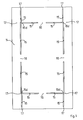
- the method according to the invention to make a container 10 which in this case is a fruit crate, or any other type of container, provides to use a plane panel 11 made of wood fibre or other composite material, such as MDF.
- the size of the panel 11, to make a crate 10 with a standardized base, that is, 290 x 490 mm, are as follows: width 410 mm, length 706 mm, thickness about 3-4 mm, in this case 3.2 mm.
- a plurality of through notches or slits 15 are made in the panel 11, with a constant width of about 5-6 mm, for example 5.5 mm.
- the notches 15 do not cause any part of the panel 11 to be completely detached.
- the median zones 16, arranged between pairs of adjacent notches 15, and the peripheral zones 17, arranged between the notches 15 and the outside of the panel 11, are kept without notches.
- the shearing operation can be performed with any conventional shearing machine.
- plastic material such as nylon, polypropylene, polyolefine or otherwise is injected into all the notches 15, to define inside each notch 15 a connection layer 30 between the different adjacent parts of the panel 11, which will later serve to form the container 10, as will be explained in detail later.
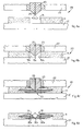
- the injection step is made by means of an injection press 20 (Figs. 4a to 4d), which comprises a base 21 on which the panel 11 is rested, and a mold 22 able to be arranged above the panel 11 and to impart thereon a very strong force, for example about 1.500.000 N.
- an injection press 20 Figs. 4a to 4d
- a mold 22 able to be arranged above the panel 11 and to impart thereon a very strong force, for example about 1.500.000 N.
- the pressure with which the mold 22 holds the panel 11 pressed against the base 20 prevents the panel from deforming during the injection step. Moreover, if, during the first shearing step, the notches 15 have been made without any break in continuity, from one edge of the panel 11 to the other, the pressure of the mold 22 also prevents the different parts of the panel 11 from moving from their original position, which is an essential condition for a correct injection step.
- the mold 22 is provided with one or more punches 23, each having the lower end pointed, V-shaped, and provided with one or more vertical injection channels 25, through which the plastic material is able to be injected under pressure.
- the angle at the top ⁇ (Fig. 4a) of the point of each punch 23 is advantageously equal to or a little more than 90°, for example 95°.
- each punch 23 is inserted into the corresponding notch 15 and divides it substantially into two parts, 15a and 15b, connected together in the intermediate zone 15c.
- the plastic material is then injected at high pressure and high temperature, for example about 200-800 bar and about 140°-260°C, through the channels 25 into the notches 15. With such pressure and temperature, the plastic material not only fills the zones 15a, 15b and 15c of the notches 15, but is also inserted into the adjacent parts of the panel 11 (Fig. 4c).
- the same plastic material is injected advantageously into the points 15d where three notches 15 meet (Fig. 1).
- the connecting layer 30 made of plastic material remains both in each notch 15, with a V-shaped upper groove 31, an angle at the top ⁇ equal to that of the punch 23 and into the adjacent parts of the panel 11, because the connecting layer 30 comprises also two lateral parts 30a and 30b, permanently inserted into the panel 11, and a join zone 30c with a thickness of about 1 mm.
- the join zones 30c constitute proper hinges between adjacent parts of the panel 11.
- a third possible working step is performed, which consists of another shearing, only in the case that, during the first shearing step, the median zones 16 and the peripheral zones 17 have been left without notches 15.
- both the median zones 16 and the peripheral zones 17, and also the lateral parts 18 are removed from the panel 11, so that the panel 11 is composed only of the parts used to make the crate 10 (Fig. 3).
- two eyelets 33 and two eyelets 34 are thus made, in place of the four median zones 16, four slits 35 in place of four peripheral zones 17, and two median fins 36 aligned with the eyelets 33.
- the parts to make up the crate 10 comprise a bottom wall 40, two long lateral walls 41 and 42, two short lateral walls 43 and 45, two first fins 43a and 43b of the lateral wall 43 and two second fins 45a and 45b of the lateral wall 45.
- the width of the long lateral walls 41 and 42 which will also be their height, is less than that of the shorter lateral walls 43 and 45.
- they are respectively 60 mm and 90 mm, excluding the median fins 36.
- the crate 10 can be completed by the user himself, and the following operations are required.
- the lateral walls 41 and 42 are inclined by 90° upwards, hinged in the corresponding layers 30, so as to be arranged one parallel to the other and perpendicular to the bottom wall 40.
- the fins 43a and 43b of the lateral wall 43 and the fins 45a and 45b of the lateral wall 45 are also then inclined by 90° upwards, so as to be arranged one parallel to the other and perpendicular to the lateral walls 43 and 45. Then the latter are inclined by 90° with respect to the bottom wall, thus arranging the fins 43a, 43b, 45a and 45b parallel to the lateral walls 41 and 42.
- fins 43a, 43b, 45a and 45b are attached to the lateral walls 41 and 42 by any conventional means, such as glue or attachment elements 50.
- the median fins 36 enter into the corresponding eyelets 33 and thus prevent the upper crate 10 from moving laterally with respect to the lower one.
- the lateral fins 41 and 42 are attached to the lateral fins 43 and 45 directly in correspondence with their edges, by means of any conventional means.
Abstract
Description
- The invention concerns a method to make containers such as boxes, fruit crates, containers for furniture or for personal use or otherwise, and the containers thus made. The lateral and bottom walls of the containers are advantageously made of wood fibres or composite materials, such as MDF or similar, and are obtained by shearing from a single base panel. The different lateral walls are joined to the bottom wall by injecting plastic material at high pressure into the shearing zones. The lateral walls are then bent by 90° with respect to the bottom wall and joined together using the fins of two opposite lateral walls, or directly on the edges, by means of glue or attachment elements. A corresponding cover can be associated with each container, also made using the method according to the invention.
- The state of the art includes various techniques to make containers, using cardboard, wood or metal.
- One known technique, disclosed in DE-U-81 27 771, provides to make both the bottom wall and the lateral walls by shearing from a single base panel made of wood fibre. The base panel is first glued to an additional sheet of paper or plastic material which is not sheared. Hinge zones are created in this way, consisting of the additional sheet and which allows to bend the different parts and to glue them or fix them together.
- Another known technique is to mill the lateral edges of the individual elements which make up the walls of the container with shaped mills, to create on the adjacent edges a first V-shaped groove, as deep as more than half the thickness of the elements and, in the remaining part of the thickness, a second, upside-down V-shaped groove. In this way substantially X-shaped grooves are formed which facilitate the coupling of the various walls at 90°.
- However, both these known techniques provide many working stages and/or the use of particular tools, which make the production process complex and costly.
- The US-A-6,286,198 discloses a method to form structure by folding a panel along one or more V-grooves cut in the inside surface of the panel. The verticies formed by the V-groove on the folded panel includes film hinges which are formed by injecting a plastic material in a groove formed on the outside surface of the panel. The plastic material simply fills the grooves and is in contact with the recessed region of the panel, so that the connection between the plastic material and the different parts of the panel is too weak and unstable.
- The present Applicant has devised the method to make containers according to the invention to overcome the shortcomings of the state of the art.
- The invention is set forth and characterized in the main claims, while the dependent claims describe other innovative characteristics of the invention.
- One purpose of the invention is to perfect a method which allows to make containers such as boxes, fruit crates, containers for furniture or for personal use or otherwise, in a simple fashion and at very limited cost.
- The method according to the invention provides that, to make a particular container, a substantially plane panel is used, for example made of wood fibre or composite material, such as that commonly known as MDF. The panel is advantageously several millimetres thick, for example from 2 to 10, and has a surface extension at least equal to the sum of the surface of the bottom wall and the surfaces of the lateral walls.
- The method according to the invention comprises a first step, or shearing step, in order to make first notches, advantageously through, which delimit what will be the lateral walls from what will be the bottom wall. The width of the notches is substantially constant, and advantageously is greater than the thickness of the plane panel, for example from 5 to 15 mm.
- According to a variant, the first notches have an area of discontinuity in particular zones of the panel, in order to keep the different parts which will make up the container joined together by zones of temporary union.
- Subsequently the method provides a second working step, or injection step, during which plastic material is injected into the previously made notches, advantageously at high pressure (from about 200 to about 800 bar) and at high temperature (from about 140°C to about 260°C); as it inserts itself between the wood fibres, the plastic material defines a connection layer between the adjacent edges of the parts of the panel, which acts as a joining element between two adjacent parts.
- In order to perform this injection, it is advantageous to use a punch which has a V-shaped end, so as to define a corresponding V-shaped groove in each connection layer.
- The depth of the V-shaped groove is advantageously less than the thickness of the panel but greater than half thereof, so that a zone of permanent join is also made between the two adjacent edges.
- In the event that, during the first shearing step, the zones of temporary join are left in the panel, between the different parts which will make up the container, a second shearing step is provided to make second notches in said zones of temporary join.
- Both the first and the possible second shearing step can be made, for example, with a shearing press or a pressure shear, with an alternating movement along an axis perpendicular to that on which the plane panel lies.
- At the end of the aforesaid working steps, the plane panel will be shaped, sheared and provided with the join elements. The latter, made of plastic material, arranged between the walls of the container cut out from the panel, constitute proper hinges which allow each part to be inclined up to 90° and more with respect to the adjacent one, while still remaining joined thereto.
- The method according to the invention also allows to achieve, advantageously and simultaneously with the other elements, two fins at the sides of two first opposite lateral walls, for example on the shortest walls, in the case of a container with a rectangular bottom wall. Once folded towards the inside of the container and arranged parallel with the other two lateral walls, the fins are joined to the latter so as to form in this way the four walls of the container. The join between the fins of the first two lateral walls and the other two lateral walls can be performed with any conventional means, such as for example by gluing or by attachment elements, commonly known as fasteners.
- Any type of container and the relative cover can be made with the method according to the invention.
- The method according to the invention has the considerable advantage that it essentially requires only two working steps (shearing and injection) to transform the plane panel into a combination of elements, sheared to size and hinged together, which by means of a further, simple operation of attaching the lateral walls, with or without fins, can be made into any container whatsoever.
- Furthermore, while the above-mentioned working steps are advantageously performed in an equipped site, the step to attach the lateral walls, and hence the final composition of the container, can be easily performed by the user when needed, thus greatly saving space and storage and transport costs.
- Moreover, should it be desired to make a fruit crate, during the second shearing step it is also possible to advantageously make two upper fins which, during use, can be inserted into corresponding eyelets made in the bottom wall of a similar container, in order to facilitate the piling of crates one on top of the other.
- These and other characteristics of the invention will be apparent from the following description of a preferential form of embodiment, given as a non-restrictive example with reference to the attached drawings wherein:
- Fig. 1
- is a plane view of a plane panel to make a container using the method according to the invention, shown after a first working step;
- Fig. 2
- is a plane view of the plane panel in Fig. 1, shown after a second working step;
- Fig. 3
- is a plane view of the plane panel in Fig. 1, shown after a possible third working step;
- Figs. 4a, 4b, 4c and 4d
- are side views, enlarged and partly in section, of a machine with which the second working step of the plane panel in Fig. 1 is performed;
- Fig. 5
- is a prospective view of a fruit crate made with the method according to the invention;
- Fig. 6
- is a first enlarged detail of Fig. 5;
- Fig. 7
- is a second enlarged detail of Fig. 5.
- With reference to Figs. 1 and 5, the method according to the invention to make a
container 10 , which in this case is a fruit crate, or any other type of container, provides to use aplane panel 11 made of wood fibre or other composite material, such as MDF. - The size of the
panel 11, to make acrate 10 with a standardized base, that is, 290 x 490 mm, are as follows: width 410 mm, length 706 mm, thickness about 3-4 mm, in this case 3.2 mm. - In a first working step, consisting of shearing, a plurality of through notches or
slits 15 are made in thepanel 11, with a constant width of about 5-6 mm, for example 5.5 mm. - To facilitate the subsequent working step, it is useful, though not essential for the purposes of the invention, that the
notches 15 do not cause any part of thepanel 11 to be completely detached. For this purpose, for example, themedian zones 16, arranged between pairs ofadjacent notches 15, and theperipheral zones 17, arranged between thenotches 15 and the outside of thepanel 11, are kept without notches. - The shearing operation can be performed with any conventional shearing machine.
- In a second working step, or injection step, plastic material such as nylon, polypropylene, polyolefine or otherwise is injected into all the
notches 15, to define inside eachnotch 15 aconnection layer 30 between the different adjacent parts of thepanel 11, which will later serve to form thecontainer 10, as will be explained in detail later. - The injection step is made by means of an injection press 20 (Figs. 4a to 4d), which comprises a base 21 on which the
panel 11 is rested, and amold 22 able to be arranged above thepanel 11 and to impart thereon a very strong force, for example about 1.500.000 N. - The pressure with which the
mold 22 holds thepanel 11 pressed against thebase 20 prevents the panel from deforming during the injection step. Moreover, if, during the first shearing step, thenotches 15 have been made without any break in continuity, from one edge of thepanel 11 to the other, the pressure of themold 22 also prevents the different parts of thepanel 11 from moving from their original position, which is an essential condition for a correct injection step. - The
mold 22 is provided with one ormore punches 23, each having the lower end pointed, V-shaped, and provided with one or morevertical injection channels 25, through which the plastic material is able to be injected under pressure. The angle at the top α (Fig. 4a) of the point of each punch 23 is advantageously equal to or a little more than 90°, for example 95°. - When the
mold 22 is in the lowered position (Fig. 4b), each punch 23 is inserted into the correspondingnotch 15 and divides it substantially into two parts, 15a and 15b, connected together in theintermediate zone 15c. - The plastic material is then injected at high pressure and high temperature, for example about 200-800 bar and about 140°-260°C, through the
channels 25 into thenotches 15. With such pressure and temperature, the plastic material not only fills thezones notches 15, but is also inserted into the adjacent parts of the panel 11 (Fig. 4c). - To distribute the plastic material better into the
notches 15 and into the adjacent parts of thepanel 11, the same plastic material is injected advantageously into thepoints 15d where threenotches 15 meet (Fig. 1). - Once the
mold 22 has been removed (Fig. 4d), the connectinglayer 30 made of plastic material remains both in eachnotch 15, with a V-shapedupper groove 31, an angle at the top α equal to that of thepunch 23 and into the adjacent parts of thepanel 11, because the connectinglayer 30 comprises also twolateral parts panel 11, and ajoin zone 30c with a thickness of about 1 mm. Thejoin zones 30c constitute proper hinges between adjacent parts of thepanel 11. - Once the plastic material of the
layers 30 has cooled and set, a third possible working step is performed, which consists of another shearing, only in the case that, during the first shearing step, themedian zones 16 and theperipheral zones 17 have been left withoutnotches 15. - To be more exact, both the
median zones 16 and theperipheral zones 17, and also the lateral parts 18 (all shown with a line of dashes in Fig. 2), are removed from thepanel 11, so that thepanel 11 is composed only of the parts used to make the crate 10 (Fig. 3). With the second shearing operation twoeyelets 33 and twoeyelets 34 are thus made, in place of the fourmedian zones 16, fourslits 35 in place of fourperipheral zones 17, and twomedian fins 36 aligned with theeyelets 33. - The parts to make up the
crate 10 comprise abottom wall 40, twolong lateral walls lateral walls first fins lateral wall 43 and twosecond fins lateral wall 45. - Since it is a fruit box, the width of the
long lateral walls lateral walls median fins 36. - The
crate 10 can be completed by the user himself, and the following operations are required. - The
lateral walls corresponding layers 30, so as to be arranged one parallel to the other and perpendicular to thebottom wall 40. - The
fins lateral wall 43 and thefins lateral wall 45 are also then inclined by 90° upwards, so as to be arranged one parallel to the other and perpendicular to thelateral walls fins lateral walls - Finally the
fins lateral walls attachment elements 50. - When the
crates 10 are piled up one on top of another, themedian fins 36 enter into the correspondingeyelets 33 and thus prevent theupper crate 10 from moving laterally with respect to the lower one. - According to a variant not shown in the drawings, instead of being attached by means of the
fins lateral fins lateral fins - With the method according to the invention, which as we have seen comprises only three working steps to transform the
basic panel 11 into a plurality ofparts layers 30 of plastic material, it is possible to make containers of any shape and size, and the relative covers. - It is clear that modifications or additions of steps or parts can be made to the method and
container 10 as described heretofore, without departing from the field and scope of the present invention. - It is also clear that, although the invention has been described with reference to a specific example, a skilled person in the field shall certainly be able to achieve many other equivalent forms, all of which shall come within the field and scope of the present invention.
Claims (1)
- Method to make containers (10) such as boxes, fruit crates, containers for furniture or for personal use or otherwise, each one having a bottom wall (40) and a plurality of lateral walls (41, 42, 43, 45), characterized in that it comprises at least a first shearing step to make in a substantially plane panel (11), having a surface extension at least equal to the sum of the surface of said bottom wall (40) and the surfaces of said lateral walls (41, 42, 43, 45), a plurality of notches (15) to delimit said bottom wall (40) from said lateral walls (41, 42, 43, 45), and a second injection step to inject plastic material both into said plurality of notches (15) and into the zones of said panel adjacent to said notches (15), in order to achieve connection layers (30) made of plastic material, functioning as a hinge between said bottom wall (40) and said lateral walls (41, 42, 43, 45), wherein said injection step is performed maintaining said panel (11) pressed with a force sufficient so that the latter is not deformed during the injection of said plastic material into the zones of said panel adjacent to said notches (15).Method as in claim 1, characterized in that said notches (15) comprise one or more discontinuities in predetermined zones (16, 17) of said panel (11), to maintain the different parts which will make up the container (10) joined together by zones of temporary join during said second injection step.Method as in claim 1 or 2, characterized in that said panel (11) is made of wood fibre or other composite material.Method as in any claim hereinbefore, characterized in that the plastic material is injected at high pressure and at high temperature.Method as in claim 4, characterized in that the injection pressure of said plastic material is between about 200 and about 800 bar.Method as in claim 4, characterized in that said plastic material is injected at a temperature of between about 140°C and about 260°C.Method as in any claim hereinbefore, characterized in that said notches (15) are through and are substantially constant in width.Method as in any claim hereinbefore, characterized in that the width of said notches (15) is greater than the thickness of said panel (11).Method as in claim 7 or 8, characterized in that the thickness of said panel (11) is between about 2 and about 10 mm and the width of said notches (15) is between about 5 and about 15 mm.Method as in any claim hereinbefore, characterized in that said injection step is made by means of injection means (20) comprising at least a base (21) on which said panel (11) is rested, and thrust means (22) able to thrust said panel (11) with said force against said base (21).Method as in claim 10, characterized in that said force is about 1.500.000 N.Method as in claim 10, characterized in that said injection means (20) also comprise at least a punch (23) with a pointed and V-shaped lower end, which is provided with at least an injection channel (25), through which said plastic material is able to be injected.Method as in claim 12, characterized in that the angle at the top (α) of the point of said punch (23) is equal to or slightly more than 90°.Method as in claim 12, characterized in that, for the injection of said plastic material, said injection channel (25) is positioned in the meeting points (15d) between at least two of said notches (15).Method as in any claim hereinbefore, characterized in that each of said connection layers (30) made of plastic material comprises a V-shaped groove (31) which defines two lateral parts (30a and 30b) permanently connected to said panel (11) and a join zone (30c) which constitutes a hinge between adjacent parts of said panel (11).Method as in claim 15, characterized in that the thickness of said join zone (30c) is about 1 mm.Method as in claim 13 or 15, characterized in that the angle of said groove (31) is substantially equal to the angle at the top (α) of said punch (23).Method as in claim 2, characterized in that said discontinuities (16, 17) are eliminated after said second injection step has been completed so that said panel (11) is composed of only the parts useful to make said container (10).Method as in claim 18, characterized in that said discontinuities (16, 17) are eliminated by means of shearing which makes a plurality of through apertures (33, 34, 35) in their place.Container such as a box, a fruit crate, a drawer for furniture or otherwise, comprising a bottom wall (40) and a plurality of lateral walls (41, 42, 43, 45), characterized in that a connection layer (30) made of plastic material, functioning as a hinge, is disposed both between at least one of said lateral walls (41, 42, 43, 45) and said bottom wall (40), and also partially inside said walls (40, 41, 42, 43, 45).Container as in claim 21, characterized in that said connection layer (30) is disposed between each one of said lateral walls (41, 42, 43, 45) and said bottom wall (40).Container as in claim 21 or 22, characterized in that said connection layers (30) made of plastic material are made according to the method as in any one of the claims from 1 to 19 inclusive.Container as in claim 20, 21 or 22, characterized in that said lateral walls comprise two first lateral walls (41, 42) parallel to each other and two second lateral walls (43, 45) perpendicular to said first lateral walls (41, 42), said second lateral walls (43, 45) being provided with fins (43a, 43b and 45a, 45b) disposed parallel and attached to said first lateral walls (41, 42).Container as in claim 23, characterized in that connection layers (30) made of plastic material are also provided between said second lateral walls (43, 45) and said fins (43a, 43b and 45a, 45b).
Applications Claiming Priority (2)
| Application Number | Priority Date | Filing Date | Title |
|---|---|---|---|
| ITUD20010202 | 2001-12-05 | ||
| IT2001UD000202A ITUD20010202A1 (en) | 2001-12-05 | 2001-12-05 | METHOD FOR MANUFACTURING CONTAINERS, SUCH AS BOXES, FRUIT BOXES, CONTAINERS FOR FURNITURE OR FOR PERSONAL USE OR OTHERWISE AND CONTAINERS |
Publications (3)
| Publication Number | Publication Date |
|---|---|
| EP1325799A1 EP1325799A1 (en) | 2003-07-09 |
| EP1325799A9 true EP1325799A9 (en) | 2004-03-31 |
| EP1325799B1 EP1325799B1 (en) | 2006-11-08 |
Family
ID=11460665
Family Applications (1)
| Application Number | Title | Priority Date | Filing Date |
|---|---|---|---|
| EP02027125A Expired - Lifetime EP1325799B1 (en) | 2001-12-05 | 2002-12-04 | Method to make containers, such as boxes, fruit crates, containers for furniture or personal use or otherwise, and containers thus made |
Country Status (5)
| Country | Link |
|---|---|
| EP (1) | EP1325799B1 (en) |
| AT (1) | ATE344721T1 (en) |
| DE (1) | DE60215908D1 (en) |
| ES (1) | ES2276886T3 (en) |
| IT (1) | ITUD20010202A1 (en) |
Cited By (1)
| Publication number | Priority date | Publication date | Assignee | Title |
|---|---|---|---|---|
| AT500272B1 (en) * | 2003-06-06 | 2006-11-15 | Ib Steiner Ingenieurbuero Fuer | PROCESS FOR CONNECTING BASE ELEMENTS FROM SOLID WOOD WITH PLASTIC |
Families Citing this family (5)
| Publication number | Priority date | Publication date | Assignee | Title |
|---|---|---|---|---|
| WO2010004059A1 (en) * | 2008-07-08 | 2010-01-14 | Cartonajes International, S.L., Sociedad Unipersonal | Corrugated cardboard box for transporting fish or perishable products, method for sealing said box and means for implementing said method |
| ES2340652B1 (en) * | 2008-10-31 | 2011-05-12 | Telesforo Gonzalez Olmos | APPARATUS AND METHOD FOR SEALING EDGE OF HOLES IN CORRUGATED CARTON PLATES. |
| IT1398623B1 (en) | 2010-03-10 | 2013-03-08 | Cintio | PACKAGING, IN PARTICULAR FOR SPELLING AND RELATIVE PRODUCTION PROCESS |
| DE102015219103A1 (en) * | 2015-10-02 | 2017-04-06 | Weeke Bohrsysteme Gmbh | Device for forming attachments |
| CN108749110A (en) * | 2018-06-11 | 2018-11-06 | 张家港市德昶自动化科技有限公司 | Automatic graphite papery cover board molding machine |
Family Cites Families (3)
| Publication number | Priority date | Publication date | Assignee | Title |
|---|---|---|---|---|
| US3571857A (en) * | 1969-08-14 | 1971-03-23 | Jeff S Rhyne | Fastening apparatus |
| DE4418274C2 (en) * | 1994-05-26 | 1997-11-27 | Bhf Beschichtungswerk B Hagedo | Board, especially hardboard |
| ES2191991T3 (en) * | 1998-03-18 | 2003-09-16 | Wilhelm Riesmeier | PROCEDURE FOR THE MANUFACTURE OF FURNITURE STRUCTURES. |
-
2001
- 2001-12-05 IT IT2001UD000202A patent/ITUD20010202A1/en unknown
-
2002
- 2002-12-04 ES ES02027125T patent/ES2276886T3/en not_active Expired - Lifetime
- 2002-12-04 DE DE60215908T patent/DE60215908D1/en not_active Expired - Lifetime
- 2002-12-04 EP EP02027125A patent/EP1325799B1/en not_active Expired - Lifetime
- 2002-12-04 AT AT02027125T patent/ATE344721T1/en not_active IP Right Cessation
Cited By (1)
| Publication number | Priority date | Publication date | Assignee | Title |
|---|---|---|---|---|
| AT500272B1 (en) * | 2003-06-06 | 2006-11-15 | Ib Steiner Ingenieurbuero Fuer | PROCESS FOR CONNECTING BASE ELEMENTS FROM SOLID WOOD WITH PLASTIC |
Also Published As
| Publication number | Publication date |
|---|---|
| ES2276886T3 (en) | 2007-07-01 |
| ATE344721T1 (en) | 2006-11-15 |
| EP1325799B1 (en) | 2006-11-08 |
| EP1325799A1 (en) | 2003-07-09 |
| DE60215908D1 (en) | 2006-12-21 |
| ITUD20010202A1 (en) | 2002-07-11 |
Similar Documents
| Publication | Publication Date | Title |
|---|---|---|
| US6520898B1 (en) | Process of making a compartmented container | |
| US8794463B2 (en) | Self-assemblable container for generic use and manufacturing method thereof | |
| EP1089912B1 (en) | Airtight food packaging and a method and tray for the production thereof | |
| US5211618A (en) | Self-centering laminated process for corrugated containers and blank therefor | |
| DE1561550A1 (en) | Container element, pack, and form and method for manufacturing the container element | |
| AU2016210737A1 (en) | Corrugated pallet constructed of folded, interlocked blanks and method | |
| US5092467A (en) | Shipping and display container | |
| US6216871B1 (en) | Package and method for packaging of batches of articles of undetermined volume | |
| NZ513459A (en) | Collapsible crate and associated connecting means | |
| EP1325799B1 (en) | Method to make containers, such as boxes, fruit crates, containers for furniture or personal use or otherwise, and containers thus made | |
| EP1089922B1 (en) | Sales packaging | |
| EP0653354B1 (en) | Package for books and/or other products, and process and device for its manufacture | |
| US4001471A (en) | Thermoplastic seam between juxtaposed edges of blank material | |
| DE4114163C2 (en) | Process for the manufacture of packaging for shock-sensitive consumer goods, and packaging produced thereafter | |
| EP0709297B1 (en) | One-piece corrugated tray | |
| DE3034363A1 (en) | Sales display pack folded from cardboard blank - has flat rear panel glued to side panels and flaps,and front panel with display window | |
| EP1505001B1 (en) | Process for manufacturing a box-shaped container made of thermoplastic material | |
| EP0409366A2 (en) | Parallelepipedic package made of foldable material | |
| DE3442439C2 (en) | ||
| US4197788A (en) | Method of cutting and assembling a carton | |
| DE102004003246A1 (en) | Pedestal for display stand is made from single cardboard blank which can be assembled to hollow box shape and has inner walls attached to tops of outer walls by connecting strips which fold down inside them to reinforce box | |
| EP0172932A1 (en) | Package blank made of carton or the same, to make a package body | |
| GB2080251A (en) | Carton with separaters | |
| JPH0329740A (en) | Method and device to seal liquid package | |
| EP0316890B1 (en) | Prefolded blank of one piece made of pliable material for a cup-tray |
Legal Events
| Date | Code | Title | Description |
|---|---|---|---|
| PUAI | Public reference made under article 153(3) epc to a published international application that has entered the european phase |
Free format text: ORIGINAL CODE: 0009012 |
|
| AK | Designated contracting states |
Designated state(s): AT BE BG CH CY CZ DE DK EE ES FI FR GB GR IE IT LI LU MC NL PT SE SI SK TR |
|
| AX | Request for extension of the european patent |
Extension state: AL LT LV MK RO SI |
|
| 17P | Request for examination filed |
Effective date: 20040108 |
|
| AKX | Designation fees paid |
Designated state(s): AT BE BG CH CY CZ DE DK EE ES FI FR GB GR IE IT LI LU MC NL PT SE SI SK TR |
|
| 17Q | First examination report despatched |
Effective date: 20050114 |
|
| GRAP | Despatch of communication of intention to grant a patent |
Free format text: ORIGINAL CODE: EPIDOSNIGR1 |
|
| GRAS | Grant fee paid |
Free format text: ORIGINAL CODE: EPIDOSNIGR3 |
|
| GRAA | (expected) grant |
Free format text: ORIGINAL CODE: 0009210 |
|
| AK | Designated contracting states |
Kind code of ref document: B1 Designated state(s): AT BE BG CH CY CZ DE DK EE ES FI FR GB GR IE IT LI LU MC NL PT SE SI SK TR |
|
| PG25 | Lapsed in a contracting state [announced via postgrant information from national office to epo] |
Ref country code: AT Free format text: LAPSE BECAUSE OF FAILURE TO SUBMIT A TRANSLATION OF THE DESCRIPTION OR TO PAY THE FEE WITHIN THE PRESCRIBED TIME-LIMIT Effective date: 20061108 Ref country code: SI Free format text: LAPSE BECAUSE OF FAILURE TO SUBMIT A TRANSLATION OF THE DESCRIPTION OR TO PAY THE FEE WITHIN THE PRESCRIBED TIME-LIMIT Effective date: 20061108 Ref country code: FI Free format text: LAPSE BECAUSE OF FAILURE TO SUBMIT A TRANSLATION OF THE DESCRIPTION OR TO PAY THE FEE WITHIN THE PRESCRIBED TIME-LIMIT Effective date: 20061108 Ref country code: LI Free format text: LAPSE BECAUSE OF FAILURE TO SUBMIT A TRANSLATION OF THE DESCRIPTION OR TO PAY THE FEE WITHIN THE PRESCRIBED TIME-LIMIT Effective date: 20061108 Ref country code: NL Free format text: LAPSE BECAUSE OF FAILURE TO SUBMIT A TRANSLATION OF THE DESCRIPTION OR TO PAY THE FEE WITHIN THE PRESCRIBED TIME-LIMIT Effective date: 20061108 Ref country code: SK Free format text: LAPSE BECAUSE OF FAILURE TO SUBMIT A TRANSLATION OF THE DESCRIPTION OR TO PAY THE FEE WITHIN THE PRESCRIBED TIME-LIMIT Effective date: 20061108 Ref country code: CZ Free format text: LAPSE BECAUSE OF FAILURE TO SUBMIT A TRANSLATION OF THE DESCRIPTION OR TO PAY THE FEE WITHIN THE PRESCRIBED TIME-LIMIT Effective date: 20061108 Ref country code: BE Free format text: LAPSE BECAUSE OF FAILURE TO SUBMIT A TRANSLATION OF THE DESCRIPTION OR TO PAY THE FEE WITHIN THE PRESCRIBED TIME-LIMIT Effective date: 20061108 Ref country code: CH Free format text: LAPSE BECAUSE OF FAILURE TO SUBMIT A TRANSLATION OF THE DESCRIPTION OR TO PAY THE FEE WITHIN THE PRESCRIBED TIME-LIMIT Effective date: 20061108 |
|
| REG | Reference to a national code |
Ref country code: GB Ref legal event code: FG4D |
|
| REG | Reference to a national code |
Ref country code: CH Ref legal event code: EP |
|
| PG25 | Lapsed in a contracting state [announced via postgrant information from national office to epo] |
Ref country code: IE Free format text: LAPSE BECAUSE OF NON-PAYMENT OF DUE FEES Effective date: 20061204 |
|
| REG | Reference to a national code |
Ref country code: IE Ref legal event code: FG4D |
|
| REF | Corresponds to: |
Ref document number: 60215908 Country of ref document: DE Date of ref document: 20061221 Kind code of ref document: P |
|
| PG25 | Lapsed in a contracting state [announced via postgrant information from national office to epo] |
Ref country code: MC Free format text: LAPSE BECAUSE OF NON-PAYMENT OF DUE FEES Effective date: 20061231 |
|
| PG25 | Lapsed in a contracting state [announced via postgrant information from national office to epo] |
Ref country code: DK Free format text: LAPSE BECAUSE OF FAILURE TO SUBMIT A TRANSLATION OF THE DESCRIPTION OR TO PAY THE FEE WITHIN THE PRESCRIBED TIME-LIMIT Effective date: 20070208 Ref country code: SE Free format text: LAPSE BECAUSE OF FAILURE TO SUBMIT A TRANSLATION OF THE DESCRIPTION OR TO PAY THE FEE WITHIN THE PRESCRIBED TIME-LIMIT Effective date: 20070208 Ref country code: BG Free format text: LAPSE BECAUSE OF FAILURE TO SUBMIT A TRANSLATION OF THE DESCRIPTION OR TO PAY THE FEE WITHIN THE PRESCRIBED TIME-LIMIT Effective date: 20070208 |
|
| PG25 | Lapsed in a contracting state [announced via postgrant information from national office to epo] |
Ref country code: DE Free format text: LAPSE BECAUSE OF FAILURE TO SUBMIT A TRANSLATION OF THE DESCRIPTION OR TO PAY THE FEE WITHIN THE PRESCRIBED TIME-LIMIT Effective date: 20070209 |
|
| PG25 | Lapsed in a contracting state [announced via postgrant information from national office to epo] |
Ref country code: PT Free format text: LAPSE BECAUSE OF FAILURE TO SUBMIT A TRANSLATION OF THE DESCRIPTION OR TO PAY THE FEE WITHIN THE PRESCRIBED TIME-LIMIT Effective date: 20070409 |
|
| NLV1 | Nl: lapsed or annulled due to failure to fulfill the requirements of art. 29p and 29m of the patents act | ||
| ET | Fr: translation filed | ||
| REG | Reference to a national code |
Ref country code: CH Ref legal event code: PL |
|
| REG | Reference to a national code |
Ref country code: ES Ref legal event code: FG2A Ref document number: 2276886 Country of ref document: ES Kind code of ref document: T3 |
|
| PLBE | No opposition filed within time limit |
Free format text: ORIGINAL CODE: 0009261 |
|
| STAA | Information on the status of an ep patent application or granted ep patent |
Free format text: STATUS: NO OPPOSITION FILED WITHIN TIME LIMIT |
|
| 26N | No opposition filed |
Effective date: 20070809 |
|
| GBPC | Gb: european patent ceased through non-payment of renewal fee |
Effective date: 20070208 |
|
| PGFP | Annual fee paid to national office [announced via postgrant information from national office to epo] |
Ref country code: IT Payment date: 20071219 Year of fee payment: 6 |
|
| PG25 | Lapsed in a contracting state [announced via postgrant information from national office to epo] |
Ref country code: GR Free format text: LAPSE BECAUSE OF FAILURE TO SUBMIT A TRANSLATION OF THE DESCRIPTION OR TO PAY THE FEE WITHIN THE PRESCRIBED TIME-LIMIT Effective date: 20070209 Ref country code: GB Free format text: LAPSE BECAUSE OF NON-PAYMENT OF DUE FEES Effective date: 20070208 |
|
| PGFP | Annual fee paid to national office [announced via postgrant information from national office to epo] |
Ref country code: ES Payment date: 20071228 Year of fee payment: 6 |
|
| PG25 | Lapsed in a contracting state [announced via postgrant information from national office to epo] |
Ref country code: EE Free format text: LAPSE BECAUSE OF FAILURE TO SUBMIT A TRANSLATION OF THE DESCRIPTION OR TO PAY THE FEE WITHIN THE PRESCRIBED TIME-LIMIT Effective date: 20061108 |
|
| PGFP | Annual fee paid to national office [announced via postgrant information from national office to epo] |
Ref country code: TR Payment date: 20071204 Year of fee payment: 6 |
|
| PG25 | Lapsed in a contracting state [announced via postgrant information from national office to epo] |
Ref country code: LU Free format text: LAPSE BECAUSE OF NON-PAYMENT OF DUE FEES Effective date: 20061204 |
|
| PGFP | Annual fee paid to national office [announced via postgrant information from national office to epo] |
Ref country code: FR Payment date: 20071217 Year of fee payment: 6 |
|
| PG25 | Lapsed in a contracting state [announced via postgrant information from national office to epo] |
Ref country code: CY Free format text: LAPSE BECAUSE OF FAILURE TO SUBMIT A TRANSLATION OF THE DESCRIPTION OR TO PAY THE FEE WITHIN THE PRESCRIBED TIME-LIMIT Effective date: 20061108 |
|
| REG | Reference to a national code |
Ref country code: FR Ref legal event code: ST Effective date: 20090831 |
|
| REG | Reference to a national code |
Ref country code: ES Ref legal event code: FD2A Effective date: 20081205 |
|
| PG25 | Lapsed in a contracting state [announced via postgrant information from national office to epo] |
Ref country code: FR Free format text: LAPSE BECAUSE OF NON-PAYMENT OF DUE FEES Effective date: 20081231 Ref country code: ES Free format text: LAPSE BECAUSE OF NON-PAYMENT OF DUE FEES Effective date: 20081205 |
|
| PG25 | Lapsed in a contracting state [announced via postgrant information from national office to epo] |
Ref country code: TR Free format text: LAPSE BECAUSE OF NON-PAYMENT OF DUE FEES Effective date: 20100928 |
|
| PG25 | Lapsed in a contracting state [announced via postgrant information from national office to epo] |
Ref country code: TR Free format text: LAPSE BECAUSE OF NON-PAYMENT OF DUE FEES Effective date: 20081204 |
|
| PG25 | Lapsed in a contracting state [announced via postgrant information from national office to epo] |
Ref country code: IT Free format text: LAPSE BECAUSE OF NON-PAYMENT OF DUE FEES Effective date: 20081204 |