EP1325690A2 - Mounting structure for buckles cord locks and the like - Google Patents
Mounting structure for buckles cord locks and the like Download PDFInfo
- Publication number
- EP1325690A2 EP1325690A2 EP02029017A EP02029017A EP1325690A2 EP 1325690 A2 EP1325690 A2 EP 1325690A2 EP 02029017 A EP02029017 A EP 02029017A EP 02029017 A EP02029017 A EP 02029017A EP 1325690 A2 EP1325690 A2 EP 1325690A2
- Authority
- EP
- European Patent Office
- Prior art keywords
- base
- attachment structure
- legs
- receivers
- rack
- Prior art date
- Legal status (The legal status is an assumption and is not a legal conclusion. Google has not performed a legal analysis and makes no representation as to the accuracy of the status listed.)
- Granted
Links
Images


Classifications
-
- A—HUMAN NECESSITIES
- A44—HABERDASHERY; JEWELLERY
- A44B—BUTTONS, PINS, BUCKLES, SLIDE FASTENERS, OR THE LIKE
- A44B99/00—Subject matter not provided for in other groups of this subclass
-
- A—HUMAN NECESSITIES
- A44—HABERDASHERY; JEWELLERY
- A44B—BUTTONS, PINS, BUCKLES, SLIDE FASTENERS, OR THE LIKE
- A44B11/00—Buckles; Similar fasteners for interconnecting straps or the like, e.g. for safety belts
- A44B11/006—Attachment of buckle to strap
-
- Y—GENERAL TAGGING OF NEW TECHNOLOGICAL DEVELOPMENTS; GENERAL TAGGING OF CROSS-SECTIONAL TECHNOLOGIES SPANNING OVER SEVERAL SECTIONS OF THE IPC; TECHNICAL SUBJECTS COVERED BY FORMER USPC CROSS-REFERENCE ART COLLECTIONS [XRACs] AND DIGESTS
- Y10—TECHNICAL SUBJECTS COVERED BY FORMER USPC
- Y10T—TECHNICAL SUBJECTS COVERED BY FORMER US CLASSIFICATION
- Y10T24/00—Buckles, buttons, clasps, etc.
- Y10T24/14—Bale and package ties, hose clamps
- Y10T24/1412—Bale and package ties, hose clamps with tighteners
- Y10T24/1418—Self-locking [dead center or snap action]
- Y10T24/142—Adjustable girth
- Y10T24/1422—Rack bar
-
- Y—GENERAL TAGGING OF NEW TECHNOLOGICAL DEVELOPMENTS; GENERAL TAGGING OF CROSS-SECTIONAL TECHNOLOGIES SPANNING OVER SEVERAL SECTIONS OF THE IPC; TECHNICAL SUBJECTS COVERED BY FORMER USPC CROSS-REFERENCE ART COLLECTIONS [XRACs] AND DIGESTS
- Y10—TECHNICAL SUBJECTS COVERED BY FORMER USPC
- Y10T—TECHNICAL SUBJECTS COVERED BY FORMER US CLASSIFICATION
- Y10T24/00—Buckles, buttons, clasps, etc.
- Y10T24/45—Separable-fastener or required component thereof [e.g., projection and cavity to complete interlock]
- Y10T24/45225—Separable-fastener or required component thereof [e.g., projection and cavity to complete interlock] including member having distinct formations and mating member selectively interlocking therewith
- Y10T24/45471—Projection having movable connection between components thereof or variable configuration
- Y10T24/45524—Projection having movable connection between components thereof or variable configuration including resiliently biased projection component or surface segment
- Y10T24/45529—Requiring manual force applied against bias to interlock or disengage
- Y10T24/45534—Requiring manual force applied against bias to interlock or disengage having connected leading edge and separated trailing arms
-
- Y—GENERAL TAGGING OF NEW TECHNOLOGICAL DEVELOPMENTS; GENERAL TAGGING OF CROSS-SECTIONAL TECHNOLOGIES SPANNING OVER SEVERAL SECTIONS OF THE IPC; TECHNICAL SUBJECTS COVERED BY FORMER USPC CROSS-REFERENCE ART COLLECTIONS [XRACs] AND DIGESTS
- Y10—TECHNICAL SUBJECTS COVERED BY FORMER USPC
- Y10T—TECHNICAL SUBJECTS COVERED BY FORMER US CLASSIFICATION
- Y10T24/00—Buckles, buttons, clasps, etc.
- Y10T24/45—Separable-fastener or required component thereof [e.g., projection and cavity to complete interlock]
- Y10T24/45225—Separable-fastener or required component thereof [e.g., projection and cavity to complete interlock] including member having distinct formations and mating member selectively interlocking therewith
- Y10T24/45471—Projection having movable connection between components thereof or variable configuration
- Y10T24/45524—Projection having movable connection between components thereof or variable configuration including resiliently biased projection component or surface segment
- Y10T24/45545—Projection having movable connection between components thereof or variable configuration including resiliently biased projection component or surface segment forming total external surface of projection
- Y10T24/45581—Projection having movable connection between components thereof or variable configuration including resiliently biased projection component or surface segment forming total external surface of projection having inserted end formed by oppositely biased surface segments
-
- Y—GENERAL TAGGING OF NEW TECHNOLOGICAL DEVELOPMENTS; GENERAL TAGGING OF CROSS-SECTIONAL TECHNOLOGIES SPANNING OVER SEVERAL SECTIONS OF THE IPC; TECHNICAL SUBJECTS COVERED BY FORMER USPC CROSS-REFERENCE ART COLLECTIONS [XRACs] AND DIGESTS
- Y10—TECHNICAL SUBJECTS COVERED BY FORMER USPC
- Y10T—TECHNICAL SUBJECTS COVERED BY FORMER US CLASSIFICATION
- Y10T24/00—Buckles, buttons, clasps, etc.
- Y10T24/45—Separable-fastener or required component thereof [e.g., projection and cavity to complete interlock]
- Y10T24/45225—Separable-fastener or required component thereof [e.g., projection and cavity to complete interlock] including member having distinct formations and mating member selectively interlocking therewith
- Y10T24/45602—Receiving member includes either movable connection between interlocking components or variable configuration cavity
- Y10T24/45623—Receiving member includes either movable connection between interlocking components or variable configuration cavity and operator therefor
Definitions
- the present invention relates generally to mounting structures, and more particularly to mounting structures having utility in applications such as, for example, buckles and cord locks used on clothing, sporting gear, luggage, safety equipment and the like.
- buckles, cord locks and other assemblies are known, with applications thereof in many different constructions, including, for example, clothing, sporting gear, luggage, safety and other equipment and the like.
- Two-part buckle assemblies are known in a variety of different constructions.
- cooperating first and second buckle pieces are provided with parts having interlocking components, allowing releasable locking engagement of the components.
- Cord locks are known for securing cords used in openings of bags, as cinctures on waistbands and cuffs, as draw strings for hoods, as well as numerous other applications.
- a female buckle component attached to one part of an article, and a male buckle component attached to another part of the article.
- the female component may be anchored to a bag or luggage, and the male component attached directly to a lid, cover or flap of the bag or luggage.
- one or both of the components may be attached to a strap or the like.
- a cord lock may be carried directly on the cord or may be anchored directly to the article or to a strap, lanyard or the like that is attached to the article.
- Attachment of the various components for cord locks, buckles and the like to the article on which they are used has been accomplished by a variety of different means, including sewing, gluing, physical attachment and the like.
- One of the problems associated therewith is that the attachment technique can be complicated and time consuming, thus adding to the time and expense of manufacture.
- Another problem can occur if the component, which often is made of plastic, breaks or otherwise becomes non-functional. Removal of the broken component can be difficult, and attachment of a replacement component can be time consuming. Buckles designed for one application may not be useful readily on another article for another application, particularly if the various articles are of different thickness. Thus, it is necessary to manufacture and store many different components suitable for anchoring on different articles.
- the present invention provides an anchoring or mounting structure that is useful for buckles, cord locks and the like, that includes first and second parts disposed on opposite sides of the article to which it is secured. Legs from one of the parts extend through the article and are connected to the other part by a variable attachment structure accommodating different article thickness.
- the present invention provides, in one form thereof, an adjustable attachment structure with a body and a base.
- One of the body and the base has a plurality of legs projecting outwardly therefrom.
- the other of the body and the base has receivers for accepting at least a portion of each leg.
- a first connector part is associated with the plurality of legs.
- a second connector part is associated with the receivers.
- the first and second connector parts are adapted for cooperative association to connect to each other and fix a spaced relation between the body and the base at a plurality of locations, establishing different distances between the body and the base.
- the present invention provides an attachment structure with a body and a base.
- One of the body and the base has a plurality of slots therein, each slot having an entrance on a same side of the base.
- Each slot defines a rack angling inwardly in the base from the entrance.
- the other of the body and the base has legs extending outwardly therefrom.
- Each leg has a distal end and a foot at the distal end.
- Each foot is designed to slide in one of the slots, with the legs configured to engage the racks at discrete locations along the lengths thereof.
- the invention provides an attachment structure with a body and a base discrete from the body.
- One of the body and the base has a plurality of legs extending outwardly therefrom.
- the other of the body and the base has receivers each adapted and arranged for receiving one of the legs inserted therein.
- One of the legs and the receivers defines racks along lengths thereof, and the other of the legs and the receivers defines lugs for engaging the racks.
- An advantage of the present invention is providing an attachment structure useful for mounting buckles, cord locks and other components on a variety of articles of differing thickness.
- a further advantage of the present invention is providing a mounting structure that attaches to a variety of articles quickly and easily.
- Yet another advantage of the present invention is providing a mounting structure for buckles, cord locks and the like that attaches securely, but can be readily detachable if the component requires replacement.
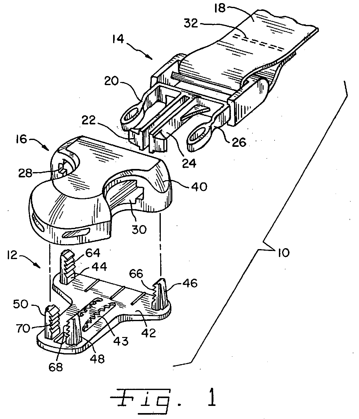
- Buckle assembly 10 includes a male component 14 that can be received and releasably locked in a female component 16.
- Buckle assembly 10 can be associated with a variety of different articles, such as luggage, clothing, safety equipment or the like.
- Male component 14 is attached to one article or part of an article and, as illustrated, is shown attached to a strap 18.
- Female component 16 is anchored to another article or part of an article (not shown in Fig. 1).
- male component 14 includes forward projecting arms 20, 22, 24 and 26 that are received in an aperture or apertures in female component 16. Outer arms 20 and 26 deflect inwardly as male component 14 is inserted in female component 16, and spring outwardly to be exposed through windows 28 and 30 of female component 16, as male component 14 is fully inserted. Male component 14 is released from female component 16 by squeezing inwardly on outer arms 20 and 26 while urging male component 14 and female component 16 in opposite directions.
- female component 16 includes attachment structure 12 for attaching female component 16 to an article (not shown in Fig. 1). While male component 14 is shown attached to strap 18 by a stitched seam 32, those skilled in the art will understand readily that connection of male component 14 to strap 18 or to another article (not shown) can be achieved also by employing the concepts and features of the present invention.
- Female component 16 includes a body 40 and a base 42 that connect to each other.
- Body 40 defines windows 28 and 30 and generally the structure necessary for receiving male component 14.
- One of body 40 and base 42 includes a plurality of legs 44, 46, 48 and 50, and as illustrated in the embodiment shown, base 42 includes four legs 44, 46, 48 and 50.
- the other of body 40 and base 42 includes a receiver 54, 56, 58, 60 (Fig. 2) for each leg 44, 46, 48, 50, and in the embodiment illustrated body 40 includes four receivers 54, 56, 58 and 60.
- base 42 includes a connector portion 43, preferably a toothed member or toothed leaf spring that is adapted to cooperate with an article (not shown in Fig. 1).
- body 40 includes an insertion guide portion 44 (Fig. 2) that is preferably angled downwardly towards the base 42 when assembled to prevent wear of the mating article (not shown in Fig. 1) during repeated assembly of the male component 14.
- a first connector part in the nature of a rack 64, 66, 68, 70 is provided for each leg 44, 46, 48, 50.
- a second connector part in the nature of a lug or lip 74, 76, 78 and 80 is provided in each receiver 54, 56, 58 and 60, respectively.
- Legs 44, 46, 48, 50 are structured and arranged on base 42, projecting outwardly therefrom so as to be received in receivers 54, 56, 58 and 60 of body 40, with lugs 74, 76, 78 and 80 selectively engageable along the lengths of racks 64, 66, 68 and 70, respectively.
- Base 42 and the associated legs 44, 46, 48 and 50 are arranged and configured so as not to undesirably interfere with the insertion or release of the arms 20, 22, 24 and 26 of the male component 14.
- the legs 44, 46, 48 and 50 are arranged and configured to be hidden or captured within the associated body 40 or base 42. Preferably, the legs would be hidden from view.
- Attachment structure 12 can be modified in a variety of ways to accommodate components other than male component 14 or female component 16 or different configurations thereof. Further, attachment structure 12 is suited for modification to accommodate different articles on which it is to be attached.
- Figs. 3-5 illustrate a second embodiment in the way of an attachment structure 90 wherein legs 92, 94 and 96 are provided on a body 98, and receivers 102, 104, 106 are provided on a base 108.
- Base 108 is a relatively flat, plate-like structure.
- Receivers 102, 104, 106 are formed as slots in base 108 and define racks 110, 112, 114 and 116 on side walls thereof.
- Slot-type receiver 106 is shown with two of racks 114 and 116 provided on opposite sides thereof.
- receiver 106 can be provided with only one rack 114 or 116, and/or receivers 102 or 104 can be provided with two racks on opposite sides thereof.
- Receivers 102, 104 and 106 have entrance openings 118, 120, 122, respectively, each provided in a same side 124 of base 108. Receivers 102, 104, 106, including racks 110, 112, 114 and 116 angle inwardly in base 108 from side 124.
- Legs 92, 94, 96 each include a foot 126, 128, 130, respectively, on distal ends thereof, which enter receivers 102, 104 and 106 through entrance openings 118, 120 and 122, respectively, as body 98 is attached to base 108.
- Feet 126, 128 and 130 are wider than slot-type receivers 102, 104 and 106 inwardly from entrance openings 118, 120 and 122, such that body 98 and base 108 can not be pulled apart unless feet 126, 128 and 130 are positioned in entrance openings 118, 120 and 122.
- Legs 92, 94, 96 each define or function as a lug or lip, with edges thereof that engage along racks 110 and 112, 114, 116, respectively.
- a plurality of openings 143 are shown which are simply provided to minimize material.
- the base 108 can be modified to include the connector portion 43 as shown and described with reference to Fig. 1. It should be understood that other connector portions can be utilized in accordance with the principles of the present invention.
- FIGs. 6, 7 and 8 illustrate a third embodiment in the way of an attachment structure 140 in accordance with the present invention.
- Attachment structure 140 is provided for a cord lock 142 having a body 144 and a base 146.
- Body 144 defines an aperture 148, and may include internal apparatus (not shown) for securing a cord (not shown) extended therethrough.
- Body 144 further includes legs 150 and 152, each having a foot 154, 156, respectively, on a distal end thereof.
- Slot-type receivers 158 and 160 are provided in base 146, and each defines a top rack 162 and a side rack 164 inwardly from respective entrance openings 166 and 168 thereof.
- Slot type receivers 158 and 160, and racks 162 and 164 defined thereby angle inwardly in base 146 from the surface thereof defining entrance openings 166 and 168.
- Lugs 170 and 172 on legs 150 and 152 engage side racks 164 in each receivers158, 160, and feet 154, 156 engaging along top racks 162 in each receiver 158, 160, as feet 154, 156 are slid inwardly in slot-type receivers 158 and 160.
- FIG. 6 illustrates the manner in which embodiment 140 is secured to an article 180.
- a hole or opening 182 is provided in article 180 for each leg 150, 152.
- Legs 150 and 152 are inserted through holes 182, such that feet 154 and 156 are on an opposite side of article 180 from the main portion of body 144.
- Feet 154 and 156 are slid into entrance openings 166 and 168 of receivers 158 and 160, respectively, ratcheting downwardly therein, drawing body 144 and base 146 closer to each other, until article 180 is pinched snugly between body 144 and base 146.
- cord lock 142 can thereby be attached to articles 180 of different thickness, with legs 150 and 152 positioned at different locations along receivers 158 and 160, dependent upon the thickness of article 180.
- legs 150 and 152 When engaged with racks 162 and 164, legs 150 and 152 establish fixed, spaced distances between body 144 and base 146, with the distance being dependent upon the position of legs 150 and 152 in receivers 158 and 160.
- Base 146 includes a slot 165 such that the cord (not shown) can be passed through aperture 148 and slot 165 regardless of the lug location on the racks.
- attachment structure 12 can accommodate connection to articles of different thickness by inserting legs 44, 46, 48 and 50 appropriate depths into receivers 54, 56, 58 and 60 until the article on which it is mounted is pinched firmly between body 40 and base 42.
- Attachment of second embodiment attachment structure 90 is achieved similarly to third embodiment 140, with legs 92, 94, 96 received at various locations along receivers 102, 104, 106 to accommodate articles of different thickness pinched between body 98 and base 108.
- a fixed distance is established between the body and the base, with the distance being dependent upon the position of the legs within the receivers.
- the present invention provides a mounting structure for buckles, cord locks and the like, which can be secured to articles of different thickness and which can be attached quickly, without the need for tools, adhesives or the like. Initial assembly is thereby facilitated, and replacement is simplified.
Landscapes
- Buckles (AREA)
- Insertion, Bundling And Securing Of Wires For Electric Apparatuses (AREA)
- Supports For Pipes And Cables (AREA)
Abstract
Description
Claims (22)
- An adjustable attachment structure, comprising:a body;a base;one of said body and said base having a plurality of legs projecting outwardly therefrom;the other of said body and said base having receivers for accepting at least a portion of each said leg;a first connector part associated with said plurality of legs;a second connector part associated with said receivers; andsaid first and second connector parts adapted for cooperative association to connect to each other and fix a spaced relation between said body and said base at a plurality of locations establishing different distances between said body and said base.
- The attachment structure of claim 1, said first and second connecter parts including a rack and a lug selectively engaging said rack.
- The attachment structure of claim 2, said legs comprising said racks.
- The attachment structure of claim 2 or 3, said legs disposed on said base and said body including receivers having lugs.
- The attachment structure of at least one of claims 2 to 4, said receivers each including a rack, and said legs having lugs engaging said rack.
- The attachment structure of at least one of the preceding claims, said base having said legs extending outwardly therefrom, each said leg having a rack along a length thereof, and said body including a receiver for each said leg, said receivers each having a lug for engaging the rack of a leg disposed in said receiver.
- The attachment structure of claim 6, said base including three said legs.
- The attachment structure of at least one of the preceding claims, said legs connected to said body.
- The attachment structure of at least one of claims 5 to 8, said racks defined by said receivers and said receivers disposed in said base, each said receiver having an entrance thereto on a same side of said base.
- The attachment structure of claim 9, each said rack formed as a slot in said base angling inwardly from said same side of said base.
- The attachment structure of at least one of the preceding claims, each said leg having a foot at a distal end thereof.
- The attachment structure of at least one of the preceding claims, said body having two said legs.
- The attachment structure of at least one of claims 1 to 11, said body having three said legs.
- An attachment structure comprising:a body and a base;one of said body and said base having a plurality of slots therein, each said slot having an entrance and each said slot defining a rack angling inwardly in said body or base from said entrance; andthe other of said body and said base having legs extending outwardly therefrom, each said leg having a distal end and a foot at said distal end, each said foot designed to slide in one of said slots, with said legs configured to engage said racks at discrete locations along lengths thereof.
- The attachment structure of claim 14, said body having three said legs.
- The attachment structure of claim 14, said body having two said legs.
- An attachment structure comprising:a body and a base discrete from said body;one of said body and said base having a plurality of legs extending outwardly therefrom;the other of said body and said base having receivers each adapted and arranged for receiving one of said legs inserted therein;one of said legs and said receivers defining racks along lengths thereof; andthe other of said legs and said receivers defining lugs for engaging said rack.
- The attachment structure of claim 17, said racks defined by said legs.
- The attachment structure of claim 17, said racks defined by said receivers.
- The attachment structure of at least one of claims 17 to 19, said base being plate-like, and said receivers each having an entrance on a same side of said base and angling inwardly from the entrance thereof.
- The attachment structure of at least one of the preceding claims, wherein said base includes a connector portion.
- The attachment structure of claim 21, wherein said connector portion is a toothed leaf-spring.
Applications Claiming Priority (4)
| Application Number | Priority Date | Filing Date | Title |
|---|---|---|---|
| US34569302P | 2002-01-03 | 2002-01-03 | |
| US345693P | 2002-01-03 | ||
| US310270 | 2002-12-05 | ||
| US10/310,270 US6622355B2 (en) | 2002-01-03 | 2002-12-05 | Mounting structure |
Publications (3)
| Publication Number | Publication Date |
|---|---|
| EP1325690A2 true EP1325690A2 (en) | 2003-07-09 |
| EP1325690A3 EP1325690A3 (en) | 2004-11-17 |
| EP1325690B1 EP1325690B1 (en) | 2013-09-04 |
Family
ID=26977314
Family Applications (1)
| Application Number | Title | Priority Date | Filing Date |
|---|---|---|---|
| EP02029017.7A Expired - Lifetime EP1325690B1 (en) | 2002-01-03 | 2002-12-27 | Attachment structure for buckles |
Country Status (5)
| Country | Link |
|---|---|
| US (1) | US6622355B2 (en) |
| EP (1) | EP1325690B1 (en) |
| KR (1) | KR100943511B1 (en) |
| CN (1) | CN1306889C (en) |
| ES (1) | ES2436393T3 (en) |
Cited By (6)
| Publication number | Priority date | Publication date | Assignee | Title |
|---|---|---|---|---|
| EP1477079A1 (en) * | 2003-05-12 | 2004-11-17 | YKK Corporation | A device for attaching a buckle on a flat element |
| US7320160B2 (en) | 2004-11-02 | 2008-01-22 | Ykk Corporation | Buckle |
| KR100943511B1 (en) * | 2002-01-03 | 2010-02-22 | 일리노이즈 툴 워크스 인코포레이티드 | Mounting structure |
| WO2015005969A1 (en) * | 2013-07-10 | 2015-01-15 | Illinois Tool Works Inc. | System and assembly for securing a buckle housing to a component |
| DE102017115570A1 (en) | 2016-07-11 | 2018-01-18 | Vaude Gmbh & Co. Kg | Two-piece buckle with a fastener for fixing the buckle to a flat surface of a bag in particular a bicycle bag |
| EP4154751A1 (en) * | 2021-09-28 | 2023-03-29 | Illinois Tool Works, Inc. | Safety release buckle |
Families Citing this family (24)
| Publication number | Priority date | Publication date | Assignee | Title |
|---|---|---|---|---|
| US7174609B2 (en) * | 2004-03-19 | 2007-02-13 | Nam-Il Park | Buckle |
| US7140082B2 (en) * | 2005-01-12 | 2006-11-28 | Button International Co., Ltd. | Side release buckle allowing locking from an angular position |
| JP4909714B2 (en) * | 2006-11-17 | 2012-04-04 | Ykk株式会社 | Seat mounting device |
| US8430557B2 (en) * | 2007-03-13 | 2013-04-30 | Vita-Mix Corporation | Spoon food mixer |
| JP4969364B2 (en) * | 2007-08-13 | 2012-07-04 | 株式会社ニフコ | Mounting structure |
| US7793392B2 (en) | 2007-09-07 | 2010-09-14 | Skip Hop, Inc. | Compound buckle |
| US20120175391A1 (en) * | 2007-12-17 | 2012-07-12 | Prezine, Llc | Multi-mount system for removably securing articles to garments |
| TW200932610A (en) * | 2008-01-31 | 2009-08-01 | Velo Entpr Co Ltd | Device for connecting the accessories with the seat cushion of bicycle |
| US8051542B2 (en) * | 2008-08-13 | 2011-11-08 | Alexander Buday | Detachable lanyard buckle |
| US9113721B2 (en) * | 2011-06-20 | 2015-08-25 | Mattel, Inc. | Restraint system for child support |
| US9629410B2 (en) * | 2011-08-16 | 2017-04-25 | Trek Bicycle Corporation | Anti-pinch apparel closure |
| DE202013002989U1 (en) * | 2013-03-28 | 2014-07-07 | Illinois Tool Works Inc. | Housing for a buckle |
| JP6266226B2 (en) * | 2013-04-26 | 2018-01-24 | Ykk株式会社 | Lockable buckle |
| US9833720B2 (en) * | 2015-06-22 | 2017-12-05 | Kma Concepts Limited | Clip launcher system with interconnecting projectile |
| JP1569149S (en) * | 2015-12-18 | 2017-02-13 | ||
| CN107187412A (en) * | 2017-05-05 | 2017-09-22 | 华安立高文具制品(深圳)有限公司 | Infant safety belt component and baby safe are buckled |
| JP6936334B2 (en) * | 2017-06-16 | 2021-09-15 | ムン ビョンスンMOON, Byung−Soon | Medical affected area fixing device |
| EP3658820B1 (en) | 2017-07-25 | 2024-01-31 | Signify Holding B.V. | Electro optical component fotr fitting into a product wall, product comprising a wall and fitting method |
| CN110754764B (en) * | 2018-07-23 | 2023-04-07 | 伊利诺斯工具制品有限公司 | Anti-pinch buckle assembly |
| US11259604B2 (en) * | 2018-07-23 | 2022-03-01 | Illinois Tool Works Inc. | Anti-pinch buckle assembly |
| CN117016926A (en) | 2019-07-17 | 2023-11-10 | 明门瑞士股份有限公司 | Fastener |
| CN112237315B (en) * | 2019-07-17 | 2023-09-29 | 明门瑞士股份有限公司 | Fastener |
| FR3113101B1 (en) * | 2020-08-03 | 2022-08-26 | Latelec | fastening system by reversible elastic interlocking of two parts together |
| FR3116186B1 (en) * | 2020-11-19 | 2022-11-18 | Decathlon Sa | Clothing set for the practice of a winter sport |
Citations (4)
| Publication number | Priority date | Publication date | Assignee | Title |
|---|---|---|---|---|
| US3120971A (en) | 1960-07-08 | 1964-02-11 | Bengtsson Sigurd Walter | Locking device |
| GB2154647A (en) | 1983-02-19 | 1985-09-11 | Itw Ateco Gmbh | Separable fastener |
| EP0190029A2 (en) | 1985-01-28 | 1986-08-06 | Paul Norman Plastics Limited | A fixing device |
| EP0245877A1 (en) | 1986-05-15 | 1987-11-19 | Yoshida Kogyo K.K. | Buckle |
Family Cites Families (8)
| Publication number | Priority date | Publication date | Assignee | Title |
|---|---|---|---|---|
| US4202087A (en) * | 1977-03-18 | 1980-05-13 | Kelly Well Company, Inc. | Device for retaining setting cables |
| GB8301464D0 (en) * | 1983-01-19 | 1983-02-23 | Bp Chem Int Ltd | Decarbonylation process |
| DE4137478A1 (en) * | 1991-11-14 | 1993-05-19 | Niedecker Herbert | TWO-PIECE PLASTIC CLIP FOR CLOSING SAUSAGE CASES, BAGS OR THE LIKE. |
| US6126122A (en) * | 1997-11-06 | 2000-10-03 | Sioux Chief Manufacturing Co., Inc. | Double ratchet arm pipe clamp |
| US6446915B1 (en) * | 1997-11-06 | 2002-09-10 | Sioux Chief Manufacturing Co., Inc. | Plumbing slider bracket and double ratchet arm pipe clamp assembly |
| JP3404361B2 (en) * | 2000-05-17 | 2003-05-06 | 北川工業株式会社 | Fixture |
| US6622355B2 (en) * | 2002-01-03 | 2003-09-23 | Illinois Tool Works Inc. | Mounting structure |
| US6658704B2 (en) * | 2002-01-03 | 2003-12-09 | Illinois Tool Works Inc. | Locking device |
-
2002
- 2002-12-05 US US10/310,270 patent/US6622355B2/en not_active Expired - Lifetime
- 2002-12-27 KR KR1020020084975A patent/KR100943511B1/en active IP Right Grant
- 2002-12-27 EP EP02029017.7A patent/EP1325690B1/en not_active Expired - Lifetime
- 2002-12-27 ES ES02029017T patent/ES2436393T3/en not_active Expired - Lifetime
-
2003
- 2003-01-03 CN CNB031002099A patent/CN1306889C/en not_active Expired - Fee Related
Patent Citations (4)
| Publication number | Priority date | Publication date | Assignee | Title |
|---|---|---|---|---|
| US3120971A (en) | 1960-07-08 | 1964-02-11 | Bengtsson Sigurd Walter | Locking device |
| GB2154647A (en) | 1983-02-19 | 1985-09-11 | Itw Ateco Gmbh | Separable fastener |
| EP0190029A2 (en) | 1985-01-28 | 1986-08-06 | Paul Norman Plastics Limited | A fixing device |
| EP0245877A1 (en) | 1986-05-15 | 1987-11-19 | Yoshida Kogyo K.K. | Buckle |
Cited By (9)
| Publication number | Priority date | Publication date | Assignee | Title |
|---|---|---|---|---|
| KR100943511B1 (en) * | 2002-01-03 | 2010-02-22 | 일리노이즈 툴 워크스 인코포레이티드 | Mounting structure |
| EP1477079A1 (en) * | 2003-05-12 | 2004-11-17 | YKK Corporation | A device for attaching a buckle on a flat element |
| US7194787B2 (en) | 2003-05-12 | 2007-03-27 | Ykk Corporation | Sheet attaching instrument and sheet attachment member |
| US7320160B2 (en) | 2004-11-02 | 2008-01-22 | Ykk Corporation | Buckle |
| WO2015005969A1 (en) * | 2013-07-10 | 2015-01-15 | Illinois Tool Works Inc. | System and assembly for securing a buckle housing to a component |
| US10123590B2 (en) | 2013-07-10 | 2018-11-13 | Illinois Tool Works Inc. | System and assembly for securing a buckle housing to a component |
| DE102017115570A1 (en) | 2016-07-11 | 2018-01-18 | Vaude Gmbh & Co. Kg | Two-piece buckle with a fastener for fixing the buckle to a flat surface of a bag in particular a bicycle bag |
| DE102017115570B4 (en) | 2016-07-11 | 2019-10-17 | Vaude Gmbh & Co. Kg | Two-piece buckle with a fastener for fixing the buckle to a flat surface of a bag in particular a bicycle bag |
| EP4154751A1 (en) * | 2021-09-28 | 2023-03-29 | Illinois Tool Works, Inc. | Safety release buckle |
Also Published As
| Publication number | Publication date |
|---|---|
| US20030121130A1 (en) | 2003-07-03 |
| KR100943511B1 (en) | 2010-02-22 |
| US6622355B2 (en) | 2003-09-23 |
| ES2436393T3 (en) | 2013-12-30 |
| EP1325690B1 (en) | 2013-09-04 |
| CN1473524A (en) | 2004-02-11 |
| KR20030060059A (en) | 2003-07-12 |
| CN1306889C (en) | 2007-03-28 |
| EP1325690A3 (en) | 2004-11-17 |
Similar Documents
| Publication | Publication Date | Title |
|---|---|---|
| US6622355B2 (en) | Mounting structure | |
| US5184352A (en) | Molded plastic belt with integral locking mechanism | |
| US5203058A (en) | Twin buckle for fastening straps and the like | |
| US4688337A (en) | Buckle type fastener | |
| KR102476517B1 (en) | magnet hook | |
| US5579563A (en) | Adjustable belt fastener with spring biased male fastener member | |
| US7204002B2 (en) | Buckle and baby carrier using the same | |
| JP3156177B2 (en) | Fastener | |
| US20180153266A1 (en) | Removable Belt Buckle System | |
| US6290112B1 (en) | Belt mounted key holder | |
| US10791820B2 (en) | Adjustable carrying device | |
| US6687964B2 (en) | Strap lock | |
| JP3429481B2 (en) | buckle | |
| US9504309B2 (en) | Connector apparatus, system, and method of use | |
| GB2345084A (en) | High strength composite buckle | |
| US11517100B1 (en) | Strap adjustment device | |
| US20050035164A1 (en) | Belt clip and locking fastener for selectively securing an electronic device | |
| JP5197416B2 (en) | Code lock | |
| CN217658441U (en) | Rope buckle | |
| JPH10501147A (en) | connector | |
| CN219835317U (en) | System of fastening clip and carrier tape, fastening clip and carrier tape | |
| JP3224759U (en) | buckle | |
| KR200338989Y1 (en) | a buckle for connection | |
| JP3466280B2 (en) | Buckle for fastening belt | |
| RU44469U1 (en) | LIGHTNING FASTENER AND LOCKING DEVICE |
Legal Events
| Date | Code | Title | Description |
|---|---|---|---|
| PUAI | Public reference made under article 153(3) epc to a published international application that has entered the european phase |
Free format text: ORIGINAL CODE: 0009012 |
|
| AK | Designated contracting states |
Designated state(s): AT BE BG CH CY CZ DE DK EE ES FI FR GB GR IE IT LI LU MC NL PT SE SI SK TR |
|
| AX | Request for extension of the european patent |
Extension state: AL LT LV MK RO |
|
| PUAL | Search report despatched |
Free format text: ORIGINAL CODE: 0009013 |
|
| AK | Designated contracting states |
Kind code of ref document: A3 Designated state(s): AT BE BG CH CY CZ DE DK EE ES FI FR GB GR IE IT LI LU MC NL PT SE SI SK TR |
|
| AX | Request for extension of the european patent |
Extension state: AL LT LV MK RO |
|
| RIC1 | Information provided on ipc code assigned before grant |
Ipc: 7A 44B 11/00 A Ipc: 7F 16G 11/10 B Ipc: 7F 16B 21/09 B |
|
| 17P | Request for examination filed |
Effective date: 20050326 |
|
| AKX | Designation fees paid |
Designated state(s): DE ES FR IT |
|
| 17Q | First examination report despatched |
Effective date: 20070807 |
|
| GRAP | Despatch of communication of intention to grant a patent |
Free format text: ORIGINAL CODE: EPIDOSNIGR1 |
|
| INTG | Intention to grant announced |
Effective date: 20130429 |
|
| GRAS | Grant fee paid |
Free format text: ORIGINAL CODE: EPIDOSNIGR3 |
|
| GRAA | (expected) grant |
Free format text: ORIGINAL CODE: 0009210 |
|
| AK | Designated contracting states |
Kind code of ref document: B1 Designated state(s): DE ES FR IT |
|
| REG | Reference to a national code |
Ref country code: DE Ref legal event code: R096 Ref document number: 60245458 Country of ref document: DE Effective date: 20131031 |
|
| REG | Reference to a national code |
Ref country code: ES Ref legal event code: FG2A Ref document number: 2436393 Country of ref document: ES Kind code of ref document: T3 Effective date: 20131230 |
|
| PGFP | Annual fee paid to national office [announced via postgrant information from national office to epo] |
Ref country code: FR Payment date: 20131217 Year of fee payment: 12 |
|
| REG | Reference to a national code |
Ref country code: DE Ref legal event code: R097 Ref document number: 60245458 Country of ref document: DE |
|
| PLBE | No opposition filed within time limit |
Free format text: ORIGINAL CODE: 0009261 |
|
| STAA | Information on the status of an ep patent application or granted ep patent |
Free format text: STATUS: NO OPPOSITION FILED WITHIN TIME LIMIT |
|
| 26N | No opposition filed |
Effective date: 20140605 |
|
| PG25 | Lapsed in a contracting state [announced via postgrant information from national office to epo] |
Ref country code: IT Free format text: LAPSE BECAUSE OF FAILURE TO SUBMIT A TRANSLATION OF THE DESCRIPTION OR TO PAY THE FEE WITHIN THE PRESCRIBED TIME-LIMIT Effective date: 20130904 |
|
| REG | Reference to a national code |
Ref country code: DE Ref legal event code: R097 Ref document number: 60245458 Country of ref document: DE Effective date: 20140605 |
|
| REG | Reference to a national code |
Ref country code: FR Ref legal event code: ST Effective date: 20150831 |
|
| PG25 | Lapsed in a contracting state [announced via postgrant information from national office to epo] |
Ref country code: FR Free format text: LAPSE BECAUSE OF NON-PAYMENT OF DUE FEES Effective date: 20141231 |
|
| PGFP | Annual fee paid to national office [announced via postgrant information from national office to epo] |
Ref country code: ES Payment date: 20200102 Year of fee payment: 18 Ref country code: DE Payment date: 20191231 Year of fee payment: 18 |
|
| REG | Reference to a national code |
Ref country code: DE Ref legal event code: R119 Ref document number: 60245458 Country of ref document: DE |
|
| PG25 | Lapsed in a contracting state [announced via postgrant information from national office to epo] |
Ref country code: DE Free format text: LAPSE BECAUSE OF NON-PAYMENT OF DUE FEES Effective date: 20210701 |
|
| REG | Reference to a national code |
Ref country code: ES Ref legal event code: FD2A Effective date: 20220406 |
|
| PG25 | Lapsed in a contracting state [announced via postgrant information from national office to epo] |
Ref country code: ES Free format text: LAPSE BECAUSE OF NON-PAYMENT OF DUE FEES Effective date: 20201228 |