EP1325670B1 - Electroluminescent lighting device - Google Patents
Electroluminescent lighting device Download PDFInfo
- Publication number
- EP1325670B1 EP1325670B1 EP00969732A EP00969732A EP1325670B1 EP 1325670 B1 EP1325670 B1 EP 1325670B1 EP 00969732 A EP00969732 A EP 00969732A EP 00969732 A EP00969732 A EP 00969732A EP 1325670 B1 EP1325670 B1 EP 1325670B1
- Authority
- EP
- European Patent Office
- Prior art keywords
- light
- light sensor
- dimmer
- electroluminescent
- control system
- Prior art date
- Legal status (The legal status is an assumption and is not a legal conclusion. Google has not performed a legal analysis and makes no representation as to the accuracy of the status listed.)
- Expired - Lifetime
Links
- 230000008878 coupling Effects 0.000 claims 1
- 238000010168 coupling process Methods 0.000 claims 1
- 238000005859 coupling reaction Methods 0.000 claims 1
- 230000007423 decrease Effects 0.000 abstract description 9
- 230000032683 aging Effects 0.000 abstract description 4
- 238000005286 illumination Methods 0.000 description 94
- ORQBXQOJMQIAOY-UHFFFAOYSA-N nobelium Chemical compound [No] ORQBXQOJMQIAOY-UHFFFAOYSA-N 0.000 description 80
- 230000001012 protector Effects 0.000 description 7
- 229910052754 neon Inorganic materials 0.000 description 5
- GKAOGPIIYCISHV-UHFFFAOYSA-N neon atom Chemical compound [Ne] GKAOGPIIYCISHV-UHFFFAOYSA-N 0.000 description 5
- 239000003990 capacitor Substances 0.000 description 4
- 230000001143 conditioned effect Effects 0.000 description 4
- 230000003247 decreasing effect Effects 0.000 description 4
- 230000000694 effects Effects 0.000 description 4
- 238000000034 method Methods 0.000 description 4
- 239000004020 conductor Substances 0.000 description 3
- 238000010586 diagram Methods 0.000 description 3
- 230000010355 oscillation Effects 0.000 description 3
- 230000003712 anti-aging effect Effects 0.000 description 2
- 208000019901 Anxiety disease Diseases 0.000 description 1
- 206010014405 Electrocution Diseases 0.000 description 1
- 230000036506 anxiety Effects 0.000 description 1
- 230000033228 biological regulation Effects 0.000 description 1
- 230000000903 blocking effect Effects 0.000 description 1
- 239000000919 ceramic Substances 0.000 description 1
- 239000003086 colorant Substances 0.000 description 1
- 239000002131 composite material Substances 0.000 description 1
- 230000008602 contraction Effects 0.000 description 1
- 239000013078 crystal Substances 0.000 description 1
- 238000001514 detection method Methods 0.000 description 1
- 230000005611 electricity Effects 0.000 description 1
- 238000005562 fading Methods 0.000 description 1
- 239000011521 glass Substances 0.000 description 1
- 239000000463 material Substances 0.000 description 1
- 239000012811 non-conductive material Substances 0.000 description 1
- 239000012858 resilient material Substances 0.000 description 1
- 230000035939 shock Effects 0.000 description 1
- 230000006641 stabilisation Effects 0.000 description 1
- 238000011105 stabilization Methods 0.000 description 1
Images


Classifications
-
- H—ELECTRICITY
- H05—ELECTRIC TECHNIQUES NOT OTHERWISE PROVIDED FOR
- H05B—ELECTRIC HEATING; ELECTRIC LIGHT SOURCES NOT OTHERWISE PROVIDED FOR; CIRCUIT ARRANGEMENTS FOR ELECTRIC LIGHT SOURCES, IN GENERAL
- H05B44/00—Circuit arrangements for operating electroluminescent light sources
-
- H—ELECTRICITY
- H05—ELECTRIC TECHNIQUES NOT OTHERWISE PROVIDED FOR
- H05B—ELECTRIC HEATING; ELECTRIC LIGHT SOURCES NOT OTHERWISE PROVIDED FOR; CIRCUIT ARRANGEMENTS FOR ELECTRIC LIGHT SOURCES, IN GENERAL
- H05B47/00—Circuit arrangements for operating light sources in general, i.e. where the type of light source is not relevant
- H05B47/10—Controlling the light source
-
- Y—GENERAL TAGGING OF NEW TECHNOLOGICAL DEVELOPMENTS; GENERAL TAGGING OF CROSS-SECTIONAL TECHNOLOGIES SPANNING OVER SEVERAL SECTIONS OF THE IPC; TECHNICAL SUBJECTS COVERED BY FORMER USPC CROSS-REFERENCE ART COLLECTIONS [XRACs] AND DIGESTS
- Y02—TECHNOLOGIES OR APPLICATIONS FOR MITIGATION OR ADAPTATION AGAINST CLIMATE CHANGE
- Y02B—CLIMATE CHANGE MITIGATION TECHNOLOGIES RELATED TO BUILDINGS, e.g. HOUSING, HOUSE APPLIANCES OR RELATED END-USER APPLICATIONS
- Y02B20/00—Energy efficient lighting technologies, e.g. halogen lamps or gas discharge lamps
- Y02B20/30—Semiconductor lamps, e.g. solid state lamps [SSL] light emitting diodes [LED] or organic LED [OLED]
Definitions
- the present invention relates to supplementary lighting devices utilizing an electroluminescent lighting element and a control system.
- the present invention relates to an electronic and mechanical control system coupled to an electroluminescent lighting element in order to provide user-adjustable light intensity, automatic output compensation, and an automatic daytime shutoff feature.
- Supplementary lighting devices such as night lights
- supplementary lighting devices can be used to illuminate passageways and stairways to assist night travel or escape in an emergency. They are also commonly used to relieve night anxiety in children, decrease the probability of burglary, and may provide accent lighting.
- ⁇ lighting elements can be used in supplementary lighting devices.
- incandescent bulbs fluorescent bulbs, neon-type gas discharge elements, and electroluminescent (EL) elements are possible lighting elements for supplementary lighting devices.
- EL electroluminescent
- a lighting element for a supplementary lighting device several factors such as cost, safety, longevity, and illumination are generally taken into consideration.
- Incandescent lighting elements offer low initial cost and are easily replaceable. Incandescent lighting elements also offer relatively bright light, which is preferable in security type applications. This bright light, however, is not desirable in night light type applications. Further, incandescent lights burn at very high temperatures. In a supplementary lighting type application, the bulbs are generally small such that the glass enclosure is close to the element. These supplementary lighting devices are generally located near the ground, within easy reach of small children. Therefore, incandescent lights create a safety risk to children. The point source emission of an incandescent light is less preferable than wide area emissions.
- Neon type lighting elements could also be used in supplementary lighting devices. Neon lights are low cost. However, they are generally not user-replaceable, therefore the entire device must be discarded when the lighting element fails. Neon light elements, however, can last several years, although they initially have a precipitous rate of decline of output. Hence, the light they emit for most of their life is only a small fraction of their initial output. Neon lights are also generally dim. Neon lights are cool, thereby presenting less of a safety hazard than incandescent lights.
- Fluorescent lighting elements are also used in supplementary lighting devices. Fluorescent lighting elements have a high initial cost, but can generally be replaced. However, because fluorescent lighting elements are generally difficult to find, supplementary lighting devices using them are generally throw-away type units. Fluorescent lighting elements produce a wide range of colors, and are generally very bright, without being a point source emission. Fluorescent lights are also generally cool, reducing the safety risk associated with hot lighting elements. Fluorescent lighting elements have a relatively long life span, but toward the end of their useful life, they often experience flickering of the lighting element.
- EL lighting elements have become increasingly popular for use in supplementary lighting devices.
- EL lighting elements provide wide-area emission, are cool (i.e., will not burn to the touch), and have a very long life.
- Most EL lighting elements used in supplementary lighting devices are connected directly across the 110 volt, AC power from a common household outlet.
- these EL lighting elements have the disadvantage that they are generally dim, are not replaceable, and their intensity fades gradually over their life span.
- EL lighting elements utilized in supplementary lighting devices also generally remain activated even during the day, when their relatively dim light is not required.
- U.S. Pat. No. 5,670,776 discloses an EL wall plate including a light sensor which detects the ambient light level and deactivates the EL panel when the ambient light reaches a certain pre-set level. The user can adjust the light intensity emitted from the EL panel by turning an adjusting stem of a variable resistor that regulates the current flowing through the drive circuit of the EL panel.
- U.S. Pat. No. 5,361,017 discloses an EL instrument panel with an anti-ageing feature, whereby the amount of light emitted EL lamp is maintained throughout the life of the lamp.
- Supplementary lighting devices regardless of the lighting element utilized, can also present a safety hazard to children due to their connection to a wall socket.
- These supplementary lighting devices are generally inserted into wall sockets located near the floor, within easy reach of small children. Children tend to play with the rear of the lighting device, where it is connected to the wall socket. Children can potentially burn themselves if they touch the blades of the supplementary lighting device while it is still connected to the wall socket.
- the present invention addresses these disadvantages by providing a supplementary lighting device with a user-adjustable dimmer that works in conjunction with a control system to vary the intensity of an EL lighting element.
- the dimmer preferably mechanically or optically, adjusts the amount of light detected by a light sensor from the EL lighting element. Therefore, by adjusting the dimmer, the amount of light actually detected by the light sensor is artificially varied, and the information from the light sensor is inputted into the control system, which then adjusts the amount of power provided to the EL lighting element in a closed loop feedback system. This arrangement simultaneously allows the control system to adjust for ageing of the EL lighting element.
- the light sensor may simultaneously detect ambient light, and depending on the amount of ambient light detected, the control system can completely shut off the EL lighting element. This provides a "daytime off” feature which conserves the EL lighting element and improves longevity of the device.
- the EL lighting element is also replaceable.
- the device is designed such that a guide-way aligns the EL lighting element into mechanical and electrical contact with the control system.
- the guide-way is the only path from the user-accessible area of the device to the control system electronics.
- the device may be designed such that the EL lighting element is not accessible until the device is disconnected from a power source.
- the window covering the EL lighting element is coupled to the housing of the supplementary lighting device via a fastener which cannot be uncoupled without first disconnecting the device from the power source. This allows for safe replacement of the EL lighting element.
- a protector covers the electrical connection blades when the blades are removed from a power source.
- the protector retracts as the connection blades are inserted into a power source, and extends to cover the connection blades as the connection blades are removed from the power source.
- FIG. 1 shows that device 100 includes an illumination element 102, light sensor 104, a control system 106 and a dimmer 110.
- Light sensor 104 and illumination element 102 are both coupled to control system 106.
- Control system 106 is preferably an electronic system which receives input from light sensor 104 and controls illumination element 102.
- Dimmer 110 is user controlled and varies the output intensity of illumination element 102 working in conjunction with light sensor 104, illumination element 102 and/or control system 106, as will be more fully explained below.
- Illumination element 102 is an electroluminescent (EL) lighting element which will be described in more detail below.
- Light sensor 104 is preferably a light detecting resistor (LDR) and is disposed in device 100 so as to receive input both from illumination element 102 and any ambient light 108.
- Light sensor 104 can also be configured as two light sensors, one for detecting light emitted from illumination element 102 and one for detecting ambient light 108.
- Light sensor 104 can also be a photo-diode, photo-resistor, photo-transistor, or other similar devices which can detect light intensity.
- Control system 106 is designed to generate an adjustable intensity of brightness of illumination element 102.
- a preferred method of generating an adjustable intensity ofbrightness uses a combination ofan astable oscillating circuit and a voltage multiplying circuit.
- the frequency of the oscillator is controlled by a pre-set signal as well as input received from light sensor 104.
- the resistance of the LDR is a function of the amount of light it receives. As the light intensity of ambient light 108 or illumination element 102 increases, the resistance of the LDR increases, thereby slowing the oscillator of control system 106. As the oscillator slows, the intensity of illumination element 102 decreases.
- illumination element 102 can be controlled such that when ambient light 108 is detected by light sensor 104 which is consistent with daylight or artificially lighted conditions, the oscillator is slowed such that illumination element 102 is turned “off.”
- control system 106 acts as an intensity regulator to compensate for the decreased output of EL lighting elements due to ageing. Therefore, with a pre-set intensity for illumination element 102, as illumination element ages and its light intensity diminishes, light sensor 104 detects less light emitting from illumination element 102. This information is transmitted to control system 106, which increases the power to illumination element 102. This provides an automatic intensity regulation feature which compensates for the effects of ageing in illumination element 102.
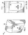
- FIG. 2 shows a preferred embodiment of supplementary lighting device 100.
- Device 100 includes a housing 202, a window 204, and a dimmer control 206.
- Dimmer control 206 allows the user to vary the pre-set intensity of illumination element 102.
- Dimmer control 206 can allow user selection in a variety of ways, as will be more fully described below.
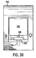
- FIG. 3A shows a front elevation view of device 100, showing housing 202, window 204, and dimmer control 206.
- Light sensor 104 is also shown in phantom.
- FIG. 3B shows a front elevation of device 100 with window 204 removed. It can be seen that illumination element 102 is located behind window 204. Light sensor 104 can also been seen in FIG. 3B. Further, aperture 302 is located near light sensor 104 to allow detection of ambient light 108.
- Illumination element 102 includes a substantially planar illumination area 402 and an elongated connection tail 404 extending from illumination area 402 .
- Conductor strips 406 are disposed on connection tail 404. Conductor strips 406 connect to control system 106 to provide power to illumination element 102, as will be explained in more detail below.
- FIG. 5 shows a side cross-section view of device 100, taken along line 5-5 of FIG. 3A.
- housing 202 and window 204 serve as an enclosure for device 100.
- Window 204 is preferably coupled to housing 202 by a fastener 502 located at a rear surface 504 of housing 202.
- Fastener 502 can be a screw or other similar type of fastening device.
- Window 204 may also be press fit into housing 202.
- a fastener is a preferred attachment device.
- the fastener be located at rear surface 504 of housing 202, because it requires removal of device 100 from the power source (wall socket) before window 204 can be removed. This safety precaution prevents one from attempting to replace illumination element 102 while device 100 is connected to the power source.
- Window 204 preferably press fits illumination area 402 of illumination element 102 against a flat interior cavity 503 of housing 202.
- Elongated tail 404 of illumination element 102 fits into a guide-way 505.
- Guide-way 505 leads to connector 506 which connects to control system 106.
- conductor strips 406 make contact with connector 506, such that control system 106 provides power to illumination element 102.
- Guide-way 505 is the only path from the user-accessible area behind window 204 to control system 106.
- Device 100 is normally plugged into a common household wall socket via electrical contact blades 508 which protrude from rear surface 504 of housing 202.
- a recess or cavity 510 is formed in rear surface 504 of housing 202 surrounding electrical contact blades 508.
- a protector 512 is disposed in cavity 510 and extends the length of blades 508.
- Protector 512 is collapsible such that it collapses into cavity 510 as blades 508 are inserted into the wall socket.
- protector 512 When blades 508 are removed from the wall socket, protector 512 extends from cavity 510 to prevent contact with blades 508 until device 100 is completely removed from the wall socket. Protector 512 therefore prevents fingers, screwdrivers, toys, etc., from contacting blades 508 while blades are still in contact with the electrical power source.
- Protector 512 is preferably made of nonconductive and resilient material such as rubber, and is preferably constructed in the form of bellows, as shown, for easy expansion and contraction.
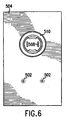
- FIG. 6 shows an elevation view ofrear surface 504 of device 100, including cavity 510, electrical connection blades 508, and fasteners 502.
- FIG. 7 shows a side elevation of device 100 coupled to a standard household outlet 702 as a power source.
- Dimmer 110 can vary the illumination intensity of illumination element 102 by directly acting with control system 106, as shown in Figure 1.
- dimmer 110 works in conjunction with light sensor 104 to mechanically and/or optically adjust the intensity of light output from illumination element 102 which is detected by light sensor 104.
- the intensity of light outputted from illumination element 102 is increased or decreased by control system 106 depending on the amount of light detected from light sensor 104. Therefore, dimmer 110 is constructed such that the amount of light detected by light sensor 104 can be artificially adjusted by the user.
- dimmer 110 comprises dimmer control 206 constructed as a small wheel which can be adjusted by the user.
- Light sensor 104 is disposed within wheel dimmer control 206 such that when dimmer control 206 is moved, light sensor 104 is angled towards or away from illumination element 102.
- light sensor 104 is angled away from illumination element 102, as shown in Fig. 8B, it detects less light from illumination element 102, thereby causing control system 106 to increase power to illumination element 102, to make increase the intensity of illumination element 102 until the system regulates itself.
- dimmer control 206 is moved in the other direction, as shown in FIG.
- light sensor 104 is angled towards illumination element 102, thereby detecting more light from illumination element 102. Consequently, control system 106 reduces power to illumination element 102 which dims the output. It would be apparent to one skilled in the relevant art from this description that light sensor 104 also moves slightly closerto and away from illumination element 102 when dimmer control 206 is moved. This further increases or decreases the amount of light detected by light sensor 104. It can further be appreciated that if light sensor 104 is moved away from the center of dimmer control 206, turning dimmer control 206 towards or away from illumination element 102 has a greater effect on the distance that light sensor 104 moves towards or away from illumination element 102.
- dimmer 110 comprises dimmer control 206 and a mechanical dimmer element constructed as a sloped section 904.
- Dimmer control 206 allows the user to slide sloped section 904 such that light sensor is progressively unblocked (FIG. 9A), partially blocked (FIG. 9B), or completely blocked (FIG. 9C).
- the amount of sloped section 904 blocking light sensor 104 adjusts the quantity of light detected by light sensor 104. Therefore, if dimmer control 206 is moved such that sloped section 904 completely blocks light sensor 104, light sensor 104 detects no light from illumination element 102, thereby causing control system 106 to increase power to illumination element 102 .
- control system 106 decreases power to illumination element 102, thereby decreasing the intensity of light emitted from illumination element 102.
- FIGs. 10A and 10B show another alternative embodiment of dimmer 110.
- dimmer 110 comprise a dimmer control 206 and a partially mirrored reflective section 1002.
- Reflective section 1002 has a sloped reflective surface across its face.
- Dimmer control 206 allows the user to slide reflective section 1002 such that light emitted from illumination element 102 is variably reflected as a function of the amount of reflective material on the part of reflective section 1002 which is positioned so as to conduct light to light sensor 104 via aperture 1004. The sliding position of dimmer control 206 therefore adjusts the quantity of light detected by light sensor 104.
- dimmer control 206 if dimmer control 206 is moved such that reflective section 1002 reflects effectively no illumination from illumination element 102, light sensor 104 detects no light from illumination element 102, thereby causing control system 106 to increase power to illumination element 102. Similarly, as dimmer control 206 is moved such that reflective section 1002 reflects a greater amount oflight from illumination element 102, light sensor 104 detects more light from illumination element 102. This causes control system 106 to decrease power to illumination element 102, thereby decreasing the intensity of light emitted from illumination element 102.
- dimmer control 206 could be coupled to illumination element 102 such that moving dimmer control 206 moves illumination element 102 towards or away from light sensor 104. This has the same effect as moving light sensor 104 towards or away from illumination element 102, as described above with respect to FIGs. 8A and 8B.
- an adjustable reflecting device could be positioned between illumination source 102 and light sensor 104. Dimmer control 206 adjusts the angle or position of the reflecting device such that light sensor 104 detects more or less light from illumination element 102.
- Several other similar devices could be designed that increase or decrease the amount of light detected by light sensor 104 from illumination element 102.
- dimmer 110 can be designed to completely shut off light from illumination source 102 to light detector 104, as discussed above. This would allow maximum light output from illumination source 102, and also provides for the greatest amount of variability in output power (i.e., from 0% to 100%). It is also possible to design dimmer 110 such that it cannot completely prevent light from illumination source 102 from reaching light detector 104. In this embodiment, the system could not produce maximum output of the illumination source, however, it could provide automatic decay adjustment over a longer period of the illumination element's life span. For example, the system could be designed such that when dimmer 110 is adjusted for maximum output, control system 106 would only provide 30% of its maximum power supplying capability to illumination element 102.
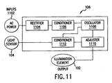
- Control system 106 receives input from AC power source 1102 and from light sensor 104. AC power is then treated through a rectifier 1104 and a power conditioner 1106. Rectifier 1104 can be a full wave rectifier, a half wave rectifier, a voltage doubler, or several other common design alternatives. Power conditioner 1106 can be comprised of capacitors, or resistors and capacitors, or inductors and capacitors, or various other common implementations. The purpose of power conditioner 1106 is to provide some amount of stabilization for the rectified power source.
- An oscillator 1108 receives the rectified and conditioned A/C power.
- Oscillator 1108 can generate a sinusoidal wave via an RC shift network, a Wien bridge, or an inductor-capacitor arrangement.
- oscillator 1108 can could generate a modified square wave or a composite wave-form via flip-flops, or an astable network, or via a free-running multi-vibrator, or via several other common circuit implementations, as would be apparent to one of ordinary skill in the relevant art.
- Oscillator 1108 could also use crystal or ceramic oscillators, or even the output of a microprocessor.
- Oscillator 1108 can be designed as either a fixed- or variable-controlled oscillator. If the design is a variable-controlled oscillator, then the conditioned signal from light sensor 104 can vary the rate of oscillation as a function of the amount of light sensed, and thus it would affect the intensity of the EL element.
- the output of the oscillator 1108 is then sent to a power adjuster 1110 which conditions the output so that it is within the operating norms of illumination element 102.
- the resulting power is then output from control system 106 and applied to the contacts of the EL lighting element, producing an appropriate glow.
- Power adjuster 1110 can be either a fixed- or variable-controlled regulator design, configured so as to adjust either the voltage or the current (or both). If the design is a variable-controlled regulator, then the conditioned signal from light sensor 104 varies the amount of power output during each oscillation as a function of the amount of light sensed, and thus it would affect the intensity of illumination element 102.
- the second input into control system 106 is from light sensor 104.
- the input from light sensor 104 is conditioned by conditioner 1112 to adjust it to the needs of the other circuitry in control system 106.
- the output from conditioner 1112 is then applied as a controlling signal for either oscillator 1108 or power adjuster 1110, or both.
- the signal from light sensor 104 affects the intensity of illumination element 102.
- the changed intensity from illumination element 102 is detected by light sensor 104 transferred to control system 106, as described above.
- This allows for constant adjustment of the intensity of illumination element 102 to a desired setting, even when illumination element 102 begins to fade.
- light sensor 104 will detect less light from illumination element 102, and power adjuster 1110 or oscillator 1108 of control system 106 will thereby increase the intensity of illumination element 102 until it reaches the intensity pre-set by the user using dimmer control 206.
- dimmer control 206 is adjusted, light sensor 104 detects less or more light from illumination element 102.
- Control system 106 automatically adjusts for this change, and power adjuster 1110 provides more or less power to illumination element 102. This allows for user control of the intensity of illumination element 102 simply by adjusting dimmer control 206.
- control system 106 can be designed such that the amount of ambient light 108 detected by light sensor 104 will be sufficient to completely shut off illumination element 102 in daylight type conditions. This provides a "daytime off' feature which extends the serviceable life of illumination element 102.
- light sensor 104 can be designed such that it receives both ambient light and light emitted from illumination element 102. Control system 106 can be designed such that the amount of ambient light 108 detected by light sensor 104 exceeds the amount of light detected from illumination element 102.
- dimmer 110 can be designed to affect only that amount of light detected by light sensor 104 which is emitted by illumination element 102. This combination of design element allows the anti-ageing feature, the daytime-off feature, and the adjustable dimmer feature to be efficiently incorporated into a supplementary lighting device.
Landscapes
- Physics & Mathematics (AREA)
- Engineering & Computer Science (AREA)
- Microelectronics & Electronic Packaging (AREA)
- Optics & Photonics (AREA)
- Circuit Arrangement For Electric Light Sources In General (AREA)
- Electroluminescent Light Sources (AREA)
Priority Applications (1)
| Application Number | Priority Date | Filing Date | Title |
|---|---|---|---|
| EP05013718A EP1587346A3 (en) | 2000-10-10 | 2000-10-10 | Electrical device with connector protection |
Applications Claiming Priority (1)
| Application Number | Priority Date | Filing Date | Title |
|---|---|---|---|
| PCT/IB2000/001543 WO2001082656A1 (en) | 2000-10-10 | 2000-10-10 | Electroluminescent lighting device |
Related Child Applications (2)
| Application Number | Title | Priority Date | Filing Date |
|---|---|---|---|
| EP05013718A Division EP1587346A3 (en) | 2000-10-10 | 2000-10-10 | Electrical device with connector protection |
| EP05013718.1 Division-Into | 2005-06-24 |
Publications (2)
| Publication Number | Publication Date |
|---|---|
| EP1325670A1 EP1325670A1 (en) | 2003-07-09 |
| EP1325670B1 true EP1325670B1 (en) | 2005-09-21 |
Family
ID=11003991
Family Applications (1)
| Application Number | Title | Priority Date | Filing Date |
|---|---|---|---|
| EP00969732A Expired - Lifetime EP1325670B1 (en) | 2000-10-10 | 2000-10-10 | Electroluminescent lighting device |
Country Status (5)
| Country | Link |
|---|---|
| EP (1) | EP1325670B1 (enExample) |
| JP (1) | JP2003532978A (enExample) |
| AT (1) | ATE305210T1 (enExample) |
| DE (1) | DE60022793D1 (enExample) |
| WO (1) | WO2001082656A1 (enExample) |
Families Citing this family (3)
| Publication number | Priority date | Publication date | Assignee | Title |
|---|---|---|---|---|
| DE102004018912A1 (de) | 2004-04-15 | 2005-11-03 | Patent-Treuhand-Gesellschaft für elektrische Glühlampen mbH | Vorrichtung zur Lichtregelung |
| ES2302432B1 (es) * | 2006-06-09 | 2009-05-08 | Mecel, S.L. | Sistema integrado de gestion de instalaciones electricas. |
| GB2469821B (en) * | 2009-04-28 | 2011-08-10 | Alistair Macfarlane | Improved light source |
Family Cites Families (7)
| Publication number | Priority date | Publication date | Assignee | Title |
|---|---|---|---|---|
| US4593234A (en) * | 1982-05-11 | 1986-06-03 | Yang Jerry S C | Programmable apparatus for controlling illuminating lamps |
| US5148014A (en) * | 1990-08-10 | 1992-09-15 | Donnelly Corporation | Mirror system with remotely actuated continuously variable reflectant mirrors |
| US5361017A (en) * | 1993-02-01 | 1994-11-01 | Astronics Corporation | Instrument panel and EL lamp thereof |
| US5537003A (en) * | 1994-04-08 | 1996-07-16 | Gentex Corporation | Control system for automotive vehicle headlamps and other vehicle equipment |
| US5670776A (en) * | 1995-01-06 | 1997-09-23 | Rothbaum; Wayne P. | Electroluminescent wall plate and switch |
| US6124672A (en) * | 1995-03-30 | 2000-09-26 | Dynamic Brilliance Corporation | Electroluminescent device with a secure contact |
| WO1999040559A2 (en) * | 1998-02-06 | 1999-08-12 | Koninklijke Philips Electronics N.V. | Organic electroluminescent device |
-
2000
- 2000-10-10 EP EP00969732A patent/EP1325670B1/en not_active Expired - Lifetime
- 2000-10-10 AT AT00969732T patent/ATE305210T1/de not_active IP Right Cessation
- 2000-10-10 JP JP2001578156A patent/JP2003532978A/ja not_active Withdrawn
- 2000-10-10 WO PCT/IB2000/001543 patent/WO2001082656A1/en not_active Ceased
- 2000-10-10 DE DE60022793T patent/DE60022793D1/de not_active Expired - Fee Related
Also Published As
| Publication number | Publication date |
|---|---|
| JP2003532978A (ja) | 2003-11-05 |
| WO2001082656A1 (en) | 2001-11-01 |
| EP1325670A1 (en) | 2003-07-09 |
| DE60022793D1 (de) | 2006-02-02 |
| ATE305210T1 (de) | 2005-10-15 |
Similar Documents
| Publication | Publication Date | Title |
|---|---|---|
| US6337541B1 (en) | Electroluminescent lighting device | |
| US5581158A (en) | Lamp brightness control circuit with ambient light compensation | |
| CA2102679C (en) | Touch dimmer system | |
| US5621283A (en) | Microprocessor based touch dimmer system to control the brightness of one or more electric lamps using single or multi-key devices | |
| CN101884251A (zh) | 用于螺纹紧凑荧光灯的两线调光器电路 | |
| US20100207532A1 (en) | Lighting controller | |
| US9141101B2 (en) | Wireless battery-powered remote control with glow-in-the-dark feature | |
| EP1404163B1 (en) | High-intensity discharge lamp ballast with live relamping feature | |
| US4985661A (en) | Uninterrupted desk lamp | |
| JP7220396B2 (ja) | 親子照明装置、親子照明装置の制御方法およびスマート照明システム | |
| WO1996017282A1 (en) | Ballast circuit for powering gas discharge lamp | |
| EP1325670B1 (en) | Electroluminescent lighting device | |
| AU2005255448B2 (en) | Appliance convenience light | |
| EP0053896A1 (en) | Light dimmer device | |
| EP1587346A2 (en) | Electrical device with connector protection | |
| US20020153780A1 (en) | Touch operated control system for electrical devices | |
| JP4048585B2 (ja) | ランプ調光点灯装置、ランプ調光方式および照明器具 | |
| US10455674B2 (en) | Methods and systems for controlling an electrical load | |
| GB2319406A (en) | Dimming a medium pressure arc lamp; UV lamp standby mode | |
| KR102815344B1 (ko) | Dc 디밍 제어가 가능한 조광기 시스템 | |
| KR200183646Y1 (ko) | 형광등용 전자식 점등관 | |
| KR930008057Y1 (ko) | 가스레인지 그릴의 점화확인장치 | |
| JP3380154B2 (ja) | 蛍光灯調光装置 | |
| JP3315398B2 (ja) | 放電ランプ点灯装置 | |
| JPH07130486A (ja) | 放電灯点灯装置 |
Legal Events
| Date | Code | Title | Description |
|---|---|---|---|
| PUAI | Public reference made under article 153(3) epc to a published international application that has entered the european phase |
Free format text: ORIGINAL CODE: 0009012 |
|
| 17P | Request for examination filed |
Effective date: 20020508 |
|
| AK | Designated contracting states |
Designated state(s): AT BE CH CY DE DK ES FI FR GB GR IE IT LI LU MC NL PT SE |
|
| AX | Request for extension of the european patent |
Extension state: AL LT LV MK RO SI |
|
| 17Q | First examination report despatched |
Effective date: 20040625 |
|
| GRAP | Despatch of communication of intention to grant a patent |
Free format text: ORIGINAL CODE: EPIDOSNIGR1 |
|
| GRAS | Grant fee paid |
Free format text: ORIGINAL CODE: EPIDOSNIGR3 |
|
| GRAA | (expected) grant |
Free format text: ORIGINAL CODE: 0009210 |
|
| AK | Designated contracting states |
Kind code of ref document: B1 Designated state(s): AT BE CH CY DE DK ES FI FR GB GR IE IT LI LU MC NL PT SE |
|
| PG25 | Lapsed in a contracting state [announced via postgrant information from national office to epo] |
Ref country code: IT Free format text: LAPSE BECAUSE OF FAILURE TO SUBMIT A TRANSLATION OF THE DESCRIPTION OR TO PAY THE FEE WITHIN THE PRESCRIBED TIME-LIMIT;WARNING: LAPSES OF ITALIAN PATENTS WITH EFFECTIVE DATE BEFORE 2007 MAY HAVE OCCURRED AT ANY TIME BEFORE 2007. THE CORRECT EFFECTIVE DATE MAY BE DIFFERENT FROM THE ONE RECORDED. Effective date: 20050921 Ref country code: FI Free format text: LAPSE BECAUSE OF FAILURE TO SUBMIT A TRANSLATION OF THE DESCRIPTION OR TO PAY THE FEE WITHIN THE PRESCRIBED TIME-LIMIT Effective date: 20050921 Ref country code: AT Free format text: LAPSE BECAUSE OF FAILURE TO SUBMIT A TRANSLATION OF THE DESCRIPTION OR TO PAY THE FEE WITHIN THE PRESCRIBED TIME-LIMIT Effective date: 20050921 Ref country code: LI Free format text: LAPSE BECAUSE OF FAILURE TO SUBMIT A TRANSLATION OF THE DESCRIPTION OR TO PAY THE FEE WITHIN THE PRESCRIBED TIME-LIMIT Effective date: 20050921 Ref country code: NL Free format text: LAPSE BECAUSE OF FAILURE TO SUBMIT A TRANSLATION OF THE DESCRIPTION OR TO PAY THE FEE WITHIN THE PRESCRIBED TIME-LIMIT Effective date: 20050921 Ref country code: CH Free format text: LAPSE BECAUSE OF FAILURE TO SUBMIT A TRANSLATION OF THE DESCRIPTION OR TO PAY THE FEE WITHIN THE PRESCRIBED TIME-LIMIT Effective date: 20050921 Ref country code: BE Free format text: LAPSE BECAUSE OF FAILURE TO SUBMIT A TRANSLATION OF THE DESCRIPTION OR TO PAY THE FEE WITHIN THE PRESCRIBED TIME-LIMIT Effective date: 20050921 |
|
| REG | Reference to a national code |
Ref country code: GB Ref legal event code: FG4D |
|
| REG | Reference to a national code |
Ref country code: CH Ref legal event code: EP |
|
| PG25 | Lapsed in a contracting state [announced via postgrant information from national office to epo] |
Ref country code: CY Free format text: LAPSE BECAUSE OF FAILURE TO SUBMIT A TRANSLATION OF THE DESCRIPTION OR TO PAY THE FEE WITHIN THE PRESCRIBED TIME-LIMIT Effective date: 20051010 Ref country code: IE Free format text: LAPSE BECAUSE OF NON-PAYMENT OF DUE FEES Effective date: 20051010 |
|
| REG | Reference to a national code |
Ref country code: IE Ref legal event code: FG4D |
|
| REF | Corresponds to: |
Ref document number: 60022793 Country of ref document: DE Date of ref document: 20051027 Kind code of ref document: P |
|
| PG25 | Lapsed in a contracting state [announced via postgrant information from national office to epo] |
Ref country code: MC Free format text: LAPSE BECAUSE OF NON-PAYMENT OF DUE FEES Effective date: 20051031 |
|
| PG25 | Lapsed in a contracting state [announced via postgrant information from national office to epo] |
Ref country code: LU Free format text: LAPSE BECAUSE OF NON-PAYMENT OF DUE FEES Effective date: 20051121 |
|
| PG25 | Lapsed in a contracting state [announced via postgrant information from national office to epo] |
Ref country code: SE Free format text: LAPSE BECAUSE OF FAILURE TO SUBMIT A TRANSLATION OF THE DESCRIPTION OR TO PAY THE FEE WITHIN THE PRESCRIBED TIME-LIMIT Effective date: 20051221 Ref country code: DK Free format text: LAPSE BECAUSE OF FAILURE TO SUBMIT A TRANSLATION OF THE DESCRIPTION OR TO PAY THE FEE WITHIN THE PRESCRIBED TIME-LIMIT Effective date: 20051221 Ref country code: GR Free format text: LAPSE BECAUSE OF FAILURE TO SUBMIT A TRANSLATION OF THE DESCRIPTION OR TO PAY THE FEE WITHIN THE PRESCRIBED TIME-LIMIT Effective date: 20051221 Ref country code: GB Free format text: LAPSE BECAUSE OF NON-PAYMENT OF DUE FEES Effective date: 20051221 |
|
| PG25 | Lapsed in a contracting state [announced via postgrant information from national office to epo] |
Ref country code: ES Free format text: LAPSE BECAUSE OF FAILURE TO SUBMIT A TRANSLATION OF THE DESCRIPTION OR TO PAY THE FEE WITHIN THE PRESCRIBED TIME-LIMIT Effective date: 20060101 |
|
| REF | Corresponds to: |
Ref document number: 60022793 Country of ref document: DE Date of ref document: 20060202 Kind code of ref document: P |
|
| PG25 | Lapsed in a contracting state [announced via postgrant information from national office to epo] |
Ref country code: PT Free format text: LAPSE BECAUSE OF FAILURE TO SUBMIT A TRANSLATION OF THE DESCRIPTION OR TO PAY THE FEE WITHIN THE PRESCRIBED TIME-LIMIT Effective date: 20060221 |
|
| NLV1 | Nl: lapsed or annulled due to failure to fulfill the requirements of art. 29p and 29m of the patents act | ||
| REG | Reference to a national code |
Ref country code: CH Ref legal event code: PL |
|
| PG25 | Lapsed in a contracting state [announced via postgrant information from national office to epo] |
Ref country code: DE Free format text: LAPSE BECAUSE OF NON-PAYMENT OF DUE FEES Effective date: 20060503 |
|
| PLBE | No opposition filed within time limit |
Free format text: ORIGINAL CODE: 0009261 |
|
| STAA | Information on the status of an ep patent application or granted ep patent |
Free format text: STATUS: NO OPPOSITION FILED WITHIN TIME LIMIT |
|
| REG | Reference to a national code |
Ref country code: IE Ref legal event code: MM4A |
|
| GBPC | Gb: european patent ceased through non-payment of renewal fee |
Effective date: 20051221 |
|
| 26N | No opposition filed |
Effective date: 20060622 |
|
| PG25 | Lapsed in a contracting state [announced via postgrant information from national office to epo] |
Ref country code: FR Free format text: LAPSE BECAUSE OF FAILURE TO SUBMIT A TRANSLATION OF THE DESCRIPTION OR TO PAY THE FEE WITHIN THE PRESCRIBED TIME-LIMIT Effective date: 20061020 |
|
| EN | Fr: translation not filed | ||
| PG25 | Lapsed in a contracting state [announced via postgrant information from national office to epo] |
Ref country code: FR Free format text: LAPSE BECAUSE OF FAILURE TO SUBMIT A TRANSLATION OF THE DESCRIPTION OR TO PAY THE FEE WITHIN THE PRESCRIBED TIME-LIMIT Effective date: 20051031 |
|
| PG25 | Lapsed in a contracting state [announced via postgrant information from national office to epo] |
Ref country code: FR Free format text: LAPSE BECAUSE OF FAILURE TO SUBMIT A TRANSLATION OF THE DESCRIPTION OR TO PAY THE FEE WITHIN THE PRESCRIBED TIME-LIMIT Effective date: 20050921 |