EP1324289A2 - Method and apparatus for performing procedures - Google Patents
Method and apparatus for performing procedures Download PDFInfo
- Publication number
- EP1324289A2 EP1324289A2 EP02258847A EP02258847A EP1324289A2 EP 1324289 A2 EP1324289 A2 EP 1324289A2 EP 02258847 A EP02258847 A EP 02258847A EP 02258847 A EP02258847 A EP 02258847A EP 1324289 A2 EP1324289 A2 EP 1324289A2
- Authority
- EP
- European Patent Office
- Prior art keywords
- sensor
- human interpretable
- parameter
- indicator
- human
- Prior art date
- Legal status (The legal status is an assumption and is not a legal conclusion. Google has not performed a legal analysis and makes no representation as to the accuracy of the status listed.)
- Granted
Links
Images




Classifications
-
- B—PERFORMING OPERATIONS; TRANSPORTING
- B65—CONVEYING; PACKING; STORING; HANDLING THIN OR FILAMENTARY MATERIAL
- B65H—HANDLING THIN OR FILAMENTARY MATERIAL, e.g. SHEETS, WEBS, CABLES
- B65H43/00—Use of control, checking, or safety devices, e.g. automatic devices comprising an element for sensing a variable
-
- B—PERFORMING OPERATIONS; TRANSPORTING
- B65—CONVEYING; PACKING; STORING; HANDLING THIN OR FILAMENTARY MATERIAL
- B65H—HANDLING THIN OR FILAMENTARY MATERIAL, e.g. SHEETS, WEBS, CABLES
- B65H2551/00—Means for control to be used by operator; User interfaces
- B65H2551/20—Display means; Information output means
-
- B—PERFORMING OPERATIONS; TRANSPORTING
- B65—CONVEYING; PACKING; STORING; HANDLING THIN OR FILAMENTARY MATERIAL
- B65H—HANDLING THIN OR FILAMENTARY MATERIAL, e.g. SHEETS, WEBS, CABLES
- B65H2601/00—Problem to be solved or advantage achieved
- B65H2601/10—Ensuring correct operation
- B65H2601/11—Clearing faulty handling, e.g. jams
Definitions
- the present invention relates to the field of maintenance and repair sequences for complicated equipment. More particularly, the present invention relates to apparatus and method for guiding human operators through a sequence of tasks such as removing of paper jams in complex production reprographic equipment. While this invention will be illustrated in relation to the task of removing such paper jams, it is believed that the apparatus and methods of the present invention have wide applicability, particularly to routine maintenance or repair operations to be performed by human operators that have not been specially trained and for such operations when many variables combine to vary the sequence from one operation to the next.
- the UI instructs (user interface) the operator in the case of a jam which cabinet doors must be opened and/or components like finishers must be separated.
- an apparatus having procedures to be performed and having parameters indicating apparatus status including fault parameters and nominal parameters comprises:
- a process for guiding human operator procedures for an apparatus having parameters indicating system status including fault parameters and nominal parameters comprises:
- Such an automatic guide system preferably allows an operator to remain in situ at the place of repair, maintenance or reassembly without needing to physically move or to change the focus of his/her attention.
- repair, maintenance, and assembly/reassembly processes become more efficient and more reliable with decreased risk that an improper sequence will damage components, and require less training for human operators.
- the present invention not only may be adapted to guide the sequence of operations but may, in addition, be adapted to direct movements or other manipulation of levers, latches, pulls, knobs, drawers, etc.
- FIG. 1-4 a sequence for clearing an exemplary paper jam in an electrophotographic printing machine is shown. Not all paper jams will occur in the same locations or require the same sequence even for the same machine.
- sensors within the machine have detected a misfeed from copy sheet feeder apparatus (not shown).
- the machine has halted operation and informed the operator that a jam has occurred.
- the UI user interface
- the controller and sensors have cooperated to determine which sheets undergoing processing can be processed through to completion and which must be halted along the sheet path.
- Figure 1 shows an embodiment of the present invention where the operator opens the cabinet doors 20 and 21 of printer 30 and immediately sees an illuminated handle, lever, or other disassembly fixture 15.
- illumination 15 may be by a switched incandescent or fluorescent light bulb or, preferably, illumination by such means as LEDs embedded into the disassembly fixture itself. It is possible that indicators other than illumination will work, such as sound or blinking lights, but the invention will be explained using illumination as the user indicator.
- Such illumination immediately draws the operator's attention to disassembly fixture 15 and informs the operator which step is to be performed first. He does not need to guess which procedure to implement first nor which disassembly fixture will implement the chosen disassembly procedure.
- the illumination at fixture 15 ceases and, as shown in Figure 2, an other illumination draws the operators attention to fixture 16.
- illumination of fixture 15 will not cease and illumination at fixture 16 will not commence until the work at fixture 15 is correctly completed.
- fixture 15 remains illuminated even after the operator returns any moved parts back to their operational position. Equally important, if some component had been moved during the operation at fixture 15 but had not been returned to its proper position, then fixture 15 would remain illuminated, and the operator would know that something needed correction.
- the present invention provides the operator confidence that procedures at fixture 15 have been completed successfully. By illumination at fixture 16, the operator need not guess which operation to perform next or which fixture to manipulate in order to perform the procedure.
- FIG 3 the operator observes that fixture 16 is no longer illuminated, and his attention is immediately drawn to the newly illuminated fixture 17.
- this switch in illumination conveys valuable information, including that the preceding operation was completely thoroughly and correctly.
- the operator Upon completing the operation at fixture 17, the operator will observe that illumination has moved to cabinet doors 20 and 21.
- illumination at the cabinet doors informs the operator that the repair has been completed. In this case, illumination of the doors indicates that the sheets jammed in the printer have all been removed.
- any type of overall completion indicator could be employed, including sound emitters or lights at a different location than the cabinet doors.
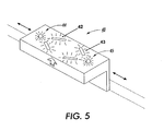
- handle 40 is a grip handle to enable an operator to slide a portion of a subassembly in the direction of arrow 41 in order to obtain access to a jammed sheet.
- handle 40 has two sets of illuminators. LEDs 44 and 45 are colored red and green, respectively. As long as the controller senses a sheet at the location of handle 40, the red light 44 remains lit. The operator knows that all sheets accessible by handle 40 have been removed when the red LED 44 is dimmed and the green light 45 is lit.
- This variation on the present invention provides the operator with even more information since he does not need to return handle 40 to its operating position without knowing with certainty that all sheets have been removed that should be removed. Without this feature, the operator will not progress to the next station under the present invention but he may open and close handle 40 multiple times until the LEDs on handle 40 are extinguished and the next set of illuminators light up.
- a second feature revealed in Figure 5 is a directional signal 42, 43 formed by LED lights. These indicate to an operator which direction the handle is to be moved for the correct operation. For untrained operators dealing with complex machines, indicators that direct movement in one direction for opening and the opposite for closing greatly simply instructions and provide more certainty. As shown in Figure 5, direction can be indicated by a pattern of lights. Alternatively, LEDs could blink in a sequence that the human eye perceives to be leading in one direction or the other.
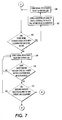
- a jam has occurred.
- the controller enters into its fault detection subroutines, which in this case deduces that the first subassembly within the system to seize or otherwise indicate a jam must be the location where the first jam occurs.
- the controller signals a halt to operations that involve sheets preceding the jammed subassembly in the sheet path. Operations involving sheets in front of the jam are allowed to proceed. This feature is taught and more fully set forth in US-A-4627711 and US-A-4497569.
- the controller interrogates sensors determine the locations of sheets remaining after the unjammed sheet processing has continued.
- the controller determines which location is to be cleared next. This sheet location is selected for clearance first.
- the controller determines which disassembly fixtures are associated with the selected Sheet location.
- the controller typically refers to a look-up table to determine whether the selected sheet location requires one or a plurality of disassembly operations to obtain access to the selected sheet. If yes, then at 107 the controller again refers to a look-up table or algorithm to determine which of the several disassembly fixtures should be selected for the initial disassembly operation for that sheet location.
- step 107 once the controller has selected the appropriate disassembly fixture, then, at 108, a signal is sent to activate the LEDs associated with such fixture. Since there are multiple fixtures associated with this sheet location, the algorithm returns to step 106 where the loop 106-108 is repeated until all disassembly operations at the selected sheet location are completed. When all but the last such disassembly operation at that sheet location is completed, then the controller algorithm proceeds to step 109 where a signal is sent to the last fixture at that location for the LEDs to light.
- signals for steps 108, 109, or other steps can be sent in any number of ways. Sensors and LEDs can obviously be wired for conventional electrical signals. Another embodiment is to minimize wiring within the system by sending such signals through Radio Frequency (RF) transmitters and receivers.
- RF Radio Frequency
- Such RF technology is now relatively inexpensive and readily available on EEPROMs and similar semiconductor chips.
- One additional advantage of using RF signals is that machines produced or initially designed without the present invention can be retrofitted without introducing a major new set of wires. All that is required is a means for supplying power to LEDs, and such power can be tapped from wires carrying power near the LED sites or may even be supplied by batteries that would need to be replaced periodically.
- step 110 the controller interrogates the sheet sensors whether all sheets at this location have been removed. As described above, this step is a major advantage of the present invention since under the prior art, the operator may not realize that multiple sheets at this location are to be removed. The operator may thus remove one sheet and proceed to reassemble the entire machine only to find later that additional sheets are still buried somewhere in the apparatus.
- the inquiry of step 110 may be sequenced on a timed manner, e.g., every 2 seconds, or may be triggered by some other event such as a change in signals sent from the sheet sensors. If the answer to the inquiry in 110 is negative, then the controller returns to step 109, and the iteration between 110 and 109 continues until all sheet sensors at this location indicate sheet clearance.
- an additional embodiment of the present invention is to have two separate LED indicators at each disassembly fixture. When all sheet sensors indicate clearance, then the LEDs switch from red to green, for example, so that the operator knows that all sheets are cleared and he may proceed to the next step.
- step 110 enables the controller to proceed to step 111.
- reassembly at the sheet location occurs as soon as sheets at that location have been cleared. It is also possible for some maintenance and repair operations that reassembly would not occur until later in the process, and step 111 may be moved to a later stage of the process.
- the controller interrogates sensors, that may be electrical contacts in latches, pressure sensors, etc, whether the reassembly at the selected sheet location has been completed. If not, then the operator continues to see that he has work to perform at that location since the controller returns to step 109 until it receives confirmation of successful reassembly.
- step 111 the controller senses that step 111 is complete, then the applicable LEDs that location dim and the controller proceeds to step 112.
- step 112. the controller again interrogates the various sheet sensors to determine if additional sheets must be removed. If sensors in other locations indicate such a presence of additional sheets (which is the normal occurrence for most sheet jams), then the controller returns to step 103 and the process will be repeated.
- the great advantage is that a new set of LEDs light up another disassembly fixture, and the operator need not stand up to look at the UI nor wonder which step he should perform next.
- the controller in effect, has removed doubt and made informed decisions for the operator.
- the operator need not perform unnecessary relating to sheets that were not jammed and were, instead, processed to completion. This ability to save operator disassembly steps saves time, effort, and minimized the wear and tear on machine components since fewer will be jostled, moved, etc.
- step 112 the controller completes step 112 and confirms that all sheets have been removed, it proceeds to step 113 where it seeks to reconfirm that all reassembly operations have been performed correctly. If a reassembly sensor indicates that a subassembly needs readjustment, etc, then the controller returns to step 111. If all reassembly sensors check out correctly, then the controller proceeds to step 114. At 114, the LEDs associated with the cabinet doors light. This is the signal to the operator that the sheet jam process has essentially been completed. Again, the operator is saved from needing to change posture to look at the UI and is also saved from believing that he has completed the process only to find when he again stands to operate the machine that the doors must be opened again and some operation must be repeated.
- the controller inquiries whether the doors have been properly closed. This is similar to other reassembly steps in 111 and 113 and may rely upon electrical connections in latches, pressure sensors, etc. Once an affirmative signal has been sent, then the paper jam subroutine software in the controller is exited by the controller. The software controlling performance eof the print job is resumed, and the UI once again presents to the operator information relating to job processing rather than maintenance or repair.
- the present invention and the processes associated therewith offer great flexibility even within the same hardware system.
- different software can be accessed and different procedures can be directed by the indicators of the present invention.
- another advantage is that even the same type of operation, such as a paper jam, may favorably be directed differently depending upon the specific circumstances of each occurrence.
- the processes and apparatus of the present invention permit a wide degree of flexibility that increase efficiency, requires less training for operators, less physical effort by operators, and less wear and tear on the apparatus itself.
Landscapes
- Accessory Devices And Overall Control Thereof (AREA)
- Control Or Security For Electrophotography (AREA)
- Controlling Sheets Or Webs (AREA)
- Facsimiles In General (AREA)
Abstract
Description
Claims (8)
- An apparatus having procedures to be performed and having parameters indicating apparatus status including fault parameters and nominal parameters comprising:a. a first human interpretable indicator (15) located proximate to an apparatus site where a procedure is to be performed;b. a second human interpretable indicator (16) located proximate to an apparatus site where a procedure is to be performed;c. a first sensor, associated with the first human interpretable indicator (15), for sensing an apparatus status parameter at the site proximate to the first human interpretable indicator;d. a second sensor, associated with the second human interpretable indicator (16), for sensing an apparatus status parameter at the site proximate to the second human interpretable indicator; ande. a controller for determining a sequence of procedures, said controller communicating with the first and second human interpretable indicators (15, 16) and the first and second sensors wherein, in response to a signal from the first sensor that a fault parameter exists, the controller directs activation of the first human interpretable indicator and, in response to a signal from the first sensor that a nominal parameter exists, inquires of the second sensor whether a fault parameter exists and, if such fault parameter exists, directs activation of the second human interpretable indicator.
- The apparatus of claim 1, wherein the second human interpretable indicator (16) is not activated until the first sensor indicates that a nominal parameter exists and, upon such signal from the first sensor, the first human interpretable indicator (15) is inactivated.
- The apparatus of claim 1 or claim 2, wherein a transition from a fault parameter to a nominal parameter indicates that the operation at the site of the first human interpretable indicator (15) has been completed successfully.
- The apparatus of any of claims 1 to 3, further comprising a last of a series of human interpretable indicators wherein activation of said last human interpretable indicator indicates that all sensors associated with other human interpretable indicator within the series are communicating that nominal parameters are sensed.
- The apparatus of any of the preceding claims, wherein the apparatus comprises an electrophotographic reprographic system.
- The apparatus of claim 5, wherein at least one sensor senses whether a sheet is jammed within the system.
- A process for guiding human operator procedures for an apparatus having parameters indicating system status including fault parameters and nominal parameters, said process comprising:a. sensing a fault parameter by a first sensor;b. activating a first human interpretable indicator (15) proximate to the parameter site sensed by the first sensor;c. in response to sensing a nominal parameter at the first sensor, interrogating a second sensor to determine whether a fault parameter is sensed by the second sensor; andd. in response to sensing a fault parameter by the second sensor, activating a second human interpretable indicator (16) proximate to the parameter site sensed by the second sensor.
- The process of claim 7, wherein the step of activating the second human interpretable indicator (16) occurs after the first sensor indicates that a nominal parameter exists.
Applications Claiming Priority (2)
| Application Number | Priority Date | Filing Date | Title |
|---|---|---|---|
| US10/029,312 US6658218B2 (en) | 2001-12-28 | 2001-12-28 | Illuminated components for guiding maintenance and repair sequence |
| US29213 | 2001-12-28 |
Publications (3)
| Publication Number | Publication Date |
|---|---|
| EP1324289A2 true EP1324289A2 (en) | 2003-07-02 |
| EP1324289A3 EP1324289A3 (en) | 2004-11-10 |
| EP1324289B1 EP1324289B1 (en) | 2007-10-03 |
Family
ID=21848379
Family Applications (1)
| Application Number | Title | Priority Date | Filing Date |
|---|---|---|---|
| EP02258847A Expired - Lifetime EP1324289B1 (en) | 2001-12-28 | 2002-12-20 | Method and apparatus for performing procedures |
Country Status (4)
| Country | Link |
|---|---|
| US (1) | US6658218B2 (en) |
| EP (1) | EP1324289B1 (en) |
| JP (1) | JP2003263077A (en) |
| CA (1) | CA2415030C (en) |
Cited By (4)
| Publication number | Priority date | Publication date | Assignee | Title |
|---|---|---|---|---|
| EP1528786A3 (en) * | 2003-10-31 | 2005-08-24 | Xerox Corporation | Duplex input scanning for a partially disabled image scanner |
| WO2005118443A3 (en) * | 2004-06-04 | 2006-09-14 | Rue De Int Ltd | Document sorting machine |
| EP1862414A3 (en) * | 2004-06-04 | 2007-12-19 | De La Rue International Limited | Document sorting machine |
| EP3671427A1 (en) * | 2018-12-21 | 2020-06-24 | Xerox Corporation | Ambient lighting indicating machine status conditions |
Families Citing this family (30)
| Publication number | Priority date | Publication date | Assignee | Title |
|---|---|---|---|---|
| US7092646B2 (en) * | 2003-04-28 | 2006-08-15 | Hewlett-Packard Development Company, L.P. | Printing device and method for locating a media jam |
| US7127184B2 (en) * | 2003-12-05 | 2006-10-24 | Lexmark International, Inc. | Method and device for clearing media jams from an image forming device |
| JP4630783B2 (en) * | 2004-12-16 | 2011-02-09 | キヤノン株式会社 | Peripheral device control system, printing device, peripheral device control method, and program |
| KR20070095470A (en) * | 2005-07-18 | 2007-10-01 | 삼성전자주식회사 | Display method of paper error in the image forming apparatus and the image forming apparatus |
| US20070024917A1 (en) * | 2005-07-29 | 2007-02-01 | Lexmark International, Inc. | Device access area illumination in an imaging apparatus |
| CA2625348C (en) * | 2005-10-07 | 2015-03-17 | Ops Solutions Llc | Light guided assembly system |
| JP5011730B2 (en) * | 2006-01-18 | 2012-08-29 | 富士ゼロックス株式会社 | Image forming apparatus, sub-unit replacement method, and image forming apparatus maintenance method |
| US7403721B2 (en) * | 2006-02-28 | 2008-07-22 | Kabushiki Kaisha Toshiba | Image forming apparatus, MFP and method of displaying jam removal guidance |
| US20080047448A1 (en) * | 2006-08-28 | 2008-02-28 | Thomas G Cocklin | Printing device and method |
| US8108098B2 (en) * | 2007-09-12 | 2012-01-31 | International Business Machines Corporation | Control appropriateness illumination for corrective response |
| JP5424676B2 (en) * | 2009-03-13 | 2014-02-26 | キヤノン株式会社 | Image processing device |
| US8872627B2 (en) * | 2010-02-12 | 2014-10-28 | Biotillion, Llc | Tracking biological and other samples using RFID tags |
| US8801308B2 (en) | 2011-03-11 | 2014-08-12 | Xerox Corporation | Printing device internal lighting |
| US9431692B2 (en) | 2011-04-07 | 2016-08-30 | Biotillion, Llc | Tracking biological and other samples using RFID tags |
| US8626003B2 (en) * | 2011-04-26 | 2014-01-07 | Xerox Corporation | Printing device having internal graphic user interface display |
| US9486807B2 (en) * | 2013-03-15 | 2016-11-08 | ACCO Brands Corporation | Shredder with interactive interface |
| JP6264957B2 (en) * | 2013-05-07 | 2018-01-24 | 株式会社リコー | Image forming apparatus, recording medium supply apparatus, and image forming system |
| WO2015006334A1 (en) | 2013-07-08 | 2015-01-15 | Ops Solutions Llc | Eyewear operational guide system and method |
| JP6587513B2 (en) * | 2015-11-11 | 2019-10-09 | キヤノン株式会社 | Image forming apparatus |
| JP6685746B2 (en) * | 2016-02-09 | 2020-04-22 | キヤノン株式会社 | Image forming apparatus and image forming system |
| US9939762B2 (en) * | 2016-02-09 | 2018-04-10 | Canon Kabushiki Kaisha | Image forming apparatus and sheet feeding device |
| JP6849332B2 (en) * | 2016-02-09 | 2021-03-24 | キヤノン株式会社 | Image forming device and image forming system |
| US10073664B2 (en) | 2016-06-20 | 2018-09-11 | Xerox Corporation | System and method for conveying print device status information using a light indicator feedback mechanism |
| US9774749B1 (en) | 2016-06-20 | 2017-09-26 | Xerox Corporation | Multimodal dynamic power feedback mechanism for print devices |
| EP3600896B1 (en) | 2017-07-11 | 2023-03-22 | Hewlett-Packard Development Company, L.P. | Fluid ejection devices with indicators |
| JP7031163B2 (en) * | 2017-08-08 | 2022-03-08 | コニカミノルタ株式会社 | Image forming device |
| US11107236B2 (en) | 2019-04-22 | 2021-08-31 | Dag Michael Peter Hansson | Projected augmented reality interface with pose tracking for directing manual processes |
| US12006126B2 (en) | 2019-09-03 | 2024-06-11 | Bio Tillion, Llc | Techniques for tracking physical parameters such as temperature of transported biological materials |
| KR102821029B1 (en) * | 2020-06-26 | 2025-06-16 | 후지필름 가부시키가이샤 | Composition, transfer film, method for producing laminate, method for producing circuit wiring, and method for producing electronic device |
| JP7647119B2 (en) * | 2021-01-25 | 2025-03-18 | セイコーエプソン株式会社 | Image forming device |
Family Cites Families (16)
| Publication number | Priority date | Publication date | Assignee | Title |
|---|---|---|---|---|
| US4176941A (en) * | 1978-02-27 | 1979-12-04 | Van Dyk Research Corporation | Malfunction display system for electrophotographic copying machines |
| JPS5574553A (en) * | 1978-11-29 | 1980-06-05 | Sharp Corp | Copying machine |
| JPS57161865A (en) * | 1981-03-31 | 1982-10-05 | Toshiba Corp | Electronic copying machine |
| US4497569A (en) | 1982-09-21 | 1985-02-05 | Xerox Corporation | Copy processing system for a reproduction machine |
| US4682158A (en) * | 1984-03-23 | 1987-07-21 | Ricoh Company, Ltd. | Guidance device for manipulation of machine |
| JPS60262757A (en) * | 1984-06-08 | 1985-12-26 | Fuji Xerox Co Ltd | Jam detecting apparatus |
| US4627711A (en) | 1985-09-30 | 1986-12-09 | Xerox Corporation | Machine shutdown control |
| JPH0674100B2 (en) * | 1987-04-14 | 1994-09-21 | 富士写真フイルム株式会社 | Jam detection display device |
| JP2684725B2 (en) * | 1988-11-18 | 1997-12-03 | 富士ゼロックス株式会社 | Image processing device |
| JPH04148754A (en) * | 1990-10-11 | 1992-05-21 | Canon Inc | Sheet conveyance device |
| JP2904945B2 (en) * | 1991-02-19 | 1999-06-14 | キヤノン株式会社 | Image forming device |
| JPH04355774A (en) * | 1991-06-04 | 1992-12-09 | Ricoh Co Ltd | Jam processing display device |
| JPH07172625A (en) * | 1993-12-15 | 1995-07-11 | Konica Corp | Image forming device having feed failure display means |
| US5790374A (en) * | 1996-12-06 | 1998-08-04 | Ncr Corporation | Method and apparatus for providing power activity and fault light support using light conduits for single connector architecture (SCA) disk drives |
| JP2001522473A (en) * | 1997-04-30 | 2001-11-13 | オーセ プリンティング システムズ ゲゼルシャフト ミット ベシュレンクテル ハフツング | Method of operating a high-performance printing machine or copier having a support function in an error state |
| JP2001247235A (en) * | 2000-03-06 | 2001-09-11 | Ricoh Co Ltd | Image forming device |
-
2001
- 2001-12-28 US US10/029,312 patent/US6658218B2/en not_active Expired - Lifetime
-
2002
- 2002-12-20 JP JP2002369229A patent/JP2003263077A/en active Pending
- 2002-12-20 EP EP02258847A patent/EP1324289B1/en not_active Expired - Lifetime
- 2002-12-20 CA CA002415030A patent/CA2415030C/en not_active Expired - Fee Related
Cited By (4)
| Publication number | Priority date | Publication date | Assignee | Title |
|---|---|---|---|---|
| EP1528786A3 (en) * | 2003-10-31 | 2005-08-24 | Xerox Corporation | Duplex input scanning for a partially disabled image scanner |
| WO2005118443A3 (en) * | 2004-06-04 | 2006-09-14 | Rue De Int Ltd | Document sorting machine |
| EP1862414A3 (en) * | 2004-06-04 | 2007-12-19 | De La Rue International Limited | Document sorting machine |
| EP3671427A1 (en) * | 2018-12-21 | 2020-06-24 | Xerox Corporation | Ambient lighting indicating machine status conditions |
Also Published As
| Publication number | Publication date |
|---|---|
| EP1324289B1 (en) | 2007-10-03 |
| EP1324289A3 (en) | 2004-11-10 |
| CA2415030C (en) | 2007-12-18 |
| JP2003263077A (en) | 2003-09-19 |
| CA2415030A1 (en) | 2003-06-28 |
| US6658218B2 (en) | 2003-12-02 |
| US20030123886A1 (en) | 2003-07-03 |
Similar Documents
| Publication | Publication Date | Title |
|---|---|---|
| EP1324289B1 (en) | Method and apparatus for performing procedures | |
| DE60222730T2 (en) | Method and apparatus for performing tasks | |
| US5479859A (en) | Method and apparatus for controlling the automated changing of printing plates in printing machines | |
| US8613303B1 (en) | Tire changing machine with force detection and control methods | |
| EP2255932B1 (en) | Robot control system | |
| EP0783091B1 (en) | Transmission device for air conditioner | |
| US5937149A (en) | System for controlling the automated printing plate change process in printing machines | |
| US5111383A (en) | Apparatus for recovering sequentially controlled apparatus | |
| US20090234483A1 (en) | Remote Access Unit and Method for Managing Welding Devices Connected to a Network Via Interfaces | |
| US7098425B2 (en) | Universal wire feeder | |
| JP2006122703A (en) | Embroidery including stitching using computer | |
| CN105610031B (en) | Cable processing device | |
| EP1424885A2 (en) | Electronic component mounting apparatus and electronic component mounting method | |
| CN103199871A (en) | Method for controlling self-adaptive function replacement of control button | |
| US6732668B2 (en) | Light indicating in computerized stitching | |
| RU2302324C1 (en) | Control system | |
| CN104061657B (en) | Air conditioner and control method and device thereof | |
| KR101858517B1 (en) | Integrated automatic control system and method for cutting machine | |
| KR101161024B1 (en) | A cloth cutting device used in a sewing machine for looping eyelet button holes | |
| JP5062102B2 (en) | Automatic driving device | |
| US7409249B2 (en) | Error display system | |
| KR102427391B1 (en) | punching device | |
| JP6441920B2 (en) | Tape feeder | |
| US7069923B2 (en) | Apparatus and method of controlling fan motor in downdraft gas range | |
| EP3940466A3 (en) | Information processing apparatus, display control method, program, substrate processing system, and method for manufacturing article |
Legal Events
| Date | Code | Title | Description |
|---|---|---|---|
| PUAI | Public reference made under article 153(3) epc to a published international application that has entered the european phase |
Free format text: ORIGINAL CODE: 0009012 |
|
| AK | Designated contracting states |
Designated state(s): AT BE BG CH CY CZ DE DK EE ES FI FR GB GR IE IT LI LU MC NL PT SE SI SK TR |
|
| AX | Request for extension of the european patent |
Extension state: AL LT LV MK RO |
|
| RIN1 | Information on inventor provided before grant (corrected) |
Inventor name: KROLCZYK, MARC J. Inventor name: ZIELINSKI, JEFFREY M. Inventor name: SKILLERN, WILLIAM Inventor name: RIECK, KENNETH J. Inventor name: HAYWARD, KEN |
|
| PUAL | Search report despatched |
Free format text: ORIGINAL CODE: 0009013 |
|
| RIC1 | Information provided on ipc code assigned before grant |
Ipc: 7G 08B 21/00 A Ipc: 7B 65H 7/06 B Ipc: 7B 65H 43/00 B Ipc: 7G 03G 15/00 B |
|
| AK | Designated contracting states |
Kind code of ref document: A3 Designated state(s): AT BE BG CH CY CZ DE DK EE ES FI FR GB GR IE IT LI LU MC NL PT SE SI SK TR |
|
| AX | Request for extension of the european patent |
Extension state: AL LT LV MK RO |
|
| 17P | Request for examination filed |
Effective date: 20050510 |
|
| AKX | Designation fees paid |
Designated state(s): DE FR GB |
|
| 17Q | First examination report despatched |
Effective date: 20060718 |
|
| GRAP | Despatch of communication of intention to grant a patent |
Free format text: ORIGINAL CODE: EPIDOSNIGR1 |
|
| GRAS | Grant fee paid |
Free format text: ORIGINAL CODE: EPIDOSNIGR3 |
|
| GRAA | (expected) grant |
Free format text: ORIGINAL CODE: 0009210 |
|
| AK | Designated contracting states |
Kind code of ref document: B1 Designated state(s): DE FR GB |
|
| REG | Reference to a national code |
Ref country code: GB Ref legal event code: FG4D |
|
| REF | Corresponds to: |
Ref document number: 60222730 Country of ref document: DE Date of ref document: 20071115 Kind code of ref document: P |
|
| ET | Fr: translation filed | ||
| PLBE | No opposition filed within time limit |
Free format text: ORIGINAL CODE: 0009261 |
|
| STAA | Information on the status of an ep patent application or granted ep patent |
Free format text: STATUS: NO OPPOSITION FILED WITHIN TIME LIMIT |
|
| 26N | No opposition filed |
Effective date: 20080704 |
|
| REG | Reference to a national code |
Ref country code: FR Ref legal event code: PLFP Year of fee payment: 14 |
|
| REG | Reference to a national code |
Ref country code: FR Ref legal event code: PLFP Year of fee payment: 15 |
|
| PGFP | Annual fee paid to national office [announced via postgrant information from national office to epo] |
Ref country code: GB Payment date: 20161128 Year of fee payment: 15 Ref country code: FR Payment date: 20161121 Year of fee payment: 15 Ref country code: DE Payment date: 20161121 Year of fee payment: 15 |
|
| REG | Reference to a national code |
Ref country code: DE Ref legal event code: R119 Ref document number: 60222730 Country of ref document: DE |
|
| GBPC | Gb: european patent ceased through non-payment of renewal fee |
Effective date: 20171220 |
|
| REG | Reference to a national code |
Ref country code: FR Ref legal event code: ST Effective date: 20180831 |
|
| PG25 | Lapsed in a contracting state [announced via postgrant information from national office to epo] |
Ref country code: FR Free format text: LAPSE BECAUSE OF NON-PAYMENT OF DUE FEES Effective date: 20180102 Ref country code: DE Free format text: LAPSE BECAUSE OF NON-PAYMENT OF DUE FEES Effective date: 20180703 |
|
| PG25 | Lapsed in a contracting state [announced via postgrant information from national office to epo] |
Ref country code: GB Free format text: LAPSE BECAUSE OF NON-PAYMENT OF DUE FEES Effective date: 20171220 |