EP1324064B1 - High field open magnetic resonance magnet with reduced vibration - Google Patents
High field open magnetic resonance magnet with reduced vibration Download PDFInfo
- Publication number
- EP1324064B1 EP1324064B1 EP02258880A EP02258880A EP1324064B1 EP 1324064 B1 EP1324064 B1 EP 1324064B1 EP 02258880 A EP02258880 A EP 02258880A EP 02258880 A EP02258880 A EP 02258880A EP 1324064 B1 EP1324064 B1 EP 1324064B1
- Authority
- EP
- European Patent Office
- Prior art keywords
- assembly
- magnet
- pole piece
- assemblies
- support
- Prior art date
- Legal status (The legal status is an assumption and is not a legal conclusion. Google has not performed a legal analysis and makes no representation as to the accuracy of the status listed.)
- Expired - Fee Related
Links
Images
Classifications
-
- G—PHYSICS
- G01—MEASURING; TESTING
- G01R—MEASURING ELECTRIC VARIABLES; MEASURING MAGNETIC VARIABLES
- G01R33/00—Arrangements or instruments for measuring magnetic variables
- G01R33/20—Arrangements or instruments for measuring magnetic variables involving magnetic resonance
- G01R33/28—Details of apparatus provided for in groups G01R33/44 - G01R33/64
- G01R33/38—Systems for generation, homogenisation or stabilisation of the main or gradient magnetic field
- G01R33/3806—Open magnet assemblies for improved access to the sample, e.g. C-type or U-type magnets
-
- G—PHYSICS
- G01—MEASURING; TESTING
- G01R—MEASURING ELECTRIC VARIABLES; MEASURING MAGNETIC VARIABLES
- G01R33/00—Arrangements or instruments for measuring magnetic variables
- G01R33/20—Arrangements or instruments for measuring magnetic variables involving magnetic resonance
- G01R33/28—Details of apparatus provided for in groups G01R33/44 - G01R33/64
- G01R33/38—Systems for generation, homogenisation or stabilisation of the main or gradient magnetic field
- G01R33/385—Systems for generation, homogenisation or stabilisation of the main or gradient magnetic field using gradient magnetic field coils
- G01R33/3854—Systems for generation, homogenisation or stabilisation of the main or gradient magnetic field using gradient magnetic field coils means for active and/or passive vibration damping or acoustical noise suppression in gradient magnet coil systems
Definitions
- This invention relates generally to an open magnetic resonance imaging (MRI) magnet system, and more particularly to the support structures contained within the open magnet assembly.
- MRI magnetic resonance imaging
- Open MRI magnets are generally made with two magnetic pole pieces in the shape of thick disks.
- the pole pieces are arranged with an upper horizontal pole and a lower horizontal pole.
- the imaging subject is inserted in the gap between the poles.
- Another arrangement has the planes of the pole pieces (often referred to as “double donut") with the patient inserted through holes in the center of the pole pieces (the “donut holes”). In this arrangement, a physician or other attendant can stand between the donuts and thereby have access to the patient.
- vibration of support posts may be detected during imaging with a fast spin echo sequence.
- the effect is caused by the periodic application of imaging gradients that produce a resonance with the mechanical systems of the MRI system. As the support posts bend slightly, the magnetic field in the imaging volume is perturbed.
- a magnet assembly system for use in an open Magnetic Resonance Imaging (MRI) system comprising: a first assembly and a second assembly for generating a static magnetic field, each assembly comprising a superconductive main coil and a magnetizable pole piece, the first and second assemblies opposing each other in a longitudinally spaced apart relationship in the direction of said generated static magnetic field, with most of the pole piece of each assembly being disposed radially inward of its main coil; a plurality of support posts between the first and second assemblies for maintaining the first and second assemblies in said spaced apart relationship in said longitudinal direction of said generated static magnetic field, and for maintaining an open imaging volume between the first and second assemblies and for further providing structural support, each of the support posts comprising a first support element attached between the pole pieces of the first and second assemblies and disposed radially outward from the imaging volume, characterised by each of said support posts comprising a second support element attached radially outward to the back surface of the first support element and thereby stiffening the first support element and reducing
- MRI Magnetic Resonance
- magnet 10 provides the static magnetic field for a magnetic resonance imaging (MRI) system (not shown) used in medical diagnostics.
- MRI magnetic resonance imaging
- a magnet when a magnet is said to include a component such as a coil, a pole piece, or a dewar, etc., it is understood to mean that the magnet includes at least one coil, at least one pole piece, or at least one dewar, etc.
- a superconductive magnet 10 in a first embodiment, includes a longitudinally-extending axis 12 and a first assembly 14.
- the first assembly 14 includes a superconductive main coil 16 and a magnetizable pole piece 18.
- the main coil 16 is generally coaxially aligned with the axis 12, carries a first main electric current in a first direction, and is disposed a first radial distance from the axis 12.
- the first direction is defined to be either a clockwise or a counterclockwise circumferential direction about the axis 12 with any slight longitudinal component of current direction being ignored.
- the pole piece 18 is generally coaxially aligned with the axis 12, and is spaced apart from the main coil 16 of the first assembly 14, Most of the pole piece 18 of the first assembly 14 is disposed radially inward of the main coil 16 of the first assembly 14.
- the pole piece 18 of the first assembly 14 extends from the axis 12 radially outward a distance equal to at least 75 percent of the first radial distance.
- the pole piece 18 of the first assembly 14 has a temperature equal generally to that of the main coil 16 of the first assembly 14.
- the first assembly 14 may be used alone as a table magnet (not shown) or may be one of two assemblies of an open magnet (as shown in the figures).
- the main coil 16 and the pole piece 18 of the first assembly 14 are cooled by a cryocooler coldhead (not shown), and/or by a cryogenic fluid, or the like.
- a superconductive magnet 10 in a second embodiment, includes a longitudinally-extending axis 12 and a first assembly 14.
- the first assembly 14 includes a superconductive main coil 16, a magnetizable pole piece 18, and a cryogenic-fluid dewar 20.
- the superconductive main coil 16 is generally coaxially aligned with the axis 12 and carries a first main electric current in a first direction.
- the pole piece 18 is generally coaxially aligned with the axis 12, is spaced apart from the main coil 16, and has a surface portion 22. Most of the pole piece 18 is disposed radially inward of the main coil 16.
- the dewar 20 encloses the main coil 16 and has an interior surface 24 defined in part by the surface portion 22 of the pole piece 18.
- additional superconductive main coils may be needed in the first assembly 14 to achieve a high magnetic field strength, within the magnet's imaging volume, without exceeding the critical current density of the superconductor being used in the superconductive coils, as is known to those skilled in the art.
- An example of a superconductor for the superconductive main coil 16 is niobium-titanium.
- An example of a material for the pole piece 18 is iron.
- the magnet 10 also includes a second assembly 26 longitudinally spaced apart from the first assembly 14.
- the second assembly 26 includes a superconductive main coil 28, a magnetizable pole piece 30, and a cryogenic-fluid dewar 32.
- the superconductive main coil 28 is generally coaxially aligned with the axis 12 and carries a first main electric current in the previously-described first direction.
- the pole piece 30 is generally coaxially aligned with the axis 12, is spaced apart from the main coil 28, and has a surface portion 34. Most of the pole piece 30 is disposed radially inward of the main coil 28.
- the dewar 32 encloses the main coil 28 and has an interior surface 36 defined in part by the surface portion 34 of the pole piece 30.
- the pole piece 18 includes another surface portion 23 which does not help define the interior surface 24 of the dewar 20, and the pole piece 30 includes another surface portion 35 which does not help define the interior surface 36 of the dewar 32.
- the magnet 10 also includes a generally-nonmagnetizable coil support 38 attached to the pole piece 18 and supporting the main coil 16 of the first assembly 14 and further includes a generally-nonmagnetizable coil support 40 attached to the pole piece 30 and supporting the main coil 28 of the second assembly 26.
- nonmagnetizable is meant being able to be magnetized no better than nonmagnetic stainless steel.
- An example of a material for the coil supports 38 and 40 is nonmagnetic stainless steel or fiberglass.
- the magnet 10 also includes a generally-nonmagnetizable (first) support post 42 having a first end structurally attached (e.g., welded) to the pole piece 18 of the first assembly 14, having a second end structurally attached (e.g., welded) to the pole piece 30 of the second assembly 26, and having a surface portion 44.
- An example of a material for the (first) support post 42 is nonmagnetic stainless steel.
- the magnet 10 further includes a (first) dewar conduit 46 in fluid communication with the dewar 20 of the first assembly 14 and the dewar 32 of the second assembly 26.
- the (first) dewar conduit 46 has an interior surface 48 defined in part by the surface portion 44 of the (first) support post 42.
- a plate assembly 50 has an interior surface including a first portion 52 defining in part the interior surface of the dewar 20 of the first assembly 14, a second portion 54 defining in part the interior surface of the dewar 32 of the second assembly 26, and a third portion 56 defining in part the interior surface of the (first) dewar conduit 46.
- the magnet 10 additionally includes a thermal shield 58 and a vacuum vessel 60.
- the thermal shield 58 is spaced apart from and generally encloses the pole piece 18 and 30 and the dewar 20 and 32 of the first and second assemblies 14 and 26, the (first) support post 42, and the (first) dewar conduit 46.
- the vacuum vessel 60 is spaced apart from and hermetically encloses the thermal shield 58.
- An example of a material for the plate assembly 50, the thermal shield 58, and the vacuum vessel 60 is nonmagnetic stainless steel. It is noted that, in this example, the previously-mentioned "spacing apart” is accomplished by using conventional spacers 62.
- the magnet 10 would include cryogenic fluid 64 disposed in the dewar 20 and 32 of the first and second assemblies 14 and 26 and in the (first) dewar conduit 46.
- An example of a cryogenic fluid is liquid helium.
- a cryocooler coldhead (not shown) may be used to recondense -evaporated liquid helium by having the first stage of the coldhead be in contact with the thermal shield 58 and by having the second stage of the coldhead penetrate into the dewar void volume near the highest point of a dewar 20 and 32
- the first and second assemblies 14 and 26 each would have a self-contained dewar, thermal shield, and vacuum vessel wherein support posts would interconnect the vacuum vessels or wherein the two assemblies 14 and 26 would be supported in spaced-apart relationship by a "C"-shaped arm, by being bolted to a floor and/or walls, or by other means.
- the cryogenic fluid 64 would be disposed only in the dewar 20 and 32 of the first and second assemblies 14 and 26 since there would be no (first) dewar conduit 46.
- the magnet 10 also includes a magnetic resonance imaging volume 66 having a center located generally on the axis 12 longitudinally equidistant between the first and second assemblies 14 and 26.
- One shape of the imaging volume 66 is a sphere.
- the second assembly 26 is a general mirror image of the first assembly 14 about a plane (not sown) which is perpendicular to the axis 12 and which is disposed generally equidistant between the first and second assemblies 14 and 26.
- a superconductive open magnet 10 includes a longitudinally-extending axis 12, a first assembly 14, and a second assembly 26 longitudinally spaced apart from the first assembly 14.
- the first assembly 14 includes a superconductive main coil 16, a superconductive shielding coil 68, a magnetizable and generally cylindrical-shaped pole piece 18, and a cryogenic-fluid dewar 20.
- the superconductive main coil 16 is generally coaxially aligned with the axis 12 and carries a first main electric current in a first direction.
- the superconductive shielding coil 68 is generally coaxially aligned with the axis 12, is disposed longitudinally outward from the main coil 16, and carries a first shielding electric current in an opposite direction to the previously-described first direction.
- the pole piece 18 is generally coaxially aligned with and intersects the axis 12, is spaced apart from the main and shielding coils 16 and 68, and has a surface portion 22. Most of the pole piece 18 is disposed longitudinally between and radially inward of the main and shielding coils 16 and 68.
- the dewar 20 encloses the main and shielding coils 16 and 68 and has an interior surface 24 defined in part by the surface portion 22 of the pole piece 18.
- the second assembly 26 includes a superconductive main coil 28, a superconductive shielding coil 70, a magnetizable and generally cylindrical-shaped pole piece 30, and a cryogenic-fluid dewar 32.
- the superconductive main coil 28 is generally coaxially aligned with the axis 12 and carries a second main electric current in the previously-described first direction.
- the superconductive shielding coil 70 is generally coaxially aligned with the axis 12, is disposed longitudinally outward from the main coil 28, and carries a second shielding electric current in the previously-described opposite direction.
- the pole piece 30 is generally coaxially aligned with and intersects the axis 12, is spaced apart from the main and shielding coils 28 and 70, and has a surface portion 34. Most of the pole piece 30 is disposed longitudinally between and radially inward of the main and shielding coils 28 and 70.
- the dewar 32 encloses the main and shielding coils 28 and 70 and has an interior surface 36 defined in part by the surface portion 34 of the pole piece 30.
- the open magnet 10 also includes generally-nonmagnetizable coil supports 38 and 72 attached to the pole piece 18 and supporting the main and shielding coils 16 and 68 of the first assembly 14 and further includes generally-nonmagnetizable coil supports 40 and 74 attached to the pole piece 30 and supporting the main and shielding coils 28 and 70 of the second assembly 26.
- the open magnet 10 also includes generally-nonmagnetizable first 42 and second (not shown but identical with the first 42) support posts each having a first end structurally attached to the pole piece 18 of the first assembly 14, each having a second end structurally attached to the pole piece 30 of the second assembly 26, and each having a surface portion 44.
- the open magnet 10 further includes first 46 and second (not shown but identical with the first 46) dewar conduits each in fluid communication with the dewar 20 of the first assembly 14 and the dewar 32 of the second assembly 26.
- the first dewar conduit 46 has an interior surface 48 defined in part by the surface portion 44 of the first support post 42
- the second dewar conduit has an interior surface defined in part by the surface portion of the second support post.
- the open magnet 10 additionally includes a thermal shield 58 and a vacuum vessel 60.
- the thermal shield 58 is spaced apart from and generally encloses the pole piece 18 and 30 and the dewar 20 and 32 of the first and second assemblies 14 and 26, the first 42 and second support posts, and the first 46 and second dewar conduits.
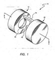
- the vacuum vessel 60 is spaced apart from and hermetically encloses the thermal shield 58. It is noted that the first support post 42 and the first dewar conduit 46 are disposed inside a first portion 76 of the vacuum vessel 60, that the second support post and the second dewar conduit are disposed inside a second portion 78 of the vacuum vessel, and that such first and second portions 76 and 78 of the vacuum vessel 60 are shown in Figure 1 .
- the magnet 10 would include the previously-described cryogenic fluid 64 and magnetic resonance imaging volume (also known as just "imaging volume”) 66.
- first 42 and second support posts are angularly spaced apart between generally 110 and 150 degrees about the axis 12 and disposed radially outward from the imaging volume 66. In one example an angular spacing of generally 130 degrees is provided for convenient placement of the patient (not shown) in the imaging volume 66.
- the open magnet 10 has a magnetic field within its imaging volume 66 of generally 1.4 to 1.5 Tesla.
- the first and second portions 76 and 78 of the vacuum vessel 60 are horizontally aligned (as shown in Figure 1 ), and the patient would typically be in a standing position within the imaging volume 66.
- the first and second portions 76 and 78 of the vacuum vessel 60 are vertically aligned, and the patient would typically be lying on a patient table within the imaging volume 66.
- pole pieces 18 and 30 provide the main structural support of the magnet 10 including the coils 16, 28, 68, and 70 and the dewars 20 and 32, and that the pole pieces 18 and 30 are shaped (e.g., have ring steps) to provide a more uniform magnetic field within the imaging volume 66. Any further correction of magnetic field inhomogeneities may be accomplished by active shimming, as is within the skill of the artisan. It is further noted that in the example shown in the figures, magnet 10 is designed for each assembly 14 and 26 to have a recess 80 in the vacuum vessel 60 facing the imaging volume 66 for a split pair of flat shielded gradient/RF coils, wherein the pole faces of the pole pieces 18 and 30 are not laminated, as can be appreciated by the artisan.
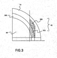
- FIG. 3 there is shown a cross-sectional view of a support post configuration according to the present invention.
- the support posts are shown as first support post 42 in Figure 1 and a second support post is not in view but identical to first support post of the open magnet system.
- the magnet assembly system of Figure 1 comprises a first assembly 14 and a second assembly 26 opposing each other in a longitudinally spaced apart relationship.
- the first and second assemblies generating a static magnetic field for use in MR imaging.
- Figure 3 shows first assembly 14 only, but it is appreciated that second assembly 26 is identical.
- Ring 300 is typically on the outer surface of first assembly 14 and second assembly 26, and is on the surface facing the imaging volume 66.
- the magnet system further comprises support post 42 (and a second post not shown in the cross-sectional view of Figure 3 ).
- Support post 42 comprises a first support element 310, which is a support post such as described with reference to Figures 1 and 2 , and a second support element 320 attached to first support element 310 on the surface away from imaging volume 66 (hereinafter referred to as the "back").
- second support element 320 and first support element 310 form support post 42.
- Second support element 320 may be welded to first support element 310 and further welded, or similarly attached, to ring 300 for added support. It is to be appreciated that this embodiment is useful for modifying existing open MRI systems in order to reduce vibration.
- the support posts as described above are configured to reduce vibration.
- the bending of the support post deflects the top magnetic pole by the angle ⁇ (theta) that creates magnetic field variation detected in imaging.
- the support post neutral axis is a distance off center (30 cm in a typical configuration)
- the angle influences the vibration amplitude of the center distance between the gap between first and second assemblies 14 and 26, respectfully.
- the additional material of second support element 320 displaces the exterior post boundary toward the back on the MRI system along the y-direction.
- Torque on the poles by the applied imaging gradient bends the post and the moment of inertia of the magnetic poles and the spring constant of the post gives a 30 Hz resonance. This increases the moment of inertia by a factor of 10 and stiffens the post. Additionally, this raises the resonance frequency and reduces the amplitude of vibration.
- a method for reducing vibration in open MRI comprises attaching a second support element to each of the support posts on a surface away from the imaging volume as described above. It is to be appreciated that this method may be applicable for existing open MRI systems as a modification for reducing vibration and vibration effects.
Description
- This invention relates generally to an open magnetic resonance imaging (MRI) magnet system, and more particularly to the support structures contained within the open magnet assembly.
- Open MRI magnets are generally made with two magnetic pole pieces in the shape of thick disks. For a horizontal open magnet, the pole pieces are arranged with an upper horizontal pole and a lower horizontal pole. The imaging subject is inserted in the gap between the poles. Another arrangement has the planes of the pole pieces (often referred to as "double donut") with the patient inserted through holes in the center of the pole pieces (the "donut holes"). In this arrangement, a physician or other attendant can stand between the donuts and thereby have access to the patient.
- Typically, there are strong magnetic forces between the pole pieces and, in the case of the horizontal magnet arrangement, the upper pole piece has considerable weight and must be supported. It is convenient to have strong and substantially stiff support posts between the pole pieces. It is desirable to have the posts confined to as narrow an angular region as possible to enhance the openness of the scanner. Narrow posts, however, are prone to vibration, which in turn affects imaging.
- In higher field magnet systems, such as 0.7 Tesla (T) and above, vibration of support posts may be detected during imaging with a fast spin echo sequence. The effect is caused by the periodic application of imaging gradients that produce a resonance with the mechanical systems of the MRI system. As the support posts bend slightly, the magnetic field in the imaging volume is perturbed.
- In
US-A-6,166,617 there is described a magnet assembly system for use in an MRI system generally in accordance with the preamble of claim 1 hereof. - What is needed is a magnet arrangement for open MRI systems that reduces vibrations that affect imaging while maintaining the desirable openness of such systems.
- According to the present invention, there is provided a magnet assembly system for use in an open Magnetic Resonance Imaging (MRI) system comprising: a first assembly and a second assembly for generating a static magnetic field, each assembly comprising a superconductive main coil and a magnetizable pole piece, the first and second assemblies opposing each other in a longitudinally spaced apart relationship in the direction of said generated static magnetic field, with most of the pole piece of each assembly being disposed radially inward of its main coil; a plurality of support posts between the first and second assemblies for maintaining the first and second assemblies in said spaced apart relationship in said longitudinal direction of said generated static magnetic field, and for maintaining an open imaging volume between the first and second assemblies and for further providing structural support, each of the support posts comprising a first support element attached between the pole pieces of the first and second assemblies and disposed radially outward from the imaging volume, characterised by each of said support posts comprising a second support element attached radially outward to the back surface of the first support element and thereby stiffening the first support element and reducing vibration during imaging, the second support element displacing the exterior post boundary radially outward.
- The features and advantages of the present invention will become apparent from the following detailed description of the invention when read with the accompanying drawings in which:
-
Figure 1 is a schematic perspective view of an embodiment of the magnet of the invention; -
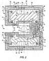
Figure 2 is a schematic cross sectional view of the magnet ofFigure 1 taken along lines 2-2 ofFigure 1 ; and, -
Figure 3 is a schematic cross-sectional view of a support post to which embodiments of the present invention are applicable. - Referring now to the drawings, wherein like numerals represent like elements throughout,
Figures 1-2 show an embodiment of themagnet 10 of the present invention. In one application,magnet 10 provides the static magnetic field for a magnetic resonance imaging (MRI) system (not shown) used in medical diagnostics. It is noted that in describing the invention, when a magnet is said to include a component such as a coil, a pole piece, or a dewar, etc., it is understood to mean that the magnet includes at least one coil, at least one pole piece, or at least one dewar, etc. - In a first embodiment, a
superconductive magnet 10 includes a longitudinally-extendingaxis 12 and afirst assembly 14. Thefirst assembly 14 includes a superconductivemain coil 16 and amagnetizable pole piece 18. Themain coil 16 is generally coaxially aligned with theaxis 12, carries a first main electric current in a first direction, and is disposed a first radial distance from theaxis 12. The first direction is defined to be either a clockwise or a counterclockwise circumferential direction about theaxis 12 with any slight longitudinal component of current direction being ignored. Thepole piece 18 is generally coaxially aligned with theaxis 12, and is spaced apart from themain coil 16 of thefirst assembly 14, Most of thepole piece 18 of thefirst assembly 14 is disposed radially inward of themain coil 16 of thefirst assembly 14. Thepole piece 18 of thefirst assembly 14 extends from theaxis 12 radially outward a distance equal to at least 75 percent of the first radial distance. During operation of themagnet 10, thepole piece 18 of thefirst assembly 14 has a temperature equal generally to that of themain coil 16 of thefirst assembly 14. It is noted that thefirst assembly 14 may be used alone as a table magnet (not shown) or may be one of two assemblies of an open magnet (as shown in the figures). During operation of themagnet 10, themain coil 16 and thepole piece 18 of thefirst assembly 14 are cooled by a cryocooler coldhead (not shown), and/or by a cryogenic fluid, or the like. - In a second embodiment, a
superconductive magnet 10 includes a longitudinally-extendingaxis 12 and afirst assembly 14. Thefirst assembly 14 includes a superconductivemain coil 16, amagnetizable pole piece 18, and a cryogenic-fluid dewar 20. The superconductivemain coil 16 is generally coaxially aligned with theaxis 12 and carries a first main electric current in a first direction. Thepole piece 18 is generally coaxially aligned with theaxis 12, is spaced apart from themain coil 16, and has asurface portion 22. Most of thepole piece 18 is disposed radially inward of themain coil 16. Thedewar 20 encloses themain coil 16 and has aninterior surface 24 defined in part by thesurface portion 22 of thepole piece 18. - In particular magnet designs, additional superconductive main coils (not shown) may be needed in the
first assembly 14 to achieve a high magnetic field strength, within the magnet's imaging volume, without exceeding the critical current density of the superconductor being used in the superconductive coils, as is known to those skilled in the art. An example of a superconductor for the superconductivemain coil 16 is niobium-titanium. An example of a material for thepole piece 18 is iron. - In one example, the
magnet 10 also includes asecond assembly 26 longitudinally spaced apart from thefirst assembly 14. Thesecond assembly 26 includes a superconductivemain coil 28, amagnetizable pole piece 30, and a cryogenic-fluid dewar 32. The superconductivemain coil 28 is generally coaxially aligned with theaxis 12 and carries a first main electric current in the previously-described first direction. Thepole piece 30 is generally coaxially aligned with theaxis 12, is spaced apart from themain coil 28, and has asurface portion 34. Most of thepole piece 30 is disposed radially inward of themain coil 28. Thedewar 32 encloses themain coil 28 and has aninterior surface 36 defined in part by thesurface portion 34 of thepole piece 30. In the example shown infigures 1 and2 , thepole piece 18 includes anothersurface portion 23 which does not help define theinterior surface 24 of thedewar 20, and thepole piece 30 includes another surface portion 35 which does not help define theinterior surface 36 of thedewar 32. - In one construction, the
magnet 10 also includes a generally-nonmagnetizable coil support 38 attached to thepole piece 18 and supporting themain coil 16 of thefirst assembly 14 and further includes a generally-nonmagnetizable coil support 40 attached to thepole piece 30 and supporting themain coil 28 of thesecond assembly 26. By "nonmagnetizable" is meant being able to be magnetized no better than nonmagnetic stainless steel. An example of a material for the coil supports 38 and 40 is nonmagnetic stainless steel or fiberglass. - In one magnet design, the
magnet 10 also includes a generally-nonmagnetizable (first)support post 42 having a first end structurally attached (e.g., welded) to thepole piece 18 of thefirst assembly 14, having a second end structurally attached (e.g., welded) to thepole piece 30 of thesecond assembly 26, and having asurface portion 44. An example of a material for the (first)support post 42 is nonmagnetic stainless steel. In this design, themagnet 10 further includes a (first)dewar conduit 46 in fluid communication with thedewar 20 of thefirst assembly 14 and thedewar 32 of thesecond assembly 26. The (first)dewar conduit 46 has an interior surface 48 defined in part by thesurface portion 44 of the (first)support post 42. Here, aplate assembly 50 has an interior surface including afirst portion 52 defining in part the interior surface of thedewar 20 of thefirst assembly 14, asecond portion 54 defining in part the interior surface of thedewar 32 of thesecond assembly 26, and athird portion 56 defining in part the interior surface of the (first)dewar conduit 46. In this example, themagnet 10 additionally includes athermal shield 58 and avacuum vessel 60. Thethermal shield 58 is spaced apart from and generally encloses thepole piece dewar second assemblies support post 42, and the (first)dewar conduit 46. Thevacuum vessel 60 is spaced apart from and hermetically encloses thethermal shield 58. An example of a material for theplate assembly 50, thethermal shield 58, and thevacuum vessel 60 is nonmagnetic stainless steel. It is noted that, in this example, the previously-mentioned "spacing apart" is accomplished by usingconventional spacers 62. - In operation, the
magnet 10 would includecryogenic fluid 64 disposed in thedewar second assemblies dewar conduit 46. An example of a cryogenic fluid is liquid helium. A cryocooler coldhead (not shown) may be used to recondense -evaporated liquid helium by having the first stage of the coldhead be in contact with thethermal shield 58 and by having the second stage of the coldhead penetrate into the dewar void volume near the highest point of adewar second assemblies assemblies cryogenic fluid 64 would be disposed only in thedewar second assemblies dewar conduit 46. In the embodiment shown inFigures 1 and2 , themagnet 10 also includes a magneticresonance imaging volume 66 having a center located generally on theaxis 12 longitudinally equidistant between the first andsecond assemblies imaging volume 66 is a sphere. It is noted that typically thesecond assembly 26 is a general mirror image of thefirst assembly 14 about a plane (not sown) which is perpendicular to theaxis 12 and which is disposed generally equidistant between the first andsecond assemblies - In a third and exemplary embodiment, a superconductive
open magnet 10 includes a longitudinally-extendingaxis 12, afirst assembly 14, and asecond assembly 26 longitudinally spaced apart from thefirst assembly 14. Thefirst assembly 14 includes a superconductivemain coil 16, asuperconductive shielding coil 68, a magnetizable and generally cylindrical-shapedpole piece 18, and a cryogenic-fluid dewar 20. The superconductivemain coil 16 is generally coaxially aligned with theaxis 12 and carries a first main electric current in a first direction. Thesuperconductive shielding coil 68 is generally coaxially aligned with theaxis 12, is disposed longitudinally outward from themain coil 16, and carries a first shielding electric current in an opposite direction to the previously-described first direction. Thepole piece 18 is generally coaxially aligned with and intersects theaxis 12, is spaced apart from the main and shieldingcoils surface portion 22. Most of thepole piece 18 is disposed longitudinally between and radially inward of the main and shieldingcoils dewar 20 encloses the main and shieldingcoils interior surface 24 defined in part by thesurface portion 22 of thepole piece 18. Thesecond assembly 26 includes a superconductivemain coil 28, asuperconductive shielding coil 70, a magnetizable and generally cylindrical-shapedpole piece 30, and a cryogenic-fluid dewar 32. The superconductivemain coil 28 is generally coaxially aligned with theaxis 12 and carries a second main electric current in the previously-described first direction. Thesuperconductive shielding coil 70 is generally coaxially aligned with theaxis 12, is disposed longitudinally outward from themain coil 28, and carries a second shielding electric current in the previously-described opposite direction. Thepole piece 30 is generally coaxially aligned with and intersects theaxis 12, is spaced apart from the main and shieldingcoils surface portion 34. Most of thepole piece 30 is disposed longitudinally between and radially inward of the main and shieldingcoils dewar 32 encloses the main and shieldingcoils interior surface 36 defined in part by thesurface portion 34 of thepole piece 30. - In one construction, the
open magnet 10 also includes generally-nonmagnetizable coil supports 38 and 72 attached to thepole piece 18 and supporting the main and shieldingcoils first assembly 14 and further includes generally-nonmagnetizable coil supports 40 and 74 attached to thepole piece 30 and supporting the main and shieldingcoils second assembly 26. In one magnet design, theopen magnet 10 also includes generally-nonmagnetizable first 42 and second (not shown but identical with the first 42) support posts each having a first end structurally attached to thepole piece 18 of thefirst assembly 14, each having a second end structurally attached to thepole piece 30 of thesecond assembly 26, and each having asurface portion 44. In this design, theopen magnet 10 further includes first 46 and second (not shown but identical with the first 46) dewar conduits each in fluid communication with thedewar 20 of thefirst assembly 14 and thedewar 32 of thesecond assembly 26. Thefirst dewar conduit 46 has an interior surface 48 defined in part by thesurface portion 44 of thefirst support post 42, and the second dewar conduit has an interior surface defined in part by the surface portion of the second support post. In this example, theopen magnet 10 additionally includes athermal shield 58 and avacuum vessel 60. Thethermal shield 58 is spaced apart from and generally encloses thepole piece dewar second assemblies vacuum vessel 60 is spaced apart from and hermetically encloses thethermal shield 58. It is noted that thefirst support post 42 and thefirst dewar conduit 46 are disposed inside afirst portion 76 of thevacuum vessel 60, that the second support post and the second dewar conduit are disposed inside asecond portion 78 of the vacuum vessel, and that such first andsecond portions vacuum vessel 60 are shown inFigure 1 . In operation, themagnet 10 would include the previously-described cryogenic fluid 64 and magnetic resonance imaging volume (also known as just "imaging volume") 66. In one construction, the first 42 and second support posts (as seen from the enclosing first andsecond portions vacuum vessel 60 shown inFigure 1 ) are angularly spaced apart between generally 110 and 150 degrees about theaxis 12 and disposed radially outward from theimaging volume 66. In one example an angular spacing of generally 130 degrees is provided for convenient placement of the patient (not shown) in theimaging volume 66. - In one application, the
open magnet 10 has a magnetic field within itsimaging volume 66 of generally 1.4 to 1.5 Tesla. In one orientation of theopen magnet 10, the first andsecond portions vacuum vessel 60 are horizontally aligned (as shown inFigure 1 ), and the patient would typically be in a standing position within theimaging volume 66. In another orientation (not shown) of theopen magnet 10, the first andsecond portions vacuum vessel 60 are vertically aligned, and the patient would typically be lying on a patient table within theimaging volume 66. It is noted that thepole pieces magnet 10 including thecoils dewars pole pieces imaging volume 66. Any further correction of magnetic field inhomogeneities may be accomplished by active shimming, as is within the skill of the artisan. It is further noted that in the example shown in the figures,magnet 10 is designed for eachassembly recess 80 in thevacuum vessel 60 facing theimaging volume 66 for a split pair of flat shielded gradient/RF coils, wherein the pole faces of thepole pieces - Referring now to
Figure 3 , there is shown a cross-sectional view of a support post configuration according to the present invention. Here the support posts are shown asfirst support post 42 inFigure 1 and a second support post is not in view but identical to first support post of the open magnet system. Referring further toFigure 3 , the magnet assembly system ofFigure 1 comprises afirst assembly 14 and asecond assembly 26 opposing each other in a longitudinally spaced apart relationship. The first and second assemblies generating a static magnetic field for use in MR imaging.Figure 3 showsfirst assembly 14 only, but it is appreciated thatsecond assembly 26 is identical. On a surface of first assembly 14 (and on an opposing surface of second assembly 26), there is typically aring 300 to which components such assupport post 42 is mounted thereon.Ring 300 is typically on the outer surface offirst assembly 14 andsecond assembly 26, and is on the surface facing theimaging volume 66. The magnet system further comprises support post 42 (and a second post not shown in the cross-sectional view ofFigure 3 ).Support post 42 comprises afirst support element 310, which is a support post such as described with reference toFigures 1 and2 , and asecond support element 320 attached tofirst support element 310 on the surface away from imaging volume 66 (hereinafter referred to as the "back"). In the embodiment shown inFigure 3 ,second support element 320 andfirst support element 310form support post 42.Second support element 320 may be welded tofirst support element 310 and further welded, or similarly attached, to ring 300 for added support. It is to be appreciated that this embodiment is useful for modifying existing open MRI systems in order to reduce vibration. - The support posts as described above are configured to reduce vibration. The curvature I/R induced by a bending moment M on a support post depends on the moment of inertia of the cross section I and on the modulus of elasticity E given by the equation M=EI/R. In the high field open geometry, the bending of the support post deflects the top magnetic pole by the angle θ (theta) that creates magnetic field variation detected in imaging. Since the support post neutral axis is a distance off center (30 cm in a typical configuration), the angle influences the vibration amplitude of the center distance between the gap between first and
second assemblies Figure 3 , the additional material ofsecond support element 320 displaces the exterior post boundary toward the back on the MRI system along the y-direction. Torque on the poles by the applied imaging gradient bends the post and the moment of inertia of the magnetic poles and the spring constant of the post gives a 30 Hz resonance. This increases the moment of inertia by a factor of 10 and stiffens the post. Additionally, this raises the resonance frequency and reduces the amplitude of vibration. - A method for reducing vibration in open MRI comprises attaching a second support element to each of the support posts on a surface away from the imaging volume as described above. It is to be appreciated that this method may be applicable for existing open MRI systems as a modification for reducing vibration and vibration effects.
Claims (1)
- A magnet assembly system for use in an open Magnetic Resonance Imaging (MRI) system comprising:a first assembly (14) and a second assembly (26) for generating a static magnetic field, each assembly comprising a superconductive main coil (16, 28) and a magnetizable pole piece (18,30), the first and second assemblies opposing each other in a longitudinally spaced apart relationship in the direction of said generated static magnetic field, with most of the pole piece of each assembly being disposed radially inward of its main coil;a plurality of support posts (42) between the first and second assemblies for maintaining the first and second assemblies in said spaced apart relationship in said longitudinal direction of said generated static magnetic field, and for maintaining an open imaging volume (66) between the first and second assemblies and for further providing structural support, each of the support posts comprising a first support element (310) attached between the pole pieces (18, 30) of the first and second assemblies and disposed radially outward from the imaging volume (66), characterised byeach of said support posts comprising a second support element (320) attached radially outward to the back surface of the first support element and thereby stiffening the first support element and reducing vibration during imaging, the second support element displacing the exterior post boundary radially outward.
Applications Claiming Priority (2)
| Application Number | Priority Date | Filing Date | Title |
|---|---|---|---|
| US09/683,415 US6504372B1 (en) | 2001-12-24 | 2001-12-24 | High field open magnetic resonance magnet with reduced vibration |
| US683415 | 2001-12-24 |
Publications (2)
| Publication Number | Publication Date |
|---|---|
| EP1324064A1 EP1324064A1 (en) | 2003-07-02 |
| EP1324064B1 true EP1324064B1 (en) | 2008-05-28 |
Family
ID=24743953
Family Applications (1)
| Application Number | Title | Priority Date | Filing Date |
|---|---|---|---|
| EP02258880A Expired - Fee Related EP1324064B1 (en) | 2001-12-24 | 2002-12-23 | High field open magnetic resonance magnet with reduced vibration |
Country Status (4)
| Country | Link |
|---|---|
| US (1) | US6504372B1 (en) |
| EP (1) | EP1324064B1 (en) |
| JP (1) | JP4152737B2 (en) |
| DE (1) | DE60226834D1 (en) |
Families Citing this family (4)
| Publication number | Priority date | Publication date | Assignee | Title |
|---|---|---|---|---|
| CN1237938C (en) * | 2001-03-14 | 2006-01-25 | 株式会社日立医药 | Magnetic resonance imaging apparatus and static magnetic field generating apparats used therefor |
| JP3790971B2 (en) | 2004-06-23 | 2006-06-28 | 株式会社日立製作所 | Magnetic resonance imaging system |
| JP4639763B2 (en) * | 2004-11-12 | 2011-02-23 | 三菱電機株式会社 | Magnetic resonance imaging system |
| JP4866213B2 (en) * | 2006-11-15 | 2012-02-01 | 株式会社日立製作所 | Superconducting magnet apparatus and magnetic resonance imaging apparatus |
Family Cites Families (8)
| Publication number | Priority date | Publication date | Assignee | Title |
|---|---|---|---|---|
| IL106779A0 (en) * | 1992-09-11 | 1993-12-08 | Magna Lab Inc | Permanent magnetic structure |
| US5754085A (en) * | 1992-09-28 | 1998-05-19 | Fonar Corporation | Ferromagnetic yoke magnets for medical magnetic resonance studies |
| US5381122A (en) * | 1994-01-14 | 1995-01-10 | General Electric Company | Open MRI magnet having a support structure |
| JP2000139874A (en) * | 1998-09-02 | 2000-05-23 | Sumitomo Special Metals Co Ltd | Magnetic field generator for mri |
| US6169404B1 (en) * | 1998-12-18 | 2001-01-02 | General Electric Company | Vibration cancellation for C-shaped superconducting magnet |
| US6172588B1 (en) | 1999-04-23 | 2001-01-09 | General Electric Company | Apparatus and method for a superconductive magnet with pole piece |
| US6166617A (en) * | 1999-11-09 | 2000-12-26 | General Electric Company | Pole piece assembly and open magnet having same |
| US6201462B1 (en) * | 1999-11-09 | 2001-03-13 | General Electric Company | Open superconductive magnet having a cryocooler coldhead |
-
2001
- 2001-12-24 US US09/683,415 patent/US6504372B1/en not_active Expired - Fee Related
-
2002
- 2002-12-20 JP JP2002369123A patent/JP4152737B2/en not_active Expired - Fee Related
- 2002-12-23 DE DE60226834T patent/DE60226834D1/en not_active Expired - Lifetime
- 2002-12-23 EP EP02258880A patent/EP1324064B1/en not_active Expired - Fee Related
Also Published As
| Publication number | Publication date |
|---|---|
| JP2003220050A (en) | 2003-08-05 |
| US6504372B1 (en) | 2003-01-07 |
| JP4152737B2 (en) | 2008-09-17 |
| EP1324064A1 (en) | 2003-07-02 |
| DE60226834D1 (en) | 2008-07-10 |
Similar Documents
| Publication | Publication Date | Title |
|---|---|---|
| US5936498A (en) | Superconducting magnet apparatus and magnetic resonance imaging system using the same | |
| US5410287A (en) | Open MRI magnet with uniform magnetic field | |
| US6933722B2 (en) | Magnetic resonance imaging device and gradient magnetic field coil used for it | |
| EP2179300B1 (en) | Magnet assembly | |
| JP3615119B2 (en) | Apparatus and method for superconducting magnet with pole pieces | |
| EP1610143B1 (en) | Magnetic resonance imaging apparatus | |
| EP0837339A1 (en) | Planar superconducting MRI magnet | |
| US7126448B2 (en) | Superconducting magnet apparatus and magnetic resonance imaging apparatus using the same | |
| US5574417A (en) | Open MRI magnet with homogeneous imaging volume | |
| EP0770883B1 (en) | Cryogenic-fluid-cooled open MRI magnet with uniform magnetic field | |
| EP0982598B1 (en) | Magnetic resonance system with shim rings | |
| EP0770882B1 (en) | Open MRI superconductive magnet with cryogenic-fluid cooling | |
| US6201462B1 (en) | Open superconductive magnet having a cryocooler coldhead | |
| US6950001B2 (en) | Superconducting open MRI magnet with transverse magnetic field | |
| US6198371B1 (en) | Open magnet with floor mount | |
| US7112966B2 (en) | Magnetic resonance imaging apparatus | |
| EP0609604A1 (en) | Magnetic field generation device of use in superconductive type MRI | |
| EP1324064B1 (en) | High field open magnetic resonance magnet with reduced vibration | |
| US20030110564A1 (en) | Magnetic resonance imaging apparatus | |
| US20110037469A1 (en) | Electromagnet Device and Magnetic Resonance Imaging Device | |
| JP2005512646A (en) | Gradient coil arrangement structure | |
| US4673881A (en) | Magnetic apparatus of a nuclear spin tomography system with an approximately hollow-cylindrical shielding device | |
| JP2006141613A (en) | Magnet system and magnetic resonance image diagnostic apparatus | |
| JP2006141614A (en) | Magnet system, method of installing magnet system, and magnetic resonance image diagnostic apparatus | |
| JPH0847488A (en) | Magnetostatic field magnet apparatus for magnetic resonance imaging |
Legal Events
| Date | Code | Title | Description |
|---|---|---|---|
| PUAI | Public reference made under article 153(3) epc to a published international application that has entered the european phase |
Free format text: ORIGINAL CODE: 0009012 |
|
| AK | Designated contracting states |
Designated state(s): AT BE BG CH CY CZ DE DK EE ES FI FR GB GR IE IT LI LU MC NL PT SE SI SK TR |
|
| AX | Request for extension of the european patent |
Extension state: AL LT LV MK RO |
|
| 17P | Request for examination filed |
Effective date: 20040102 |
|
| AKX | Designation fees paid |
Designated state(s): DE GB NL |
|
| 17Q | First examination report despatched |
Effective date: 20060928 |
|
| 17Q | First examination report despatched |
Effective date: 20060928 |
|
| GRAP | Despatch of communication of intention to grant a patent |
Free format text: ORIGINAL CODE: EPIDOSNIGR1 |
|
| GRAS | Grant fee paid |
Free format text: ORIGINAL CODE: EPIDOSNIGR3 |
|
| GRAA | (expected) grant |
Free format text: ORIGINAL CODE: 0009210 |
|
| AK | Designated contracting states |
Kind code of ref document: B1 Designated state(s): DE GB NL |
|
| REG | Reference to a national code |
Ref country code: GB Ref legal event code: FG4D |
|
| REF | Corresponds to: |
Ref document number: 60226834 Country of ref document: DE Date of ref document: 20080710 Kind code of ref document: P |
|
| PLBE | No opposition filed within time limit |
Free format text: ORIGINAL CODE: 0009261 |
|
| STAA | Information on the status of an ep patent application or granted ep patent |
Free format text: STATUS: NO OPPOSITION FILED WITHIN TIME LIMIT |
|
| 26N | No opposition filed |
Effective date: 20090303 |
|
| PGFP | Annual fee paid to national office [announced via postgrant information from national office to epo] |
Ref country code: NL Payment date: 20091224 Year of fee payment: 8 |
|
| PGFP | Annual fee paid to national office [announced via postgrant information from national office to epo] |
Ref country code: GB Payment date: 20091229 Year of fee payment: 8 |
|
| PGFP | Annual fee paid to national office [announced via postgrant information from national office to epo] |
Ref country code: DE Payment date: 20091230 Year of fee payment: 8 |
|
| REG | Reference to a national code |
Ref country code: NL Ref legal event code: V1 Effective date: 20110701 |
|
| GBPC | Gb: european patent ceased through non-payment of renewal fee |
Effective date: 20101223 |
|
| REG | Reference to a national code |
Ref country code: DE Ref legal event code: R119 Ref document number: 60226834 Country of ref document: DE Effective date: 20110701 |
|
| PG25 | Lapsed in a contracting state [announced via postgrant information from national office to epo] |
Ref country code: GB Free format text: LAPSE BECAUSE OF NON-PAYMENT OF DUE FEES Effective date: 20101223 Ref country code: DE Free format text: LAPSE BECAUSE OF NON-PAYMENT OF DUE FEES Effective date: 20110701 |
|
| PG25 | Lapsed in a contracting state [announced via postgrant information from national office to epo] |
Ref country code: NL Free format text: LAPSE BECAUSE OF NON-PAYMENT OF DUE FEES Effective date: 20110701 |