EP1323947A2 - Magnetorheologische Kolben und Dämpfer - Google Patents
Magnetorheologische Kolben und Dämpfer Download PDFInfo
- Publication number
- EP1323947A2 EP1323947A2 EP02079986A EP02079986A EP1323947A2 EP 1323947 A2 EP1323947 A2 EP 1323947A2 EP 02079986 A EP02079986 A EP 02079986A EP 02079986 A EP02079986 A EP 02079986A EP 1323947 A2 EP1323947 A2 EP 1323947A2
- Authority
- EP
- European Patent Office
- Prior art keywords
- passageway
- throat
- energizable
- substantially magnetically
- magnetorheological piston
- Prior art date
- Legal status (The legal status is an assumption and is not a legal conclusion. Google has not performed a legal analysis and makes no representation as to the accuracy of the status listed.)
- Granted
Links
- 239000000463 material Substances 0.000 claims description 6
- 230000014509 gene expression Effects 0.000 description 20
- 238000010276 construction Methods 0.000 description 11
- 239000012530 fluid Substances 0.000 description 9
- 238000013016 damping Methods 0.000 description 3
- 230000000694 effects Effects 0.000 description 3
- 230000004048 modification Effects 0.000 description 3
- 238000012986 modification Methods 0.000 description 3
- 241001503987 Clematis vitalba Species 0.000 description 1
- 239000006096 absorbing agent Substances 0.000 description 1
- 239000012212 insulator Substances 0.000 description 1
- 238000002955 isolation Methods 0.000 description 1
- 230000014759 maintenance of location Effects 0.000 description 1
- 239000000615 nonconductor Substances 0.000 description 1
- 230000035939 shock Effects 0.000 description 1
- 238000004804 winding Methods 0.000 description 1
Images


Classifications
-
- F—MECHANICAL ENGINEERING; LIGHTING; HEATING; WEAPONS; BLASTING
- F16—ENGINEERING ELEMENTS AND UNITS; GENERAL MEASURES FOR PRODUCING AND MAINTAINING EFFECTIVE FUNCTIONING OF MACHINES OR INSTALLATIONS; THERMAL INSULATION IN GENERAL
- F16F—SPRINGS; SHOCK-ABSORBERS; MEANS FOR DAMPING VIBRATION
- F16F9/00—Springs, vibration-dampers, shock-absorbers, or similarly-constructed movement-dampers using a fluid or the equivalent as damping medium
- F16F9/32—Details
- F16F9/53—Means for adjusting damping characteristics by varying fluid viscosity, e.g. electromagnetically
- F16F9/535—Magnetorheological [MR] fluid dampers
Definitions
- the present invention relates generally to piston dampers, and more particularly to a magnetorheological (MR) piston and damper.
- MR magnetorheological
- Conventional piston dampers include MR dampers having a cylinder containing an MR fluid and having an MR piston which slideably engages the cylinder.
- the MR fluid passes through an orifice of the MR piston.
- Exposing the MR fluid in the orifice to a varying magnetic field, generated by providing a varying electric current to an electric coil of the MR piston varies the damping effect of the MR fluid in the orifice providing variably-controlled damping of relative motion between the MR piston and the cylinder.
- the electric current is varied to accommodate varying operating conditions, as is known to those skilled in the art.
- a rod has a first end attached to the MR piston and a second end extending outside the cylinder. The cylinder and the rod are attached to separate structures to dampen relative motion of the two structures along the direction of piston travel.
- a known design includes an MR piston having a substantially annular, magnetically energizable passageway and a magnetically non-energizable passageway positioned radially inward from the magnetically energizable passageway.
- the magnetically non-energizable passageway includes a check valve which is in either a valve closed position or a valve open position. The check valve blocks flow in one direction (usually when the rod moves more outward from the cylinder). The check valve allows flow in the other direction (usually when the rod moves more inward into the cylinder).
- the flow cross-sectional area of the magnetically non-energizable passageway is chosen for a particular damper application.
- a magnetorheological piston in a first expression of an embodiment of the invention, includes a magnetorheological piston body having a substantially magnetically energizable passageway and having a substantially magnetically non-energizable passageway spaced apart from the magnetically energizable passageway.
- the substantially magnetically non-energizable passageway has a valveless passageway throat and has a flow cross-sectional area which has a minimum at the passageway throat and which is larger away from the passageway throat.
- An alternate first expression is for a magnetorheological damper including a cylinder and the magnetorheological piston of the previously-described first expression.
- the magnetorheological piston is positioned within, and slideably engages, the cylinder.
- a magnetorheological piston in a second expression of an embodiment of the invention, includes a magnetorheological piston body having a longitudinal axis, having a substantially magnetically energizable passageway substantially coaxially aligned with the longitudinal axis, and having a substantially magnetically non-energizable passageway spaced apart radially inward from the substantially magnetically energizable passageway.
- the substantially magnetically non-energizable passageway has a valveless passageway throat and has a flow cross-sectional area which has a minimum at the passageway throat and which is larger away from the passageway throat.
- a magnetorheological piston in a third expression of an embodiment of the invention, includes a magnetorheological piston body having a longitudinal axis, having a core with an electrical coil, having a longitudinal end plate attached to the core, having a substantially magnetically energizable passageway substantially coaxially aligned with the longitudinal axis, and having a substantially magnetically non-energizable passageway spaced apart radially inward from the substantially magnetically energizable passageway.
- the substantially magnetically non-energizable passageway has a core portion and a longitudinal end plate portion.
- the substantially magnetically non-energizable passageway has a valveless passageway throat and has a flow cross-sectional area which has a minimum at the passageway throat and which is larger away from the passageway throat.
- An alternate third expression is for a magnetorheological damper including a cylinder and the magnetorheological piston of the previously-described third expression.
- the magnetorheological piston is positioned within, and slideably engages, the cylinder.
- Having the substantially magnetically non-energizable passageway with a smaller flow cross-sectional area at a passageway throat and with a larger flow cross-sectional area away from the passageway throat limits the length of flow restriction to the length of a short passageway throat which prevents unwanted damper performance characteristics at low temperature (due to the high viscosity of low-temperature MR fluid), as can be appreciated by those skilled in the art.
- Locating the substantially magnetically non-energizable passageway also known as the by-pass) radially inward from the substantially magnetically energizable passageway reduces the unwanted MR effect of valving the MR fluid flow in the substantially magnetically non-energizable passageway.
- the magnetorheological piston body include a core with an electrical coil and include a longitudinal end plate attached to the core, wherein the substantially magnetically non-energizable passageway includes a core portion and a longitudinal end plate portion, allows the passageway throat to be created by a monolithic portion of the longitudinal end plate, an orifice plug positioned inside this passageway in the longitudinal end plate, an orifice tube positioned inside this passageway in the core, or an orifice disc positioned inside this passageway longitudinally between the core and the longitudinal end plate.
- An MR piston having a tunable substantially magnetically non-energizable passageway is obtained by choosing an appropriate longitudinal end plate, orifice plug, orifice tube, or orifice disc having a desired orifice for a particular MR damper application.
- Figure 1 shows a first embodiment of the present invention.
- a first expression of the first embodiment is for a magnetorheological piston 110 which is also known as a magnetorheological damper piston.
- An alternate first expression of the first embodiment is for a magnetorheological damper 112 which includes the magnetorheological piston 110.
- An application of the magnetorheological damper 112 is its use as a shock absorber for an automobile, an airplane, or other type of vehicle.
- Another application is use of the magnetorheological damper 112 to provide motion resistance on exercise equipment such as stair climbers and rowing machines.
- a further application is use of the magnetorheological damper 112 to provide motion isolation for a building, bridge, or other structure subject to earthquakes.
- An additional application is use of the magnetorheological damper 112 to dampen vibrations encountered by vehicles and structures in outer space. Other applications are left to the artisan.
- the magnetorheological piston 110 includes a magnetorheological piston body 114 having a substantially magnetically energizable passageway 116 and having a substantially magnetically non-energizable passageway 118 (also known as a by-pass) spaced apart from the substantially magnetically energizable passageway 116.
- the term "passageway" means a through passageway.
- the substantially magnetically non-energizable passageway 118 has a valveless passageway throat 120 and has a flow cross-sectional area which has a minimum at the passageway throat 120 and which is larger away from the passageway throat 120.
- the magnetorheological piston body 114 has a longitudinal axis 122, the substantially magnetically energizable passageway 116 is substantially coaxially aligned with the longitudinal axis 122, and the substantially magnetically non-energizable passageway 118 is disposed radially inward from the substantially magnetically energizable passageway 116.
- the substantially magnetically energizable passageway 116 is a substantially annularly cylindrical passageway having a flow cross-sectional shape of segments of a substantially circular ring.
- the substantially magnetically non-energizable passageway 118 is a cylindrical passageway having a flow cross--sectional shape of a circle apart from the passageway throat 120.
- the passageway throat 120 has a flow cross-sectional shape of a circle, a radially-aligned ellipse, or a circumferential arc segment. Other shapes are left to the artisan.
- the substantially magnetically non-energizable passageway 118 has a passageway length, and the passageway throat 120 has a throat length.
- the passageway length includes the throat length.
- the flow cross-sectional area of the passageway throat 120 is substantially constant along the throat length.
- the flow cross-sectional area of the substantially magnetically non-energizable passageway 118 apart from the passageway throat 120 is substantially constant along the passageway length.
- the magnetorheological piston body 114 has a core 124 with an electrical coil 126 and has a longitudinal end plate 128 attached to the core 124.
- the substantially magnetically non-energizable passageway 118 has a core portion 130 and a longitudinal end plate portion 132.
- the core portion 130 is that portion of the substantially magnetically non-energizable passageway 118 located in the core 124
- the longitudinal end plate portion 132 is that portion of the substantially magnetically non-energizable passageway 118 located in the longitudinal end plate 128.
- the longitudinal lengths of the core 124 and the longitudinal end plate 128 are left to the artisan.
- the magnetorheological piston body 114 includes a monolithic portion 134 bounding the passageway throat 120.
- the substantially magnetically non-energizable passageway 118 has two longitudinal ends, and the monolithic portion 134 is disposed substantially at one of the longitudinal ends.
- the longitudinal end plate 128 includes the monolithic portion 134.
- the longitudinal length of the monolithic portion 134 is less than one-tenth of the passageway length.
- the magnetorheological damper 112 includes a cylinder 136 and includes the magnetorheological piston 110 described in the fifth previous paragraph.
- the magnetorheological piston 110 is disposed within, and slideably engages, the cylinder 136.
- the previously described examples, constructions, designs, and variations of the magnetorheological piston 110 of the first expression are equally applicable to the magnetorheological damper 112 of the alternate first expression.
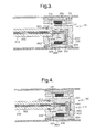
- the magnetorheological piston 210 also includes an orifice member 238 disposed inside the substantially magnetically non-energizable passageway 218 and bounding the passageway throat 220.
- the orifice member 238 is a member having an orifice which defines the passageway throat 220.
- the substantially magnetically non-energizable passageway 218 has two longitudinal ends, and the orifice member 238 is disposed substantially at one of the longitudinal ends.
- the orifice member 238 is an orifice plug 240 disposed inside the longitudinal end plate portion 232 of the substantially magnetically non-energizable passageway 218.
- the length of the orifice member 238 or the orifice plug 240 is less than half of the passageway length. In another design, the length of the orifice member 238 or the orifice plug 240 is less than one-tenth of the passageway length.
- the magnetorheological piston 310 also includes an orifice member 338 disposed inside the substantially magnetically non-energizable passageway 318 and bounding the passageway throat 320, wherein the substantially magnetically non-energizable passageway 318 has two longitudinal ends, and wherein the orifice member 338 is disposed between the longitudinal ends.
- the orifice member 338 is an orifice tube 342 disposed inside the core portion 330 of the substantially magnetically non-energizable passageway 318.
- the orifice tube 342 comprises (consists essentially of, or consists of) a magnetizable material.
- the orifice tube 342 becomes part of the magnetic circuit improving damping force capability in the substantially magnetically energizable passageway 316.
- the longitudinal placement of the orifice tube 342 relative to the electrical coil 326 is left to the artisan.
- the orifice tube 342 comprises (consists essentially of, or consists of) a non-magnetizable material.
- the length of the orifice member 338 or the orifice tube 342 is less than one-third of the passageway length.
- the magnetorheological piston 410 also includes an orifice disc 444 disposed between the core 424 and the longitudinal end plate 428 of the magnetorheological piston body 414 and bounding the passageway throat 420.
- the passageway throat 420 is radially inwardly bounded by the orifice disc 444.
- longitudinal flow occurs radially beyond the circumference of the orifice disc 444.
- An alignment tab 446 is shown on the orifice disc 444 in Figure 5.
- a first alternate embodiment of the orifice disc 544 is shown in Figure 6, wherein orifice disc 544 has a slot 546 bounding the passageway throat. In this orifice disc 544, longitudinal flow occurs through the slot 546.
- the slot 546 is a radially-elongated slot.
- a second alternate embodiment of the orifice disc 644 is shown in Figure 6, wherein the orifice disc 644 has a slot 646 which is a circumferentially-elongated slot which improves flow alignment through the substantially magnetically non-energizable passageway 418.
- a rod 648 is connected to the piston by a retention ring 650.
- An electrode 652 within the rod 648 is connected to a connector 654 (and protected by a seal 656) which is connected to an end of a wire 658 (which passes through a conduit of an electrical insulator 660 (such as a plastic insulator) whose windings create the electrical coil 126, 226, 326, and 426.
- Another longitudinal end plate 662 of the magnetorheological piston body is attached to the core 124, 224, 324, and 424 as shown in Figures 1-4.
- a piston ring 664 of the magnetorheological piston body is crimped over the longitudinal end plates 662, 128, 228, 328, and 428.
- Other constructions are left to the artisan. It is noted that MR fluid has been omitted from the figures for clarity.
- the orifice member 238 and 338 is secured by being press-fit, staked, or riveted.
- the substantially magnetically non-energizable passageway 118, 218, 318, and 418 is a valveless passageway.
- Having the substantially magnetically non-energizable passageway with a smaller flow cross-sectional area at a passageway throat and with a larger flow cross-sectional area away from the passageway throat limits the length of flow restriction to the length of a short passageway throat which prevents unwanted damper performance characteristics at low temperature (due to the high viscosity of low-temperature MR fluid), as can be appreciated by those skilled in the art.
- Locating the substantially magnetically non-energizable passageway also known as the by-pass) radially inward from the substantially magnetically energizable passageway reduces the unwanted MR effect of valving the MR fluid flow in the substantially magnetically non-energizable passageway.
- the magnetorheological piston body include a core with an electrical coil and include a longitudinal end plate attached to the core, wherein the substantially magnetically non-energizable passageway includes a core portion and a longitudinal end plate portion, allows the passageway throat to be created by a monolithic portion of the longitudinal end plate, an orifice plug positioned inside this passageway in the longitudinal end plate, an orifice tube positioned inside this passageway in the core, or an orifice disc positioned inside this passageway longitudinally between the core and the longitudinal end plate.
- An MR piston having a tunable substantially magnetically non-energizable passageway is obtained by choosing an appropriate longitudinal end plate, orifice plug, orifice tube, or orifice disc having a desired orifice for a particular MR damper application.
Landscapes
- Engineering & Computer Science (AREA)
- General Engineering & Computer Science (AREA)
- Physics & Mathematics (AREA)
- Electromagnetism (AREA)
- Mechanical Engineering (AREA)
- Fluid-Damping Devices (AREA)
Applications Claiming Priority (2)
| Application Number | Priority Date | Filing Date | Title |
|---|---|---|---|
| US34202 | 2001-12-27 | ||
| US10/034,202 US6612409B2 (en) | 2001-12-27 | 2001-12-27 | Magneotorheological piston and damper |
Publications (3)
| Publication Number | Publication Date |
|---|---|
| EP1323947A2 true EP1323947A2 (de) | 2003-07-02 |
| EP1323947A3 EP1323947A3 (de) | 2003-08-20 |
| EP1323947B1 EP1323947B1 (de) | 2006-05-24 |
Family
ID=21874931
Family Applications (1)
| Application Number | Title | Priority Date | Filing Date |
|---|---|---|---|
| EP02079986A Expired - Lifetime EP1323947B1 (de) | 2001-12-27 | 2002-11-28 | Magnetorheologische Kolben und Dämpfer |
Country Status (3)
| Country | Link |
|---|---|
| US (2) | US6612409B2 (de) |
| EP (1) | EP1323947B1 (de) |
| DE (1) | DE60211638T2 (de) |
Cited By (5)
| Publication number | Priority date | Publication date | Assignee | Title |
|---|---|---|---|---|
| EP1408253A3 (de) * | 2002-10-08 | 2004-06-16 | Delphi Technologies, Inc. | Magnetorheologischer Kolben mit Kern |
| WO2009149132A1 (en) * | 2008-06-02 | 2009-12-10 | Lord Corporation | Magneto-rheological fluid damper having enhanced on-state yield strength |
| CN102297232A (zh) * | 2011-08-22 | 2011-12-28 | 重庆仪表材料研究所 | 一种单出杆环型活塞磁流变阻尼器 |
| CN104100671A (zh) * | 2014-07-04 | 2014-10-15 | 中国人民解放军装甲兵工程学院 | 并联常通孔式磁流变阻尼器及其零场、有场阻尼力系数和阻尼力的求取方法 |
| CN105508494A (zh) * | 2015-12-30 | 2016-04-20 | 中国海洋大学 | 抗冲击磁流变阻尼器 |
Families Citing this family (30)
| Publication number | Priority date | Publication date | Assignee | Title |
|---|---|---|---|---|
| US6525289B2 (en) | 2001-02-01 | 2003-02-25 | Delphi Technologies, Inc. | Piston for magneto-rheological fluid systems and method for its manufacture |
| US6886819B2 (en) * | 2002-11-06 | 2005-05-03 | Lord Corporation | MR fluid for increasing the output of a magnetorheological fluid damper |
| US20040118646A1 (en) * | 2002-12-23 | 2004-06-24 | Delphi Technologies Inc | Magnetorheological damper assembly and piston |
| US6874603B2 (en) * | 2003-01-09 | 2005-04-05 | Delphi Technologies, Inc. | Magnetorheological piston and damper assembly |
| US6883649B2 (en) | 2003-03-21 | 2005-04-26 | Delphi Technologies, Inc. | Closing system for a magneto-rheological damper |
| US20040188197A1 (en) * | 2003-03-27 | 2004-09-30 | Ilya Lisenker | Piston plate for a magneto-rheological fluid damper |
| US6981577B2 (en) * | 2003-03-31 | 2006-01-03 | Kabushiki Kaisha Hitachi Seisakusho | Controlling damping force shock absorber |
| US6971231B2 (en) * | 2003-12-15 | 2005-12-06 | Delphi Technologies, Inc. | Piston and rod assembly and method |
| WO2005067613A2 (en) * | 2004-01-06 | 2005-07-28 | Deo Hrishikesh V | Suspension system with independent control of ride-height, stiffness and damping |
| US20060260891A1 (en) * | 2005-05-17 | 2006-11-23 | Kruckemeyer William C | Magnetorheological piston assembly and damper |
| US7878312B2 (en) * | 2006-05-31 | 2011-02-01 | University Of Maryland | Adaptive energy absorption system for a vehicle seat |
| US7822522B2 (en) * | 2006-05-31 | 2010-10-26 | Techno-Sciences, Inc. (corporation) | Adaptive energy absorption system for a vehicle seat |
| US7921973B2 (en) * | 2006-05-31 | 2011-04-12 | Techno-Sciences, Inc. | Adaptive energy absorption system for a vehicle seat |
| US7958979B2 (en) * | 2007-01-05 | 2011-06-14 | Honda Motor Co., Ltd. | Variable damper |
| KR100793394B1 (ko) * | 2007-01-29 | 2008-01-11 | 전북대학교산학협력단 | 자기유동유체를 이용한 헬스기구 |
| KR100892999B1 (ko) * | 2007-09-17 | 2009-04-10 | 에스앤티대우(주) | 연속 감쇠력 가변형 댐퍼의 피스톤밸브 어셈블리 |
| US8286763B2 (en) * | 2008-01-29 | 2012-10-16 | Bwi Company Limited S.A. | Magnetorheological fluid-based device having a magnetorheological piston assembly |
| US9074653B2 (en) * | 2008-10-21 | 2015-07-07 | GM Global Technology Operations LLC | Multistate switchable engine mount and system |
| US8327984B2 (en) * | 2009-10-30 | 2012-12-11 | Bwi Company Limited S.A. | Magnetorheological (MR) piston assembly with primary and secondary channels to improve MR damper force |
| JP5828558B2 (ja) * | 2012-03-01 | 2015-12-09 | Kyb株式会社 | 磁気粘性流体緩衝器 |
| DE102013103825A1 (de) | 2013-04-16 | 2014-10-16 | Dr. Ing. H.C. F. Porsche Aktiengesellschaft | Strebenelement für Kraftfahrzeuge |
| JP2015175515A (ja) * | 2014-03-18 | 2015-10-05 | カヤバ工業株式会社 | 磁気粘性流体緩衝器 |
| KR101686113B1 (ko) * | 2015-03-10 | 2016-12-13 | 주식회사 만도 | Mr 댐퍼 |
| WO2017112729A1 (en) | 2015-12-21 | 2017-06-29 | Lord Corporation | Improved seat-damping devices, systems, and methods |
| CN105402302B (zh) * | 2015-12-21 | 2017-05-10 | 吉林大学 | 集成空气弹簧的磁流变滑柱 |
| CN106286685B (zh) * | 2016-09-10 | 2018-02-06 | 西安科技大学 | 压电与电磁感应双重馈能式磁流变减振装置及其控制方法 |
| US10598248B2 (en) | 2017-11-01 | 2020-03-24 | Simon Fraser University | Smart fluid damper |
| CN108036014A (zh) * | 2017-12-21 | 2018-05-15 | 四川建筑职业技术学院 | 一种设有螺旋阻尼通道的磁流变阻尼器密封活塞 |
| US10711861B1 (en) * | 2019-03-19 | 2020-07-14 | The United States Of America As Represented By The Secretary Of The Navy | Controllable oleo-pneumatic damper using magnetorheological fluid |
| US11855379B2 (en) * | 2021-11-24 | 2023-12-26 | Caterpillar Inc. | Slidable nested conductors |
Family Cites Families (37)
| Publication number | Priority date | Publication date | Assignee | Title |
|---|---|---|---|---|
| DE2310614C2 (de) * | 1973-03-02 | 1986-10-23 | Douglas P. Grand Island N.Y. Taylor | Hydraulischer Stoßdämpfer |
| FR2592696B1 (fr) * | 1986-01-09 | 1989-12-01 | Aerospatiale | Contre-fiche de rappel elastique a amortissement incorpore, de type hydro-elastique. |
| US5018606A (en) * | 1990-01-10 | 1991-05-28 | Lord Corporation | Electrophoretic fluid damper |
| US5333708A (en) | 1993-01-11 | 1994-08-02 | General Motors Corporation | Compression cut-off valve for a hydraulic damper |
| US5510988A (en) | 1994-12-19 | 1996-04-23 | General Motors Corporation | Vehicle chassis control system |
| US5652704A (en) * | 1995-09-12 | 1997-07-29 | Lord Corporation | Controllable seat damper system and control method therefor |
| US6095486A (en) | 1997-03-05 | 2000-08-01 | Lord Corporation | Two-way magnetorheological fluid valve assembly and devices utilizing same |
| US6394239B1 (en) | 1997-10-29 | 2002-05-28 | Lord Corporation | Controllable medium device and apparatus utilizing same |
| US6171146B1 (en) | 1998-02-19 | 2001-01-09 | Delphi Technologies, Inc. | Repair method for dual lock multi-row electrical connector system |
| US6247951B1 (en) | 1998-05-29 | 2001-06-19 | Delphi Technologies, Inc. | Flexible circuit connector |
| DE19835670A1 (de) | 1998-08-06 | 2000-04-20 | Delphi Automotive Systems Gmbh | Dichtungsanordnung zwischen einem elektrischen Verbinder und einem elektrischen Leiter |
| US6142813A (en) | 1998-12-08 | 2000-11-07 | Delphi Technologies, Inc. | Electrical connector assembly |
| US6161662A (en) | 1999-03-16 | 2000-12-19 | Delphi Technologies, Inc. | Suspension damper for motor vehicle |
| US6086385A (en) | 1999-05-06 | 2000-07-11 | Delphi Technologies, Inc. | Connector assembly |
| US6162085A (en) | 1999-08-19 | 2000-12-19 | Delphi Technologies, Inc. | Electrical connector assembly for jumper cable |
| US6345706B1 (en) | 1999-09-13 | 2002-02-12 | Delphi Technologies, Inc. | Electrical coupling assembly for a magnetorheological damper |
| US6318519B1 (en) | 1999-09-13 | 2001-11-20 | Delphi Technologies, Inc. | Magnetorheological fluid damper tunable for smooth transitions |
| US6318520B1 (en) | 1999-09-13 | 2001-11-20 | Delphi Technologies, Inc. | Magnetorheological fluid damper tunable for smooth transitions |
| US6203364B1 (en) | 1999-10-12 | 2001-03-20 | Delphi Technologies, Inc. | Electrical connector having slide clip attachment |
| US6247965B1 (en) | 1999-12-06 | 2001-06-19 | Delphi Technologies, Inc. | Electrical connector having sealed snap-in locking cavity plugs |
| US6305957B1 (en) | 2000-02-24 | 2001-10-23 | Delphi Technologies, Inc. | Electrical connector assembly |
| US6406307B2 (en) | 2000-02-28 | 2002-06-18 | Delphi Technologies, Inc. | Annular electrical connector assembly |
| US6556118B1 (en) | 2000-03-03 | 2003-04-29 | Delphi Technologies, Inc. | Separate mount ignition coil utilizing a progressive wound secondary winding |
| US6208233B1 (en) | 2000-03-03 | 2001-03-27 | Delphi Technologies, Inc. | Trim resistor connector and sensor system |
| US6533588B1 (en) | 2000-03-30 | 2003-03-18 | Delphi Technologies, Inc. | Connector assembly for flexible circuits |
| US6535396B1 (en) | 2000-04-28 | 2003-03-18 | Delphi Technologies, Inc. | Combination circuit board and segmented conductive bus substrate |
| US6338651B1 (en) | 2000-08-10 | 2002-01-15 | Delphi Technologies, Inc. | Electrical connector assembly with seal |
| US6443137B1 (en) | 2000-09-08 | 2002-09-03 | Delphi Technologies, Inc. | Method of producing spark ignition assembly with integral spark plug and ignition coil |
| US6533611B2 (en) | 2000-10-03 | 2003-03-18 | Delphi Technologies, Inc. | Electrical connector assembly with secondary terminal lock |
| US6578444B1 (en) | 2000-11-13 | 2003-06-17 | Delphi Technologies, Inc. | Variable end-of-travel stop |
| US6279702B1 (en) * | 2001-01-05 | 2001-08-28 | Mando Corporation | Shock absorber using a hydraulic fluid and a magnetorheological fluid |
| US6565372B2 (en) | 2001-02-27 | 2003-05-20 | Delphi Technologies, Inc. | Staged lock feature for an electrical connector assembly having a cam mating device |
| US6454060B1 (en) | 2001-03-21 | 2002-09-24 | Delphi Technologies, Inc. | Vehicle suspension monotube strut base cup assembly |
| US6494751B1 (en) | 2001-07-20 | 2002-12-17 | Delphi Technologies, Inc. | Terminal-side locking electrical header connector |
| US6637557B2 (en) * | 2001-08-13 | 2003-10-28 | Delphi Technologies, Inc. | Magnetorheological strut piston with compression bypass |
| US20030106752A1 (en) * | 2001-12-07 | 2003-06-12 | Delphi Technologies Inc. | Vehicle damper assembly and method for reducing binding contact |
| US6508666B1 (en) | 2002-02-08 | 2003-01-21 | Delphi Technologies, Inc. | Pass-thru electrical connector assembly |
-
2001
- 2001-12-27 US US10/034,202 patent/US6612409B2/en not_active Expired - Lifetime
-
2002
- 2002-11-28 DE DE60211638T patent/DE60211638T2/de not_active Expired - Lifetime
- 2002-11-28 EP EP02079986A patent/EP1323947B1/de not_active Expired - Lifetime
-
2003
- 2003-04-23 US US10/421,088 patent/US6786311B2/en not_active Expired - Lifetime
Non-Patent Citations (1)
| Title |
|---|
| None |
Cited By (6)
| Publication number | Priority date | Publication date | Assignee | Title |
|---|---|---|---|---|
| EP1408253A3 (de) * | 2002-10-08 | 2004-06-16 | Delphi Technologies, Inc. | Magnetorheologischer Kolben mit Kern |
| WO2009149132A1 (en) * | 2008-06-02 | 2009-12-10 | Lord Corporation | Magneto-rheological fluid damper having enhanced on-state yield strength |
| CN102297232A (zh) * | 2011-08-22 | 2011-12-28 | 重庆仪表材料研究所 | 一种单出杆环型活塞磁流变阻尼器 |
| CN104100671A (zh) * | 2014-07-04 | 2014-10-15 | 中国人民解放军装甲兵工程学院 | 并联常通孔式磁流变阻尼器及其零场、有场阻尼力系数和阻尼力的求取方法 |
| CN104100671B (zh) * | 2014-07-04 | 2016-07-20 | 中国人民解放军装甲兵工程学院 | 并联常通孔式磁流变阻尼器的零场、有场阻尼力系数和阻尼力的求取方法 |
| CN105508494A (zh) * | 2015-12-30 | 2016-04-20 | 中国海洋大学 | 抗冲击磁流变阻尼器 |
Also Published As
| Publication number | Publication date |
|---|---|
| US20030121738A1 (en) | 2003-07-03 |
| US6612409B2 (en) | 2003-09-02 |
| EP1323947B1 (de) | 2006-05-24 |
| DE60211638T2 (de) | 2006-10-19 |
| US20030192752A1 (en) | 2003-10-16 |
| DE60211638D1 (de) | 2006-06-29 |
| EP1323947A3 (de) | 2003-08-20 |
| US6786311B2 (en) | 2004-09-07 |
Similar Documents
| Publication | Publication Date | Title |
|---|---|---|
| US6612409B2 (en) | Magneotorheological piston and damper | |
| US6419058B1 (en) | Magnetorheological damper with piston bypass | |
| US6336535B1 (en) | Magneto-rheological damper with dual flux ring spacer | |
| US8651250B2 (en) | Magnetorheological devices with permanent magnet field bias | |
| US6311810B1 (en) | Magnetorheological fluid damper | |
| US5277281A (en) | Magnetorheological fluid dampers | |
| US6386343B1 (en) | Temperature compensating flux ring | |
| EP2037150A2 (de) | Magnetorheologischer Kolben, Anordnung eines magnetorheologischen Kolbens, magnetorheologisches Dämpfungssystem | |
| EP1539514B1 (de) | Kolbendämpfungsanordnung und staubrohrunteranordung mit geschwindigkeitssensor | |
| US6655511B1 (en) | Magnetorheological piston having a core | |
| EP3324074B1 (de) | Hydraulischer dämpfer mit dualem modus | |
| US20030029683A1 (en) | Magnetorheological strut piston with compression bypass | |
| EP1016806A2 (de) | Magnetorheologische Flüssigkeitsvorrichtungen | |
| US20150129378A1 (en) | Magnetorheological fluid damper | |
| US20060260891A1 (en) | Magnetorheological piston assembly and damper | |
| US7777603B2 (en) | Armature and solenoid assembly | |
| US6722480B2 (en) | Magnetically actuated motion control device | |
| US20020139624A1 (en) | Twin-tube magnetorheological damper | |
| JPS6210514Y2 (de) |
Legal Events
| Date | Code | Title | Description |
|---|---|---|---|
| PUAI | Public reference made under article 153(3) epc to a published international application that has entered the european phase |
Free format text: ORIGINAL CODE: 0009012 |
|
| AK | Designated contracting states |
Designated state(s): AT BE BG CH CY CZ DE DK EE ES FI FR GB GR IE IT LI LU MC NL PT SE SK TR |
|
| AX | Request for extension of the european patent |
Extension state: AL LT LV MK RO SI |
|
| PUAL | Search report despatched |
Free format text: ORIGINAL CODE: 0009013 |
|
| AK | Designated contracting states |
Designated state(s): AT BE BG CH CY CZ DE DK EE ES FI FR GB GR IE IT LI LU MC NL PT SE SK TR |
|
| AX | Request for extension of the european patent |
Extension state: AL LT LV MK RO SI |
|
| 17P | Request for examination filed |
Effective date: 20040220 |
|
| AKX | Designation fees paid |
Designated state(s): DE FR GB IT |
|
| 17Q | First examination report despatched |
Effective date: 20040414 |
|
| GRAP | Despatch of communication of intention to grant a patent |
Free format text: ORIGINAL CODE: EPIDOSNIGR1 |
|
| GRAS | Grant fee paid |
Free format text: ORIGINAL CODE: EPIDOSNIGR3 |
|
| GRAA | (expected) grant |
Free format text: ORIGINAL CODE: 0009210 |
|
| AK | Designated contracting states |
Kind code of ref document: B1 Designated state(s): DE FR GB IT |
|
| PG25 | Lapsed in a contracting state [announced via postgrant information from national office to epo] |
Ref country code: IT Free format text: LAPSE BECAUSE OF FAILURE TO SUBMIT A TRANSLATION OF THE DESCRIPTION OR TO PAY THE FEE WITHIN THE PRESCRIBED TIME-LIMIT;WARNING: LAPSES OF ITALIAN PATENTS WITH EFFECTIVE DATE BEFORE 2007 MAY HAVE OCCURRED AT ANY TIME BEFORE 2007. THE CORRECT EFFECTIVE DATE MAY BE DIFFERENT FROM THE ONE RECORDED. Effective date: 20060524 |
|
| REG | Reference to a national code |
Ref country code: GB Ref legal event code: FG4D |
|
| REF | Corresponds to: |
Ref document number: 60211638 Country of ref document: DE Date of ref document: 20060629 Kind code of ref document: P |
|
| PLBE | No opposition filed within time limit |
Free format text: ORIGINAL CODE: 0009261 |
|
| STAA | Information on the status of an ep patent application or granted ep patent |
Free format text: STATUS: NO OPPOSITION FILED WITHIN TIME LIMIT |
|
| 26N | No opposition filed |
Effective date: 20070227 |
|
| EN | Fr: translation not filed | ||
| GBPC | Gb: european patent ceased through non-payment of renewal fee |
Effective date: 20061128 |
|
| PG25 | Lapsed in a contracting state [announced via postgrant information from national office to epo] |
Ref country code: GB Free format text: LAPSE BECAUSE OF NON-PAYMENT OF DUE FEES Effective date: 20061128 |
|
| PG25 | Lapsed in a contracting state [announced via postgrant information from national office to epo] |
Ref country code: FR Free format text: LAPSE BECAUSE OF FAILURE TO SUBMIT A TRANSLATION OF THE DESCRIPTION OR TO PAY THE FEE WITHIN THE PRESCRIBED TIME-LIMIT Effective date: 20070309 |
|
| PG25 | Lapsed in a contracting state [announced via postgrant information from national office to epo] |
Ref country code: FR Free format text: LAPSE BECAUSE OF FAILURE TO SUBMIT A TRANSLATION OF THE DESCRIPTION OR TO PAY THE FEE WITHIN THE PRESCRIBED TIME-LIMIT Effective date: 20060524 |
|
| PGFP | Annual fee paid to national office [announced via postgrant information from national office to epo] |
Ref country code: DE Payment date: 20181113 Year of fee payment: 17 |
|
| REG | Reference to a national code |
Ref country code: DE Ref legal event code: R081 Ref document number: 60211638 Country of ref document: DE Owner name: BWI COMPANY LIMITED S.A., LU Free format text: FORMER OWNER: DELPHI TECHNOLOGIES, INC., TROY, MICH., US Ref country code: DE Ref legal event code: R082 Ref document number: 60211638 Country of ref document: DE |
|
| REG | Reference to a national code |
Ref country code: DE Ref legal event code: R119 Ref document number: 60211638 Country of ref document: DE |
|
| PG25 | Lapsed in a contracting state [announced via postgrant information from national office to epo] |
Ref country code: DE Free format text: LAPSE BECAUSE OF NON-PAYMENT OF DUE FEES Effective date: 20200603 |