EP1323652A2 - Method and apparatus for feeding a panel from a stack - Google Patents
Method and apparatus for feeding a panel from a stack Download PDFInfo
- Publication number
- EP1323652A2 EP1323652A2 EP02029027A EP02029027A EP1323652A2 EP 1323652 A2 EP1323652 A2 EP 1323652A2 EP 02029027 A EP02029027 A EP 02029027A EP 02029027 A EP02029027 A EP 02029027A EP 1323652 A2 EP1323652 A2 EP 1323652A2
- Authority
- EP
- European Patent Office
- Prior art keywords
- panel
- stack
- cam
- trailing edge
- panels
- Prior art date
- Legal status (The legal status is an assumption and is not a legal conclusion. Google has not performed a legal analysis and makes no representation as to the accuracy of the status listed.)
- Granted
Links
Images


Classifications
-
- B—PERFORMING OPERATIONS; TRANSPORTING
- B65—CONVEYING; PACKING; STORING; HANDLING THIN OR FILAMENTARY MATERIAL
- B65G—TRANSPORT OR STORAGE DEVICES, e.g. CONVEYORS FOR LOADING OR TIPPING, SHOP CONVEYOR SYSTEMS OR PNEUMATIC TUBE CONVEYORS
- B65G59/00—De-stacking of articles
- B65G59/06—De-stacking from the bottom of the stack
- B65G59/067—De-stacking from the bottom of the stack articles being separated substantially perpendicularly to the axis of the stack
- B65G59/068—De-stacking from the bottom of the stack articles being separated substantially perpendicularly to the axis of the stack by means of endless elements
Landscapes
- Sheets, Magazines, And Separation Thereof (AREA)
- Stacking Of Articles And Auxiliary Devices (AREA)
- Pile Receivers (AREA)
Abstract
Description
- The present invention relates generally to a method and apparatus for feeding a panel from a stack of panels and more particularly to feeding a panel from a stack without damaging the face of the panel.
- In the highly automated manufacture of panels and specifically ceiling panels, the panels often are damaged during the manufacturing process. Generally, there is a point in the process when the panels are stacked into a hopper. As panels are removed individually from the bottom of the stack, they may become marred. As the bottom panel is removed from the stack, the facing of this panel is dragged across the backing side of the panels stacked above it. This dragging often leads to the scratching and marring of the facing side of the removed panel.
- Various methods have been devised to help alleviate the marring and facial defects occurring to the panels as they are removed from the stack. One such method uses drop feeders that release the bottom panel from the stack and then place the panel on a transport chain just prior to the engaging of the panel by pushers that move the panel along. Unfortunately, the number of panels that can be processed in a given period by this method is rather limited. Other methods include hand feeding the individual panels for processing, but the number of panels that can be processed by this method is also quite limited.
- A further method used to limit facial defects in panels as they are being processed is to operate in a "one-in/one-out" mode. This method essentially eliminates the need to stack the panels in a hopper. Unfortunately, this method requires the use of expensive servo drives, chain speed sensors, panel position sensors, transport chain pusher sensors and complex logic to keep track of the position of each panel relative to the pusher.
- Thus, a method for delivering panels with fewer facial defects is needed. A method and apparatus is needed that can economically deliver panels one at a time from a hopper, at acceptable production rates, without the panels experiencing a significant incidence of facial defects during this process step.
- The present invention comprises both a method and apparatus for reducing the incidence of facial defects to the face of a panel as it is removed from a stack of panels. The apparatus provides a pair of synchronized cams working together to engage a stack of panels as the bottom most panel is being removed from the stack. By engaging the stack of panels with the cams, the bottom most panel can be removed with less likelihood of marring its facing.
- In greater detail, the invention comprises an apparatus for feeding a first panel from a stack of panels residing above the first panel. The apparatus includes a pusher for engaging and feeding the first panel from the stack. Additionally, a first cam having a first major lobe and a first minor lobe is provided. The profile of the first cam is such that the angle of the arc of the major lobe is greater than the angle of the arc of the minor lobe. The first major lobe engages the trailing edge portion of the stack residing above the first panel and lifts the stack residing above the first panel as the pusher moves the trailing edge of the first panel out from under the stack at a first position. A second cam also having a major lobe and a minor lobe is provided to help support the stack of panels. The difference between the first cam and the second cam is that the profile of the second cam is such that the angle of the arc of the major lobe is less than the angle of the arc of the minor lobe. The stack of panels is supported and lifted as the major lobe of the second cam engages the leading edge portion of the stack of panels as the first panel is pushed out from under the stack at a second position.
- Furthermore, after the first panel is moved out from under the stack, the stack of panels is lowered and the process begins again when the minor lobes of the cams or the transition zones engaging the stack of panels. The cams are mechanically linked to the tenoner transport chains to provide proper timing of the lifting and lowering of the stack relative to the position of the pusher. Also, the major lobe of the first cam has a greater angular profile than the major lobe of the second cam so as to provide a longer support or lifting cycle. The first and second cam shafts are mechanically linked to synchronize the action.
- Additionally, a method for delivering a panel is provided including the steps of pushing a first panel from a stack of panels residing above the first panel. The stack of panels has both a trailing edge and a leading edge. Then the trailing edge of the stack residing above the first panel is supported as the first panel trailing edge is pushed out from under the trailing edge portion of the stack at a first position. Next, as the panel is pushed along, the leading edge portion of the stack is further supported as the trailing edge of the first panel is pushed out from under the leading edge portion of the stack at a second position. The panel is then removed from the stack and the process can begin again.
- In the drawings:
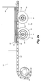
- Fig 1. is a side elevation view of a section of an apparatus for processing panels embodying aspects of the present invention with portions removed.
- Fig 2a is a side elevation view of a section of an apparatus for processing panels as shown in Fig. 1 having a stack of panels positioned at the beginning of a cycle embodying aspects of the present invention with portions removed.
- Fig 2b is a side elevation view of the section of the apparatus of Fig. 2a with the panels and apparatus in a further progression.
- Fig. 2c is a side elevation view of the section of the apparatus of Fig. 2a with the panels and apparatus in a further progression.
- Fig 3 is a side elevation view of a first cam embodying principles of the present invention.
- Fig 4 is a side elevation view of a second cam embodying principles of the present invention.
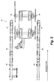
- Fig 5 is a top view of the section of apparatus embodying principles of the present invention.
-
- The present invention, as shown in Figs. 1-5, comprises an
apparatus 10 for reducing the likelihood that the face of a ceiling panel is marred as it is removed from a stack of similar panels. The apparatus provides a pair of synchronized cams working together to lift a portion of a stack of panels as the bottom most panel is being removed from the stack. By supporting the stack of panels as the bottom panel is removed therefrom, the bottom panel can be slid out from under a stack with less chance of damaging the facing of the panel then would arise if the stack was not supported. - Figs 1 and 5 show two different views of a section of the
apparatus 10 of the present apparatus for feeding panels. Some sections of the apparatus have been removed for clarity. The apparatus generally includes a pair oftenoner chains 60 to which are attachedpushers 40 that are spaced at appropriate intervals. Thetenoner chains 60 run below ahopper 50 into which panels are stacked during the manufacture of the panels. Situated generally below the hopper, although other arrangements are also contemplated, arecams apparatus 10 is shown in Fig. 5 with thefirst cams 31 and twosecond cams 34, the present invention encompasses other configurations in which the number of first andsecond cams - The
tenoner chains 60 andcams tenoner chains 60 andcams - In greater detail, as shown in Figs. 2a-2c, the stack of
panels 20 is lifted using acam system 30 while the first orbottom panel 21 is removed using spacedpushers 40. This process is designed to occur under steady state operating conditions with the panels being conveyed to ahopper 50 and stacked between four or five panels high. The panels have decorative images on one side of the panel and are stacked image side up in thehopper 50. The panels are removed from the hopper on a first-in/first-out basis. Evenly spacedpushers 40 attached to a pair oftransport chains 60 remove thepanel 21 from the bottom of thestack 20. Thepushers 40 engage one edge of thebottom panel 21 and slide thepanel 21 out from under thestack 20. To prevent thebottom panel 21 from being scratched when it is slid out from under thisstack 20, the present invention raises the remaining panels using thecams 30. Thepanel stack 20 is raised above thepanel 21 being slid out from under thestack 20. - The
cams 30 which raise the remaining panels each comprise a major lobe and a minor lobe to provide lift at certain intervals in a synchronized manner. The major lobes engage the underside of the panel just above the bottom panel just as the bottom panel begins to slide out from under the stack. As the bottommost panel 21 is slid past the halfway point A of thefirst cam 31, thefirst cam 31 then engages and lifts thepanel 22 residing directly above the bottommost panel 21 being slid out from under thestack 20. When the bottommost panel 21 slides past the halfway point B of thesecond cam 34, thesecond cam 34 also engages and lifts thepanel 22 residing directly above the bottommost panel 21. The duration of the lift is designed to keep thestack 20 elevated until thebottom panel 21 clears the remaining panels in thestack 20. The cam profiles then lower thestack 20 and the process repeats itself. - The
first cam 31 includes a firstmajor lobe 32 and firstminor lobe 33. Likewise thesecond cam 34 includes a secondmajor lobe 35 and a secondminor lobe 36. Each major lobe has a radius that is greater than the minor lobe on the same cam. In the embodiment of the apparatus shown in Figs. 2a-2c, theminor lobes cams major lobe 32 of thefirst cam 31 can comprise between about 180° and about 220° of an angular profile of the circumference of the first cam as illustrated in Fig. 3. The firstminor lobe 33 of thefirst cam 31 can comprise between about 60° and about 100° of an angular profile of the circumference of thefirst cam 31 as illustrated in Fig. 3. - The
second cam 34 also has both a secondmajor lobe 35 and a second minor 36 lobe. The secondmajor lobe 35 of thesecond cam 34 can comprise between about 40° and about 80° of an angular profile of the circumference of thesecond cam 34 as illustrated in Fig. 4. The secondminor lobe 36 of thesecond cam 34 can comprise between about 200° and about 240° of an angular profile of the circumference of thesecond cam 34 as illustrated in Fig. 4. - Furthermore, the first and
second cams transition zones first cam 31 hastransition zones 38 and thesecond cam 34 hastransition zones 37. Thetransition zones transition zones second cams cams - The first and
second cams cams major lobe 32 of thefirst cam 31 would be increased and the angle for themajor lobe 35 of thesecond cam 34 would be decreased. The opposite would be true for intervals spaced at distances of less than about 10 to about 14 inches. - While certain embodiments have been illustrated and described above, it is recognized that variations may be made with respect to disclosed embodiments. Therefore, while the invention has been disclosed in various forms only, it will be obvious to those skilled in the art that many additions, deletions and modifications can be made without departing from the spirit and scope of this invention, and no undue limits should be imposed except as set forth in the following claims.
Claims (15)
- An apparatus for feeding a first panel having a trailing edge from a stack of panels residing above the first panel, the stack of panels having a trailing portion and a trailing edge portion, the apparatus comprising:a pusher engaging the first panel trailing edge;a first cam having a first major lobe and a first minor lobe, wherein the first major lobe engages the trailing edge portion of the stack residing above the first panel as the pusher moves the first panel out from under the stack at a first position; anda second cam having a second major lobe and a second minor lobe, wherein the second major lobe engages the leading edge portion of the stack residing above the first panel as the pusher moves the first panel out from under the stack at a second position.
- The apparatus of claim 1, wherein the first minor lobe and the second minor lobe engage the stack residing above the first panel and lower the stack.
- The apparatus of claim 1, wherein the first cam has a first transition zone and the second cam has a second transition zone and the first transition zone and the second transition zone engage the stack residing above the first panel and then lower the stack.
- The apparatus of claim 1, wherein the first major lobe has a greater angular profile than the profile of the second major lobe.
- The apparatus of claim 1, wherein the first cam is mechanically linked using a timing chain to a tenoner transport chain.
- The apparatus of claim 5, wherein the transport chain sets the first cam in motion to synchronize the engaging of the first major lobe with the trailing edge portion of the stack with the engaging of the pusher with the trailing edge of the first panel.
- The apparatus of claim 1, further comprising a second timing chain mechanically linking the first cam to the second cam for synchronizing a lifting sequence.
- The apparatus of claim 1, wherein the first major diameter comprises about 180° to about 220° of the circumference of the first cam.
- The apparatus of claim 1, wherein the second major diameter comprises about 40° to about 80° of the circumference of the second cam.
- The apparatus of claim 1, wherein the first panel and stack of panels residing above the first panel are housed in a hopper.
- A method for delivering a panel having a trailing edge comprising:pushing a first panel from a stack of panels residing above the first panel, the stack having a trailing edge portion and a leading edge portion;supporting the trailing edge portion of the stack residing above the first panel as the first panel trailing edge is pushed out from under the trailing edge portion of the stack at a first position; andsupporting the leading edge portion of the stack residing above the first panel trailing edge as the first panel is pushed out from under the leading edge portion of the stack at a second position.
- The method of claim 11, wherein the first panel is removed from the stack of panels without substantially marring the panel.
- The method of claim 11, wherein the supporting of the stack residing above the first panel is synchronized with the pushing of the panel.
- The method of claim 11, wherein the first panel is pushed by a pusher which pusher engages the trailing edge of the panel, the trailing edge portion of the stack being supported by a cam as the trailing edge of the panel moves out from under the trailing edge portion of the stack.
- The method of claim 11, wherein the leading edge portion of the stack is supported by a second cam as the trailing edge of the panel moves out from under the leading edge portion of the stack.
Applications Claiming Priority (2)
| Application Number | Priority Date | Filing Date | Title |
|---|---|---|---|
| US35648 | 2001-12-28 | ||
| US10/035,648 US6626633B2 (en) | 2001-12-28 | 2001-12-28 | Apparatus for feeding a panel from a stack |
Publications (3)
| Publication Number | Publication Date |
|---|---|
| EP1323652A2 true EP1323652A2 (en) | 2003-07-02 |
| EP1323652A3 EP1323652A3 (en) | 2003-11-19 |
| EP1323652B1 EP1323652B1 (en) | 2006-05-17 |
Family
ID=21883948
Family Applications (1)
| Application Number | Title | Priority Date | Filing Date |
|---|---|---|---|
| EP02029027A Expired - Lifetime EP1323652B1 (en) | 2001-12-28 | 2002-12-27 | Method and apparatus for feeding a panel from a stack |
Country Status (6)
| Country | Link |
|---|---|
| US (1) | US6626633B2 (en) |
| EP (1) | EP1323652B1 (en) |
| AT (1) | ATE326412T1 (en) |
| CA (1) | CA2415133A1 (en) |
| DE (1) | DE60211458T2 (en) |
| MX (1) | MXPA03000131A (en) |
Families Citing this family (28)
| Publication number | Priority date | Publication date | Assignee | Title |
|---|---|---|---|---|
| US20070283246A1 (en) * | 2004-04-08 | 2007-12-06 | Just System Corporation | Processing Documents In Multiple Markup Representations |
| DK176572B1 (en) * | 2004-10-21 | 2008-09-22 | Gram Equipment As | Apparatus for feeding sticks into an apparatus for inserting sticks into ice-cream bodies |
| US8152004B2 (en) * | 2005-05-05 | 2012-04-10 | Dixie Consumer Products Llc | Dispenser for disposable cutlery and components therefor |
| US8210364B2 (en) | 2005-05-05 | 2012-07-03 | Dixie Consumer Products Llc | Dispenser for disposable cutlery and components therefor |
| US9237815B2 (en) | 2006-11-07 | 2016-01-19 | Dixie Consumer Products Llc | Cutlery dispenser and method of dispensing cutlery |
| EP2096964A2 (en) * | 2006-11-07 | 2009-09-09 | Dixie Consumer Products LLC | Cutlery dispenser and method of dispensing cutlery |
| WO2009042864A2 (en) * | 2007-09-27 | 2009-04-02 | Graphic Packaging International, Inc. | Carton feeder having friction reducing support shaft |
| EP2112110A1 (en) * | 2008-04-25 | 2009-10-28 | Kba-Giori S.A. | Method and system for processing bundles of securities, in particular banknote bundles |
| US8701932B2 (en) | 2008-10-08 | 2014-04-22 | Dixie Consumer Products Llc | Cutlery dispenser trays |
| US8360273B2 (en) | 2008-10-08 | 2013-01-29 | Dixie Consumer Products Llc | Cutlery utensil dispenser |
| US8070013B2 (en) * | 2009-01-06 | 2011-12-06 | Dixie Consumer Products Llc | Cutlery utensil dispensing apparatus and method |
| US9295344B2 (en) | 2010-03-19 | 2016-03-29 | Dixie Consumer Products Llc | Cutlery utensil dispenser |
| EP2579751A4 (en) | 2010-06-08 | 2013-10-23 | Dixie Consumer Products Llc | System and method for holding cutlery together |
| EP2603117B1 (en) | 2010-08-12 | 2018-11-14 | GPCP IP Holdings LLC | Interlocking cutlery and related methods |
| EP2608701B1 (en) | 2010-08-24 | 2018-10-17 | GPCP IP Holdings LLC | Removable strip for packaging cutlery and related methods |
| CA2820650C (en) | 2010-12-10 | 2019-03-12 | Dixie Consumer Products Llc | Dispensing mechanism for utensil dispenser and related methods |
| CA2820552C (en) | 2010-12-10 | 2019-01-08 | Dixie Consumer Products Llc | Screw drive for dispensing cutlery and related methods |
| CA2819646C (en) | 2010-12-14 | 2019-10-01 | Dixie Consumer Products Llc | Belt drive for dispensing cutlery and related methods |
| US9439518B2 (en) | 2011-08-19 | 2016-09-13 | Dixie Consumer Products Llc | Cutlery dispenser |
| US9049948B2 (en) | 2012-01-27 | 2015-06-09 | Us Foods, Inc. | Utensil dispenser |
| US9266646B2 (en) | 2012-09-07 | 2016-02-23 | Dixie Consumer Products Llc | Cutlery utensil dispensing package |
| WO2015013203A1 (en) | 2013-07-25 | 2015-01-29 | Dixie Consumer Products Llc | Cutlery dispenser and related methods |
| US10220997B2 (en) | 2013-07-25 | 2019-03-05 | Gpcp Ip Holdings Llc | Cutlery dispenser and related methods |
| EP3030501B1 (en) | 2013-08-08 | 2018-12-05 | GPCP IP Holdings LLC | Front loading cutlery dispenser |
| US9332861B2 (en) | 2013-08-19 | 2016-05-10 | Dixie Consumer Products Llc | Cutlery dispenser and methods of use |
| AU2014389989B2 (en) | 2014-04-11 | 2019-06-13 | Gpcp Ip Holdings Llc | Forward advancing cutlery dispenser |
| DE102017207004A1 (en) * | 2017-04-26 | 2018-10-31 | Homag Gmbh | Device for separating workpieces |
| CN115180421B (en) * | 2022-07-27 | 2023-11-17 | 上海平臣实业有限公司 | Stacked article separating device |
Citations (3)
| Publication number | Priority date | Publication date | Assignee | Title |
|---|---|---|---|---|
| DE827475C (en) * | 1949-08-18 | 1952-01-10 | Ver Tabaksindustrieeen Mignot | Device for conveying objects in sequence from a storage container |
| GB1040645A (en) * | 1963-06-28 | 1966-09-01 | Leray Jules | Means for feeding empty pallets to loading tables |
| DE4005372A1 (en) * | 1990-02-21 | 1991-08-22 | Protechno Card Gmbh | Data card attaching device for letter - has stamped out retaining flaps in surface of letter sheet released to allow data card insertion |
Family Cites Families (9)
| Publication number | Priority date | Publication date | Assignee | Title |
|---|---|---|---|---|
| US3506258A (en) * | 1967-10-06 | 1970-04-14 | Measurement Research Center In | Document feeding mechanism |
| US4462738A (en) * | 1979-01-22 | 1984-07-31 | M. S. Willett, Inc. | Feed and transfer system |
| US4396336A (en) * | 1981-01-26 | 1983-08-02 | Herman Malamood | Apparatus for feeding lifts of limp sheets |
| US4702660A (en) * | 1985-11-12 | 1987-10-27 | Evana Tool & Engineering Inc. | Method and apparatus for storing and handling trays for workpieces |
| JPS63208431A (en) * | 1986-09-09 | 1988-08-29 | Nitto Seimo Kk | Device for feeding cages to shelf tiers of carriage and the like via separation thereof from stack starting from lowest layer |
| JPH04327426A (en) * | 1991-04-26 | 1992-11-17 | Asahi Chem Ind Co Ltd | Plate separating-loading device |
| JPH06144578A (en) * | 1992-11-10 | 1994-05-24 | Kataoka Mach Co Ltd | Pallet feeding device |
| JP2987061B2 (en) * | 1994-08-19 | 1999-12-06 | オークラ輸送機株式会社 | Picking equipment |
| US5938073A (en) * | 1997-09-08 | 1999-08-17 | Gamemax Corporation | Card stacking and conveyance structure for automatic card vending machines |
-
2001
- 2001-12-28 US US10/035,648 patent/US6626633B2/en not_active Expired - Fee Related
-
2002
- 2002-12-24 CA CA002415133A patent/CA2415133A1/en not_active Abandoned
- 2002-12-27 AT AT02029027T patent/ATE326412T1/en not_active IP Right Cessation
- 2002-12-27 EP EP02029027A patent/EP1323652B1/en not_active Expired - Lifetime
- 2002-12-27 DE DE60211458T patent/DE60211458T2/en not_active Expired - Lifetime
-
2003
- 2003-01-07 MX MXPA03000131A patent/MXPA03000131A/en unknown
Patent Citations (3)
| Publication number | Priority date | Publication date | Assignee | Title |
|---|---|---|---|---|
| DE827475C (en) * | 1949-08-18 | 1952-01-10 | Ver Tabaksindustrieeen Mignot | Device for conveying objects in sequence from a storage container |
| GB1040645A (en) * | 1963-06-28 | 1966-09-01 | Leray Jules | Means for feeding empty pallets to loading tables |
| DE4005372A1 (en) * | 1990-02-21 | 1991-08-22 | Protechno Card Gmbh | Data card attaching device for letter - has stamped out retaining flaps in surface of letter sheet released to allow data card insertion |
Also Published As
| Publication number | Publication date |
|---|---|
| ATE326412T1 (en) | 2006-06-15 |
| US6626633B2 (en) | 2003-09-30 |
| US20030123969A1 (en) | 2003-07-03 |
| DE60211458D1 (en) | 2006-06-22 |
| EP1323652B1 (en) | 2006-05-17 |
| EP1323652A3 (en) | 2003-11-19 |
| DE60211458T2 (en) | 2006-11-30 |
| CA2415133A1 (en) | 2003-06-28 |
| MXPA03000131A (en) | 2005-06-08 |
Similar Documents
| Publication | Publication Date | Title |
|---|---|---|
| US6626633B2 (en) | Apparatus for feeding a panel from a stack | |
| US4838920A (en) | Method of and apparatus for positioning of sheets of glass for curving same | |
| US4273489A (en) | Process and apparatus for forming of set layers from brick blanks | |
| CN106927244B (en) | High-speed transfer robot system of photovoltaic panel | |
| CN106514186A (en) | Automatic steel ring grabbing device and method | |
| CN110498242A (en) | It eats out transportation system | |
| EP0801629B1 (en) | Apparatus and method for removing articles from a stack | |
| US4312440A (en) | Brick setting apparatus | |
| CN210628275U (en) | Supporting mechanism for silicon chips in diffusion process basket | |
| CN219135531U (en) | Automatic tray disassembling device for stacked tray stacks | |
| CN219116532U (en) | Ceramic conveying device | |
| CN114868934B (en) | Intelligent peeling production line and method for mustard tuber heads | |
| CA1120329A (en) | Apparatus to form modules of biscuits and the like products | |
| CN210486512U (en) | Transport conveyor of silicon calcium ancient building tile | |
| CN110867407B (en) | Method for manufacturing comb-shaped bracket of silicon wafer supporting mechanism in diffusion process basket | |
| GB2287685A (en) | Plate transfer apparatus | |
| JPH0754177Y2 (en) | Standing Article Separation Device | |
| JP3690545B2 (en) | Glass tube quantitative transfer device | |
| RU2002692C1 (en) | Device for removal from conveyor, lifting and rearranging of workpieces | |
| JP3484027B2 (en) | Flat plate unloading device | |
| JP2923423B2 (en) | Magazine removal device for semiconductor device storage | |
| JP3435536B2 (en) | Method and apparatus for centering ceramic products | |
| JPH02217787A (en) | Packing device for box pot | |
| CN110752179A (en) | Supporting mechanism for silicon chips in diffusion process basket | |
| CN113955498A (en) | Cold end burst conveyor |
Legal Events
| Date | Code | Title | Description |
|---|---|---|---|
| PUAI | Public reference made under article 153(3) epc to a published international application that has entered the european phase |
Free format text: ORIGINAL CODE: 0009012 |
|
| AK | Designated contracting states |
Designated state(s): AT BE BG CH CY CZ DE DK EE ES FI FR GB GR IE IT LI LU MC NL PT SE SI SK TR |
|
| AX | Request for extension of the european patent |
Extension state: AL LT LV MK RO |
|
| PUAL | Search report despatched |
Free format text: ORIGINAL CODE: 0009013 |
|
| AK | Designated contracting states |
Kind code of ref document: A3 Designated state(s): AT BE BG CH CY CZ DE DK EE ES FI FR GB GR IE IT LI LU MC NL PT SE SI SK TR |
|
| AX | Request for extension of the european patent |
Extension state: AL LT LV MK RO |
|
| 17P | Request for examination filed |
Effective date: 20040503 |
|
| AKX | Designation fees paid |
Designated state(s): AT BE BG CH CY CZ DE DK EE ES FI FR GB GR IE IT LI LU MC NL PT SE SI SK TR |
|
| 17Q | First examination report despatched |
Effective date: 20050216 |
|
| GRAP | Despatch of communication of intention to grant a patent |
Free format text: ORIGINAL CODE: EPIDOSNIGR1 |
|
| GRAS | Grant fee paid |
Free format text: ORIGINAL CODE: EPIDOSNIGR3 |
|
| GRAA | (expected) grant |
Free format text: ORIGINAL CODE: 0009210 |
|
| AK | Designated contracting states |
Kind code of ref document: B1 Designated state(s): AT BE BG CH CY CZ DE DK EE ES FI FR GB GR IE IT LI LU MC NL PT SE SI SK TR |
|
| PG25 | Lapsed in a contracting state [announced via postgrant information from national office to epo] |
Ref country code: IT Free format text: LAPSE BECAUSE OF FAILURE TO SUBMIT A TRANSLATION OF THE DESCRIPTION OR TO PAY THE FEE WITHIN THE PRESCRIBED TIME-LIMIT;WARNING: LAPSES OF ITALIAN PATENTS WITH EFFECTIVE DATE BEFORE 2007 MAY HAVE OCCURRED AT ANY TIME BEFORE 2007. THE CORRECT EFFECTIVE DATE MAY BE DIFFERENT FROM THE ONE RECORDED. Effective date: 20060517 Ref country code: SK Free format text: LAPSE BECAUSE OF FAILURE TO SUBMIT A TRANSLATION OF THE DESCRIPTION OR TO PAY THE FEE WITHIN THE PRESCRIBED TIME-LIMIT Effective date: 20060517 Ref country code: FI Free format text: LAPSE BECAUSE OF FAILURE TO SUBMIT A TRANSLATION OF THE DESCRIPTION OR TO PAY THE FEE WITHIN THE PRESCRIBED TIME-LIMIT Effective date: 20060517 Ref country code: CH Free format text: LAPSE BECAUSE OF FAILURE TO SUBMIT A TRANSLATION OF THE DESCRIPTION OR TO PAY THE FEE WITHIN THE PRESCRIBED TIME-LIMIT Effective date: 20060517 Ref country code: LI Free format text: LAPSE BECAUSE OF FAILURE TO SUBMIT A TRANSLATION OF THE DESCRIPTION OR TO PAY THE FEE WITHIN THE PRESCRIBED TIME-LIMIT Effective date: 20060517 Ref country code: BE Free format text: LAPSE BECAUSE OF FAILURE TO SUBMIT A TRANSLATION OF THE DESCRIPTION OR TO PAY THE FEE WITHIN THE PRESCRIBED TIME-LIMIT Effective date: 20060517 Ref country code: AT Free format text: LAPSE BECAUSE OF FAILURE TO SUBMIT A TRANSLATION OF THE DESCRIPTION OR TO PAY THE FEE WITHIN THE PRESCRIBED TIME-LIMIT Effective date: 20060517 Ref country code: SI Free format text: LAPSE BECAUSE OF FAILURE TO SUBMIT A TRANSLATION OF THE DESCRIPTION OR TO PAY THE FEE WITHIN THE PRESCRIBED TIME-LIMIT Effective date: 20060517 Ref country code: CZ Free format text: LAPSE BECAUSE OF FAILURE TO SUBMIT A TRANSLATION OF THE DESCRIPTION OR TO PAY THE FEE WITHIN THE PRESCRIBED TIME-LIMIT Effective date: 20060517 Ref country code: NL Free format text: LAPSE BECAUSE OF FAILURE TO SUBMIT A TRANSLATION OF THE DESCRIPTION OR TO PAY THE FEE WITHIN THE PRESCRIBED TIME-LIMIT Effective date: 20060517 |
|
| REG | Reference to a national code |
Ref country code: GB Ref legal event code: FG4D |
|
| REG | Reference to a national code |
Ref country code: CH Ref legal event code: EP |
|
| REG | Reference to a national code |
Ref country code: IE Ref legal event code: FG4D |
|
| REF | Corresponds to: |
Ref document number: 60211458 Country of ref document: DE Date of ref document: 20060622 Kind code of ref document: P |
|
| PG25 | Lapsed in a contracting state [announced via postgrant information from national office to epo] |
Ref country code: DK Free format text: LAPSE BECAUSE OF FAILURE TO SUBMIT A TRANSLATION OF THE DESCRIPTION OR TO PAY THE FEE WITHIN THE PRESCRIBED TIME-LIMIT Effective date: 20060817 Ref country code: SE Free format text: LAPSE BECAUSE OF FAILURE TO SUBMIT A TRANSLATION OF THE DESCRIPTION OR TO PAY THE FEE WITHIN THE PRESCRIBED TIME-LIMIT Effective date: 20060817 |
|
| PG25 | Lapsed in a contracting state [announced via postgrant information from national office to epo] |
Ref country code: ES Free format text: LAPSE BECAUSE OF FAILURE TO SUBMIT A TRANSLATION OF THE DESCRIPTION OR TO PAY THE FEE WITHIN THE PRESCRIBED TIME-LIMIT Effective date: 20060828 |
|
| PG25 | Lapsed in a contracting state [announced via postgrant information from national office to epo] |
Ref country code: PT Free format text: LAPSE BECAUSE OF FAILURE TO SUBMIT A TRANSLATION OF THE DESCRIPTION OR TO PAY THE FEE WITHIN THE PRESCRIBED TIME-LIMIT Effective date: 20061017 |
|
| NLV1 | Nl: lapsed or annulled due to failure to fulfill the requirements of art. 29p and 29m of the patents act | ||
| REG | Reference to a national code |
Ref country code: CH Ref legal event code: PL |
|
| PG25 | Lapsed in a contracting state [announced via postgrant information from national office to epo] |
Ref country code: IE Free format text: LAPSE BECAUSE OF NON-PAYMENT OF DUE FEES Effective date: 20061228 |
|
| PG25 | Lapsed in a contracting state [announced via postgrant information from national office to epo] |
Ref country code: MC Free format text: LAPSE BECAUSE OF NON-PAYMENT OF DUE FEES Effective date: 20061231 |
|
| PLBE | No opposition filed within time limit |
Free format text: ORIGINAL CODE: 0009261 |
|
| STAA | Information on the status of an ep patent application or granted ep patent |
Free format text: STATUS: NO OPPOSITION FILED WITHIN TIME LIMIT |
|
| 26N | No opposition filed |
Effective date: 20070220 |
|
| EN | Fr: translation not filed | ||
| GBPC | Gb: european patent ceased through non-payment of renewal fee |
Effective date: 20061227 |
|
| PG25 | Lapsed in a contracting state [announced via postgrant information from national office to epo] |
Ref country code: GB Free format text: LAPSE BECAUSE OF NON-PAYMENT OF DUE FEES Effective date: 20061227 |
|
| PG25 | Lapsed in a contracting state [announced via postgrant information from national office to epo] |
Ref country code: GR Free format text: LAPSE BECAUSE OF FAILURE TO SUBMIT A TRANSLATION OF THE DESCRIPTION OR TO PAY THE FEE WITHIN THE PRESCRIBED TIME-LIMIT Effective date: 20060818 Ref country code: FR Free format text: LAPSE BECAUSE OF FAILURE TO SUBMIT A TRANSLATION OF THE DESCRIPTION OR TO PAY THE FEE WITHIN THE PRESCRIBED TIME-LIMIT Effective date: 20070309 |
|
| PG25 | Lapsed in a contracting state [announced via postgrant information from national office to epo] |
Ref country code: EE Free format text: LAPSE BECAUSE OF FAILURE TO SUBMIT A TRANSLATION OF THE DESCRIPTION OR TO PAY THE FEE WITHIN THE PRESCRIBED TIME-LIMIT Effective date: 20060517 Ref country code: BG Free format text: LAPSE BECAUSE OF FAILURE TO SUBMIT A TRANSLATION OF THE DESCRIPTION OR TO PAY THE FEE WITHIN THE PRESCRIBED TIME-LIMIT Effective date: 20060817 |
|
| PG25 | Lapsed in a contracting state [announced via postgrant information from national office to epo] |
Ref country code: TR Free format text: LAPSE BECAUSE OF FAILURE TO SUBMIT A TRANSLATION OF THE DESCRIPTION OR TO PAY THE FEE WITHIN THE PRESCRIBED TIME-LIMIT Effective date: 20060517 Ref country code: LU Free format text: LAPSE BECAUSE OF NON-PAYMENT OF DUE FEES Effective date: 20061227 |
|
| PG25 | Lapsed in a contracting state [announced via postgrant information from national office to epo] |
Ref country code: CY Free format text: LAPSE BECAUSE OF FAILURE TO SUBMIT A TRANSLATION OF THE DESCRIPTION OR TO PAY THE FEE WITHIN THE PRESCRIBED TIME-LIMIT Effective date: 20060517 Ref country code: FR Free format text: LAPSE BECAUSE OF FAILURE TO SUBMIT A TRANSLATION OF THE DESCRIPTION OR TO PAY THE FEE WITHIN THE PRESCRIBED TIME-LIMIT Effective date: 20060517 |
|
| REG | Reference to a national code |
Ref country code: HK Ref legal event code: WD Ref document number: 1052917 Country of ref document: HK |
|
| PGFP | Annual fee paid to national office [announced via postgrant information from national office to epo] |
Ref country code: DE Payment date: 20111229 Year of fee payment: 10 |
|
| REG | Reference to a national code |
Ref country code: DE Ref legal event code: R119 Ref document number: 60211458 Country of ref document: DE Effective date: 20130702 |
|
| PG25 | Lapsed in a contracting state [announced via postgrant information from national office to epo] |
Ref country code: DE Free format text: LAPSE BECAUSE OF NON-PAYMENT OF DUE FEES Effective date: 20130702 |