EP1323619A2 - Steering apparatus controller for electric power steering apparatus - Google Patents
Steering apparatus controller for electric power steering apparatus Download PDFInfo
- Publication number
- EP1323619A2 EP1323619A2 EP02027842A EP02027842A EP1323619A2 EP 1323619 A2 EP1323619 A2 EP 1323619A2 EP 02027842 A EP02027842 A EP 02027842A EP 02027842 A EP02027842 A EP 02027842A EP 1323619 A2 EP1323619 A2 EP 1323619A2
- Authority
- EP
- European Patent Office
- Prior art keywords
- voltage
- drive voltage
- steering apparatus
- sensor
- motor
- Prior art date
- Legal status (The legal status is an assumption and is not a legal conclusion. Google has not performed a legal analysis and makes no representation as to the accuracy of the status listed.)
- Granted
Links
Images




Classifications
-
- B—PERFORMING OPERATIONS; TRANSPORTING
- B62—LAND VEHICLES FOR TRAVELLING OTHERWISE THAN ON RAILS
- B62D—MOTOR VEHICLES; TRAILERS
- B62D5/00—Power-assisted or power-driven steering
- B62D5/04—Power-assisted or power-driven steering electrical, e.g. using an electric servo-motor connected to, or forming part of, the steering gear
- B62D5/0457—Power-assisted or power-driven steering electrical, e.g. using an electric servo-motor connected to, or forming part of, the steering gear characterised by control features of the drive means as such
- B62D5/0481—Power-assisted or power-driven steering electrical, e.g. using an electric servo-motor connected to, or forming part of, the steering gear characterised by control features of the drive means as such monitoring the steering system, e.g. failures
- B62D5/049—Power-assisted or power-driven steering electrical, e.g. using an electric servo-motor connected to, or forming part of, the steering gear characterised by control features of the drive means as such monitoring the steering system, e.g. failures detecting sensor failures
-
- B—PERFORMING OPERATIONS; TRANSPORTING
- B62—LAND VEHICLES FOR TRAVELLING OTHERWISE THAN ON RAILS
- B62D—MOTOR VEHICLES; TRAILERS
- B62D5/00—Power-assisted or power-driven steering
- B62D5/04—Power-assisted or power-driven steering electrical, e.g. using an electric servo-motor connected to, or forming part of, the steering gear
- B62D5/0457—Power-assisted or power-driven steering electrical, e.g. using an electric servo-motor connected to, or forming part of, the steering gear characterised by control features of the drive means as such
- B62D5/0481—Power-assisted or power-driven steering electrical, e.g. using an electric servo-motor connected to, or forming part of, the steering gear characterised by control features of the drive means as such monitoring the steering system, e.g. failures
- B62D5/0484—Power-assisted or power-driven steering electrical, e.g. using an electric servo-motor connected to, or forming part of, the steering gear characterised by control features of the drive means as such monitoring the steering system, e.g. failures for reaction to failures, e.g. limp home
Definitions
- the present invention relates to a steering apparatus controller for an electric power steering apparatus that applies assist torque to a steering system of a vehicle by a motor.
- a typical electric power steering apparatus uses rotational force of an electric motor to assist steering of a steering wheel.
- an electric motor applies assist torque that corresponds to the actual steering torque to a steering mechanism when a driver steers the steering wheel.
- the electric power steering apparatus includes a steering apparatus controller for controlling the applied voltage (motor drive voltage) to the electric motor.
- the steering apparatus controller has a motor driving device for driving the electric motor and a central processing unit (CPU) for sending command signals to the motor driving device in accordance with the motor drive voltage.
- CPU central processing unit
- the steering apparatus controller computes a motor drive current value required for the electric motor to generate the desired assist torque.
- the steering apparatus controller detects the current (actual current) that actually flows through the electric motor and executes a feedback control to determine the motor drive voltage with reference to the detected value of the actual current.
- the steering apparatus controller increases the motor drive voltage to prevent the assist torque from dropping.
- the feedback control permits the appropriate assist torque to be reliably obtained.
- An amplifier that uses, for example, an operational amplifier, is generally located in the device for detecting the actual current.
- the amplifier amplifies a minute signal sent from the electric motor by a predetermined gain at the operational amplifier and sends the amplified signal to the CPU.
- Power required for the operational amplifier to amplify the minute signal is supplied to the operational amplifier from the power source.
- the gain of the amplifier is maintained at a predetermined value by maintaining the voltage supplied to the operational amplifier, or the sensor drive voltage, at a predetermined level due to the structural feature of the operational amplifier.
- Fig. 6 illustrates the relationship among the steering torque 101, the sensor drive voltage 102, the actual current detection value 103, the motor drive voltage 104, and the actual current value 105, which actually flows through the motor.
- the steering torque 101 is constant with respect to the temporal transition.
- the actual current detection value 103 decreases (t10 to t20) according to the decrease of the gain of the operational amplifier although the steering torque is not changed.
- the voltage Vp is a minimum voltage value required for amplifying the signal with the normal gain at the operational amplifier.
- the steering apparatus controller increases the motor drive voltage 104 to prevent the assist torque from dropping. This increases the actual current value 105.
- the steering torque since the steering torque is not actually changed, the increase of the current value of the actual current causes the electric motor to generate excessive assist torque. Since the excessive assist torque turns the steering wheel excessively, the steering torque, for example, might be applied to the torque sensor, which detects the steering torque, in the direction opposite to the direction that the driver has been applying the steering torque. If the steering torque is applied to the torque sensor in the opposite direction, the steering apparatus controller reverses the rotational direction of the electric motor. If this is repeated, the steering mechanism causes vibration, which deteriorates the steering feeling.
- the objective of the present invention is to provide a steering apparatus controller for an electric power steering apparatus that prevents deterioration of the steering feeling due to vibration of a steering mechanism.
- the present invention provides a steering apparatus controller for an electric power steering apparatus.
- the steering apparatus controller executes a feedback control of an applied voltage to an electric motor.
- the electric motor generates assist torque for assisting steering of a steering wheel.
- the assist torque is based on a detection result of an actual current that flows through the electric motor.
- the steering apparatus controller includes a sensor and a voltage controller. The sensor detects the actual current. When the sensor detects an abnormal decrease of a drive voltage of the sensor, the voltage controller maintains the applied voltage to the electric motor to a drive voltage at a predetermined time before the drive voltage abnormally decreased.
- the present invention also provides a controlling method for an electric power steering apparatus.
- a steering apparatus controller executes a feedback control of an applied voltage to an electric motor.
- the electric motor generates assist torque for assisting steering of a steering wheel based on a detection result of an actual current that flows through the electric motor.
- the detected actual current is detected by a sensor.
- the method includes: detecting an abnormal decrease of a drive voltage of the sensor; and when detecting an abnormal decrease of the drive voltage of the sensor, maintaining the applied drive voltage to the electric motor to a drive voltage at a predetermined time before the drive voltage abnormally decreased.
- a steering apparatus controller according to a preferred embodiment of the present invention will now be described with reference to Figs. 1 to 5, 7, and 8.
- the steering apparatus controller is used for an electric power steering apparatus mounted on an automobile.
- Fig. 1 is a schematic view of the electric power steering apparatus and the steering apparatus controller.
- the electric power steering apparatus includes a steering wheel 1, a steering shaft 2, which is coupled to the steering wheel 1, and a torsion bar 3.
- a torque sensor 4 is attached to the torsion bar 3. When the steering shaft 2 is rotated and force is applied to the torsion bar 3, the torsion bar 3 is twisted according to the strength of the force.
- the torque sensor 4 detects the twist, or the steering torque Ts applied to the steering wheel 1.
- the torque sensor 4 sends a signal representing the steering torque Ts to a central processing unit (CPU) 20.
- CPU central processing unit
- a reduction gear 5 is attached to the steering shaft 2.
- the reduction gear 5 is engaged with a gear 7, which is attached to a rotary shaft of an electric motor M.
- a pinion shaft 8 is attached to the reduction gear 5.
- a pinion 9 is secured to the distal end of the pinion shaft 8.
- the pinion 9 engages with a rack 10.
- the rack 10 and the pinion 9 constitute a rack-and-pinion mechanism 11.
- a tie rod 12 is secured to each end of the rack 10.
- a knuckle 13 is rotatably coupled to one of the distal ends of each tie rod 12.
- Each knuckle 13 is secured to one of front wheels 14.
- One end of each knuckle 13 is rotatably coupled to one of the ends of a cross member 15.
- a vehicle speed sensor 16 is arranged at one of the front wheels 14.
- the vehicle speed sensor 16 sends detection signals corresponding to the rotational speed of the front wheels 14 to the CPU 20.
- the detection signals represent the vehicle speed Vs.
- the CPU 20 determines a drive voltage command value Va to be sent to a motor drive circuit 21 based on signals representing the steering torque Ts and the vehicle speed Vs sent from the torque sensor 4 and the vehicle speed sensor 16.
- the motor drive circuit 21 sends drive current corresponding to the drive voltage command value Va sent from the CPU 20 to the motor M.
- the motor M generates torque for assisting a driver to steer the steering wheel 1.
- the motor drive circuit 21 includes a current sensor 22 (see Fig. 3) for detecting the drive current that actually flows through the motor M.
- a signal representing the actual current detection value Im is sent to the CPU 20.
- the drive voltage command value Va, or the applied voltage (motor drive voltage) to the motor M, is feedback-controlled by the CPU 20 based on the detection result of the actual current detection value Im of the motor M.
- the CPU 20 increases the motor drive voltage to prevent the assist torque from dropping.
- the CPU 20 and the motor drive circuit 21 constitute the steering apparatus controller.
- the functions and operations of the steering apparatus controller will now be described with reference to block diagrams shown in Figs. 2 and 3.
- the CPU 20 executes a program stored in a read only memory (ROM), which is not shown, located in the steering apparatus controller.
- the program may be recorded on a recording medium such as a magnetic disk.
- the CPU 20 receives the steering torque Ts and the vehicle speed Vs sent from the torque sensor 4 and the vehicle speed sensor 16.
- the CPU 20 computes an actual current command value Ia to be sent to the motor M based on the steering torque Ts and the vehicle speed Vs by a current command value calculator 23 and sends the actual current command value Ia to a current controller 24.
- the CPU 20 receives the actual current detection value Im sent from the motor drive circuit 21 and computes the current command value Ib of the normal state based on the present current command value Ia and the actual current detection value Im to generate assist torque appropriate for the steering torque Ts and the vehicle speed Vs.
- the CPU 20 then sends the computed current command value Ib to a pulse width modulation (PWM) calculator 25.
- PWM pulse width modulation
- the CPU 20 stores the current command value Ib in a RAM (not shown) located in the steering apparatus controller.
- the CPU 20 performs a PWM calculation based on the current command value Ib at the PWM calculator 25.
- the CPU 20 sends the calculation result to the motor drive circuit 21 as the drive voltage command value Va.
- the motor M is controlled via the motor drive circuit 21.
- the motor M exerts appropriate assist torque according to the detected steering torque Ts and the vehicle speed Vs.
- the motor drive circuit 21 includes a gate drive circuit 26 and a bridge circuit 27.
- the gate drive circuit 26 receives the drive voltage command value Va sent from the PWM calculator 25 of the CPU 20.
- the bridge circuit 27 includes first to fourth transistors Tr1, Tr2, Tr3, and Tr4, each consisting of MOS-FETs (Field Effect Transistors).
- MOS-FETs Field Effect Transistors
- the first transistor Tr1 and the second transistor Tr2 are serially connected to each other and the third transistor Tr3 and the fourth transistor Tr4 are serially connected to each other. Two sets of serial transistors are connected in parallel.
- a motor power source 28 is connected to the node between the first transistor Tr1 and the third transistor Tr3.
- the node between the second transistor Tr2 and the fourth transistor Tr4 is grounded via a resistor 29.
- the motor M is connected to the bridge circuit 27 between the node of the first and second transistors Tr1, Tr2 and the node of the third and fourth transistors Tr3, Tr4.
- the node between the third transistor Tr3 and the fourth transistor Tr4 is connected to the motor M via a power discontinuing device, which is a motor relay 30.
- the motor relay 30 is connected to the CPU 20 via a relay drive circuit, which is not shown, located in the steering apparatus controller.
- the gate drive circuit 26 is constituted by, for example, a pulse width modulation circuit, a logical circuit, and the like-
- the gate drive circuit 26 supplies voltage to each of the transistors Tr1 to Tr4 in accordance with the drive voltage command value Va sent from the CPU 20 to control the drive current to the motor M, or the rotational direction and the drive torque (rotational angle) of the motor M.
- the gate drive circuit 26 supplies voltage to the gate terminals of the second and third transistors Tr2 and Tr3. Accordingly, current flows to the third transistor Tr3, the motor M, and the second transistor Tr2 in this order causing the motor M to rotate clockwise.
- the gate drive circuit 26 supplies voltage to the gate terminals of the first and fourth transistors Tr1 and Tr4. Accordingly, current flows to the first transistor Tr1, the motor M, and the fourth transistor Tr4 in this direction causing the motor M to rotate counterclockwise.
- the CPU 20 controls the direction and level of current that flows to the motor M to control the rotational direction and the drive torque of the motor M.
- the amount of current that is the same as the current actually flowing through the motor M flows through the resistor 29 while the motor M is rotated by the voltage supply from the gate drive circuit 26.
- the path between the bridge circuit 27 and the motor M may be discontinued by the motor relay 30 to stop the motor M.
- the path is discontinued by the motor relay 30, the counterflow of current to the bridge circuit 27 is prevented from being caused by the counter electromotive force of the motor.
- the current sensor 22 has an amplifier 22a that uses, for example, an operational amplifier for amplifying input signals from terminals connected to both ends of the resistor 29.
- the current sensor 22 amplifies the signals from the terminals with a predetermined gain at the amplifier 22a and sends the amplified signals to the CPU 20 as the actual current detection value Im.
- the current sensor 22 is connected to a sensor power source 31, which is a power source for permitting the amplifier 22a to amplify signals, or driving the current sensor 22.
- the gain of the current sensor 22 is maintained at a predetermined value by keeping the power source voltage (sensor drive voltage Vb) at a predetermined level, or at a reference voltage Vd due to the structural feature of the operational amplifier used in the amplifier 22a.
- the sensor power source 31 has a voltage sensor 31a for detecting the voltage of the sensor power source 31.
- the voltage sensor 31a sends signals concerning the sensor drive voltage Vb to the CPU 20.
- the CPU 20 has an abnormality sensor 32.
- the abnormality sensor 32 and the voltage sensor 31a form abnormality detection means for the sensor drive voltage.
- the CPU 20 compares the sensor drive voltage Vb with the reference voltage Vd. Then, the CPU 20 sends a signal C concerning the comparison result to the current controller 24.
- the CPU 20 executes a control that is different from the feedback control executed in the normal state, in which the sensor drive voltage Vb is greater than or equal to the reference voltage Vd. That is, the CPU 20 controls the level of the applied voltage to the motor M to be maintained at the level before the abnormality occurs and when the drive voltage Vb is normal.
- the CPU 20 replaces the current command value Ib to be sent to the PWM calculator 25 with the current command value Ib, which is stored in the RAM at a predetermined time in the normal state before the abnormality occurs.
- the current command value Ib is maintained constant. This prevents the assist torque from increasing excessively due to the decrease of the gain of the current sensor 22.
- the current controller 24, the PWM calculator 25, and the motor drive circuit 21 constitute a voltage controller.
- the CPU 20 includes an abnormality detection timer (not shown) and a normality detection timer (not shown).
- the abnormality detection timer calculates the time elapsed from when the abnormality of the drive voltage of the current sensor 22 is caused.
- the normality detection timer calculates the time elapsed from when the drive voltage of the current sensor is restored from the abnormal state to the normal state.
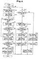
- step S1 the CPU 20 compares the sensor drive voltage Vb with the reference voltage Vd. If it is determined that the sensor drive voltage Vb is less than the reference voltage Vd, the CPU 20 determines it is abnormal and proceeds to step S2.
- step S2 the CPU 20 increments the abnormality detection timer.
- step S3 the CPU 20 clears the normality detection timer and sets the elapsed time to zero.
- step S4 the CPU 20 determines whether an abnormality detection flag is on. If it is determined that the abnormality detection flag is off, the CPU 20 proceeds to step S5.
- step S5 the CPU 20 maintains the level of the motor drive voltage to the level at the predetermined time in the normal state before the abnormality occurs.
- step S6 the CPU 20 compares and determines whether the cumulative time of the abnormality detection timer is greater than a predetermined time ta. If it is determined that the cumulative time is less than or equal to the predetermined time ta, the CPU 20 terminates the routine to return to step S1. On the other hand, if it is determined that the cumulative time is greater than the predetermined time ta, the CPU 20 proceeds to step S7. In step S7, the CPU 20 turns the abnormality detection flag on and stores the result in the RAM.
- step S4 determines that a gradual decrease process of the motor drive voltage has already been performed in the former routine. Thus, the CPU 20 skips steps S5 to S7 and proceeds to step S8. In step S8, the CPU 20 starts the gradual decrease process of the motor drive voltage for this routine. In the gradual decrease process, the current controller 24 computes and sends the current command value Ib to the PWM calculator 25 such that the motor drive voltage is gradually decreased.
- step S9 the CPU 20 determines whether the cumulative time of the abnormality detection timer is greater than a predetermined time tb (ta ⁇ tb). If it is determined that the cumulative time is less than or equal to the predetermined time tb, the CPU 20 terminates the routine to return to step S1. On the other hand, if it is determined that the cumulative time is greater than the predetermined time tb, the CPU 20 proceeds to step S10.
- step S10 the CPU 20 turns off the motor relay 30 and discontinues the path between the motor drive circuit 21 and the motor M.
- step S11 the CPU 20 turns on an abnormality confirmation flag and stores the result in the RAM, and then terminates the control procedure of the motor M.
- step S1 If it is determined that the sensor drive voltage Vb is greater than or equal to the reference voltage Vd in step S1, the CPU 20 determines it is normal and proceeds to step S12.
- step S12 the CPU 20 determines whether the abnormality detection flag is on. If it is determined that the abnormality detection flag is on, the CPU 20 determines that the sensor drive voltage Vb is restored from the abnormal state to the normal state, and proceeds to step S13. In step S13, the CPU 20 increments the normality detection timer.
- step S14 the CPU 20 determines whether the cumulative time of the normality detection timer is greater than a predetermined time tc.
- the predetermined time tc is less than the predetermined time ta (tc ⁇ ta). If it is determined that the cumulative time is greater than the predetermined time tc, the CPU 20 proceeds to step S15.
- step S15 the CPU 20 clears the abnormality detection timer.
- step S16 the CPU 20 clears the normality detection timer.
- step S17 the CPU 20 turns off the abnormality detection flag and stores the result in the RAM.
- step S14 if it is determined that the cumulative time is less than or equal to the predetermined time tc in step S14, the CPU 20 proceeds to step S18 and gradually increases the motor drive voltage.
- the current controller 24 computes and sends the current command value Ib to the PWM calculator 25 such that the motor drive voltage is gradually increased.
- the upper limit of the current command value Ib calculated in this control procedure to gradually increase the motor drive voltage is set to the current command value Ia sent from the current command value calculator 23.
- step S12 If it is determined that the abnormality detection flag is off in step S12, the CPU 20 proceeds to step S19 and clears the abnormality detection timer. In step S20, the CPU 20 stops maintaining the motor drive voltage. In step S21, the CPU 20 executes the normal feedback control.
- Fig. 5 shows the relationship among the steering torque Ts, the sensor drive voltage Vb, the actual current detection value Im, the motor drive voltage, and the current actually flowing through the motor M (actual current value) during the control procedure for maintaining the motor drive voltage.
- the steering torque Ts and the vehicle speed Vs are constant with respect to the temporal transition.
- the motor drive voltage is controlled to be maintained to a value at a predetermined time (for example, time t0) in the normal state before the time t1. Accordingly, the actual current value is maintained to a value at the predetermined time, which prevents the assist torque from excessively increasing above the required amount.
- the motor drive voltage Vx slightly increases during a short time from the time t1 to a time t2 at which the motor drive voltage Vx is maintained to a value at the predetermined time in the normal state by the CPU 20, and the actual current value Ix slightly increases accordingly as shown in Fig. 5.
- the increase of the assist torque is not enough to induce the deterioration of the steering feeling.
- Fig. 7 shows the characteristics of the steering torque Ts and the motor drive voltage Vx during the control procedure of the CPU 20 for gradually decreasing the motor drive voltage Vx.
- Fig. 8 shows the characteristics of the steering torque Ts and the motor drive voltage Vx during the control procedures of the CPU 20 for gradually decreasing and gradually increasing the motor drive voltage Vx.
- the steering torque Ts and the vehicle speed Vs are constant with respect to the temporal transition.
- Fig. 7 shows a state in which the motor drive voltage is decreased to zero before the cumulative time of the abnormal detection timer exceeds the predetermined time tb, or before the motor relay 30 is turned off.
- Fig. 8 shows that by repeating the gradual decrease process of the motor drive voltage, the motor drive voltage Vx gradually decreases during time t7 and time t8.
- the motor drive voltage Vx is gradually increased during time t8 to t9 by repeating the gradual increase process.
- the gradual increase process of the motor drive voltage Vx is repeated until the current command value Ib calculated in the gradual increasing process becomes equal to the current command value Ia.
- the present invention provides the following advantages.
- the voltage of the sensor power source 31 need not be directly detected by the voltage sensor 31a.
- the transistors Tr1 to Tr4 of the bridge circuit 27 need not consist of MOS-FETs. Other switching elements may be use as long as the elements can be used for controlling the rotational direction or drive force of the motor M.
- the motor M need not be a direct current motor.
- a brushless type motor or a linear motor may be used.
- the voltage controlling means may be designed such that in the case, in which the sensor drive voltage Vb is restored from the abnormally decreased state to the normal state while the motor drive voltage is gradually decreased, the motor drive voltage is gradually increased if the normal state is continued for a predetermined time period or more.
- a steering apparatus controller for an electric power steering apparatus which includes an electric motor (M) for generating assist torque for assisting steering of a steering wheel (1) and the steering apparatus controller is designed to execute a feedback control of the applied drive voltage to the electric motor (M) based on the detection result of the actual current that flows through the motor.
- a sensor (22) detects the actual current to produce the detection result.
- a voltage controller maintains the applied voltage to the electric motor (M) at the voltage at a predetermined time before the drive voltage abnormally decreased.
Landscapes
- Engineering & Computer Science (AREA)
- Chemical & Material Sciences (AREA)
- Combustion & Propulsion (AREA)
- Transportation (AREA)
- Mechanical Engineering (AREA)
- Power Steering Mechanism (AREA)
- Steering Control In Accordance With Driving Conditions (AREA)
- Control Of Electric Motors In General (AREA)
Abstract
Description
Claims (5)
- A steering apparatus controller for an electric power steering apparatus, wherein the steering apparatus controller executes a feedback control of an applied voltage to an electric motor (M), which electric motor (M) generates assist torque for assisting steering of a steering wheel (1), said assist torque being based on a detection result of an actual current that flows through the electric motor (M), the steering apparatus controller characterized by:a sensor (22) for detecting the actual current; anda voltage controller (21, 24, 25), wherein, when said sensor (22) detects an abnormal decrease of a drive voltage of the sensor (22), the voltage controller (21, 24, 25) maintains the applied voltage to the electric motor (M) to a drive voltage at a predetermined time before the drive voltage abnormally decreased.
- The steering apparatus controller for an electric power steering apparatus according to claim 1, characterized in that, when the applied voltage to the electric motor (M) is maintained constant for a predetermined time period, the voltage controller gradually decreases the applied voltage.
- The steering apparatus controller for an electric power steering apparatus according to claim 2, characterized in that, when the drive voltage of the sensor (22) is restored from an abnormally decreased state to a normal state while the applied voltage to the electric motor (M) is gradually decreased, the voltage controller gradually increases that applied voltage.
- The steering apparatus controller for an electric power steering apparatus according to any one of claims 1 to 3, characterized in that power is supplied to the electric motor via a power discontinuing device (30).
- A controlling method for an electric power steering apparatus, wherein a steering apparatus controller executes a feedback control of an applied voltage to an electric motor (M), which electric motor (M) generates assist torque for assisting steering of a steering wheel (1), based on a detection result of an actual current that flows through the electric motor (M), said detected actual current being detected by a sensor (22), the method characterized by:detecting an abnormal decrease of a drive voltage of said sensor (22); andwherein, when detecting an abnormal decrease of the drive voltage of the sensor (22), maintaining the applied drive voltage to the electric motor (M) to a drive voltage at a predetermined time before the drive voltage abnormally decreased.
Applications Claiming Priority (2)
| Application Number | Priority Date | Filing Date | Title |
|---|---|---|---|
| JP2001382201 | 2001-12-14 | ||
| JP2001382201A JP3946991B2 (en) | 2001-12-14 | 2001-12-14 | Control device for electric power steering device |
Publications (3)
| Publication Number | Publication Date |
|---|---|
| EP1323619A2 true EP1323619A2 (en) | 2003-07-02 |
| EP1323619A3 EP1323619A3 (en) | 2004-01-02 |
| EP1323619B1 EP1323619B1 (en) | 2005-08-10 |
Family
ID=19187425
Family Applications (1)
| Application Number | Title | Priority Date | Filing Date |
|---|---|---|---|
| EP02027842A Expired - Lifetime EP1323619B1 (en) | 2001-12-14 | 2002-12-12 | Steering apparatus controller for electric power steering apparatus |
Country Status (4)
| Country | Link |
|---|---|
| US (1) | US6795762B2 (en) |
| EP (1) | EP1323619B1 (en) |
| JP (1) | JP3946991B2 (en) |
| DE (1) | DE60205448T2 (en) |
Cited By (1)
| Publication number | Priority date | Publication date | Assignee | Title |
|---|---|---|---|---|
| FR2860481A1 (en) * | 2003-10-07 | 2005-04-08 | Mitsubishi Electric Corp | CONTROL DEVICE FOR MOTOR DRIVE-ASSISTED STEERING |
Families Citing this family (20)
| Publication number | Priority date | Publication date | Assignee | Title |
|---|---|---|---|---|
| JP4334953B2 (en) * | 2003-09-16 | 2009-09-30 | 株式会社日立製作所 | Power steering device |
| JP4352253B2 (en) * | 2004-01-29 | 2009-10-28 | 株式会社デンソー | Vehicle transmission ratio variable steering device |
| JP4517734B2 (en) * | 2004-06-03 | 2010-08-04 | 日本精工株式会社 | Electric power steering device |
| US20060228726A1 (en) | 2005-01-06 | 2006-10-12 | Martin Patrick K | Polypeptides having nucleic acid binding activity and compositions and methods for nucleic acid amplification |
| DE102005044629A1 (en) * | 2005-09-19 | 2007-03-22 | Infineon Technologies Ag | Electric motor controlling device for e.g. motor vehicle, has monitoring unit outputting error signals during malfunction of sensor, and safety unit producing alternative motor control signals for controlling motor in quiescent state |
| JP4352268B2 (en) * | 2005-10-21 | 2009-10-28 | トヨタ自動車株式会社 | Electric power steering device |
| JP2008013146A (en) * | 2006-07-10 | 2008-01-24 | Nsk Ltd | Control device for electric power steering device |
| JP5135819B2 (en) * | 2007-02-19 | 2013-02-06 | 株式会社ジェイテクト | Electric power steering device |
| JP4760850B2 (en) * | 2008-04-07 | 2011-08-31 | 三菱電機株式会社 | Electric power steering device |
| CN102224059B (en) | 2010-02-17 | 2013-03-20 | 日本精工株式会社 | Electric Power Steering |
| US8977436B2 (en) * | 2010-07-27 | 2015-03-10 | Mitsubishi Electric Corporation | Electric power steering system |
| JP5867782B2 (en) * | 2011-11-30 | 2016-02-24 | 株式会社ジェイテクト | Vehicle steering system |
| JP6179098B2 (en) * | 2012-12-25 | 2017-08-16 | 株式会社ジェイテクト | Electric power steering device |
| WO2014147694A1 (en) * | 2013-03-18 | 2014-09-25 | 日本精工株式会社 | Electric power steering device |
| US10077070B2 (en) * | 2014-06-13 | 2018-09-18 | Nsk Ltd. | Power-source voltage diagnostic device of electric power steering apparatus |
| JP6380014B2 (en) * | 2014-11-04 | 2018-08-29 | 株式会社ジェイテクト | Electric power steering device |
| JP6198181B2 (en) * | 2015-11-06 | 2017-09-20 | マツダ株式会社 | Vehicle behavior control device |
| JP6464995B2 (en) * | 2015-11-10 | 2019-02-06 | 株式会社デンソー | Voltage sensor abnormality diagnosis device |
| JP6439658B2 (en) * | 2015-11-10 | 2018-12-19 | 株式会社デンソー | Voltage sensor abnormality diagnosis device |
| US20190079119A1 (en) * | 2016-03-15 | 2019-03-14 | Kabushiki Kaisha Toshiba | Storage battery management device and storage battery management method |
Family Cites Families (13)
| Publication number | Priority date | Publication date | Assignee | Title |
|---|---|---|---|---|
| EP0276005B1 (en) * | 1987-01-23 | 1991-07-17 | Mitsubishi Denki Kabushiki Kaisha | Motor-driven type power steering control device |
| JP2936211B2 (en) * | 1991-07-22 | 1999-08-23 | 自動車機器株式会社 | Current limiting method in electric power steering system |
| JP3525269B2 (en) * | 1995-03-09 | 2004-05-10 | 光洋精工株式会社 | Power steering device |
| WO1998058833A1 (en) * | 1997-06-20 | 1998-12-30 | Mitsubishi Denki Kabushiki Kaisha | Motor driven power steering device |
| JPH11147479A (en) * | 1997-11-18 | 1999-06-02 | Mitsubishi Electric Corp | Electric power steering device |
| JP3663880B2 (en) * | 1998-02-03 | 2005-06-22 | 日本精工株式会社 | Control device for electric power steering device |
| JP2000198456A (en) * | 1998-12-28 | 2000-07-18 | Honda Motor Co Ltd | Electric power steering device |
| JP2001341658A (en) * | 2000-03-29 | 2001-12-11 | Toyoda Mach Works Ltd | Control device for electric power steering device |
| JP3531140B2 (en) * | 2000-04-04 | 2004-05-24 | 本田技研工業株式会社 | Electric power steering device |
| JP3511593B2 (en) * | 2000-11-10 | 2004-03-29 | 三菱電機株式会社 | Electric power steering control device |
| JP4639483B2 (en) * | 2001-02-02 | 2011-02-23 | 日本精工株式会社 | Control device for electric power steering device |
| JP3982739B2 (en) * | 2001-05-08 | 2007-09-26 | 本田技研工業株式会社 | Electric power steering device |
| JP3622956B2 (en) * | 2001-05-11 | 2005-02-23 | 本田技研工業株式会社 | Electric power steering device |
-
2001
- 2001-12-14 JP JP2001382201A patent/JP3946991B2/en not_active Expired - Lifetime
-
2002
- 2002-12-12 US US10/316,912 patent/US6795762B2/en not_active Expired - Fee Related
- 2002-12-12 EP EP02027842A patent/EP1323619B1/en not_active Expired - Lifetime
- 2002-12-12 DE DE60205448T patent/DE60205448T2/en not_active Expired - Lifetime
Cited By (1)
| Publication number | Priority date | Publication date | Assignee | Title |
|---|---|---|---|---|
| FR2860481A1 (en) * | 2003-10-07 | 2005-04-08 | Mitsubishi Electric Corp | CONTROL DEVICE FOR MOTOR DRIVE-ASSISTED STEERING |
Also Published As
| Publication number | Publication date |
|---|---|
| DE60205448T2 (en) | 2006-03-30 |
| JP2003182605A (en) | 2003-07-03 |
| US20030120407A1 (en) | 2003-06-26 |
| JP3946991B2 (en) | 2007-07-18 |
| DE60205448D1 (en) | 2005-09-15 |
| US6795762B2 (en) | 2004-09-21 |
| EP1323619B1 (en) | 2005-08-10 |
| EP1323619A3 (en) | 2004-01-02 |
Similar Documents
| Publication | Publication Date | Title |
|---|---|---|
| EP1323619B1 (en) | Steering apparatus controller for electric power steering apparatus | |
| JP3390333B2 (en) | Electric power steering device | |
| JP3063896B2 (en) | Electric power steering device | |
| JP6512440B2 (en) | Steering support device | |
| EP0686542A1 (en) | Electric power steering control apparatus | |
| JP5067015B2 (en) | Electric power steering device | |
| JP3486749B2 (en) | Electric power steering device | |
| JPH0930431A (en) | Electric power steering device | |
| JP2006143151A (en) | Electric power steering device | |
| JP3560024B2 (en) | Electric power steering device | |
| JP2009113676A (en) | Electric power steering device | |
| JP3328595B2 (en) | Electric power steering device | |
| JP3531250B2 (en) | Control device for electric power steering device | |
| JP2009232569A (en) | Motor drive control device and electric power steering arrangement using the same | |
| JPH11129925A (en) | Electric power steering device | |
| JPH0834359A (en) | Electric power steering device | |
| EP1714852A2 (en) | Electric power steering apparatus | |
| JP3755800B2 (en) | Electric power steering device | |
| JP4612508B2 (en) | Electric power steering device | |
| JP5233215B2 (en) | Electric power steering device | |
| JP2002321631A (en) | Electric power steering device | |
| JP3696422B2 (en) | Electric power steering device | |
| JP2006062616A (en) | Vehicle steering assist device | |
| JP3525414B2 (en) | Electric power steering device | |
| JP3358329B2 (en) | Control device for electric power steering device |
Legal Events
| Date | Code | Title | Description |
|---|---|---|---|
| PUAI | Public reference made under article 153(3) epc to a published international application that has entered the european phase |
Free format text: ORIGINAL CODE: 0009012 |
|
| AK | Designated contracting states |
Designated state(s): AT BE BG CH CY CZ DE DK EE ES FI FR GB GR IE IT LI LU MC NL PT SE SI SK TR |
|
| AX | Request for extension of the european patent |
Extension state: AL LT LV MK RO |
|
| PUAL | Search report despatched |
Free format text: ORIGINAL CODE: 0009013 |
|
| AK | Designated contracting states |
Kind code of ref document: A3 Designated state(s): AT BE BG CH CY CZ DE DK EE ES FI FR GB GR IE IT LI LU MC NL PT SE SI SK TR |
|
| AX | Request for extension of the european patent |
Extension state: AL LT LV MK RO |
|
| 17P | Request for examination filed |
Effective date: 20040628 |
|
| AKX | Designation fees paid |
Designated state(s): DE FR GB |
|
| 17Q | First examination report despatched |
Effective date: 20040823 |
|
| GRAP | Despatch of communication of intention to grant a patent |
Free format text: ORIGINAL CODE: EPIDOSNIGR1 |
|
| GRAS | Grant fee paid |
Free format text: ORIGINAL CODE: EPIDOSNIGR3 |
|
| GRAA | (expected) grant |
Free format text: ORIGINAL CODE: 0009210 |
|
| AK | Designated contracting states |
Kind code of ref document: B1 Designated state(s): DE FR GB |
|
| REG | Reference to a national code |
Ref country code: GB Ref legal event code: FG4D |
|
| REF | Corresponds to: |
Ref document number: 60205448 Country of ref document: DE Date of ref document: 20050915 Kind code of ref document: P |
|
| ET | Fr: translation filed | ||
| PLBE | No opposition filed within time limit |
Free format text: ORIGINAL CODE: 0009261 |
|
| STAA | Information on the status of an ep patent application or granted ep patent |
Free format text: STATUS: NO OPPOSITION FILED WITHIN TIME LIMIT |
|
| 26N | No opposition filed |
Effective date: 20060511 |
|
| PGFP | Annual fee paid to national office [announced via postgrant information from national office to epo] |
Ref country code: GB Payment date: 20071212 Year of fee payment: 6 |
|
| GBPC | Gb: european patent ceased through non-payment of renewal fee |
Effective date: 20081212 |
|
| PG25 | Lapsed in a contracting state [announced via postgrant information from national office to epo] |
Ref country code: GB Free format text: LAPSE BECAUSE OF NON-PAYMENT OF DUE FEES Effective date: 20081212 |
|
| REG | Reference to a national code |
Ref country code: FR Ref legal event code: PLFP Year of fee payment: 14 |
|
| PGFP | Annual fee paid to national office [announced via postgrant information from national office to epo] |
Ref country code: DE Payment date: 20151208 Year of fee payment: 14 |
|
| PGFP | Annual fee paid to national office [announced via postgrant information from national office to epo] |
Ref country code: FR Payment date: 20151110 Year of fee payment: 14 |
|
| REG | Reference to a national code |
Ref country code: DE Ref legal event code: R119 Ref document number: 60205448 Country of ref document: DE |
|
| REG | Reference to a national code |
Ref country code: FR Ref legal event code: ST Effective date: 20170831 |
|
| PG25 | Lapsed in a contracting state [announced via postgrant information from national office to epo] |
Ref country code: FR Free format text: LAPSE BECAUSE OF NON-PAYMENT OF DUE FEES Effective date: 20170102 |
|
| PG25 | Lapsed in a contracting state [announced via postgrant information from national office to epo] |
Ref country code: DE Free format text: LAPSE BECAUSE OF NON-PAYMENT OF DUE FEES Effective date: 20170701 |