EP1323335B1 - Electrical heater with thermistor - Google Patents
Electrical heater with thermistor Download PDFInfo
- Publication number
- EP1323335B1 EP1323335B1 EP01977255A EP01977255A EP1323335B1 EP 1323335 B1 EP1323335 B1 EP 1323335B1 EP 01977255 A EP01977255 A EP 01977255A EP 01977255 A EP01977255 A EP 01977255A EP 1323335 B1 EP1323335 B1 EP 1323335B1
- Authority
- EP
- European Patent Office
- Prior art keywords
- electrodes
- heater
- substrate
- electrode
- portions
- Prior art date
- Legal status (The legal status is an assumption and is not a legal conclusion. Google has not performed a legal analysis and makes no representation as to the accuracy of the status listed.)
- Expired - Lifetime
Links
Images
Classifications
-
- H—ELECTRICITY
- H05—ELECTRIC TECHNIQUES NOT OTHERWISE PROVIDED FOR
- H05B—ELECTRIC HEATING; ELECTRIC LIGHT SOURCES NOT OTHERWISE PROVIDED FOR; CIRCUIT ARRANGEMENTS FOR ELECTRIC LIGHT SOURCES, IN GENERAL
- H05B3/00—Ohmic-resistance heating
- H05B3/20—Heating elements having extended surface area substantially in a two-dimensional [2D] plane, e.g. plate-heater
- H05B3/34—Heating elements having extended surface area substantially in a two-dimensional [2D] plane, e.g. plate-heater flexible, e.g. heating nets or webs
- H05B3/342—Heating elements having extended surface area substantially in a two-dimensional [2D] plane, e.g. plate-heater flexible, e.g. heating nets or webs heaters used in textiles
-
- H—ELECTRICITY
- H05—ELECTRIC TECHNIQUES NOT OTHERWISE PROVIDED FOR
- H05B—ELECTRIC HEATING; ELECTRIC LIGHT SOURCES NOT OTHERWISE PROVIDED FOR; CIRCUIT ARRANGEMENTS FOR ELECTRIC LIGHT SOURCES, IN GENERAL
- H05B3/00—Ohmic-resistance heating
- H05B3/20—Heating elements having extended surface area substantially in a two-dimensional [2D] plane, e.g. plate-heater
-
- H—ELECTRICITY
- H05—ELECTRIC TECHNIQUES NOT OTHERWISE PROVIDED FOR
- H05B—ELECTRIC HEATING; ELECTRIC LIGHT SOURCES NOT OTHERWISE PROVIDED FOR; CIRCUIT ARRANGEMENTS FOR ELECTRIC LIGHT SOURCES, IN GENERAL
- H05B3/00—Ohmic-resistance heating
- H05B3/20—Heating elements having extended surface area substantially in a two-dimensional [2D] plane, e.g. plate-heater
- H05B3/22—Heating elements having extended surface area substantially in a two-dimensional [2D] plane, e.g. plate-heater non-flexible
- H05B3/26—Heating elements having extended surface area substantially in a two-dimensional [2D] plane, e.g. plate-heater non-flexible heating conductor mounted on insulating base
-
- H—ELECTRICITY
- H05—ELECTRIC TECHNIQUES NOT OTHERWISE PROVIDED FOR
- H05B—ELECTRIC HEATING; ELECTRIC LIGHT SOURCES NOT OTHERWISE PROVIDED FOR; CIRCUIT ARRANGEMENTS FOR ELECTRIC LIGHT SOURCES, IN GENERAL
- H05B3/00—Ohmic-resistance heating
- H05B3/20—Heating elements having extended surface area substantially in a two-dimensional [2D] plane, e.g. plate-heater
- H05B3/34—Heating elements having extended surface area substantially in a two-dimensional [2D] plane, e.g. plate-heater flexible, e.g. heating nets or webs
- H05B3/342—Heating elements having extended surface area substantially in a two-dimensional [2D] plane, e.g. plate-heater flexible, e.g. heating nets or webs heaters used in textiles
- H05B3/345—Heating elements having extended surface area substantially in a two-dimensional [2D] plane, e.g. plate-heater flexible, e.g. heating nets or webs heaters used in textiles knitted fabrics
-
- H—ELECTRICITY
- H05—ELECTRIC TECHNIQUES NOT OTHERWISE PROVIDED FOR
- H05B—ELECTRIC HEATING; ELECTRIC LIGHT SOURCES NOT OTHERWISE PROVIDED FOR; CIRCUIT ARRANGEMENTS FOR ELECTRIC LIGHT SOURCES, IN GENERAL
- H05B3/00—Ohmic-resistance heating
- H05B3/20—Heating elements having extended surface area substantially in a two-dimensional [2D] plane, e.g. plate-heater
- H05B3/34—Heating elements having extended surface area substantially in a two-dimensional [2D] plane, e.g. plate-heater flexible, e.g. heating nets or webs
- H05B3/342—Heating elements having extended surface area substantially in a two-dimensional [2D] plane, e.g. plate-heater flexible, e.g. heating nets or webs heaters used in textiles
- H05B3/347—Heating elements having extended surface area substantially in a two-dimensional [2D] plane, e.g. plate-heater flexible, e.g. heating nets or webs heaters used in textiles woven fabrics
-
- H—ELECTRICITY
- H05—ELECTRIC TECHNIQUES NOT OTHERWISE PROVIDED FOR
- H05B—ELECTRIC HEATING; ELECTRIC LIGHT SOURCES NOT OTHERWISE PROVIDED FOR; CIRCUIT ARRANGEMENTS FOR ELECTRIC LIGHT SOURCES, IN GENERAL
- H05B2203/00—Aspects relating to Ohmic resistive heating covered by group H05B3/00
- H05B2203/002—Heaters using a particular layout for the resistive material or resistive elements
- H05B2203/003—Heaters using a particular layout for the resistive material or resistive elements using serpentine layout
-
- H—ELECTRICITY
- H05—ELECTRIC TECHNIQUES NOT OTHERWISE PROVIDED FOR
- H05B—ELECTRIC HEATING; ELECTRIC LIGHT SOURCES NOT OTHERWISE PROVIDED FOR; CIRCUIT ARRANGEMENTS FOR ELECTRIC LIGHT SOURCES, IN GENERAL
- H05B2203/00—Aspects relating to Ohmic resistive heating covered by group H05B3/00
- H05B2203/002—Heaters using a particular layout for the resistive material or resistive elements
- H05B2203/005—Heaters using a particular layout for the resistive material or resistive elements using multiple resistive elements or resistive zones isolated from each other
-
- H—ELECTRICITY
- H05—ELECTRIC TECHNIQUES NOT OTHERWISE PROVIDED FOR
- H05B—ELECTRIC HEATING; ELECTRIC LIGHT SOURCES NOT OTHERWISE PROVIDED FOR; CIRCUIT ARRANGEMENTS FOR ELECTRIC LIGHT SOURCES, IN GENERAL
- H05B2203/00—Aspects relating to Ohmic resistive heating covered by group H05B3/00
- H05B2203/002—Heaters using a particular layout for the resistive material or resistive elements
- H05B2203/006—Heaters using a particular layout for the resistive material or resistive elements using interdigitated electrodes
-
- H—ELECTRICITY
- H05—ELECTRIC TECHNIQUES NOT OTHERWISE PROVIDED FOR
- H05B—ELECTRIC HEATING; ELECTRIC LIGHT SOURCES NOT OTHERWISE PROVIDED FOR; CIRCUIT ARRANGEMENTS FOR ELECTRIC LIGHT SOURCES, IN GENERAL
- H05B2203/00—Aspects relating to Ohmic resistive heating covered by group H05B3/00
- H05B2203/013—Heaters using resistive films or coatings
-
- H—ELECTRICITY
- H05—ELECTRIC TECHNIQUES NOT OTHERWISE PROVIDED FOR
- H05B—ELECTRIC HEATING; ELECTRIC LIGHT SOURCES NOT OTHERWISE PROVIDED FOR; CIRCUIT ARRANGEMENTS FOR ELECTRIC LIGHT SOURCES, IN GENERAL
- H05B2203/00—Aspects relating to Ohmic resistive heating covered by group H05B3/00
- H05B2203/017—Manufacturing methods or apparatus for heaters
-
- H—ELECTRICITY
- H05—ELECTRIC TECHNIQUES NOT OTHERWISE PROVIDED FOR
- H05B—ELECTRIC HEATING; ELECTRIC LIGHT SOURCES NOT OTHERWISE PROVIDED FOR; CIRCUIT ARRANGEMENTS FOR ELECTRIC LIGHT SOURCES, IN GENERAL
- H05B2203/00—Aspects relating to Ohmic resistive heating covered by group H05B3/00
- H05B2203/029—Heaters specially adapted for seat warmers
Definitions
- the invention relates to an electrical heater according to the preamble of claim 1.
- An electrical heater of this type is known from WO-A-0043225.
- the invention relates to thermistor controlled heaters, for example those having a positive temperature coefficient material, as set forth in claim 1.
- An object of the present invention is to provide in some embodiments thereof novel electrical heaters that overcome problems in and improve upon the prior art.
- Another object of the invention is to provide in some embodiments thereof novel electrical heaters that are economical and reliable.
- a further object of the invention is to provide in some embodiments thereof novel electrical heaters having the capacity for providing more uniformly heated surfaces.
- Another object of the invention is to provide in some embodiments thereof novel electrical heaters having electrodes with opposite end portions located at a common termination zone, for example at a common corner of the heater or along the same side thereof.
- Another object of the invention is to provide in some embodiments thereof novel electrical heaters formed on a single substrate.
- a further object of the invention is to provide in some embodiments thereof novel electrical heaters having multiple temperature configurations or settings.
- a further object of the invention is to provide in some embodiments thereof novel electrical heaters having multiple temperature configurations or settings without complex or costly electrical controls.
- Yet another object of the invention is to provide in some embodiments thereof novel positive temperature coefficient electrical heaters having multiple temperature settings controlled by a switch.
- Another object of the invention is to provide in some embodiments thereof novel electrical heaters suitable for use in seat heating applications.
- a more particular object of the invention is to provide in some embodiments thereof novel electrical heaters comprising first and second electrodes disposed on a substrate in spaced apart relation, adjacent portions of the first and second electrodes having interdigitated electrode portions protruding therefrom, other adjacent portions of the first and second electrodes devoid of interdigitated electrode portions, a thermistor material electrically interconnecting the first and second electrodes, a summation of electrical paths along the first and second electrodes from corresponding electrical power application end portions thereof to adjacent portions of the first and second electrodes is substantially the same.
- Another more particular object of the invention is to provide in some embodiments thereof novel electrical heaters comprising first and second electrodes disposed on a substrate in spaced apart relation, the first and second electrodes each having opposite end portions located at a common termination zone on the substrate, adjacent portions of the first and second electrodes having interdigitated electrode portions protruding therefrom, a thermistor material electrically interconnecting the first and second electrodes.
- a further more particular object of the invention is to provide in some embodiments thereof novel electrical heaters comprising a plurality of first, second and third electrodes disposed on a substrate in spaced apart relation, the second electrode located between the first and third electrodes, the first, second and third electrodes each having opposite end portions located at a common termination zone of the substrate, a thermistor material electrically interconnecting the first, second and third electrodes.
- Yet another more particular object of the invention is to provide in some embodiments thereof novel electrical heaters comprising first and second electrodes disposed on a substrate in spaced apart relation, a spacing between some adjacent portions of the first and second electrodes is different than a spacing between other adjacent portions of the first and second electrodes, a thermistor material electrically interconnecting the first and second electrodes, a summation of electrical paths along the first and second electrodes from corresponding end portions thereof where electrical power is applied to adjacent portions of the first and second electrodes is substantially the same.
- the electrical heater comprises generally a plurality of at least two, and in the exemplary embodiment of FIG. 1 three, electrodes disposed on a substrate in spaced apart relation.
- the electrodes are interconnected by a thermistor material.
- the substrate is an electrically insulating, or dielectric, material onto which silver or other conductive electrodes are disposed, for example in a screen printing process.
- the thermistor material is a positive temperature coefficient material disposed over the electrodes.
- the substrate is a fabric saturated or coated with a positive temperature coefficient material upon which the plurality of electrodes are formed or deposited or otherwise disposed so that the positive temperature coefficient material interconnects the electrodes.
- a substrate 2 is coated with a thermistor material 4 having first, second and third electrodes 10, 20 and 30 disposed thereon in spaced apart relation.
- the plurality of electrodes each have one or more corresponding electrode portions adjacent to electrode portions of one or more of the other electrodes.
- the thermistor material 4 provides an electrical connection between the spaced apart electrodes, and particularly the adjacent electrode portions thereof and produces heat according to its particular characteristics when voltage is applied to the electrodes.
- the electrodes are also a source of heat, narrower electrodes producing more heat than wider electrodes, but it is generally more efficient to produce heat with the thermistor material rather than with the electrodes.
- the electrodes are thus configured accordingly.
- the electrodes arc configured geometrically to dissipate about the same amount of heat as the thermistor material, thereby providing relatively uniform heating. In other embodiments, however, the electrodes may be configured to produce more or less heat than the thermistor material, depending on the desired heating performance.
- electrodes 10, 20 and 30 are arranged in a generally rectangular, serpentine pattern, and the adjacent electrode portions thereof are predominately linear and parallel.
- the first, second and third electrodes 10, 20 and 30 are substantially continuous strips arranged side by side, with the second electrode 20 disposed between the first and third electrodes 10 and 30. Adjacent portions of the first, second and third electrodes are arranged in a nested serpentine pattern.
- the adjacent electrode portions may be curvilinear and the spacing therebetween may vary along the length of the electrodes.
- the electrode 40 has a curved portion 42 wherein a spacing between the curved portion 42 and another adjacent electrode 50 varies.
- the electrodes each comprise corresponding opposite electrode end portions, preferably located at a common termination zone of the substrate, for example along a common side or at the same corner of the substrate, to facilitate connection to a power supply.
- the first electrode 10 has corresponding opposite end portion 12 and 14
- the second electrode 20 has corresponding opposite end portions 22 and 24
- the third electrode 30 has corresponding opposite end portions 32 and 34.
- the opposite end portions of the electrodes are located on the same end or side of the substrate.
- Electrical power for example from a voltage source, is applied at one of the end portions of at least two of the electrodes to produce heat, as discussed more fully below.
- the electrical power is preferably applied through electrical terminals connected to corresponding voltage application end portions of the electrodes, for example by a switch.
- each electrode and preferably both end portions thereof, are coupled to corresponding electrical terminals, which are also preferably fastened to the substrate at the common termination zone, so that power may be applied to either end portion of the electrode, for example by reconfiguring the switch, depending upon the desired heating configuration.
- Each of the electrical terminals may, for example, be in the form of a stamped metal member having an electrical connector blade and an eyelet or a grommet or a staple or some other structure electrically connectable to the corresponding electrode.
- the electrical terminal comprises a blade 60 fastened to the substrate 2 and electrically coupled to the first electrode 10 by a conducting member 62 extending through the substrate 2 and through the electrode 10 and is fastened thereto by an end portion 63.
- a conducting member 62 extending through the substrate 2 and through the electrode 10 and is fastened thereto by an end portion 63.
- the terminals may also be soldered to the electrodes.
- the electrical heater of FIG. 1 may be configured for operation at different temperatures by appropriate application of electrical power to the end portions of two or more of the electrodes.
- an exemplary switch 70 permits selective application of electrical power to one or the other of the end portions of two or more of the electrodes.
- FIG. 2 is a voltage Connection Table for the multiple temperature settings or configurations of the exemplary three electrode heater of FIG. 1.
- a positive voltage V1+ is applied to the first end portion 12 of the first electrode and a negative voltage V1- (preferably having the same magnitude as the voltage V1+) is applied to the end second portion 34 of the third electrode.
- the heat produced is generally along serpentine path of the first and third electrodes 10 and 30 and in the thermistor material therebetween.
- a summation of electrical paths along the first and third electrodes from the corresponding end portions 12 and 34 thereof, where the voltages V1+ and V1- are applied, to adjacent portions along the electrodes is substantially the same.
- the voltage across the first and third electrodes 10 and 30 is approximately the same anywhere between the opposite ends thereof.
- the heat produced or generated by the thermistor material interconnecting the first and third electrodes is substantially the same along the serpentine path between the opposite end portions thereof, provided that the spacing therebetween is the same and that the voltage across the electrodes remains constant along the electrodes, as illustrated in FIG. 1.
- a positive voltage V1+ is applied to the first end portion 12 of the first electrode 10 and a negative voltage V2- is applied to the second end portion 24 of the second electrode 20.
- the heat produced is generally along serpentine path of the first and second electrodes 10 and 20 and in the thermistor material therebetween.
- a positive voltage V2+ is applied to the first end portion 22 of the second electrode, and negative voltages V1- and V3- are applied to the second end portions 34 and 14 of the third and first electrodes, respectively.
- Heat is thus generated by the thermistor material between the first, second and third electrodes and by the electrodes themselves.
- the voltages applied to the first, second and third electrodes 10, 20 and 30 of FIG. 1 to obtain the low, medium and high temperature settings may be controlled simply and reliably with the switch 70, without the requirement of costly electronic controls, for example circuitry that controls power supplied to the electrodes by varying voltage and/or current.
- the switch 70 is a multi-pole, multi-position switch, for example a TPTT switch, which has three poles and three switch positions.
- the exemplary multi-pole, multi-position switch permits selection of the particular electrodes and the particular end portions thereof to which the voltages arc applied, without the requirement of costly electronic controls.
- the number of switch positions and poles required thereof are dependent on the number of electrodes and temperature settings desired. For example, a two temperature setting heater may be controlled with a DPDT switch, that is, one having two poles and two positions.
- the heaters of the present invention may also be controlled by microprocessor based controllers, for example those in processor based automotive electrical systems.
- DC voltages supplied from an automotive electrical system are applied to the electrodes.
- the applied voltages preferably have substantially equal magnitudes.
- the indicated polaritie.s of the voltages may be reversed.
- the intermediate electrodes may be desirable for the intermediate electrodes to have a greater width than the outer electrodes.
- the second electrode 20 is wider than the first and third electrodes 10 and 30. This configuration allows the intermediate second electrode 20 to better source current to or sink current from (depending on the voltage polarities) both the first and third electrodes when the heater is operating in the High Setting indicated in the voltage Connection Table of PIG. 2.
- the spacing between electrodes 40 and electrodes 50 and 52 varies along the lengths thereof. Generally, the smaller the spacing between electrodes, the more heat that is generated by the thermistor material therebetween when voltage is applied to the electrodes. Thus varying the spacing between adjacent portions of the electrodes on the substrate permits controlling the amount of heat produced on the substrate, particularly that produced by the thermistor material disposed therebetween.
- Differing amounts of heat may also be generated by providing interdigitated electrode portions protruding from adjacent portions of the electrodes, thus forming areas or zones on the substrate producing more or less heat, depending on the location and density of the interdigitated portions.
- adjacent electrode portions 40 and 52 include a plurality of interdigitated electrode portions 44 and 53 (only some of which are identified with numerals) protruding therefrom.
- the electrodes are configured so that a summation of electrical paths along adjacent electrodes, from the corresponding voltage application end portions thereof, to adjacent portions along the interdigitated electrode portions is substantially the same, thus providing substantially the same voltage across the adjacent interdigitated electrode portions along the path of the electrodes.
- a seat heater for example the exemplary multi-temperature seat heater of FIG.1, having electrodes with variable spacing and/or interdigitated electrode portions, illustrated generally FIG 4.
Landscapes
- Engineering & Computer Science (AREA)
- Textile Engineering (AREA)
- Resistance Heating (AREA)
- Surface Heating Bodies (AREA)
- Control Of Resistance Heating (AREA)
Abstract
Description
- The invention relates to an electrical heater according to the preamble of claim 1. An electrical heater of this type is known from WO-A-0043225.
- More particularly, the invention relates to thermistor controlled heaters, for example those having a positive temperature coefficient material, as set forth in claim 1.
- Electrical heaters having a thermistor layer interconnecting electrodes disposed on a dielectric material are known generally, as disclosed for example in U.S. Patent No. 4,857,71 1 entitled "Positive Temperature Coefficient Heater" and in U.S. Patent No. 4,931,627 entitled "Positive Temperature Coefficient Heater With Distributed Heating Capability", both of which are assigned commonly with the present application.
- An object of the present invention is to provide in some embodiments thereof novel electrical heaters that overcome problems in and improve upon the prior art.
- Another object of the invention is to provide in some embodiments thereof novel electrical heaters that are economical and reliable.
- A further object of the invention is to provide in some embodiments thereof novel electrical heaters having the capacity for providing more uniformly heated surfaces.
- It is also an object of the invention to provide in some embodiments thereof novel electrical heaters having zones with more or less heat.
- Another object of the invention is to provide in some embodiments thereof novel electrical heaters having electrodes with opposite end portions located at a common termination zone, for example at a common corner of the heater or along the same side thereof.
- Another object of the invention is to provide in some embodiments thereof novel electrical heaters formed on a single substrate.
- A further object of the invention is to provide in some embodiments thereof novel electrical heaters having multiple temperature configurations or settings.
- A further object of the invention is to provide in some embodiments thereof novel electrical heaters having multiple temperature configurations or settings without complex or costly electrical controls.
- Yet another object of the invention is to provide in some embodiments thereof novel positive temperature coefficient electrical heaters having multiple temperature settings controlled by a switch.
- Another object of the invention is to provide in some embodiments thereof novel electrical heaters suitable for use in seat heating applications.
- A more particular object of the invention is to provide in some embodiments thereof novel electrical heaters comprising first and second electrodes disposed on a substrate in spaced apart relation, adjacent portions of the first and second electrodes having interdigitated electrode portions protruding therefrom, other adjacent portions of the first and second electrodes devoid of interdigitated electrode portions, a thermistor material electrically interconnecting the first and second electrodes, a summation of electrical paths along the first and second electrodes from corresponding electrical power application end portions thereof to adjacent portions of the first and second electrodes is substantially the same.
- Another more particular object of the invention is to provide in some embodiments thereof novel electrical heaters comprising first and second electrodes disposed on a substrate in spaced apart relation, the first and second electrodes each having opposite end portions located at a common termination zone on the substrate, adjacent portions of the first and second electrodes having interdigitated electrode portions protruding therefrom, a thermistor material electrically interconnecting the first and second electrodes.
- A further more particular object of the invention is to provide in some embodiments thereof novel electrical heaters comprising a plurality of first, second and third electrodes disposed on a substrate in spaced apart relation, the second electrode located between the first and third electrodes, the first, second and third electrodes each having opposite end portions located at a common termination zone of the substrate, a thermistor material electrically interconnecting the first, second and third electrodes.
- Yet another more particular object of the invention is to provide in some embodiments thereof novel electrical heaters comprising first and second electrodes disposed on a substrate in spaced apart relation, a spacing between some adjacent portions of the first and second electrodes is different than a spacing between other adjacent portions of the first and second electrodes, a thermistor material electrically interconnecting the first and second electrodes, a summation of electrical paths along the first and second electrodes from corresponding end portions thereof where electrical power is applied to adjacent portions of the first and second electrodes is substantially the same.
- These and other objects, aspects, features and advantages of the present invention will become more fully apparent upon careful consideration of the following Detailed Description of the Invention and the accompanying Drawings, which may be disproportionate for ease of understanding, wherein like structure and steps are referenced generally by corresponding numerals and indicators.
-
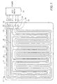
- FIG. 1 is an exemplary electrical heater and control switch according to an exemplary embodiment of the present invention.
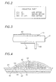
- FIG. 2 is a multiple temperature setting connection table for the exemplary heater of FIG. 1.
- FIG. 3 is an electrical terminal coupled to a substrate and an electrode formed thereon.
- FIG. 4 is a portion of an electrical heater having variable spacing between adjacent electrode portions and interdigitated portions extending therefrom.
- In the present invention, the electrical heater comprises generally a plurality of at least two, and in the exemplary embodiment of FIG. 1 three, electrodes disposed on a substrate in spaced apart relation. The electrodes are interconnected by a thermistor material.
- In one embodiment the substrate is an electrically insulating, or dielectric, material onto which silver or other conductive electrodes are disposed, for example in a screen printing process. In one exemplary embodiment, the thermistor material is a positive temperature coefficient material disposed over the electrodes.
- These and other materials suitable for use as the substrate, electrodes and thermistor material in the present invention are known to those having ordinary skill in the art, as disclosed, for example, in the previously referenced U.S. Patent No. 4,857,711 entitled "Positive Temperature Coefficient Heater" and in U.S. Patent No. 4,931,627 entitled "Positive Temperature Coefficient Heater With Distributed Heating Capability".
- In another embodiment particularly suitable for use in seat heater and related applications, the substrate is a fabric saturated or coated with a positive temperature coefficient material upon which the plurality of electrodes are formed or deposited or otherwise disposed so that the positive temperature coefficient material interconnects the electrodes.
- In the exemplary embodiment of FIG. 1, a
substrate 2 is coated with athermistor material 4 having first, second andthird electrodes - The
thermistor material 4 provides an electrical connection between the spaced apart electrodes, and particularly the adjacent electrode portions thereof and produces heat according to its particular characteristics when voltage is applied to the electrodes. - The electrodes are also a source of heat, narrower electrodes producing more heat than wider electrodes, but it is generally more efficient to produce heat with the thermistor material rather than with the electrodes. The electrodes are thus configured accordingly.
- In some embodiments, the electrodes arc configured geometrically to dissipate about the same amount of heat as the thermistor material, thereby providing relatively uniform heating. In other embodiments, however, the electrodes may be configured to produce more or less heat than the thermistor material, depending on the desired heating performance.
- In the exemplary embodiment,
electrodes - In the exemplary embodiment of FIG. 1, the first, second and
third electrodes second electrode 20 disposed between the first andthird electrodes - In other embodiments, however, the adjacent electrode portions may be curvilinear and the spacing therebetween may vary along the length of the electrodes. In FIG. 4, for example, the
electrode 40 has acurved portion 42 wherein a spacing between thecurved portion 42 and anotheradjacent electrode 50 varies. - The electrodes each comprise corresponding opposite electrode end portions, preferably located at a common termination zone of the substrate, for example along a common side or at the same corner of the substrate, to facilitate connection to a power supply.
- In the exemplary embodiment, the
first electrode 10 has correspondingopposite end portion second electrode 20 has correspondingopposite end portions third electrode 30 has correspondingopposite end portions - Electrical power, for example from a voltage source, is applied at one of the end portions of at least two of the electrodes to produce heat, as discussed more fully below. The electrical power is preferably applied through electrical terminals connected to corresponding voltage application end portions of the electrodes, for example by a switch.
- At least one end portion of each electrode, and preferably both end portions thereof, are coupled to corresponding electrical terminals, which are also preferably fastened to the substrate at the common termination zone, so that power may be applied to either end portion of the electrode, for example by reconfiguring the switch, depending upon the desired heating configuration.
- Each of the electrical terminals may, for example, be in the form of a stamped metal member having an electrical connector blade and an eyelet or a grommet or a staple or some other structure electrically connectable to the corresponding electrode.
- In the exemplary embodiment of FIG. 3, the electrical terminal comprises a
blade 60 fastened to thesubstrate 2 and electrically coupled to thefirst electrode 10 by a conductingmember 62 extending through thesubstrate 2 and through theelectrode 10 and is fastened thereto by anend portion 63. Various other electrical terminals and connection means may also be employed alternatively. In some embodiments, the terminals may also be soldered to the electrodes. - The electrical heater of FIG. 1 may be configured for operation at different temperatures by appropriate application of electrical power to the end portions of two or more of the electrodes. In FIG. 1, an
exemplary switch 70 permits selective application of electrical power to one or the other of the end portions of two or more of the electrodes. - FIG. 2 is a voltage Connection Table for the multiple temperature settings or configurations of the exemplary three electrode heater of FIG. 1. In a low temperature operating mode, a positive voltage V1+ is applied to the
first end portion 12 of the first electrode and a negative voltage V1- (preferably having the same magnitude as the voltage V1+) is applied to the endsecond portion 34 of the third electrode. The heat produced is generally along serpentine path of the first andthird electrodes - According to this exemplary configuration and mode ofoperation, a summation of electrical paths along the first and third electrodes from the
corresponding end portions third electrodes - The heat produced or generated by the thermistor material interconnecting the first and third electrodes is substantially the same along the serpentine path between the opposite end portions thereof, provided that the spacing therebetween is the same and that the voltage across the electrodes remains constant along the electrodes, as illustrated in FIG. 1.
- In some embodiments, it is desirable to provide areas or zones on the substrate where more or less heat is generated, which may be performed by varying the spacing between adjacent electrode portions and/or by adding interdigitated electrode portions and/or by varying the size of the electrodes, as discussed further below.
- In a medium temperature operating mode, the Medium Setting of FIG. 2, a positive voltage V1+ is applied to the
first end portion 12 of thefirst electrode 10 and a negative voltage V2- is applied to thesecond end portion 24 of thesecond electrode 20. The heat produced is generally along serpentine path of the first andsecond electrodes - In a high temperature operating mode, the High Setting of FIG. 2, a positive voltage V2+ is applied to the
first end portion 22 of the second electrode, and negative voltages V1- and V3- are applied to thesecond end portions - The voltages applied to the first, second and
third electrodes switch 70, without the requirement of costly electronic controls, for example circuitry that controls power supplied to the electrodes by varying voltage and/or current. - In the exemplary embodiment of FIG. 1, the
switch 70 is a multi-pole, multi-position switch, for example a TPTT switch, which has three poles and three switch positions. The exemplary multi-pole, multi-position switch permits selection of the particular electrodes and the particular end portions thereof to which the voltages arc applied, without the requirement of costly electronic controls. Generally, the number of switch positions and poles required thereof are dependent on the number of electrodes and temperature settings desired. For example, a two temperature setting heater may be controlled with a DPDT switch, that is, one having two poles and two positions. - In other embodiments, other controls or switching schemes may be employed to operate the heater. For example, latching type switches and/or logic circuitry and/or combinations of momentary switches and relays, among other configurations may be used alternatively. The heaters of the present invention may also be controlled by microprocessor based controllers, for example those in processor based automotive electrical systems.
- In the exemplary seat heating application, DC voltages supplied from an automotive electrical system are applied to the electrodes. The applied voltages preferably have substantially equal magnitudes. The indicated polaritie.s of the voltages may be reversed.
- In embodiments having three or more electrodes, it may be desirable for the intermediate electrodes to have a greater width than the outer electrodes. In the exemplary embodiment of FIG. 1, for example, the
second electrode 20 is wider than the first andthird electrodes second electrode 20 to better source current to or sink current from (depending on the voltage polarities) both the first and third electrodes when the heater is operating in the High Setting indicated in the voltage Connection Table of PIG. 2. - In the exemplary embodiment of FIG 4, the spacing between
electrodes 40 andelectrodes - Differing amounts of heat may also be generated by providing interdigitated electrode portions protruding from adjacent portions of the electrodes, thus forming areas or zones on the substrate producing more or less heat, depending on the location and density of the interdigitated portions. ln FIG. 4,
adjacent electrode portions electrode portions 44 and 53 (only some of which are identified with numerals) protruding therefrom. - As discussed above, the electrodes are configured so that a summation of electrical paths along adjacent electrodes, from the corresponding voltage application end portions thereof, to adjacent portions along the interdigitated electrode portions is substantially the same, thus providing substantially the same voltage across the adjacent interdigitated electrode portions along the path of the electrodes.
- In some applications, for example automotive seat heating applications, it is desirable to provide greater or lesser amounts of heat on different portions of the seat. These objects may accomplished readily and cost effectively by providing a seat heater, for example the exemplary multi-temperature seat heater of FIG.1, having electrodes with variable spacing and/or interdigitated electrode portions, illustrated generally FIG 4.
- While the foregoing written descriptionofthe invention enables one of ordinary skill to make and use what is considered presently to be the best mode thereof, those of ordinary skill will understand and appreciate the existence of variations, combinations, and equivalents of the specific exemplary embodiments herein.
Claims (17)
- An electrical heater comprising:- a substrate (2);- first and second electrodes (10, 20; 40, 50) disposed on the substrate (2) in spaced apart relation, and- a thermistor material (4) electrically interconnecting the first and second electrodes (10, 20; 40, 50),characterized in that
the heater further comprises a multi-pole, multi-position switch, and that each electrode (10, 20; 40, 50) has corresponding power application end portions (12, 14; 22, 24), whereby both power application end portions (12, 14; 22, 24) of the first and second electrodes (10, 20) are electrically coupled to said multi-pole, multi-position switch, so that power may be applied to either end portion (12, 14; 22, 24) through said multi-pole, multi-position switch allowing the application of one of corresponding two voltages to each electrode (10, 20) in order to obtain a discrete range of heating temperatures. - The heater of Claim 1, the thermistor material (4) comprises a positive temperature coefficient material.
- The heater of Claim 1 or 2, the power application end portions (12,14,22,24) of the first and second electrodes (10,20;40,50) being located at a common termination zone on the substrate (2).
- The heater of one of the preceding claims, the substrate (2) being a fabric coated with the positive temperature coefficient material (4) and the first and second electrodes (10,20;40,50) being disposed thereon.
- The heater of one of the preceding claims, whereby a spacing between a first portion of the first and second electrodes (40,50) is greater than a spacing between a second portion of the first and second electrodes (40,50).
- An electrical heater of claim 3 comprising:a third electrode (30) disposed on the substrate (2) in spaced apart relation to said first and second electrodes (10,20);the second electrode (20) located between the first and third electrodes (10,30),the third electrode (30) having electrical power application end portions (32,34) located at said common termination zone of the substrate (2),said thermistor (4) material electrically interconnecting the first, second and third electrodes (10,20,30).
- The heater of Claim 6, wherein said multi-pole, multi-position switch electrically coupled to the electrical power application end portions (12,14,22,24,32,34) of the first, second and third electrodes (10,20,30).
- The heater of one of claims 6 or 7, wherein electrical terminals are fastened to the substrate (2) at the common termination zone, each of the electrical power application end portions (12,14,22,24,32,34) of the first, second and third electrodes (10,20,30) electrically coupled to a corresponding one of the plurality of electrical terminals.
- The heater of one of claims 6 to 8, a summation of electrical paths along the first and third electrodes (10,30) from one of the corresponding power application end portions (12,14,32,34) thereof to adjacent portions of the first and third electrodes (10,30) is substantially the same thereby providing for the voltage across the first and third electrodes (10,30) being approximately the same anywhere between the opposite ends thereof.
- The heater of one of claims 6 to 9, a summation of electrical paths along the second and third electrodes (20,30) from one of the corresponding power application end portions (22,24,32,34) thereof to adjacent portions of the second and third electrodes (20,30) is substantially the same thereby providing for the voltage across the second and third electrodes (20,30) being approximately the same anywhere between the opposite ends thereof.
- The heater of one of the preceding claims, a summation of electrical paths along the first and second electrodes (10,20) from one of the corresponding power application end portions (12,14,22,24) thereof to adjacent portions of the first and second electrodes (10,20) is substantially the same thereby providing for the voltage across the first and second electrodes (10,20) being approximately the same anywhere between the opposite ends thereof.
- The heater of one of claims 6 to 11, adjacent portions of the first, second and third electrodes (10,20,30) being arranged in a generally serpentine pattern on the substrate (2).
- The heater of one of claims 6 to 12, the second electrode (20) being wider than the first and third electrodes (10,30).
- The heater of one of claims 1 to 13, adjacent portions of at least two of the electrodes (40,50) having interdigitated electrode portions protruding therefrom.
- The heater of one of claims 1 to 14, whereby a spacing between adjacent portions of at least two of the electrodes (40,50,52) varies.
- The heater of one of claims 6 to 15, with interdigitated electrode portions protruding from adjacent portions of at least two of the first, second and third electrodes (40,50,52).
- The heater of one of claims 1 to 16, the substrate (2) is a fabric coated with a positive temperature coefficient material (4), and the electrodes (10,20,30,40,50,52) are screen printed thereon.
Applications Claiming Priority (3)
| Application Number | Priority Date | Filing Date | Title |
|---|---|---|---|
| US680704 | 2000-10-06 | ||
| US09/680,704 US6455823B1 (en) | 2000-10-06 | 2000-10-06 | Electrical heater with thermistor |
| PCT/US2001/030453 WO2002032188A2 (en) | 2000-10-06 | 2001-09-28 | Electrical heater with thermistor |
Publications (2)
| Publication Number | Publication Date |
|---|---|
| EP1323335A2 EP1323335A2 (en) | 2003-07-02 |
| EP1323335B1 true EP1323335B1 (en) | 2006-05-31 |
Family
ID=24732166
Family Applications (1)
| Application Number | Title | Priority Date | Filing Date |
|---|---|---|---|
| EP01977255A Expired - Lifetime EP1323335B1 (en) | 2000-10-06 | 2001-09-28 | Electrical heater with thermistor |
Country Status (9)
| Country | Link |
|---|---|
| US (2) | US6455823B1 (en) |
| EP (1) | EP1323335B1 (en) |
| JP (1) | JP2004511890A (en) |
| KR (1) | KR100566071B1 (en) |
| CN (1) | CN1172559C (en) |
| AU (1) | AU2001296388A1 (en) |
| CA (1) | CA2392874C (en) |
| DE (1) | DE60120205T2 (en) |
| WO (1) | WO2002032188A2 (en) |
Families Citing this family (35)
| Publication number | Priority date | Publication date | Assignee | Title |
|---|---|---|---|---|
| US7202444B2 (en) * | 1999-01-25 | 2007-04-10 | Illinois Tool Works Inc. | Flexible seat heater |
| US6884965B2 (en) * | 1999-01-25 | 2005-04-26 | Illinois Tool Works Inc. | Flexible heater device |
| US7053344B1 (en) * | 2000-01-24 | 2006-05-30 | Illinois Tool Works Inc | Self regulating flexible heater |
| DE10065723A1 (en) * | 2000-12-29 | 2002-07-04 | Bosch Gmbh Robert | Arrangement for temperature measurement and control |
| JP3929705B2 (en) * | 2001-02-05 | 2007-06-13 | ユーディナデバイス株式会社 | Semiconductor device and chip carrier |
| US7306283B2 (en) | 2002-11-21 | 2007-12-11 | W.E.T. Automotive Systems Ag | Heater for an automotive vehicle and method of forming same |
| CA2559971A1 (en) * | 2004-03-22 | 2005-09-22 | W.E.T. Automotive Systems Ag | Heater for an automotive vehicle and method of forming same |
| US7445315B2 (en) * | 2004-11-15 | 2008-11-04 | Palo Alto Research Center Incorporated | Thin film and thick film heater and control architecture for a liquid drop ejector |
| US7262388B2 (en) * | 2005-04-28 | 2007-08-28 | Illinois Tool Works Inc | Vehicle light heater |
| US20070227663A1 (en) * | 2006-03-28 | 2007-10-04 | Tokyo Electron Limited | Substrate processing apparatus and side wall component |
| DE202006009227U1 (en) * | 2006-06-09 | 2007-10-11 | Rational Ag | Device for electrically contacting a contact surface of a heating element, heating element with such a device and cooking device with such a heating element |
| US7500536B2 (en) * | 2006-09-27 | 2009-03-10 | Illinois Tool Works Inc. | Seat heater with occupant sensor |
| TW200912308A (en) * | 2007-05-21 | 2009-03-16 | Delta Electronics Inc | Biosensor and composition thereof |
| US20090223946A1 (en) * | 2008-03-04 | 2009-09-10 | Ravindra Wijesiriwardana | Comb powering conductors based flexible thermal radiator |
| DE102009032260A1 (en) * | 2009-07-08 | 2011-01-13 | Physiotherm Gmbh | Infrared heater |
| KR101265895B1 (en) * | 2009-10-21 | 2013-05-20 | (주)엘지하우시스 | Heating film and heating article comprising the same |
| DE112011101808T5 (en) | 2010-05-27 | 2013-05-16 | W.E.T.Automotive Systems Ltd. | Heating device for a motor vehicle and method for its production |
| US9191997B2 (en) | 2010-10-19 | 2015-11-17 | Gentherm Gmbh | Electrical conductor |
| DE102012000977A1 (en) | 2011-04-06 | 2012-10-11 | W.E.T. Automotive Systems Ag | Heating device for complex shaped surfaces |
| DE102012009295A1 (en) | 2011-05-12 | 2013-01-03 | W.E.T. Automotive Systems Ag | Heating device for seat of vehicle e.g. motor car, has electric conductors connected with electrical function layer that is provided with bus bars which are extended around through-holes for surrounding through-holes |
| DE102011121979A1 (en) | 2011-09-14 | 2012-11-22 | W.E.T. Automotive Systems Ag | Tempering equipment for use in handle piece of shifting knob of gear shift of vehicle for keeping hand of user at moderate temperature, has heating device provided with heating resistor, and strand inserted into recesses of carrier |
| US10201039B2 (en) | 2012-01-20 | 2019-02-05 | Gentherm Gmbh | Felt heater and method of making |
| DE202013003491U1 (en) | 2012-06-18 | 2013-09-20 | W.E.T. Automotive Systems Ag | Sheet with electrical function |
| DE102012017047A1 (en) | 2012-08-29 | 2014-03-06 | W.E.T. Automotive Systems Ag | Electric heater |
| DE102012024903A1 (en) | 2012-12-20 | 2014-06-26 | W.E.T. Automotive Systems Ag | Flat structure with electrical functional elements |
| JP6198934B2 (en) | 2013-05-02 | 2017-09-20 | ジェンサーム ゲーエムベーハー | Liquid-resistant heating element |
| WO2015127157A2 (en) * | 2014-02-21 | 2015-08-27 | Momentive Performance Materials Inc. | Multi-zone variable power density heater apparatus containing and methods of using the same |
| JP6539452B2 (en) * | 2015-01-26 | 2019-07-03 | 株式会社東海理化電機製作所 | mirror |
| EP3257327B1 (en) * | 2015-02-13 | 2020-08-26 | Illinois Tool Works Inc. | Heater for windshield wiper park position |
| JP6427056B2 (en) * | 2015-03-31 | 2018-11-21 | 株式会社タチエス | Seat equipment |
| DE202016105638U1 (en) * | 2016-10-08 | 2016-11-03 | Faurecia Autositze Gmbh | Motor vehicle interior arrangement |
| DE102017001097A1 (en) | 2017-02-07 | 2018-08-09 | Gentherm Gmbh | Electrically conductive foil |
| FR3086371B1 (en) * | 2018-09-26 | 2020-12-04 | Valeo Systemes Thermiques | RADIANT PANEL INTENDED TO BE INSTALLED INSIDE A VEHICLE INTERIOR |
| GB2621859A (en) * | 2022-08-24 | 2024-02-28 | Dyson Technology Ltd | Heating element, heating system & manufacturing method |
| DE102024002800A1 (en) * | 2024-08-30 | 2026-03-05 | Gentherm Gmbh | RADIANT HEATING |
Family Cites Families (38)
| Publication number | Priority date | Publication date | Assignee | Title |
|---|---|---|---|---|
| US3287684A (en) * | 1964-02-27 | 1966-11-22 | Motson Services Inc | Electrical heating device |
| US3892946A (en) * | 1972-09-26 | 1975-07-01 | Helo Tehtaat Helo Fact Ltd Oy | Control system for an electrical heating device, and particularly for an electrical sauna stove |
| DE2513362C3 (en) * | 1974-03-29 | 1981-06-04 | Shin Misato Saitama Kiyokawa | Method of manufacturing a flat heating element |
| US4250398A (en) * | 1978-03-03 | 1981-02-10 | Delphic Research Laboratories, Inc. | Solid state electrically conductive laminate |
| JPS6231995Y2 (en) * | 1980-06-16 | 1987-08-15 | ||
| JPS57104216U (en) * | 1980-12-18 | 1982-06-26 | ||
| US4410790A (en) | 1981-12-17 | 1983-10-18 | Texas Instruments Incorporated | Heated automobile mirror |
| DE3315438A1 (en) * | 1983-04-28 | 1984-10-31 | E.G.O. Elektro-Geräte Blanc u. Fischer, 7519 Oberderdingen | HEATING ELEMENT FOR HEATING COOKING, HEATING PLATES OR THE LIKE |
| JPS60145594U (en) | 1984-03-02 | 1985-09-27 | 東京コスモス電機株式会社 | Resistor element for planar heating element |
| GB8418822D0 (en) * | 1984-07-24 | 1984-08-30 | Thermonette Appliances Ltd | Electrically-heated blankets |
| US4777351A (en) * | 1984-09-14 | 1988-10-11 | Raychem Corporation | Devices comprising conductive polymer compositions |
| US4743741A (en) | 1986-09-11 | 1988-05-10 | Ford Motor Company | Electrically heated, glass vision unit |
| JPS6363996U (en) * | 1986-10-16 | 1988-04-27 | ||
| US5902505A (en) | 1988-04-04 | 1999-05-11 | Ppg Industries, Inc. | Heat load reduction windshield |
| US4882466A (en) * | 1988-05-03 | 1989-11-21 | Raychem Corporation | Electrical devices comprising conductive polymers |
| CA1314581C (en) * | 1988-07-08 | 1993-03-16 | Yoshinori Nishino | Heater device used for floor material etc. and floor material with heater contained therein |
| FR2634753B1 (en) | 1988-07-27 | 1992-08-21 | Saint Gobain Vitrage | GLAZING WITH ELECTRICALLY CONDUCTIVE LAYER OBTAINED BY PYROLYSIS OF POWDERED COMPOUNDS, USEFUL AS A WINDSCREEN FOR A MOTOR VEHICLE |
| US4931627A (en) | 1988-08-16 | 1990-06-05 | Illinois Tool Works Inc. | Positive temperature coefficient heater with distributed heating capability |
| US4857711A (en) | 1988-08-16 | 1989-08-15 | Illinois Tool Works Inc. | Positive temperature coefficient heater |
| US5181006A (en) * | 1988-09-20 | 1993-01-19 | Raychem Corporation | Method of making an electrical device comprising a conductive polymer composition |
| US5132840A (en) | 1989-01-12 | 1992-07-21 | Aisin Seiki Kabushiki Kaisha | Cleaning apparatus for automotive rear view mirror |
| US5015824A (en) | 1989-02-06 | 1991-05-14 | Thermacon, Inc. | Apparatus for heating a mirror or the like |
| US5187350A (en) | 1989-06-06 | 1993-02-16 | Isuzu Motors Limited | Vehicle windshield heater utilizing regulator output current control with a voltage divider |
| DE3919562A1 (en) | 1989-06-15 | 1990-12-20 | Bosch Gmbh Robert | DEVICE AND METHOD FOR THE POWER SUPPLY FOR A HEATING RESISTOR |
| US5543601A (en) | 1990-11-01 | 1996-08-06 | Ppg Industries Inc. | Multiple connection terminal assembly for an electrically heated transparency |
| US5206482A (en) | 1990-11-08 | 1993-04-27 | Smuckler Jack H | Self regulating laminar heating device and method of forming same |
| US5354966A (en) | 1991-12-02 | 1994-10-11 | Sperbeck Scott W | Window defogging system with optically clear overlay having multi-layer silver bus bars and electrically isolating peripheral grooves |
| US5432015A (en) | 1992-05-08 | 1995-07-11 | Westaim Technologies, Inc. | Electroluminescent laminate with thick film dielectric |
| DE4318432A1 (en) | 1993-06-03 | 1994-12-08 | Ruthenberg Gmbh Waermetechnik | Method and circuit arrangement for operating an electric car seat heater |
| JPH0799083A (en) * | 1994-05-31 | 1995-04-11 | Tokyo Cosmos Electric Co Ltd | Sheet heating element for mirror |
| JP3022242B2 (en) * | 1995-03-09 | 2000-03-15 | 株式会社村上開明堂 | Rearview mirror for vehicle |
| US5824993A (en) | 1995-05-04 | 1998-10-20 | Ford Motor Company | Arrangement for heating an automobile glazing unit |
| US5824994A (en) | 1995-06-15 | 1998-10-20 | Asahi Glass Company Ltd. | Electrically heated transparency with multiple parallel and looped bus bar elements |
| US5796044A (en) | 1997-02-10 | 1998-08-18 | Medtronic, Inc. | Coiled wire conductor insulation for biomedical lead |
| DE19711522C2 (en) | 1997-03-19 | 1999-11-18 | Josef Winter | Electrical surface heating element, especially for mirrors |
| JPH1140328A (en) * | 1997-07-16 | 1999-02-12 | Mitsubishi Cable Ind Ltd | Ptc surfaced heating element |
| JPH11144848A (en) * | 1997-11-12 | 1999-05-28 | Daito Tsushinki Kk | Ptc heating element and its manufacture |
| WO2000043225A2 (en) * | 1999-01-25 | 2000-07-27 | CHIOVATERO, Antoinette | Self regulating seat heater |
-
2000
- 2000-10-06 US US09/680,704 patent/US6455823B1/en not_active Expired - Lifetime
-
2001
- 2001-09-28 WO PCT/US2001/030453 patent/WO2002032188A2/en not_active Ceased
- 2001-09-28 AU AU2001296388A patent/AU2001296388A1/en not_active Abandoned
- 2001-09-28 DE DE60120205T patent/DE60120205T2/en not_active Expired - Lifetime
- 2001-09-28 CN CNB018030300A patent/CN1172559C/en not_active Expired - Fee Related
- 2001-09-28 EP EP01977255A patent/EP1323335B1/en not_active Expired - Lifetime
- 2001-09-28 CA CA002392874A patent/CA2392874C/en not_active Expired - Fee Related
- 2001-09-28 JP JP2002535443A patent/JP2004511890A/en active Pending
- 2001-09-28 KR KR1020027006662A patent/KR100566071B1/en not_active Expired - Fee Related
-
2002
- 2002-03-01 US US10/086,921 patent/US6495809B2/en not_active Expired - Lifetime
Also Published As
| Publication number | Publication date |
|---|---|
| WO2002032188A3 (en) | 2002-07-11 |
| JP2004511890A (en) | 2004-04-15 |
| DE60120205T2 (en) | 2006-09-21 |
| WO2002032188A2 (en) | 2002-04-18 |
| AU2001296388A1 (en) | 2002-04-22 |
| CN1172559C (en) | 2004-10-20 |
| KR100566071B1 (en) | 2006-03-30 |
| US6455823B1 (en) | 2002-09-24 |
| CA2392874C (en) | 2005-04-26 |
| DE60120205D1 (en) | 2006-07-06 |
| EP1323335A2 (en) | 2003-07-02 |
| CA2392874A1 (en) | 2002-04-18 |
| CN1393117A (en) | 2003-01-22 |
| US20020079311A1 (en) | 2002-06-27 |
| US6495809B2 (en) | 2002-12-17 |
| KR20020067526A (en) | 2002-08-22 |
Similar Documents
| Publication | Publication Date | Title |
|---|---|---|
| US6455823B1 (en) | Electrical heater with thermistor | |
| FI87967B (en) | UPPVAERMNINGSENHET | |
| KR970003210B1 (en) | Electrical device comprising conductive polymers | |
| US4862132A (en) | Bimetal switch | |
| JP2010092875A (en) | Heater | |
| WO1998056014A1 (en) | Circuit protection devices | |
| EP0906000A2 (en) | Apparatus for controlling an electric heater | |
| JPH07153555A (en) | Positive characteristic thermistor heater and positive characteristic thermistor heater device using it | |
| AU581450B2 (en) | Electrical heater | |
| CA2068627C (en) | Self regulating heated switch assembly | |
| KR20000035181A (en) | Dual heater with ptc and fixed resistance elements | |
| GB2294159A (en) | Thermally controlled electrical switching device | |
| US5015986A (en) | Organic positive temperature coefficient thermistor | |
| EP0307007B1 (en) | Making electrical contact between metals and resistive elements | |
| JPH04281506A (en) | Current controller | |
| KR20000047736A (en) | An Electric Hob | |
| JPH0628793Y2 (en) | Sheet heater | |
| CA2224022A1 (en) | Self-limiting heaters | |
| CA1251509A (en) | Making electrical contact between metals and resistive elements | |
| KR20020013079A (en) | Bathroom mirror heater of four layer structure using positive temperature coefficient resister preventing bathroom mirror steamed up | |
| WO2020225293A1 (en) | Heating element for din rail | |
| JPH09326225A (en) | Thermo-relay | |
| JPH0439887A (en) | Heating body having positive resistance temperature characteristic | |
| JPS58158883A (en) | Method of wiring changeover unit of changeover type panel heater | |
| JPH01271811A (en) | Temperature controller |
Legal Events
| Date | Code | Title | Description |
|---|---|---|---|
| PUAI | Public reference made under article 153(3) epc to a published international application that has entered the european phase |
Free format text: ORIGINAL CODE: 0009012 |
|
| 17P | Request for examination filed |
Effective date: 20020601 |
|
| AK | Designated contracting states |
Designated state(s): AT BE CH CY DE DK ES FI FR GB GR IE IT LI LU MC NL PT SE TR |
|
| AX | Request for extension of the european patent |
Extension state: AL LT LV MK RO SI |
|
| 17Q | First examination report despatched |
Effective date: 20040209 |
|
| RBV | Designated contracting states (corrected) |
Designated state(s): DE FR GB IT SE |
|
| GRAP | Despatch of communication of intention to grant a patent |
Free format text: ORIGINAL CODE: EPIDOSNIGR1 |
|
| GRAC | Information related to communication of intention to grant a patent modified |
Free format text: ORIGINAL CODE: EPIDOSCIGR1 |
|
| GRAS | Grant fee paid |
Free format text: ORIGINAL CODE: EPIDOSNIGR3 |
|
| GRAA | (expected) grant |
Free format text: ORIGINAL CODE: 0009210 |
|
| AK | Designated contracting states |
Kind code of ref document: B1 Designated state(s): DE FR GB IT SE |
|
| REG | Reference to a national code |
Ref country code: GB Ref legal event code: FG4D |
|
| REG | Reference to a national code |
Ref country code: SE Ref legal event code: TRGR |
|
| REF | Corresponds to: |
Ref document number: 60120205 Country of ref document: DE Date of ref document: 20060706 Kind code of ref document: P |
|
| ET | Fr: translation filed | ||
| PLBE | No opposition filed within time limit |
Free format text: ORIGINAL CODE: 0009261 |
|
| STAA | Information on the status of an ep patent application or granted ep patent |
Free format text: STATUS: NO OPPOSITION FILED WITHIN TIME LIMIT |
|
| 26N | No opposition filed |
Effective date: 20070301 |
|
| PGFP | Annual fee paid to national office [announced via postgrant information from national office to epo] |
Ref country code: FR Payment date: 20100930 Year of fee payment: 10 Ref country code: IT Payment date: 20100923 Year of fee payment: 10 |
|
| PGFP | Annual fee paid to national office [announced via postgrant information from national office to epo] |
Ref country code: GB Payment date: 20100927 Year of fee payment: 10 |
|
| PGFP | Annual fee paid to national office [announced via postgrant information from national office to epo] |
Ref country code: DE Payment date: 20100929 Year of fee payment: 10 |
|
| PGFP | Annual fee paid to national office [announced via postgrant information from national office to epo] |
Ref country code: SE Payment date: 20100929 Year of fee payment: 10 |
|
| GBPC | Gb: european patent ceased through non-payment of renewal fee |
Effective date: 20110928 |
|
| PG25 | Lapsed in a contracting state [announced via postgrant information from national office to epo] |
Ref country code: IT Free format text: LAPSE BECAUSE OF NON-PAYMENT OF DUE FEES Effective date: 20110928 |
|
| REG | Reference to a national code |
Ref country code: FR Ref legal event code: ST Effective date: 20120531 |
|
| REG | Reference to a national code |
Ref country code: SE Ref legal event code: EUG |
|
| REG | Reference to a national code |
Ref country code: DE Ref legal event code: R119 Ref document number: 60120205 Country of ref document: DE Effective date: 20120403 |
|
| PG25 | Lapsed in a contracting state [announced via postgrant information from national office to epo] |
Ref country code: DE Free format text: LAPSE BECAUSE OF NON-PAYMENT OF DUE FEES Effective date: 20120403 |
|
| PG25 | Lapsed in a contracting state [announced via postgrant information from national office to epo] |
Ref country code: FR Free format text: LAPSE BECAUSE OF NON-PAYMENT OF DUE FEES Effective date: 20110930 Ref country code: GB Free format text: LAPSE BECAUSE OF NON-PAYMENT OF DUE FEES Effective date: 20110928 |
|
| PG25 | Lapsed in a contracting state [announced via postgrant information from national office to epo] |
Ref country code: SE Free format text: LAPSE BECAUSE OF NON-PAYMENT OF DUE FEES Effective date: 20110929 |