EP1323217B1 - Wide bandwidth fiber raman amplifier - Google Patents
Wide bandwidth fiber raman amplifier Download PDFInfo
- Publication number
- EP1323217B1 EP1323217B1 EP01977276A EP01977276A EP1323217B1 EP 1323217 B1 EP1323217 B1 EP 1323217B1 EP 01977276 A EP01977276 A EP 01977276A EP 01977276 A EP01977276 A EP 01977276A EP 1323217 B1 EP1323217 B1 EP 1323217B1
- Authority
- EP
- European Patent Office
- Prior art keywords
- wavelengths
- pump
- signal
- raman
- transmission medium
- Prior art date
- Legal status (The legal status is an assumption and is not a legal conclusion. Google has not performed a legal analysis and makes no representation as to the accuracy of the status listed.)
- Expired - Lifetime
Links
Images


Classifications
-
- H—ELECTRICITY
- H04—ELECTRIC COMMUNICATION TECHNIQUE
- H04B—TRANSMISSION
- H04B10/00—Transmission systems employing electromagnetic waves other than radio-waves, e.g. infrared, visible or ultraviolet light, or employing corpuscular radiation, e.g. quantum communication
- H04B10/29—Repeaters
- H04B10/291—Repeaters in which processing or amplification is carried out without conversion of the main signal from optical form
- H04B10/2912—Repeaters in which processing or amplification is carried out without conversion of the main signal from optical form characterised by the medium used for amplification or processing
- H04B10/2916—Repeaters in which processing or amplification is carried out without conversion of the main signal from optical form characterised by the medium used for amplification or processing using Raman or Brillouin amplifiers
-
- H—ELECTRICITY
- H01—ELECTRIC ELEMENTS
- H01S—DEVICES USING THE PROCESS OF LIGHT AMPLIFICATION BY STIMULATED EMISSION OF RADIATION [LASER] TO AMPLIFY OR GENERATE LIGHT; DEVICES USING STIMULATED EMISSION OF ELECTROMAGNETIC RADIATION IN WAVE RANGES OTHER THAN OPTICAL
- H01S3/00—Lasers, i.e. devices using stimulated emission of electromagnetic radiation in the infrared, visible or ultraviolet wave range
- H01S3/30—Lasers, i.e. devices using stimulated emission of electromagnetic radiation in the infrared, visible or ultraviolet wave range using scattering effects, e.g. stimulated Brillouin or Raman effects
- H01S3/302—Lasers, i.e. devices using stimulated emission of electromagnetic radiation in the infrared, visible or ultraviolet wave range using scattering effects, e.g. stimulated Brillouin or Raman effects in an optical fibre
-
- H—ELECTRICITY
- H01—ELECTRIC ELEMENTS
- H01S—DEVICES USING THE PROCESS OF LIGHT AMPLIFICATION BY STIMULATED EMISSION OF RADIATION [LASER] TO AMPLIFY OR GENERATE LIGHT; DEVICES USING STIMULATED EMISSION OF ELECTROMAGNETIC RADIATION IN WAVE RANGES OTHER THAN OPTICAL
- H01S3/00—Lasers, i.e. devices using stimulated emission of electromagnetic radiation in the infrared, visible or ultraviolet wave range
- H01S3/05—Construction or shape of optical resonators; Accommodation of active medium therein; Shape of active medium
- H01S3/06—Construction or shape of active medium
- H01S3/063—Waveguide lasers, i.e. whereby the dimensions of the waveguide are of the order of the light wavelength
- H01S3/067—Fibre lasers
- H01S3/06754—Fibre amplifiers
-
- H—ELECTRICITY
- H01—ELECTRIC ELEMENTS
- H01S—DEVICES USING THE PROCESS OF LIGHT AMPLIFICATION BY STIMULATED EMISSION OF RADIATION [LASER] TO AMPLIFY OR GENERATE LIGHT; DEVICES USING STIMULATED EMISSION OF ELECTROMAGNETIC RADIATION IN WAVE RANGES OTHER THAN OPTICAL
- H01S3/00—Lasers, i.e. devices using stimulated emission of electromagnetic radiation in the infrared, visible or ultraviolet wave range
- H01S3/09—Processes or apparatus for excitation, e.g. pumping
- H01S3/091—Processes or apparatus for excitation, e.g. pumping using optical pumping
- H01S3/094—Processes or apparatus for excitation, e.g. pumping using optical pumping by coherent light
- H01S3/094003—Processes or apparatus for excitation, e.g. pumping using optical pumping by coherent light the pumped medium being a fibre
Definitions
- This invention pertains to Raman amplifiers and, more particularly, to Raman amplifiers having a bandwidth which exceeds the peak Raman Stokes gain shift of the transmission medium with which the Raman amplifier is utilized.
- Optical fiber technology is currently utilized in communications systems to transfer information, e.g., voice signals and data signals, over long distances as optical signals. Over such long distances, however, the strength and quality of a transmitted optical signal diminishes. Accordingly, techniques have been developed to regenerate or amplify optical signals as they propagate along an optical fiber.
- Raman scattering describes the interaction of light with molecular vibrations of the material through which the light propagates (referred to herein as the "transmission medium”). Incident light scattered by molecules experiences a downshift in frequency from the power-bearing optical signal (referred to herein as the "pump wavelength").
- This downshift in frequency (or increase in wavelength) from the pump wavelength is referred to as the "Stokes Shift.”
- the downshift of the peak gain from the pump wavelength is referred to herein as the “peak Stokes shift.”
- the extent of the downshift and the shape of the Raman gain curve is determined by the molecular-vibrational frequency modes of the transmission medium.
- molecular-vibrational frequencies spread into bands which overlap and provide a broad bandwidth gain curve.
- the gain curve extends over a bandwidth of about 300nm from the pump wavelength and has a peak Stokes shift of about 100 nm.
- Raman scattering is well known and is described in numerous patents and publications, for example, R.M. Stolen, E.P. Ippen, and A.R. Tynes, "Raman Oscillation in Glass Optical Waveguides," Appl. Phys. Lett, 1972 v. 20, 2 PP62-64 ; and R.M. Stolen, E.P. Ippen, Raman Gain in Glass Optical Waveguides,” Appl. Phys. Lett, 1973 v. 23, 6 pp. 276-278 ).
- the most relevant aspect of Raman scattering is its effect on signal wavelengths traveling along the transmission medium.
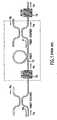
- FIG. 1 illustrates a prior art optical amplifier which utilizes Raman scattering to amplify a signal wavelength.
- a pump wavelength ⁇ p and a signal wavelength ⁇ s are co-injected in opposite directions into a Raman-active transmission medium 10 (e.g., fused silicon).
- Co-propagating pumps may be used, although a counter-propagation pump scheme reduces polarization sensitivity and cross talk between wavelength division multiplexed (WDM) channels.
- WDM wavelength division multiplexed
- the pump wavelength ⁇ p amplifies the signal wavelength ⁇ s and, in so doing, it is diminished in strength.
- This gain process is called stimulated Raman scattering (SRS) and is a well-known technique for amplifying an optical signal.
- SRS stimulated Raman scattering
- the two wavelengths ⁇ p and ⁇ s are referred to as being "SRS coupled" to each other.
- a filter 16 transmits all signals of the signal wavelength ⁇ s and blocks signals of the pump wavelength ⁇ p thereby filtering out the pump wavelength.
- Figure 1A illustrates the gain curve for a signal wavelength ⁇ s amplified using a single pump wavelength ⁇ p.
- a broad bandwidth e.g. 300nm in silica
- a portion of it e.g., about 50 nm
- the effective Raman gain is determinable by one skilled in the art and depends on a number of factors including the desired degree of amplification and the desired flatness across the amplification bandwidth.
- the effective Raman gain having less than 3dB gain variation extends about 25 nm on either side of the peak Raman Stokes shift of about 100 nm. Therefore, the bandwidth of the effective Raman gain occurs from about 75 to about 125 nm from the pump wavelength as shown between points A and B on the Raman gain curve in Figure 1A .
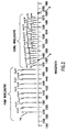
- FIG. 2 is a schematic drawing illustrating the relationship between pump wavelengths and the signal wavelengths of a prior art Raman amplifier.
- the schematic of Figure 2 shows multiple pump wavelengths wp through ⁇ p+n which are used to amplify signal wavelengths ws through ws+m. Because the effective Raman gain occurs about 75 to about 125 nm from the pump signal, signal wavelengths separated from a pump wavelength within this range will be effectively SRS coupled to the pump wavelength.
- pump wavelength ⁇ p (1370 nm) is separated from signal wavelength ws (1470 nm) by approximately 100 nm.
- the transmission medium 10 of Fig. 1 is silica
- pump wavelength wp will be SRS coupled to and amplify signal wavelength ⁇ s.
- BSR backward Rayleigh scattering
- a pump wavelength generated at point A and intended to amplify a signal wavelength at point B would coincide with signal wavelength ⁇ s+2.
- the BSR from the pump wavelength at point A is affected by the Raman gain of the lower pump wavelengths, thus introducing undesired noise into the signal wavelengths near point A ( Fig. 2 ).
- BSR both decreases the Raman amplification of the adjacent signals by depleting the pump wavelengths' power, and diminishes signal quality by introducing noise and cross-talk between the channels.
- BSR also causes a four-wave-mixing effect.
- Four-wave-mixing is defmed by third order susceptibility in the relation between the induced polarization from the electric dipoles and electric field.
- a strong pump wave at a frequency ⁇ 1 creates two side bands located symmetrically at the frequencies ⁇ 2 and ⁇ 3 .
- the two side bands may also introduce undesired noise into the signal wavelengths.
- WO00/49721 discloses a Raman amplification system in which the pump source is configured to provide a plurality of pump wavelengths interleaved with the signal wavelength ranges.
- the amplification bandwidth of a Raman amplifier is expanded by interleaving narrow pump wavelengths between signal wavelengths, thereby avoiding interaction between the signal wavelengths and the backward Rayleigh scattering (BRS) of the interleaved pump wavelengths.
- the line width of the pump signals are narrow enough (e.g. less than 1 GHz) compared to the wavelength spacing of the signal wavelengths (e.g., as low as 25 GHz) so that the BRS of the interleaved pump wavelengths is readily distinguishable from signal wavelengths and can be efficiently filtered out.
- One aspect of the present invention is a method of Raman amplification employing interleaved pump and signal wavelengths.
- the method comprises effecting a plurality of pump wavelengths on a Raman-active transmission medium which is transmitting counter-propagating signal wavelengths, wherein one or more of the pump wavelengths are interleaved between the signal wavelengths.
- the plurality of pump wavelengths spans a bandwidth that exceeds the peak Raman Stokes Shift of the transmission medium.
- the method further comprises the step of reducing backward Rayleigh scattering (BRS) generated from the interleaved pump wavelengths.
- BRS backward Rayleigh scattering
- the system comprises: (a) a pump for generating a plurality of pump wavelengths wherein at least one of the pump wavelengths is between two of the signal wavelengths; and (b) a coupler for coupling the pump wavelengths to the transmission medium such that the pump wavelengths and the signal wavelengths are counter-propagating.
- the pump is adapted to generate pump wavelengths over a bandwidth greater than that of the peak Raman Stokes Shift.
- the cable system comprises: (a) a transmission path; (b) a signal transmitter coupled to the transmission path and adapted for transmitting signal wavelengths; (c) a signal receiver coupled to the transmission path and adapted for receiving the signal wavelengths; and (d) at least one amplifier system as described above disposed along the transmission path between the signal transmitter and the signal receiver.
- FIG 3 is a schematic drawing illustrating the relationship between the pump wavelengths and signal wavelengths of a Raman amplifier using the method and apparatus of the present invention.
- a band of pump wavelengths ⁇ p 1 through ⁇ p 1 +n are shown.
- the bandwidth BWP of the pump wavelengths ⁇ p 1 through ⁇ p 1 +n exceeds one maximum gain Raman shift of the transmission medium.
- the bandwidth of the pump wavelengths exceeds about 10% of the peak Stokes Shift, and more preferable, exceeds about 20% of the peak Stokes Shift.
- the bandwidth BWP of the pump wavelengths ⁇ p 1 through ⁇ p 1 +n is 120 nm which exceeds one Raman maximum gain shift of silica by approximately 20 nm.
- the pump wavelengths ⁇ p 1 +10, ⁇ p 1 +11, ⁇ p 1 +n which overlap the signal wavelengths ⁇ s 1 , ⁇ s 1 +1, ⁇ s 1 +2, ⁇ s 1 +3, ⁇ s 1 +4, and ⁇ s 1 +5 are situated between the signal wavelengths.
- the line width of the pump wavelengths is narrow enough compared to the wavelength spacing of the signal wavelengths that the backward Rayleigh scattering (BRS) generated from the pump wavelengths can be identified as such and efficiently filtered out.
- the minimum wavelength separation between the signal wavelengths referred to herein as the "stop bandwidth" or the "100% rejection band of the filter,” is related to the repetition rate, modulation format, signal strength, and transmission distance of the signal wavelength.
- the separation between signal wavelengths may be no less than 0.2 nm (25 GHz at 1550 nm).
- a wider channel spacing is typically used in conventional transmission systems.
- a pump signal is preferably no wider than about 1/50 of the channel separation, and, more preferably, no wider than about 1/100 of the channel separation.
- the pump wavelength is positioned between signal wavelengths such that it appears in the middle between the adjacent signals.
- the accuracy to which a DFB laser can be tuned to a particular wavelength can be better than 0.01 nm (approximately 1.3 GHz).
- Figure 3A illustrates, in a simplified manner, the relationship between the pump wavelengths and signal wavelengths of a Raman amplifier using the method and apparatus of the present invention.
- the stop bandwidth is the area between the effective transmission bandwidth of the signal bandwidth, and within the stop bandwidth, a significantly narrower pump linewidth is effected. As described herein, this allows effective filtering of any BRS generated from the pump wavelengths.
- FIG. 4 illustrates an exemplary embodiment of a Raman amplifier system in accordance with the present invention.
- pump source 44 injects pump wavelengths onto a fiber span 40.
- pump source 44 comprises a distributed feedback (DFB) laser, which can provide wavelength stability of better than 0.1 nm. Wavelength stability depends partially on the filter characteristic, that is, the breadth of the 100% rejection band. It is in this area that, in accordance with the present invention, the narrow pump wavelengths are effected. In an ideal step-like (i.e., rectangular shape) filter, this will require a stability of better than 1/4 of the filter stop bandwidth with the line width of the pump being less than 1/10 of the filter stop bandwidth.
- DFB distributed feedback
- This bandwidth should be as narrow as possible so as not to decrease the effective channel transmission bandwidth. At the same time, it should be broad enough to allow for a given pump wavelength to be filtered out with maximum efficiency. Assuming the bandwidth and the wavelength stability of a pump equal to 1 GHz, the estimate for the filter stop bandwidth will be 4 GHz. It is desirable in practice to utilize an even smaller bandwidth, especially for a channel separation of less than 0.5 nm.
- the requirements when amplifying non-modulated signals are broader because the line width of a CW signal is more than three orders of magnitude narrower than the bandwidth of a modulated RZ format signal at 10 Ghz.
- DFB lasers emit wavelengths having line widths of less than 100 MHz and can deliver up to 20-30 mW of average power at the wavelength region of 1550 nm. These power levels are sufficient for amplification of the signal wavelengths when a pump scheme is used employing numerous, closely-packed pump wavelengths (e.g., when pump wavelength separation is less than 4 nm). As the wavelength separation between pumps increases, so must the power per pump wavelength. Pump power will also depend on signal power and the separation of the signals. The higher the required signal power and the smaller the separation between signal channels, the more pump power will be needed.
- Filter 45 is tuned to transmit only signal wavelengths and not pump wavelengths. Suitable filters include, for example, Fabry-Perot filters and Mach-Zehnder wavelength multiplexers. Ideally, the transmission characteristics of the filter 45 are such that it permits maximum transmittance at the signal wavelengths and minimum transmittance at the pump wavelengths. Thus, the filter will pass the signal wavelengths and filter any signals occurring between the signal wavelengths, including BRS of the pump signals preferably in the 20nm or more overlap area.
- Isolator 46 provides unidirectional propagation and eliminates any multipath Rayleigh scattering effect and any reflection of the counter-proprogating radiation from the filter.
- Figure 5 illustrates the results of a numerical simulation of a Raman amplifier having 120 nm bandwidths. As shown, a gain ripple of less than 0.3 dB is achieved with 38 pump wavelengths (only 10 pump wavelengths are interleaved with signal wavelengths) situated at 4 nm spacing, illustrated by the relatively stable amplitude of the amplified signals at approximately - 7 dBm. This numerical simulation is performed for 61 channel signals separated by 2nm widths, thereby providing -7dBm (0.2 mW) power per channel.
- the fiber span is represented as being 50 km long and consisting of standard telecommunication fiber with losses of 0.2 dB/km at 1550 nm. The total span loss at 1550 nm is 10 dB.
- Pump wavelengths start from 1360nm (not shown) and end at 1512 nm. Signals start from 1475 nm and end at 1595 nm, covering three telecommunication bands (S, C, and L).
- the pump power starts at approximately 130 mW per pump and drops to below 10 mW above 1430 nm. Total pump power in the simulation is 1185 mW. This means that for the majority of pump wavelengths there will be no limitation on line width and precise positioning. These limitations will only apply for the wavelength region where the pump and signal bandwidths intersect (10 pumps for the simulation under discussion). In practice the number of pump wavelengths which coincide with signal bandwidths can be reduced. Utilization of fibers with smaller cross sections will reduce the required pump power.
Landscapes
- Physics & Mathematics (AREA)
- Electromagnetism (AREA)
- Engineering & Computer Science (AREA)
- Plasma & Fusion (AREA)
- Optics & Photonics (AREA)
- Computer Networks & Wireless Communication (AREA)
- Signal Processing (AREA)
- Optical Modulation, Optical Deflection, Nonlinear Optics, Optical Demodulation, Optical Logic Elements (AREA)
- Lasers (AREA)
Abstract
Description
- This invention pertains to Raman amplifiers and, more particularly, to Raman amplifiers having a bandwidth which exceeds the peak Raman Stokes gain shift of the transmission medium with which the Raman amplifier is utilized.
- Optical fiber technology is currently utilized in communications systems to transfer information, e.g., voice signals and data signals, over long distances as optical signals. Over such long distances, however, the strength and quality of a transmitted optical signal diminishes. Accordingly, techniques have been developed to regenerate or amplify optical signals as they propagate along an optical fiber.
- One well-known amplifying technique exploits an effect called Raman scattering to amplify an incoming information-bearing optical signal (referred to herein as a "signal wavelength"). Raman scattering describes the interaction of light with molecular vibrations of the material through which the light propagates (referred to herein as the "transmission medium"). Incident light scattered by molecules experiences a downshift in frequency from the power-bearing optical signal (referred to herein as the "pump wavelength"). This downshift in frequency (or increase in wavelength) from the pump wavelength is referred to as the "Stokes Shift." The downshift of the peak gain from the pump wavelength is referred to herein as the "peak Stokes shift." The extent of the downshift and the shape of the Raman gain curve is determined by the molecular-vibrational frequency modes of the transmission medium. In amorphous materials, such as silica, molecular-vibrational frequencies spread into bands which overlap and provide a broad bandwidth gain curve. For example, in silica fibers, the gain curve extends over a bandwidth of about 300nm from the pump wavelength and has a peak Stokes shift of about 100 nm.
- The overall concept of Raman scattering is well known and is described in numerous patents and publications, for example, R.M. Stolen, E.P. Ippen, and A.R. Tynes, "Raman Oscillation in Glass Optical Waveguides," Appl. Phys. Lett, 1972 v. 20, 2 PP62-64 ; and R.M. Stolen, E.P. Ippen, Raman Gain in Glass Optical Waveguides," Appl. Phys. Lett, 1973 v. 23, 6 pp. 276-278). With respect to the present invention, the most relevant aspect of Raman scattering is its effect on signal wavelengths traveling along the transmission medium.
-
Figure 1 illustrates a prior art optical amplifier which utilizes Raman scattering to amplify a signal wavelength. Referring toFigure 1 , a pump wavelength ωp and a signal wavelength ωs are co-injected in opposite directions into a Raman-active transmission medium 10 (e.g., fused silicon). Co-propagating pumps may be used, although a counter-propagation pump scheme reduces polarization sensitivity and cross talk between wavelength division multiplexed (WDM) channels. Providing the wavelength of the signal wavelength ωs is within the Raman gain of power wavelength ωp (e.g., about 300 nm in silica), the signal wavelength ωs will experience optical gain generated by, and at the expense of, the pump wavelength ωp. In other words, the pump wavelength ωp amplifies the signal wavelength ωs and, in so doing, it is diminished in strength. This gain process is called stimulated Raman scattering (SRS) and is a well-known technique for amplifying an optical signal. The two wavelengths ωp and ωs are referred to as being "SRS coupled" to each other. Afilter 16 transmits all signals of the signal wavelength ωs and blocks signals of the pump wavelength ωp thereby filtering out the pump wavelength. -
Figure 1A illustrates the gain curve for a signal wavelength ωs amplified using a single pump wavelength ωp. As shown inFig. 1A , while gain occurs over a broad bandwidth (e.g. 300nm in silica), only a portion of it (e.g., about 50 nm) is, from a practical standpoint, useable to effectively amplify the signal wavelength ωs. This useable bandwidth is referred to herein as the "effective Raman gain." The effective Raman gain is determinable by one skilled in the art and depends on a number of factors including the desired degree of amplification and the desired flatness across the amplification bandwidth. In silica, the effective Raman gain having less than 3dB gain variation extends about 25 nm on either side of the peak Raman Stokes shift of about 100 nm. Therefore, the bandwidth of the effective Raman gain occurs from about 75 to about 125 nm from the pump wavelength as shown between points A and B on the Raman gain curve inFigure 1A . -
Figure 2 is a schematic drawing illustrating the relationship between pump wavelengths and the signal wavelengths of a prior art Raman amplifier. The schematic ofFigure 2 shows multiple pump wavelengths wp through ωp+n which are used to amplify signal wavelengths ws through ws+m. Because the effective Raman gain occurs about 75 to about 125 nm from the pump signal, signal wavelengths separated from a pump wavelength within this range will be effectively SRS coupled to the pump wavelength. InFigure 2 , pump wavelength ωp (1370 nm) is separated from signal wavelength ws (1470 nm) by approximately 100 nm. Thus, assuming that thetransmission medium 10 ofFig. 1 is silica, pump wavelength wp will be SRS coupled to and amplify signal wavelength ωs. - If only a single pump wavelength wp is used, only signals in the bandwidth from ωs - 25 nm to ws + 25 nm would be within the effective Raman gain. However, the use of multiple pump wavelengths ωp through ωp+n as shown in
Fig. 2 allows the gain bandwidth to be expanded to amplify signal wavelengths ωs through ws+m. Furthermore, the use of multiple pump wavelengths serves to reduce gain variation (improve flatness) within this bandwidth due to the cumulative effect of multiple gain curves. - Despite multiple pump configurations, prior art Raman amplifiers are nevertheless limited in bandwidth, which in turn limits the capacity of WDM systems. More specifically, because the effective Raman gain tails off at about 125 nm from the pump wavelength, signal wavelengths beyond this point are not effectively amplified. Furthermore, the applicants have found that in multi-pump systems, where excellent flatness in amplification is achievable through the cumulative effect of multiple gain curves, signal wavelengths preferably should be within the peak Stokes shift of a pump wavelength, e.g., about 100nm, for optimum flatness. This limitation in SRS coupling limits the bandwidth of signals, e.g. ωs from ωs+m as shown in
Fig. 2 , to the peak Stokes shift of a pump wavelength since extending the signal bandwidth beyond ωs+m would require introducing pump wavelengths into the signal bandwidth, beyond ωs. - Injecting pump wavelengths into the signal bandwidth, however, has traditionally been avoided due to backward Rayleigh scattering (BSR) resulting from the pump signals. BRS results from random localized variations of the molecular positions in glass that create random inhomogeneities of the reflective index that act as tiny scatter centers. Although the pump and signal wavelengths can be easily separated by filtering in a counter-proprogating scheme, the BSR from the pump wavelengths, which propagates in the direction of the signals, is not easily filtered. Furthermore, BSR from longer pump wavelengths falls into the Raman gain generated by shorter pump wavelengths, thereby causing this BRS to be amplified such that it equals or exceeds the intensity of the signal wavelengths. For example, a pump wavelength generated at point A and intended to amplify a signal wavelength at point B would coincide with signal wavelength ωs+2. The BSR from the pump wavelength at point A is affected by the Raman gain of the lower pump wavelengths, thus introducing undesired noise into the signal wavelengths near point A (
Fig. 2 ). Thus, BSR both decreases the Raman amplification of the adjacent signals by depleting the pump wavelengths' power, and diminishes signal quality by introducing noise and cross-talk between the channels. - BSR also causes a four-wave-mixing effect. Four-wave-mixing is defmed by third order susceptibility in the relation between the induced polarization from the electric dipoles and electric field. In a particular case of four-wave-mixing in optical fibers, a strong pump wave at a frequency ω1 creates two side bands located symmetrically at the frequencies ω2 and ω3. The frequency shift of the side bands is given by Ωs= ω1- ω2= ω3- ω1, where ω2< ω3. The phase matching requirement for this process is k2-k3-2k1=0, where k is the wave number. The two side bands may also introduce undesired noise into the signal wavelengths.
-
WO00/49721 - Accordingly, it would be desirable to have a method and apparatus for expanding the gain bandwidth of a Raman amplifier beyond the maximum gain Raman Stokes Shift of the transmission medium without the attendant problems of BSR.
- The invention is defined in
claims - In accordance with the present invention, the amplification bandwidth of a Raman amplifier is expanded by interleaving narrow pump wavelengths between signal wavelengths, thereby avoiding interaction between the signal wavelengths and the backward Rayleigh scattering (BRS) of the interleaved pump wavelengths. The line width of the pump signals are narrow enough (e.g. less than 1 GHz) compared to the wavelength spacing of the signal wavelengths (e.g., as low as 25 GHz) so that the BRS of the interleaved pump wavelengths is readily distinguishable from signal wavelengths and can be efficiently filtered out.
- One aspect of the present invention is a method of Raman amplification employing interleaved pump and signal wavelengths. In a preferred embodiment, the method comprises effecting a plurality of pump wavelengths on a Raman-active transmission medium which is transmitting counter-propagating signal wavelengths, wherein one or more of the pump wavelengths are interleaved between the signal wavelengths. Preferably, the plurality of pump wavelengths spans a bandwidth that exceeds the peak Raman Stokes Shift of the transmission medium. In a preferred embodiment, the method further comprises the step of reducing backward Rayleigh scattering (BRS) generated from the interleaved pump wavelengths.
- Another aspect of the present invention is a Raman amplification system for amplifying signal wavelengths propagating on a transmission medium by interleaving signal and pump wavelengths. In a preferred embodiment, the system comprises: (a) a pump for generating a plurality of pump wavelengths wherein at least one of the pump wavelengths is between two of the signal wavelengths; and (b) a coupler for coupling the pump wavelengths to the transmission medium such that the pump wavelengths and the signal wavelengths are counter-propagating. Preferably, the pump is adapted to generate pump wavelengths over a bandwidth greater than that of the peak Raman Stokes Shift.
- Yet another aspect of the present invention is a long-haul cable system employing the amplification system as described above. In a preferred embodiment, the cable system comprises: (a) a transmission path; (b) a signal transmitter coupled to the transmission path and adapted for transmitting signal wavelengths; (c) a signal receiver coupled to the transmission path and adapted for receiving the signal wavelengths; and (d) at least one amplifier system as described above disposed along the transmission path between the signal transmitter and the signal receiver.
-
-
Figure 1 is a block diagram of a prior art Raman amplifier; -
Figure 1A illustrates the gain curve for a signal wavelength, amplified using a single pump wavelength in accordance with the prior art; -
Figure 2 is a schematic drawing illustrating the relationship between the pump wavelengths and the signal wavelengths of a prior art multiple-pump Raman amplifier; -
Figure 3 is a schematic drawing illustrating the relationship between the pump wavelengths and the signal wavelengths of a Raman amplifier using the method and apparatus of the present invention; -
Figure 3A is a simplified schematic drawing illustrating the relationship between the pump wavelengths and the signal wavelengths of a Raman amplifier using the method and apparatus of the present invention; -
Figure 4 is a block diagram of a Raman amplifier in accordance with the present invention; and -
Figure 5 is a graph showing the gain ripple of the output of a Raman amplifier in accordance with the present invention. -
Figure 3 is a schematic drawing illustrating the relationship between the pump wavelengths and signal wavelengths of a Raman amplifier using the method and apparatus of the present invention. Referring toFigure 3 , a band of pump wavelengths ωp1 through ωp1+n are shown. The bandwidth BWP of the pump wavelengths ωp1 through ωp1+n exceeds one maximum gain Raman shift of the transmission medium. Preferably, the bandwidth of the pump wavelengths exceeds about 10% of the peak Stokes Shift, and more preferable, exceeds about 20% of the peak Stokes Shift. In the example ofFigure 3 , the bandwidth BWP of the pump wavelengths ωp1 through ωp1 +n is 120 nm which exceeds one Raman maximum gain shift of silica by approximately 20 nm. - As can be seen in
Fig. 3 , the pump wavelengths ωp1+10, ωp1+11, ωp1+n which overlap the signal wavelengths ωs1, ωs1+1, ωs1+2, ωs1+3, ωs1+4, and ωs1+5 are situated between the signal wavelengths. The line width of the pump wavelengths is narrow enough compared to the wavelength spacing of the signal wavelengths that the backward Rayleigh scattering (BRS) generated from the pump wavelengths can be identified as such and efficiently filtered out. The minimum wavelength separation between the signal wavelengths, referred to herein as the "stop bandwidth" or the "100% rejection band of the filter," is related to the repetition rate, modulation format, signal strength, and transmission distance of the signal wavelength. For example, for a 10 Gb/s repetition rate, the separation between signal wavelengths may be no less than 0.2 nm (25 GHz at 1550 nm). A wider channel spacing is typically used in conventional transmission systems. A pump signal is preferably no wider than about 1/50 of the channel separation, and, more preferably, no wider than about 1/100 of the channel separation. Furthermore, the pump wavelength is positioned between signal wavelengths such that it appears in the middle between the adjacent signals. The accuracy to which a DFB laser can be tuned to a particular wavelength can be better than 0.01 nm (approximately 1.3 GHz). -
Figure 3A illustrates, in a simplified manner, the relationship between the pump wavelengths and signal wavelengths of a Raman amplifier using the method and apparatus of the present invention. As can be seen inFigure 3A , the stop bandwidth is the area between the effective transmission bandwidth of the signal bandwidth, and within the stop bandwidth, a significantly narrower pump linewidth is effected. As described herein, this allows effective filtering of any BRS generated from the pump wavelengths. -
Figure 4 illustrates an exemplary embodiment of a Raman amplifier system in accordance with the present invention. As shown inFig. 4 , pumpsource 44 injects pump wavelengths onto afiber span 40. In a preferred embodiment, pumpsource 44 comprises a distributed feedback (DFB) laser, which can provide wavelength stability of better than 0.1 nm. Wavelength stability depends partially on the filter characteristic, that is, the breadth of the 100% rejection band. It is in this area that, in accordance with the present invention, the narrow pump wavelengths are effected. In an ideal step-like (i.e., rectangular shape) filter, this will require a stability of better than 1/4 of the filter stop bandwidth with the line width of the pump being less than 1/10 of the filter stop bandwidth. This bandwidth should be as narrow as possible so as not to decrease the effective channel transmission bandwidth. At the same time, it should be broad enough to allow for a given pump wavelength to be filtered out with maximum efficiency. Assuming the bandwidth and the wavelength stability of a pump equal to 1 GHz, the estimate for the filter stop bandwidth will be 4 GHz. It is desirable in practice to utilize an even smaller bandwidth, especially for a channel separation of less than 0.5 nm. The requirements when amplifying non-modulated signals are broader because the line width of a CW signal is more than three orders of magnitude narrower than the bandwidth of a modulated RZ format signal at 10 Ghz. - DFB lasers emit wavelengths having line widths of less than 100 MHz and can deliver up to 20-30 mW of average power at the wavelength region of 1550 nm. These power levels are sufficient for amplification of the signal wavelengths when a pump scheme is used employing numerous, closely-packed pump wavelengths (e.g., when pump wavelength separation is less than 4 nm). As the wavelength separation between pumps increases, so must the power per pump wavelength. Pump power will also depend on signal power and the separation of the signals. The higher the required signal power and the smaller the separation between signal channels, the more pump power will be needed.
-
Filter 45 is tuned to transmit only signal wavelengths and not pump wavelengths. Suitable filters include, for example, Fabry-Perot filters and Mach-Zehnder wavelength multiplexers. Ideally, the transmission characteristics of thefilter 45 are such that it permits maximum transmittance at the signal wavelengths and minimum transmittance at the pump wavelengths. Thus, the filter will pass the signal wavelengths and filter any signals occurring between the signal wavelengths, including BRS of the pump signals preferably in the 20nm or more overlap area. -
Isolator 46 provides unidirectional propagation and eliminates any multipath Rayleigh scattering effect and any reflection of the counter-proprogating radiation from the filter. -
Figure 5 illustrates the results of a numerical simulation of a Raman amplifier having 120 nm bandwidths. As shown, a gain ripple of less than 0.3 dB is achieved with 38 pump wavelengths (only 10 pump wavelengths are interleaved with signal wavelengths) situated at 4 nm spacing, illustrated by the relatively stable amplitude of the amplified signals at approximately - 7 dBm. This numerical simulation is performed for 61 channel signals separated by 2nm widths, thereby providing -7dBm (0.2 mW) power per channel. The fiber span is represented as being 50 km long and consisting of standard telecommunication fiber with losses of 0.2 dB/km at 1550 nm. The total span loss at 1550 nm is 10 dB. Pump wavelengths start from 1360nm (not shown) and end at 1512 nm. Signals start from 1475 nm and end at 1595 nm, covering three telecommunication bands (S, C, and L). The pump power starts at approximately 130 mW per pump and drops to below 10 mW above 1430 nm. Total pump power in the simulation is 1185 mW. This means that for the majority of pump wavelengths there will be no limitation on line width and precise positioning. These limitations will only apply for the wavelength region where the pump and signal bandwidths intersect (10 pumps for the simulation under discussion). In practice the number of pump wavelengths which coincide with signal bandwidths can be reduced. Utilization of fibers with smaller cross sections will reduce the required pump power. - While there has been described herein the principles of the invention, it is to be understood by those skilled in the art that this description is made only by way of example and not as a limitation to the scope of the invention. Accordingly, it is intended by the appended claims, to cover all modifications of the invention which fall within the scope of the invention.
Claims (19)
- A method of Raman amplification comprising:effecting a plurality of pump wavelengths on a Raman-active transmission medium (10, 40) transmitting counter-propagating signal wavelengths with respect to the pump wavelengths wherein one or more of said pump wavelengths are interleaved between said signal wavelengths;characterised in that line width of each of said pump wavelengths is narrower than the wavelength spacing of said signal wavelengths so that backward Rayleigh scattered light BRS of said interleaved pump wavelengths is distinguishable from said signal wavelengths.
- The method of claim 1, wherein the plurality of pump wavelengths span a bandwidth that exceeds the peak Raman Stokes Shift of said transmission medium (10, 40).
- The method of claim 2, wherein said transmission medium (10, 40) comprises silica and wherein said peak Raman Stokes shift is about 100 nm.
- The method of claim 1, further comprising:reducing BRS generated from the interleaved pump wavelengths; andfiltering out said BRS from between said signal wavelengths.
- The method of claim 1, wherein said signal wavelengths are separated by a bandgap and each of the interleaved pump wavelengths is no wider than about 1/10 of said bandgap.
- The method of claim 5, wherein each of the interleaved pump wavelengths is no wider than about 1/20 of said bandgap.
- The method of claim 6, wherein each of the interleaved pump wavelengths is no closer than about 1/2 of the channel wavelength separation minus the sum of the pump source wavelength and the pump line width.
- The method of claim 7, further comprising:reducing BRS generated from the interleaved pump wavelengths; andfiltering out said BRS from between said signal wavelengths.
- The method of Raman amplification of claim 1 in which the gain bandwidth of an amplifier performing the amplification exceeds the Raman Stokes Shift of the transmission medium in which the amplifier is situated, comprising:effecting an information-bearing signal comprising a plurality of wavelengths on said transmission medium (10, 40); andeffecting a pump signal comprising the plurality of pump wavelengths onto said transmission medium, wherein the difference in wavelength between at least two of said pump wavelengths exceeds the peak Raman gain of said transmission medium (10, 40) and wherein any of the pump wavelengths that overlap said information-bearing signal are interleaved with said signal wavelengths.
- A method of Raman amplification as set forth in claim 4, wherein said transmission medium comprises silica and wherein the spectral shape of said pump wavelengths and said signal wavelengths are Gaussian and have line widths no greater than about 1/50th of the signal separation between adjacent signal wavelengths.
- A Raman amplification system for amplifying signal wavelengths propagating on a transmission medium (10, 40), said system comprising:a pump (42, 44) for generating a plurality of pump wavelengths wherein at least one of said pump wavelengths is between two adjacent signal wavelengths;a coupler for coupling said pump wavelengths to said transmission medium such that said pump wavelengths and said signal wavelengths are counter-propagating;characterised in that the line width of each of said pump wavelengths is narrower than the wavelength spacing of said signal wavelengths so that the backward Rayleigh scattered light BRS of said interleaved pump wavelengths is distinguishable from said signal wavelengths.
- The Raman amplification system of claim 11, wherein said pump (42, 44) is adapted to generate pump wavelengths covering a bandwidth greater than that of the peak Raman Stokes shift.
- The Raman amplification system of claim 11, wherein said pump (42, 44) is adapted to generate wavelengths that are no wider than about 1/10 of the bandgap between adjacent signal wavelengths.
- The Raman amplification system of claim 13, wherein said pump (42, 44) is adapted to generate wavelengths that are no wider than about 1/20 of said bandgap.
- The Raman amplification system of claim 14, wherein said pump (42, 44) is a distributed feedback laser.
- The Raman amplification system of claim 11, further comprising:a filter (43, 45) optically coupled to said transmission medium (10, 40) and tuned to block transmission of said pump wavelengths while transmitting said signal wavelengths.
- The Raman amplification system of claim 11, further comprising:a filter (43, 45) optically connected to said transmission medium for reducing the BRS of pump wavelengths interleaved with said signal wavelengths.
- The Raman amplification system of claim 16, wherein said filter (43, 45) comprises a Fabry-Perot filter.
- The Raman amplification system of claim 16, wherein said filter comprises a Mach-Zehnder wavelength multiplexer.
Applications Claiming Priority (3)
| Application Number | Priority Date | Filing Date | Title |
|---|---|---|---|
| US678081 | 2000-10-03 | ||
| US09/678,081 US6424455B1 (en) | 2000-10-03 | 2000-10-03 | Wide bandwidth fiber raman amplifier |
| PCT/US2001/030542 WO2002029943A2 (en) | 2000-10-03 | 2001-09-28 | Wide bandwidth fiber raman amplifier |
Publications (2)
| Publication Number | Publication Date |
|---|---|
| EP1323217A2 EP1323217A2 (en) | 2003-07-02 |
| EP1323217B1 true EP1323217B1 (en) | 2012-06-27 |
Family
ID=24721299
Family Applications (1)
| Application Number | Title | Priority Date | Filing Date |
|---|---|---|---|
| EP01977276A Expired - Lifetime EP1323217B1 (en) | 2000-10-03 | 2001-09-28 | Wide bandwidth fiber raman amplifier |
Country Status (5)
| Country | Link |
|---|---|
| US (1) | US6424455B1 (en) |
| EP (1) | EP1323217B1 (en) |
| JP (1) | JP2004519091A (en) |
| AU (1) | AU2001296409A1 (en) |
| WO (1) | WO2002029943A2 (en) |
Families Citing this family (27)
| Publication number | Priority date | Publication date | Assignee | Title |
|---|---|---|---|---|
| US6008373A (en) | 1995-06-07 | 1999-12-28 | Carnegie Mellon University | Fluorescent labeling complexes with large stokes shift formed by coupling together cyanine and other fluorochromes capable of resonance energy transfer |
| AU2001253090A1 (en) * | 2000-04-03 | 2001-10-15 | Bristol-Myers Squibb Pharma Company | Cyclic lactams as inhibitors of abeta protein production |
| JP4551007B2 (en) * | 2001-02-06 | 2010-09-22 | 富士通株式会社 | Raman amplifier and optical transmission system using the same |
| DE10111491A1 (en) * | 2001-03-09 | 2002-09-19 | Siemens Ag | Pump source with several pump lasers each for Raman amplification of a WDM signal with minimized four-wave mixing |
| DE10111969B4 (en) * | 2001-03-13 | 2004-04-15 | Siemens Ag | Multiplexer for realizing non-equidistant distances between the pump wavelengths in broadband Raman amplifiers |
| US6867905B1 (en) * | 2001-03-28 | 2005-03-15 | Cisco Technolog, Inc. | Reduced four-wave mixing and raman amplification architecture |
| US6624928B1 (en) * | 2001-05-24 | 2003-09-23 | Nortel Networks Limited | Raman amplification |
| JP3824974B2 (en) * | 2001-07-13 | 2006-09-20 | 古河電気工業株式会社 | Raman light amplification system |
| US6614586B2 (en) * | 2001-07-30 | 2003-09-02 | Dorsal Networks, Inc. | Methods and systems for high performance, wide bandwidth optical communication systems using Raman amplification |
| JP3808734B2 (en) * | 2001-08-10 | 2006-08-16 | 富士通株式会社 | Raman amplifier |
| JP3808766B2 (en) * | 2001-12-21 | 2006-08-16 | 富士通株式会社 | Raman amplifier and optical transmission system |
| EP1330056A1 (en) * | 2002-01-16 | 2003-07-23 | Lucent Technologies Inc. | Method and contrivance for applying Raman amplification in an optical device |
| CA2422206C (en) * | 2002-03-15 | 2011-06-14 | Tyco Telecommunications (Us) Inc. | Hybrid raman/erbium-doped fiber amplifier and transmission system with dispersion map |
| US6646786B1 (en) | 2002-05-06 | 2003-11-11 | Cisco Technology, Inc. | Copropagating Raman pump unit to suppress four-wave mixing crosstalk between pump modes and WDM signals |
| WO2003107497A1 (en) | 2002-06-14 | 2003-12-24 | Fujitsu Limited | Raman amplification system utilizing bi-directional pumping |
| US6992814B2 (en) * | 2002-06-17 | 2006-01-31 | Avanex Corporation | Wide-band raman amplifiers |
| EP1376905B1 (en) * | 2002-06-28 | 2013-06-05 | Sumitomo Electric Industries, Ltd. | Optical transmission system with Raman amplification |
| JP2004086143A (en) | 2002-06-28 | 2004-03-18 | Sumitomo Electric Ind Ltd | Optical transmission system |
| US20040036959A1 (en) * | 2002-08-20 | 2004-02-26 | Evangelides Stephen G. | Optical transmission system employing erbium-doped optical amplifiers and Raman amplifiers |
| US6782174B1 (en) * | 2003-02-11 | 2004-08-24 | Tyco Telecommunications (Us) Inc. | Method of repairing a slope-matched cable system and replacement cable portion for use therein |
| JP2004301991A (en) * | 2003-03-31 | 2004-10-28 | Fujitsu Ltd | Optical amplification control unit and optical amplification control method |
| US7054059B1 (en) | 2003-05-14 | 2006-05-30 | Cisco Technoloy, Inc. | Lumped Raman amplification structure for very wideband applications |
| US7058268B2 (en) * | 2003-08-07 | 2006-06-06 | Tyco Telecommunications (Us) Inc. | Deployable optical fiber transmission lines, optical transmission cable, and method of making same |
| DE10336240B4 (en) * | 2003-08-07 | 2016-06-30 | Xieon Networks S.À.R.L. | Arrangement for reducing reflection interference in a transmission system with at least one connected Raman pump source |
| DE602004006007T2 (en) * | 2004-12-23 | 2007-12-20 | Alcatel Lucent | Method for controlling the gain of a Raman amplifier |
| US7167299B1 (en) * | 2006-01-31 | 2007-01-23 | Lucent Technologies Inc. | Method and apparatus for controlling pump powers of broadband Raman amplifiers in optical transmission systems incorporating virtual channels to reduce noise |
| DE102008017740A1 (en) * | 2008-04-07 | 2009-10-15 | Lios Technology Gmbh | Apparatus and method for calibrating a fiber optic temperature measuring system |
Family Cites Families (6)
| Publication number | Priority date | Publication date | Assignee | Title |
|---|---|---|---|---|
| US5321707A (en) * | 1992-07-27 | 1994-06-14 | General Instrument Corporation | Remote pumping for active optical devices |
| GB9510742D0 (en) * | 1995-05-26 | 1995-07-19 | Imperial College | A resonant cascade-raman radiation source |
| US6320884B1 (en) * | 1998-02-26 | 2001-11-20 | Tycom (Us) Inc., | Wide bandwidth Raman amplifier employing a pump unit generating a plurality of wavelengths |
| US6344922B1 (en) * | 1998-07-21 | 2002-02-05 | Corvis Corporation | Optical signal varying devices |
| EP2315073B1 (en) * | 1998-07-23 | 2014-12-31 | The Furukawa Electric Co., Ltd. | Raman amplifier and Raman amplification method |
| US6052219A (en) * | 1999-02-16 | 2000-04-18 | Tyco Submarine Systems Ltd. | Wide bandwidth Raman amplifier capable of employing pump energy spectrally overlapping the signal |
-
2000
- 2000-10-03 US US09/678,081 patent/US6424455B1/en not_active Expired - Lifetime
-
2001
- 2001-09-28 AU AU2001296409A patent/AU2001296409A1/en not_active Abandoned
- 2001-09-28 WO PCT/US2001/030542 patent/WO2002029943A2/en not_active Ceased
- 2001-09-28 JP JP2002533446A patent/JP2004519091A/en not_active Withdrawn
- 2001-09-28 EP EP01977276A patent/EP1323217B1/en not_active Expired - Lifetime
Also Published As
| Publication number | Publication date |
|---|---|
| WO2002029943A3 (en) | 2002-10-03 |
| JP2004519091A (en) | 2004-06-24 |
| WO2002029943A2 (en) | 2002-04-11 |
| EP1323217A2 (en) | 2003-07-02 |
| AU2001296409A1 (en) | 2002-04-15 |
| US6424455B1 (en) | 2002-07-23 |
Similar Documents
| Publication | Publication Date | Title |
|---|---|---|
| EP1323217B1 (en) | Wide bandwidth fiber raman amplifier | |
| EP1022870B1 (en) | Optical communication system using multiple-order Raman amplifiers | |
| US6191877B1 (en) | WDM optical fiber system using Raman amplification | |
| US4699452A (en) | Optical communications system comprising Raman amplification means | |
| JP2001069080A (en) | Method, optical device and system for optical fiber transmission | |
| US6671083B2 (en) | Raman amplifier and optical transmission system | |
| US6529315B2 (en) | Optical amplifier providing dispersion compensation | |
| US6181467B1 (en) | Optical fiber amplifier using synchronized etalon filter | |
| US6717963B1 (en) | Raman fiber amplifier using a wide bandwidth continuous wave pump | |
| US6587606B1 (en) | Waveguide fiber dispersion compensating regenerator | |
| JP2001024594A (en) | Optical amplifier and system having the optical amplifier | |
| Hui et al. | Frequency response of cross-phase modulation in multispan WDM optical fiber systems | |
| US20050207703A1 (en) | Method of suppressing non-linearities in an optical communication system | |
| CA2351268C (en) | Raman amplifier with gain enhancement from optical filtering | |
| EP1469621B1 (en) | Raman amplifying device and method for pump modulation | |
| US7440164B2 (en) | Apparatus and method for Raman gain spectral control | |
| US6862132B1 (en) | Suppression of double rayleigh backscattering and pump reuse in a raman amplifier | |
| WO2002035741A2 (en) | System and method for optical fiber telecommunication by simultaneous transmission in two optical windows | |
| KR20090007356A (en) | System and method for implementing a no-booster optical communication system | |
| JP2003050410A (en) | Method of amplifying wavelength division multiplexing (WDM) signal in WDM transmission system, and optical amplifier, optical amplification system, and WDM transmission system therefor | |
| US7924496B2 (en) | Apparatus and method for Raman gain control | |
| Sugie | Maximum repeaterless transmission of lightwave systems imposed by stimulated Brillouin scattering in fibres | |
| US20030077032A1 (en) | Long distance optical transmission system for high dynamic range signals | |
| KR0183909B1 (en) | Erbium-doped Fiber Amplifier with Flat Gain | |
| KR100326151B1 (en) | Raman fiber amplifier with enhanced signal-to-noise ratio and method for the use thereof |
Legal Events
| Date | Code | Title | Description |
|---|---|---|---|
| PUAI | Public reference made under article 153(3) epc to a published international application that has entered the european phase |
Free format text: ORIGINAL CODE: 0009012 |
|
| 17P | Request for examination filed |
Effective date: 20020531 |
|
| AK | Designated contracting states |
Designated state(s): AT BE CH CY DE DK ES FI FR GB GR IE IT LI LU MC NL PT SE TR |
|
| AX | Request for extension of the european patent |
Extension state: AL LT LV MK RO SI |
|
| RBV | Designated contracting states (corrected) |
Designated state(s): AT BE FR GB |
|
| REG | Reference to a national code |
Ref country code: DE Ref legal event code: 8566 |
|
| 17Q | First examination report despatched |
Effective date: 20090831 |
|
| RAP1 | Party data changed (applicant data changed or rights of an application transferred) |
Owner name: TYCO ELECTRONICS SUBSEA COMMUNICATIONS LLC |
|
| GRAP | Despatch of communication of intention to grant a patent |
Free format text: ORIGINAL CODE: EPIDOSNIGR1 |
|
| RBV | Designated contracting states (corrected) |
Designated state(s): FR GB |
|
| GRAS | Grant fee paid |
Free format text: ORIGINAL CODE: EPIDOSNIGR3 |
|
| GRAA | (expected) grant |
Free format text: ORIGINAL CODE: 0009210 |
|
| AK | Designated contracting states |
Kind code of ref document: B1 Designated state(s): FR GB |
|
| REG | Reference to a national code |
Ref country code: GB Ref legal event code: FG4D |
|
| PGFP | Annual fee paid to national office [announced via postgrant information from national office to epo] |
Ref country code: GB Payment date: 20120925 Year of fee payment: 12 |
|
| PGFP | Annual fee paid to national office [announced via postgrant information from national office to epo] |
Ref country code: FR Payment date: 20121001 Year of fee payment: 12 |
|
| PLBE | No opposition filed within time limit |
Free format text: ORIGINAL CODE: 0009261 |
|
| STAA | Information on the status of an ep patent application or granted ep patent |
Free format text: STATUS: NO OPPOSITION FILED WITHIN TIME LIMIT |
|
| 26N | No opposition filed |
Effective date: 20130328 |
|
| GBPC | Gb: european patent ceased through non-payment of renewal fee |
Effective date: 20130928 |
|
| REG | Reference to a national code |
Ref country code: FR Ref legal event code: ST Effective date: 20140530 |
|
| PG25 | Lapsed in a contracting state [announced via postgrant information from national office to epo] |
Ref country code: GB Free format text: LAPSE BECAUSE OF NON-PAYMENT OF DUE FEES Effective date: 20130928 |
|
| PG25 | Lapsed in a contracting state [announced via postgrant information from national office to epo] |
Ref country code: FR Free format text: LAPSE BECAUSE OF NON-PAYMENT OF DUE FEES Effective date: 20130930 |