EP1323206B1 - A method of the manufacturing of an electrochemical cell - Google Patents
A method of the manufacturing of an electrochemical cell Download PDFInfo
- Publication number
- EP1323206B1 EP1323206B1 EP01971730A EP01971730A EP1323206B1 EP 1323206 B1 EP1323206 B1 EP 1323206B1 EP 01971730 A EP01971730 A EP 01971730A EP 01971730 A EP01971730 A EP 01971730A EP 1323206 B1 EP1323206 B1 EP 1323206B1
- Authority
- EP
- European Patent Office
- Prior art keywords
- electrolyte
- electrode
- particles
- layer
- sintering
- Prior art date
- Legal status (The legal status is an assumption and is not a legal conclusion. Google has not performed a legal analysis and makes no representation as to the accuracy of the status listed.)
- Expired - Lifetime
Links
- 238000000034 method Methods 0.000 title claims abstract description 22
- 238000004519 manufacturing process Methods 0.000 title claims description 4
- 239000003792 electrolyte Substances 0.000 claims abstract description 62
- 239000002245 particle Substances 0.000 claims abstract description 47
- GWEVSGVZZGPLCZ-UHFFFAOYSA-N Titan oxide Chemical compound O=[Ti]=O GWEVSGVZZGPLCZ-UHFFFAOYSA-N 0.000 claims abstract description 32
- 238000005245 sintering Methods 0.000 claims abstract description 19
- 239000000463 material Substances 0.000 claims description 7
- 239000000203 mixture Substances 0.000 claims description 6
- 238000004873 anchoring Methods 0.000 abstract description 22
- 239000007787 solid Substances 0.000 abstract description 2
- 230000015572 biosynthetic process Effects 0.000 description 6
- 238000005755 formation reaction Methods 0.000 description 6
- 229910002080 8 mol% Y2O3 fully stabilized ZrO2 Inorganic materials 0.000 description 5
- 239000007795 chemical reaction product Substances 0.000 description 5
- 229910001233 yttria-stabilized zirconia Inorganic materials 0.000 description 5
- 239000000919 ceramic Substances 0.000 description 4
- 239000007772 electrode material Substances 0.000 description 4
- 239000011888 foil Substances 0.000 description 4
- QVGXLLKOCUKJST-UHFFFAOYSA-N atomic oxygen Chemical compound [O] QVGXLLKOCUKJST-UHFFFAOYSA-N 0.000 description 3
- 239000001301 oxygen Substances 0.000 description 3
- 229910052760 oxygen Inorganic materials 0.000 description 3
- 230000010287 polarization Effects 0.000 description 3
- 230000009257 reactivity Effects 0.000 description 3
- XLYOFNOQVPJJNP-UHFFFAOYSA-N water Substances O XLYOFNOQVPJJNP-UHFFFAOYSA-N 0.000 description 3
- MCMNRKCIXSYSNV-UHFFFAOYSA-N Zirconium dioxide Chemical compound O=[Zr]=O MCMNRKCIXSYSNV-UHFFFAOYSA-N 0.000 description 2
- 238000000498 ball milling Methods 0.000 description 2
- CETPSERCERDGAM-UHFFFAOYSA-N ceric oxide Chemical compound O=[Ce]=O CETPSERCERDGAM-UHFFFAOYSA-N 0.000 description 2
- 229910000422 cerium(IV) oxide Inorganic materials 0.000 description 2
- 238000006243 chemical reaction Methods 0.000 description 2
- 239000002131 composite material Substances 0.000 description 2
- 238000009792 diffusion process Methods 0.000 description 2
- 238000007710 freezing Methods 0.000 description 2
- 230000008014 freezing Effects 0.000 description 2
- 238000001566 impedance spectroscopy Methods 0.000 description 2
- 238000001453 impedance spectrum Methods 0.000 description 2
- 239000010416 ion conductor Substances 0.000 description 2
- 238000002955 isolation Methods 0.000 description 2
- 239000012528 membrane Substances 0.000 description 2
- 229910044991 metal oxide Inorganic materials 0.000 description 2
- 150000004706 metal oxides Chemical class 0.000 description 2
- 230000003287 optical effect Effects 0.000 description 2
- 238000004062 sedimentation Methods 0.000 description 2
- 229910003042 (La,Sr)MnO3 Inorganic materials 0.000 description 1
- UFHFLCQGNIYNRP-UHFFFAOYSA-N Hydrogen Chemical compound [H][H] UFHFLCQGNIYNRP-UHFFFAOYSA-N 0.000 description 1
- 239000004020 conductor Substances 0.000 description 1
- 238000001816 cooling Methods 0.000 description 1
- 230000032798 delamination Effects 0.000 description 1
- 230000000694 effects Effects 0.000 description 1
- 239000012634 fragment Substances 0.000 description 1
- 239000000446 fuel Substances 0.000 description 1
- 239000007789 gas Substances 0.000 description 1
- 238000010438 heat treatment Methods 0.000 description 1
- 239000001257 hydrogen Substances 0.000 description 1
- 229910052739 hydrogen Inorganic materials 0.000 description 1
- 150000002500 ions Chemical class 0.000 description 1
- 238000000608 laser ablation Methods 0.000 description 1
- 229910052751 metal Inorganic materials 0.000 description 1
- 239000002184 metal Substances 0.000 description 1
- 150000002739 metals Chemical class 0.000 description 1
- 239000011533 mixed conductor Substances 0.000 description 1
- 238000002156 mixing Methods 0.000 description 1
- 239000011148 porous material Substances 0.000 description 1
- 238000007788 roughening Methods 0.000 description 1
- 238000007790 scraping Methods 0.000 description 1
- 238000005507 spraying Methods 0.000 description 1
- 239000000725 suspension Substances 0.000 description 1
Images

Classifications
-
- H—ELECTRICITY
- H01—ELECTRIC ELEMENTS
- H01M—PROCESSES OR MEANS, e.g. BATTERIES, FOR THE DIRECT CONVERSION OF CHEMICAL ENERGY INTO ELECTRICAL ENERGY
- H01M4/00—Electrodes
- H01M4/86—Inert electrodes with catalytic activity, e.g. for fuel cells
- H01M4/8605—Porous electrodes
- H01M4/8621—Porous electrodes containing only metallic or ceramic material, e.g. made by sintering or sputtering
-
- H—ELECTRICITY
- H01—ELECTRIC ELEMENTS
- H01M—PROCESSES OR MEANS, e.g. BATTERIES, FOR THE DIRECT CONVERSION OF CHEMICAL ENERGY INTO ELECTRICAL ENERGY
- H01M4/00—Electrodes
- H01M4/86—Inert electrodes with catalytic activity, e.g. for fuel cells
- H01M4/88—Processes of manufacture
- H01M4/8878—Treatment steps after deposition of the catalytic active composition or after shaping of the electrode being free-standing body
- H01M4/8882—Heat treatment, e.g. drying, baking
- H01M4/8885—Sintering or firing
-
- H—ELECTRICITY
- H01—ELECTRIC ELEMENTS
- H01M—PROCESSES OR MEANS, e.g. BATTERIES, FOR THE DIRECT CONVERSION OF CHEMICAL ENERGY INTO ELECTRICAL ENERGY
- H01M4/00—Electrodes
- H01M4/86—Inert electrodes with catalytic activity, e.g. for fuel cells
- H01M4/90—Selection of catalytic material
- H01M4/9016—Oxides, hydroxides or oxygenated metallic salts
-
- H—ELECTRICITY
- H01—ELECTRIC ELEMENTS
- H01M—PROCESSES OR MEANS, e.g. BATTERIES, FOR THE DIRECT CONVERSION OF CHEMICAL ENERGY INTO ELECTRICAL ENERGY
- H01M4/00—Electrodes
- H01M4/86—Inert electrodes with catalytic activity, e.g. for fuel cells
- H01M4/90—Selection of catalytic material
- H01M4/9016—Oxides, hydroxides or oxygenated metallic salts
- H01M4/9025—Oxides specially used in fuel cell operating at high temperature, e.g. SOFC
-
- H—ELECTRICITY
- H01—ELECTRIC ELEMENTS
- H01M—PROCESSES OR MEANS, e.g. BATTERIES, FOR THE DIRECT CONVERSION OF CHEMICAL ENERGY INTO ELECTRICAL ENERGY
- H01M8/00—Fuel cells; Manufacture thereof
- H01M8/10—Fuel cells with solid electrolytes
- H01M8/12—Fuel cells with solid electrolytes operating at high temperature, e.g. with stabilised ZrO2 electrolyte
- H01M8/1213—Fuel cells with solid electrolytes operating at high temperature, e.g. with stabilised ZrO2 electrolyte characterised by the electrode/electrolyte combination or the supporting material
- H01M8/1226—Fuel cells with solid electrolytes operating at high temperature, e.g. with stabilised ZrO2 electrolyte characterised by the electrode/electrolyte combination or the supporting material characterised by the supporting layer
-
- H—ELECTRICITY
- H01—ELECTRIC ELEMENTS
- H01M—PROCESSES OR MEANS, e.g. BATTERIES, FOR THE DIRECT CONVERSION OF CHEMICAL ENERGY INTO ELECTRICAL ENERGY
- H01M4/00—Electrodes
- H01M4/86—Inert electrodes with catalytic activity, e.g. for fuel cells
- H01M4/90—Selection of catalytic material
- H01M4/9016—Oxides, hydroxides or oxygenated metallic salts
- H01M4/9025—Oxides specially used in fuel cell operating at high temperature, e.g. SOFC
- H01M4/9033—Complex oxides, optionally doped, of the type M1MeO3, M1 being an alkaline earth metal or a rare earth, Me being a metal, e.g. perovskites
-
- H—ELECTRICITY
- H01—ELECTRIC ELEMENTS
- H01M—PROCESSES OR MEANS, e.g. BATTERIES, FOR THE DIRECT CONVERSION OF CHEMICAL ENERGY INTO ELECTRICAL ENERGY
- H01M8/00—Fuel cells; Manufacture thereof
- H01M8/10—Fuel cells with solid electrolytes
- H01M8/12—Fuel cells with solid electrolytes operating at high temperature, e.g. with stabilised ZrO2 electrolyte
- H01M8/124—Fuel cells with solid electrolytes operating at high temperature, e.g. with stabilised ZrO2 electrolyte characterised by the process of manufacturing or by the material of the electrolyte
-
- Y—GENERAL TAGGING OF NEW TECHNOLOGICAL DEVELOPMENTS; GENERAL TAGGING OF CROSS-SECTIONAL TECHNOLOGIES SPANNING OVER SEVERAL SECTIONS OF THE IPC; TECHNICAL SUBJECTS COVERED BY FORMER USPC CROSS-REFERENCE ART COLLECTIONS [XRACs] AND DIGESTS
- Y02—TECHNOLOGIES OR APPLICATIONS FOR MITIGATION OR ADAPTATION AGAINST CLIMATE CHANGE
- Y02E—REDUCTION OF GREENHOUSE GAS [GHG] EMISSIONS, RELATED TO ENERGY GENERATION, TRANSMISSION OR DISTRIBUTION
- Y02E60/00—Enabling technologies; Technologies with a potential or indirect contribution to GHG emissions mitigation
- Y02E60/30—Hydrogen technology
- Y02E60/50—Fuel cells
-
- Y—GENERAL TAGGING OF NEW TECHNOLOGICAL DEVELOPMENTS; GENERAL TAGGING OF CROSS-SECTIONAL TECHNOLOGIES SPANNING OVER SEVERAL SECTIONS OF THE IPC; TECHNICAL SUBJECTS COVERED BY FORMER USPC CROSS-REFERENCE ART COLLECTIONS [XRACs] AND DIGESTS
- Y02—TECHNOLOGIES OR APPLICATIONS FOR MITIGATION OR ADAPTATION AGAINST CLIMATE CHANGE
- Y02P—CLIMATE CHANGE MITIGATION TECHNOLOGIES IN THE PRODUCTION OR PROCESSING OF GOODS
- Y02P70/00—Climate change mitigation technologies in the production process for final industrial or consumer products
- Y02P70/50—Manufacturing or production processes characterised by the final manufactured product
-
- Y—GENERAL TAGGING OF NEW TECHNOLOGICAL DEVELOPMENTS; GENERAL TAGGING OF CROSS-SECTIONAL TECHNOLOGIES SPANNING OVER SEVERAL SECTIONS OF THE IPC; TECHNICAL SUBJECTS COVERED BY FORMER USPC CROSS-REFERENCE ART COLLECTIONS [XRACs] AND DIGESTS
- Y10—TECHNICAL SUBJECTS COVERED BY FORMER USPC
- Y10T—TECHNICAL SUBJECTS COVERED BY FORMER US CLASSIFICATION
- Y10T29/00—Metal working
- Y10T29/49—Method of mechanical manufacture
- Y10T29/49002—Electrical device making
- Y10T29/49108—Electric battery cell making
Definitions
- the invention relates to a method of manufacturing an electrochemical cell comprising an electrolyte and a porous electrode.
- a common feature of such electrochemical cells is the interface between the ceramic surface of the electrolyte and the ceramic/metallic/composite electrode must meet two vital criteria, viz. a) mechanical integrity; and b) electronic and/or ionic contact.
- Electrodes can be applied onto electrolytes by way of wet-ceramic processes followed by a sintering, or by way of rather advanced methods, such as CVD, laser ablation etc at an increased temperature.
- the two materials are joined at a temperature referred to as the process temperature below. It is often advantageous to use a relatively high process temperature because such a temperature results in a good mechanical adhesion through a reaction between the two materials.
- Another type of mechanical stresses between the electrode and the electrolyte is caused by volumetric changes of specific metals/metal oxides in connection with a change in the oxygen partial pressure pO 2 of the atmosphere at the operating temperature.
- the volume of many metal oxides is changed either by releasing or absorbing oxygen concurrently with changes in the oxygen partial pressure, cf. for instance CeO 2 expanding reversibly at reduction.
- Another example is NiO, which is converted into Ni at reduction. The Ni can subsequently be oxidized into NiO.
- the requirement to electronic and/or ionic contacts is substantially based on the fact that a charge transfer must be allowed in the electrode or at the interface to the electrolyte, said charge transfer involving ions and electrons.
- the latter charge transfer can be carried out on the surface of specific types of electrodes, viz. mixed conductors, or along portions of the three-phase limit formed by the interface between the electron conductor, viz. the electrode, the ion conductor, viz. the electrolyte or the ion conductor in the electrode, and the gas phase.
- In order to optimize the operation of the electrode it is essential to minimize possible losses in connection with the above electrode process. These losses can be electrochemically measured as an electrode overpotential (V), or as an impedance (' ⁇ ) called the polarisation resistance of the electrode.
- a first cause of loss is formation of nonconductive reaction products at the interface.
- Another cause of loss is reduction of the three-phase limit or the electrode face by way of a reduction of the porosity of the electrode.
- a third cause is found in loss of conductivity due to a mixing of the two materials, viz. reactivity or reciprocal solubility.
- Yet another example of the above is reciprocal diffusion and formation of porosities at the interface between Gd-doped CeO 2 and YSZ.
- reaction products and formation of reaction products at the interface between the electrode and the electrolyte are typically avoided at high temperatures, and accordingly a low process temperature is preferred.
- the electrodes and the electrolyte can be sintered simultaneously, viz. sintered at the same time, provided such a procedure is allowed in view of the reactivity.
- the process temperature is often high, i.e. higher than 1250°C for YSZ, and only very few of the known electrode materials are suited for a sintering simultaneously with the electrolyte at such high temperatures.
- Another possibility is to increase the sintering temperature until a suitable mechanical anchoring of the electrode material has been obtained provided a predetermined limitation of the efficiency of the electrode is simultaneously accepted.
- a third possibility is to apply a third material in form of a continuous, optionally porous membrane on for instance the electrolyte in order to prevent a physical contact with the reactive electrode.
- a membrane must meet the same requirements with respect to mechanical integrity and electronic and/or ionic contact relative to both the electrode and the electrolyte.
- JP-A-10012247 relates to a solid state electrolyte fuel cell and describes a layer of particles of the composition of the electrode, said layer being laminated between the electrolyte and the electrode prior to sintering.
- the purpose of these particles is to eliminate the generation of pores.
- the object of the invention is therefore to provide a method of manufacturing an electrochemical cell, where a strong mechanical anchoring of the electrode to the surface of the electrolyte has been established without significantly reducing the efficiency of the electrode.
- a method of the above type is according to the invention characterised by a noncovering layer of particles being applied and sintered onto the electrolyte, said particles being of another composition than said electrolyte, whereafter a sintering is carried out and the electrode is applied and attached to the electrolyte by means of the particles.
- These particles can for instance be applied by way of spraying a suspension thereon.
- the particles comprise a material being reactive towards the electrolyte to a suitable degree.
- a sintering of anchoring particles onto the electrolyte results in a very strong anchoring of said particles to the surface of the electrolyte.
- the electrode can be applied by way of for instance a wet-ceramic process and be attached to the electrolyte by means of the anchoring particles at a process temperature significantly lower than the sintering temperature of the electrolyte and furthermore significantly lower than the temperature necessary in mechanical respect for obtaining a direct sintering of the electrode material onto the electrolyte.
- the latter low process temperature renders it possible to obtain a limited reactivity between the electrolyte and the electrode material at the portions of said electrolyte not being covered by anchoring particles, and accordingly the electrochemical efficiency of these portions is high.
- a suitably limited covering of anchoring particles on the electrolyte has the effect that the loss of the active electrolyte surface is compensated for by the improved efficiency of the electrode, said improved efficiency being obtained by a lowering of the process temperature.
- said noncovering layer of particles between the electrolyte and the electrode may be composed of a material of substantially the same composition as said electrode and be sintered at a temperature higher than the temperature at which the following sintering onto the electrode is carried out
- the noncovering layer of particles between the electrolyte and the electrode are substantially made of TiO 2 , optionally doped TiO 2 .
- the test pieces are provided with an Au/CG4 current collector and mounted between Pt grids and auxiliary cells in such a manner that the polarisation resistance R p of the electrodes can be measured without being affected by diffusion outside the porous electrode structure.
- the electrodes are characterised by impedance spectroscopy at 700 to 1000°C in hydrogen with 3% water while subjected to an AC amplitude of 14 mV RMS about an open voltage (ocv).
- test pieces are produced with 8YSZ anchoring particles sintered thereon at 1400°C/2h and tested under the same conditions.
- Optical pictures are taken of the TiO 2 layer after the sintering.
- the particle layer covers approximately 10% of the surface and the particle size is approximately 2 ⁇ m. A few agglomerates of 5 to 7 ⁇ m appear.
- the attachment of the TiO 2 layer is very strong. It is not possible to remove the layer by means of a scalpel, but the upper portions of large agglomerates are, however, removed. Reference pieces with 8YSZ anchoring particles do not present quite the same attachment. Here the particles are easily removed by scraping with a nail.
- the Redox stability was examined by subjecting cell fragments (20 times 45 mm 2 ) with TiO 2 anchoring particles to a heating to 850°C in air, shifting to 9% dry H 2 for two hours and finally cooling in air to room temperature. No delamination nor descaling of the electrodes appear.
- the symmetrical cells of Fig. 3 are manufactured as follows.A noncovering layer of TiO 2 anchoring particles is sprayed onto sintered 8YSZ electrolyte foils, said layer of TiO 2 anchoring particles being produced by ball milling of TiO 2 -agglomerates and isolation of a particle fraction of approximately 5 to 20 ⁇ m through sedimentation.
- the foils with anchoring particles sprayed thereon are sintered at 1150°C/2h, and subsequently a 20 ⁇ m porous composite LSM/8YSZ electrode is applied in two layers, and two sinterings at 1100°C/2h are carried out. Subsequently, the two symmetrical cells are frozen in water on a freezing surface and cut into test pieces of 4 times 4 mm 2 .
- the test pieces are provided with an LSM current collector and mounted between Pt grid.
- the electrodes are characterised by impedance spectroscopy at 700 to 1000°C in air while subjected to an AC amplitude of 14 mV RMS about an open voltage (ocv).
- test pieces are produced without anchoring particles and tested under the same conditions.
- Area-corrected impedance spectra for the two types of electrodes can be indicated in a Nyquist-plot, where the distance between the intersections of the curve and the abscissa indicates the area-specific polarisation resistance.
- the polarization resistance is not significantly increased, viz. approximately 10%, by the presence of the TiO 2 layer.
- the change is found at 850°C.
- Optical pictures of the TiO 2 layer are taken after the sintering.
- the particle layer covers approximately 15% o the surface and the particle size is approximately 2 to 4 ⁇ m.
Landscapes
- Chemical & Material Sciences (AREA)
- Engineering & Computer Science (AREA)
- General Chemical & Material Sciences (AREA)
- Electrochemistry (AREA)
- Chemical Kinetics & Catalysis (AREA)
- Materials Engineering (AREA)
- Manufacturing & Machinery (AREA)
- Thermal Sciences (AREA)
- Sustainable Development (AREA)
- Ceramic Engineering (AREA)
- Life Sciences & Earth Sciences (AREA)
- Physics & Mathematics (AREA)
- Sustainable Energy (AREA)
- Inert Electrodes (AREA)
- Fuel Cell (AREA)
- Compositions Of Oxide Ceramics (AREA)
- Secondary Cells (AREA)
- Battery Electrode And Active Subsutance (AREA)
- Battery Mounting, Suspending (AREA)
- Pharmaceuticals Containing Other Organic And Inorganic Compounds (AREA)
Abstract
Description
- The invention relates to a method of manufacturing an electrochemical cell comprising an electrolyte and a porous electrode.
- A common feature of such electrochemical cells is the interface between the ceramic surface of the electrolyte and the ceramic/metallic/composite electrode must meet two vital criteria, viz. a) mechanical integrity; and b) electronic and/or ionic contact.
- The requirement to mechanical integrity is essentially based on the fact that the electrode must not let go of the electrolyte. Typically, electrodes can be applied onto electrolytes by way of wet-ceramic processes followed by a sintering, or by way of rather advanced methods, such as CVD, laser ablation etc at an increased temperature. The two materials are joined at a temperature referred to as the process temperature below. It is often advantageous to use a relatively high process temperature because such a temperature results in a good mechanical adhesion through a reaction between the two materials.
- When the unit is cooled or heated, mechanical stresses arise between the electrode and the electrolyte irrespective of the applying method unless said electrode and said electrolyte present exactly the same thermal coefficient of expansion. These stresses escalate at the same rate as the temperature differs from the process temperature, and therefore these stresses are strongest at low temperatures, such as at room temperature.
- Another type of mechanical stresses between the electrode and the electrolyte is caused by volumetric changes of specific metals/metal oxides in connection with a change in the oxygen partial pressure pO2 of the atmosphere at the operating temperature. The volume of many metal oxides is changed either by releasing or absorbing oxygen concurrently with changes in the oxygen partial pressure, cf. for instance CeO2 expanding reversibly at reduction. Another example is NiO, which is converted into Ni at reduction. The Ni can subsequently be oxidized into NiO.
- The requirement to electronic and/or ionic contacts is substantially based on the fact that a charge transfer must be allowed in the electrode or at the interface to the electrolyte, said charge transfer involving ions and electrons. The latter charge transfer can be carried out on the surface of specific types of electrodes, viz. mixed conductors, or along portions of the three-phase limit formed by the interface between the electron conductor, viz. the electrode, the ion conductor, viz. the electrolyte or the ion conductor in the electrode, and the gas phase. In order to optimize the operation of the electrode it is essential to minimize possible losses in connection with the above electrode process. These losses can be electrochemically measured as an electrode overpotential (V), or as an impedance ('Ω) called the polarisation resistance of the electrode.
- A first cause of loss is formation of nonconductive reaction products at the interface.
- Another cause of loss is reduction of the three-phase limit or the electrode face by way of a reduction of the porosity of the electrode.
- A third cause is found in loss of conductivity due to a mixing of the two materials, viz. reactivity or reciprocal solubility.
- An example of the latter is formation of poorly conducting zirkonates between (La,Sr)MnO3 (=LSM) and Y-stabilized ZrO2 (=YSZ).
- Yet another example of the above is reciprocal diffusion and formation of porosities at the interface between Gd-doped CeO2 and YSZ.
- Thus it is essential to minimize or completely avoid reactions and formation of reaction products at the interface between the electrode and the electrolyte in order to minimize the polarization resistance. Such formations of reaction products and poor contact surfaces are typically avoided at high temperatures, and accordingly a low process temperature is preferred.
- Thus it appears that high applying temperatures are typically required in order to obtain a good mechanical interface. However, in addition it appears that these high temperatures may cause formation of reaction products at the interface, said reaction products reducing the efficiency of the electrode.
- The electrodes and the electrolyte can be sintered simultaneously, viz. sintered at the same time, provided such a procedure is allowed in view of the reactivity. As the electrolyte must be tightly sintered, the process temperature is often high, i.e. higher than 1250°C for YSZ, and only very few of the known electrode materials are suited for a sintering simultaneously with the electrolyte at such high temperatures.
- In addition, it is known to increase the mechanical strength of the interface between the electrode and the electrolyte by roughening the usually smooth surface of the electrolyte either by way of a corrugation as described in EP A1 0615299 or by way of a sintering thereon of electrolyte particles. Such a procedure is particularly advantageous in resulting in an increase of the interface and the three-phase limit and consequently of the efficiency of the electrode. Such a roughness must typically exceed the particle size of the electrode layer sintered thereon in order to ensure a substantial anchoring.
- However, it is difficult to corrugate a very thin electrolyte, viz. an electrolyte of a thickness of 5 to 25µm, without causing errors, such as through errors and porosities. Consequently, it is difficult to sinter electrolyte particles onto a tight electrolyte because typically the electrolyte is not sinteringly active. In addition, it is difficult to obtain a tight electrolyte by way of sintering while electrolyte particles are simultaneously sintered thereon, said electrolyte particles projecting from the surface. Typically, such particles cause through errors and porosities.
- Another possibility is to increase the sintering temperature until a suitable mechanical anchoring of the electrode material has been obtained provided a predetermined limitation of the efficiency of the electrode is simultaneously accepted.
- A third possibility is to apply a third material in form of a continuous, optionally porous membrane on for instance the electrolyte in order to prevent a physical contact with the reactive electrode. However, such a membrane must meet the same requirements with respect to mechanical integrity and electronic and/or ionic contact relative to both the electrode and the electrolyte.
- Finally, it is known to laminate a layer of particles of the composition of the electrolyte between the electrolyte and the electrode prior to the first sintering, cf. JP 10012247. However, such a procedure involves a high risk of damaging the electrolyte layer, which is typically of a thickness of 2 to 15 µm corresponding to the dimension of efficient anchoring particles.
- JP-A-10012247 relates to a solid state electrolyte fuel cell and describes a layer of particles of the composition of the electrode, said layer being laminated between the electrolyte and the electrode prior to sintering. The purpose of these particles is to eliminate the generation of pores.
- The object of the invention is therefore to provide a method of manufacturing an electrochemical cell, where a strong mechanical anchoring of the electrode to the surface of the electrolyte has been established without significantly reducing the efficiency of the electrode.
- A method of the above type is according to the invention characterised by a noncovering layer of particles being applied and sintered onto the electrolyte, said particles being of another composition than said electrolyte, whereafter a sintering is carried out and the electrode is applied and attached to the electrolyte by means of the particles. These particles can for instance be applied by way of spraying a suspension thereon. The particles comprise a material being reactive towards the electrolyte to a suitable degree. A sintering of anchoring particles onto the electrolyte results in a very strong anchoring of said particles to the surface of the electrolyte. Subsequently, the electrode can be applied by way of for instance a wet-ceramic process and be attached to the electrolyte by means of the anchoring particles at a process temperature significantly lower than the sintering temperature of the electrolyte and furthermore significantly lower than the temperature necessary in mechanical respect for obtaining a direct sintering of the electrode material onto the electrolyte. The latter low process temperature renders it possible to obtain a limited reactivity between the electrolyte and the electrode material at the portions of said electrolyte not being covered by anchoring particles, and accordingly the electrochemical efficiency of these portions is high. A suitably limited covering of anchoring particles on the electrolyte has the effect that the loss of the active electrolyte surface is compensated for by the improved efficiency of the electrode, said improved efficiency being obtained by a lowering of the process temperature.
- According to the invention said noncovering layer of particles between the electrolyte and the electrode may be composed of a material of substantially the same composition as said electrode and be sintered at a temperature higher than the temperature at which the following sintering onto the electrode is carried out
- According to a particularly advantageous embodiment, the noncovering layer of particles between the electrolyte and the electrode are substantially made of TiO2, optionally doped TiO2.
- The invention is explained in greater detail below with reference to the accompanying drawings, in which
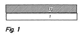
- Fig. 1 illustrates a porous electrode on an electrolyte,
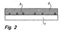
- Fig. 2 shows a porous electrode anchored to an electrolyte by means of a noncovering layer of anchoring particles,
- Fig. 3 illustrate two identical electrodes on an electrolyte, said two electrodes forming a symmetrical cell for characterising the polarisation resistance of the electrodes, and
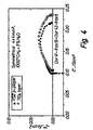
- Fig. 4 shows a Nyquist plot of the impedance of a Ce0.6Gd0.4 O1.6 (=CGO) electrode on a YSZ electrolyte measured with a geometry as shown in Fig. 3, with and without, respectively, a noncovering layer of anchoring particles made of TiO2.
-
- The invention is illustrated below by means of Examples:
- The symmetrical cells of Fig. 3 are manufactured as follows.A noncovering layer of TiO2 anchoring particles is sintered onto electrolyte foils, viz. YSZ with 8% by mole of Y2O3, = 8YSZ, said noncovering layer of TiO2 anchoring particles being produced by ball milling of TiO2-agglomerates and isolation of a particle fraction of approximately 1 to 5 µm through sedimentation.
- The foils with anchoring particles sprayed thereon are sintered at 1150°C/2h, and subsequently a 20 µm porous Ce0.6Gd0.4O1.8 (=CGO) electrode is applied in two layers and two sinterings at 1100°C/2h. Subsequently, the two symmetrical cells are frozen in water on a freezing surface and cut into test pieces of 4 times 4 mm2. The test pieces are provided with an Au/CG4 current collector and mounted between Pt grids and auxiliary cells in such a manner that the polarisation resistance Rp of the electrodes can be measured without being affected by diffusion outside the porous electrode structure. The electrodes are characterised by impedance spectroscopy at 700 to 1000°C in hydrogen with 3% water while subjected to an AC amplitude of 14 mV RMS about an open voltage (ocv).
- For comparison, corresponding test pieces are produced with 8YSZ anchoring particles sintered thereon at 1400°C/2h and tested under the same conditions.
- Area-corrected impedance spectra for the two types of electrodes are indicated in the Nyquist-plot in Fig. 4, where the distance between the intersections of the curve and the abscissa indicates the area-specific polarisation resistance Pp.
- It appears that the polarization resistance Pp is not significantly increased by the presence of the TiO2 layer. The change is within the degree of accuracy.
- Optical pictures are taken of the TiO2 layer after the sintering. The particle layer covers approximately 10% of the surface and the particle size is approximately 2 µm. A few agglomerates of 5 to 7 µm appear.
- The attachment of the TiO2 layer is very strong. It is not possible to remove the layer by means of a scalpel, but the upper portions of large agglomerates are, however, removed. Reference pieces with 8YSZ anchoring particles do not present quite the same attachment. Here the particles are easily removed by scraping with a nail.
- The Redox stability was examined by subjecting cell fragments (20 times 45 mm2) with TiO2 anchoring particles to a heating to 850°C in air, shifting to 9% dry H2 for two hours and finally cooling in air to room temperature. No delamination nor descaling of the electrodes appear.
- The symmetrical cells of Fig. 3 are manufactured as follows.A noncovering layer of TiO2 anchoring particles is sprayed onto sintered 8YSZ electrolyte foils, said layer of TiO2 anchoring particles being produced by ball milling of TiO2-agglomerates and isolation of a particle fraction of approximately 5 to 20 µm through sedimentation.
- The foils with anchoring particles sprayed thereon are sintered at 1150°C/2h, and subsequently a 20 µm porous composite LSM/8YSZ electrode is applied in two layers, and two sinterings at 1100°C/2h are carried out. Subsequently, the two symmetrical cells are frozen in water on a freezing surface and cut into test pieces of 4 times 4 mm2. The test pieces are provided with an LSM current collector and mounted between Pt grid. The electrodes are characterised by impedance spectroscopy at 700 to 1000°C in air while subjected to an AC amplitude of 14 mV RMS about an open voltage (ocv).
- For comparison, corresponding test pieces are produced without anchoring particles and tested under the same conditions.
- Area-corrected impedance spectra for the two types of electrodes can be indicated in a Nyquist-plot, where the distance between the intersections of the curve and the abscissa indicates the area-specific polarisation resistance.
- The polarization resistance is not significantly increased, viz. approximately 10%, by the presence of the TiO2 layer. The change is found at 850°C.
- Optical pictures of the TiO2 layer are taken after the sintering. The particle layer covers approximately 15% o the surface and the particle size is approximately 2 to 4 µm.
Claims (3)
- A method of manufacturing an electrochemical cell comprising an electrolyte (1) and a porous electrode (2), characterised by a noncovering layer of particles (3) being applied and sintered onto the electrolyte (1), said particles (3) being of another composition than said electrolyte (1), whereafter a sintering is carried out, and the electrode (2) is applied and is attached to the electrolyte (1) by means of the particles (3).
- A method as claimed in claim 1, characterised by the noncovering layer of particles (3) between the electrolyte (1) and the electrode (2) being substantially composed of TiO2, optionally doped TiO2.
- A method as claimed in claim 1, characterised by said noncovering layer of particles (3) between the electrolyte (1) and the electrode (2) being composed of a material of substantially the same composition as said electrode (2) and being sintered at a temperature higher than the temperature at which the following sintering onto the electrode (2) is carried out.
Applications Claiming Priority (3)
| Application Number | Priority Date | Filing Date | Title |
|---|---|---|---|
| DK200001482 | 2000-10-05 | ||
| DK200001482A DK200001482A (en) | 2000-10-05 | 2000-10-05 | Electrochemical cell and process for making same. |
| PCT/DK2001/000629 WO2002029919A1 (en) | 2000-10-05 | 2001-10-02 | Electrochemical cell and a method for the manufacture thereof |
Publications (2)
| Publication Number | Publication Date |
|---|---|
| EP1323206A1 EP1323206A1 (en) | 2003-07-02 |
| EP1323206B1 true EP1323206B1 (en) | 2004-09-15 |
Family
ID=8159771
Family Applications (1)
| Application Number | Title | Priority Date | Filing Date |
|---|---|---|---|
| EP01971730A Expired - Lifetime EP1323206B1 (en) | 2000-10-05 | 2001-10-02 | A method of the manufacturing of an electrochemical cell |
Country Status (8)
| Country | Link |
|---|---|
| US (1) | US7482082B2 (en) |
| EP (1) | EP1323206B1 (en) |
| JP (1) | JP4153298B2 (en) |
| AT (1) | ATE276589T1 (en) |
| AU (1) | AU2001291648A1 (en) |
| DE (1) | DE60105625T2 (en) |
| DK (2) | DK200001482A (en) |
| WO (1) | WO2002029919A1 (en) |
Families Citing this family (5)
| Publication number | Priority date | Publication date | Assignee | Title |
|---|---|---|---|---|
| AU2004247229B2 (en) * | 2003-06-09 | 2006-12-14 | Saint-Gobain Ceramics & Plastics, Inc. | Fused zirconia-based solid oxide fuel cell |
| JP4695828B2 (en) * | 2003-11-05 | 2011-06-08 | 本田技研工業株式会社 | Electrolyte / electrode assembly and method for producing the same |
| JP5036521B2 (en) | 2007-12-12 | 2012-09-26 | 株式会社椿本チエイン | Lubricant composition for chain and chain |
| JP6358099B2 (en) * | 2015-01-08 | 2018-07-18 | 株式会社デンソー | Fuel cell single cell and manufacturing method thereof |
| JP6803452B2 (en) * | 2018-12-17 | 2020-12-23 | 日本碍子株式会社 | Electrochemical cell |
Family Cites Families (20)
| Publication number | Priority date | Publication date | Assignee | Title |
|---|---|---|---|---|
| US4490444A (en) * | 1980-12-22 | 1984-12-25 | Westinghouse Electric Corp. | High temperature solid electrolyte fuel cell configurations and interconnections |
| US5028568A (en) | 1989-07-05 | 1991-07-02 | Wisconsin Alumni Research Foundation | Niobium-doped titanium membranes |
| JPH03147264A (en) * | 1989-10-31 | 1991-06-24 | Sanyo Electric Co Ltd | Solid electrolyte fuel cell |
| JPH0795404B2 (en) * | 1990-01-26 | 1995-10-11 | 松下電器産業株式会社 | Solid electrolyte membrane |
| GB9007791D0 (en) | 1990-04-06 | 1990-06-06 | Foss Richard C | High voltage boosted wordline supply charge pump and regulator for dram |
| US5106706A (en) * | 1990-10-18 | 1992-04-21 | Westinghouse Electric Corp. | Oxide modified air electrode surface for high temperature electrochemical cells |
| JPH04190564A (en) * | 1990-11-22 | 1992-07-08 | Tokyo Gas Co Ltd | Manufacture of solid electrolyte fuel cell |
| JP2838344B2 (en) | 1992-10-28 | 1998-12-16 | 三菱電機株式会社 | Semiconductor device |
| JP3267034B2 (en) * | 1993-03-10 | 2002-03-18 | 株式会社村田製作所 | Method for manufacturing solid oxide fuel cell |
| DE4314323C2 (en) * | 1993-04-30 | 1998-01-22 | Siemens Ag | High-temperature fuel cell with an improved solid electrolyte / electrode interface and method for producing a multilayer structure with an improved solid electrolyte / electrode interface |
| JPH07240215A (en) | 1994-02-25 | 1995-09-12 | Mitsubishi Heavy Ind Ltd | Manufacturing method of solid electrolyte fuel cell |
| JP3129131B2 (en) | 1995-02-01 | 2001-01-29 | 日本電気株式会社 | Boost circuit |
| US5726944A (en) | 1996-02-05 | 1998-03-10 | Motorola, Inc. | Voltage regulator for regulating an output voltage from a charge pump and method therefor |
| JPH1012247A (en) * | 1996-06-18 | 1998-01-16 | Murata Mfg Co Ltd | Solid electrolyte fuel cell and manufacture therefor |
| US5818288A (en) | 1996-06-27 | 1998-10-06 | Advanced Micro Devices, Inc. | Charge pump circuit having non-uniform stage capacitance for providing increased rise time and reduced area |
| JPH1173982A (en) | 1997-08-28 | 1999-03-16 | Toto Ltd | Solid electrolyte fuel cell and its manufacture |
| JPH11345619A (en) | 1998-06-03 | 1999-12-14 | Murata Mfg Co Ltd | Solid electrolyte fuel cell |
| JP3293577B2 (en) | 1998-12-15 | 2002-06-17 | 日本電気株式会社 | Charge pump circuit, booster circuit, and semiconductor memory device |
| IT1306964B1 (en) | 1999-01-19 | 2001-10-11 | St Microelectronics Srl | CAPACITIVE BOOSTING CIRCUIT FOR REGULATION OF LINE VOLTAGE READING IN NON-VOLATILE MEMORIES |
| KR100344936B1 (en) * | 1999-10-01 | 2002-07-19 | 한국에너지기술연구원 | Tubular Solid Oxide Fuel Cell supported by Fuel Electrode and Method for the same |
-
2000
- 2000-10-05 DK DK200001482A patent/DK200001482A/en not_active Application Discontinuation
-
2001
- 2001-10-02 WO PCT/DK2001/000629 patent/WO2002029919A1/en not_active Ceased
- 2001-10-02 JP JP2002533424A patent/JP4153298B2/en not_active Expired - Fee Related
- 2001-10-02 EP EP01971730A patent/EP1323206B1/en not_active Expired - Lifetime
- 2001-10-02 AT AT01971730T patent/ATE276589T1/en not_active IP Right Cessation
- 2001-10-02 DK DK01971730T patent/DK1323206T3/en active
- 2001-10-02 DE DE60105625T patent/DE60105625T2/en not_active Expired - Lifetime
- 2001-10-02 AU AU2001291648A patent/AU2001291648A1/en not_active Abandoned
-
2003
- 2003-04-03 US US10/406,515 patent/US7482082B2/en not_active Expired - Fee Related
Also Published As
| Publication number | Publication date |
|---|---|
| WO2002029919A1 (en) | 2002-04-11 |
| JP2004511072A (en) | 2004-04-08 |
| AU2001291648A1 (en) | 2002-04-15 |
| EP1323206A1 (en) | 2003-07-02 |
| DK1323206T3 (en) | 2005-01-24 |
| ATE276589T1 (en) | 2004-10-15 |
| DE60105625T2 (en) | 2005-02-03 |
| DE60105625D1 (en) | 2004-10-21 |
| US7482082B2 (en) | 2009-01-27 |
| JP4153298B2 (en) | 2008-09-24 |
| US20030232249A1 (en) | 2003-12-18 |
| DK200001482A (en) | 2002-04-06 |
Similar Documents
| Publication | Publication Date | Title |
|---|---|---|
| JP4773588B1 (en) | Fuel cell | |
| EP3352274B1 (en) | Metal support type electrochemical element, and method for manufacturing solid oxide type fuel cell and metal support type electrochemical element | |
| EP1768208A2 (en) | High performance anode-supported solid oxide fuel cell | |
| EP0670606A1 (en) | Solid oxide electrolyte fuel cell | |
| JP4773589B1 (en) | Fuel cell | |
| EP0552055B1 (en) | A process for producing solid oxide fuel cells | |
| KR20160048809A (en) | Metal supported solid oxide fuel cell | |
| Kawada et al. | Ceria-zirconia composite electrolyte for solid oxide fuel cells | |
| Primdahl et al. | Effect of nickel oxide/yttria‐stabilized zirconia anode precursor sintering temperature on the properties of solid oxide fuel cells | |
| EP1284519B1 (en) | Solid electrolyte fuel cell and related manufacturing method | |
| Ishihara et al. | Intermediate temperature solid oxide fuel cells using LaGaO3 based oxide film deposited by PLD method | |
| Kariya et al. | Development of a novel cell structure for low-temperature SOFC using porous stainless steel support combined with hydrogen permeable Pd layer and thin film proton conductor | |
| KR101576314B1 (en) | Electrolyte for an inexpensive, electrolyte-supported high-temperature fuel cell having high power and high mechanical strength | |
| JP5809159B2 (en) | ASSEMBLY FOR FUEL CELL AND METHOD FOR PRODUCING THE SAME | |
| US20090232973A1 (en) | Toughened Electrode-Supported Ceramic Fuel Cells and Method for Making | |
| JP3218555B2 (en) | Ceria based solid electrolyte with protective layer | |
| EP1323206B1 (en) | A method of the manufacturing of an electrochemical cell | |
| US20110053045A1 (en) | Solid oxide fuel cell and method of manufacturing the same | |
| Nomura et al. | Fabrication of YSZ electrolyte for intermediate temperature solid oxide fuel cell using electrostatic spray deposition: II–Cell performance | |
| JP3259756B2 (en) | Multilayer solid electrolyte for solid fuel cells | |
| Sun et al. | Fabrication of BaZr0. 1Ce0. 7Y0. 2O3–δ‐Based Proton‐Conducting Solid Oxide Fuel Cells Co‐Fired at 1,150° C | |
| KR20160024879A (en) | High-temperature cell with a porous gas-conducting channel layer | |
| KR20230129626A (en) | Method for manufacturing electrochemical element and electrochemical element | |
| CN118867284A (en) | Oxygen electrode of solid oxide battery and preparation method and repair method thereof, and solid oxide battery | |
| JP3574439B2 (en) | Microstructured electrode with extended three-phase interface by porous ion-conductive ceria membrane coating and method of manufacturing the same |
Legal Events
| Date | Code | Title | Description |
|---|---|---|---|
| PUAI | Public reference made under article 153(3) epc to a published international application that has entered the european phase |
Free format text: ORIGINAL CODE: 0009012 |
|
| 17P | Request for examination filed |
Effective date: 20030403 |
|
| AK | Designated contracting states |
Designated state(s): AT BE CH CY DE DK ES FI FR GB GR IE IT LI LU MC NL PT SE TR |
|
| AX | Request for extension of the european patent |
Extension state: AL LT LV MK RO SI |
|
| 17Q | First examination report despatched |
Effective date: 20031114 |
|
| GRAP | Despatch of communication of intention to grant a patent |
Free format text: ORIGINAL CODE: EPIDOSNIGR1 |
|
| RTI1 | Title (correction) |
Free format text: A METHOD OF THE MANUFACTURING OF AN ELECTROCHEMICAL CELL |
|
| GRAS | Grant fee paid |
Free format text: ORIGINAL CODE: EPIDOSNIGR3 |
|
| GRAA | (expected) grant |
Free format text: ORIGINAL CODE: 0009210 |
|
| AK | Designated contracting states |
Kind code of ref document: B1 Designated state(s): AT BE CH CY DE DK ES FI FR GB GR IE IT LI LU MC NL PT SE TR |
|
| PG25 | Lapsed in a contracting state [announced via postgrant information from national office to epo] |
Ref country code: TR Free format text: LAPSE BECAUSE OF FAILURE TO SUBMIT A TRANSLATION OF THE DESCRIPTION OR TO PAY THE FEE WITHIN THE PRESCRIBED TIME-LIMIT Effective date: 20040915 Ref country code: CY Free format text: LAPSE BECAUSE OF FAILURE TO SUBMIT A TRANSLATION OF THE DESCRIPTION OR TO PAY THE FEE WITHIN THE PRESCRIBED TIME-LIMIT Effective date: 20040915 Ref country code: AT Free format text: LAPSE BECAUSE OF FAILURE TO SUBMIT A TRANSLATION OF THE DESCRIPTION OR TO PAY THE FEE WITHIN THE PRESCRIBED TIME-LIMIT Effective date: 20040915 Ref country code: BE Free format text: LAPSE BECAUSE OF FAILURE TO SUBMIT A TRANSLATION OF THE DESCRIPTION OR TO PAY THE FEE WITHIN THE PRESCRIBED TIME-LIMIT Effective date: 20040915 |
|
| REG | Reference to a national code |
Ref country code: GB Ref legal event code: FG4D Ref country code: CH Ref legal event code: EP |
|
| REG | Reference to a national code |
Ref country code: CH Ref legal event code: NV Representative=s name: ROTTMANN, ZIMMERMANN + PARTNER AG |
|
| PG25 | Lapsed in a contracting state [announced via postgrant information from national office to epo] |
Ref country code: LU Free format text: LAPSE BECAUSE OF NON-PAYMENT OF DUE FEES Effective date: 20041002 |
|
| PG25 | Lapsed in a contracting state [announced via postgrant information from national office to epo] |
Ref country code: IE Free format text: LAPSE BECAUSE OF NON-PAYMENT OF DUE FEES Effective date: 20041004 |
|
| REG | Reference to a national code |
Ref country code: IE Ref legal event code: FG4D |
|
| REF | Corresponds to: |
Ref document number: 60105625 Country of ref document: DE Date of ref document: 20041021 Kind code of ref document: P |
|
| PG25 | Lapsed in a contracting state [announced via postgrant information from national office to epo] |
Ref country code: MC Free format text: LAPSE BECAUSE OF NON-PAYMENT OF DUE FEES Effective date: 20041031 |
|
| PG25 | Lapsed in a contracting state [announced via postgrant information from national office to epo] |
Ref country code: GR Free format text: LAPSE BECAUSE OF FAILURE TO SUBMIT A TRANSLATION OF THE DESCRIPTION OR TO PAY THE FEE WITHIN THE PRESCRIBED TIME-LIMIT Effective date: 20041215 |
|
| PG25 | Lapsed in a contracting state [announced via postgrant information from national office to epo] |
Ref country code: ES Free format text: LAPSE BECAUSE OF FAILURE TO SUBMIT A TRANSLATION OF THE DESCRIPTION OR TO PAY THE FEE WITHIN THE PRESCRIBED TIME-LIMIT Effective date: 20041226 |
|
| REG | Reference to a national code |
Ref country code: SE Ref legal event code: TRGR |
|
| REG | Reference to a national code |
Ref country code: DK Ref legal event code: T3 |
|
| ET | Fr: translation filed | ||
| REG | Reference to a national code |
Ref country code: IE Ref legal event code: MM4A |
|
| PLBE | No opposition filed within time limit |
Free format text: ORIGINAL CODE: 0009261 |
|
| STAA | Information on the status of an ep patent application or granted ep patent |
Free format text: STATUS: NO OPPOSITION FILED WITHIN TIME LIMIT |
|
| 26N | No opposition filed |
Effective date: 20050616 |
|
| REG | Reference to a national code |
Ref country code: GB Ref legal event code: 732E |
|
| REG | Reference to a national code |
Ref country code: CH Ref legal event code: PUE Owner name: DANMARKS TEKNISKE UNIVERSITET Free format text: FORSKNINGSCENTER RISO#RISO NATIONAL LABORATORY, P.O. BOX 49#4000 ROSKILDE (DK) -TRANSFER TO- DANMARKS TEKNISKE UNIVERSITET#ANKER ENGELUNDSVEJ 1 DTU-BYGNING 101 A#2800 KGS. LYNGBY (DK) |
|
| NLS | Nl: assignments of ep-patents |
Owner name: DANMARKS TEKNISKE UNIVERSITET Effective date: 20070301 |
|
| REG | Reference to a national code |
Ref country code: FR Ref legal event code: TP |
|
| PG25 | Lapsed in a contracting state [announced via postgrant information from national office to epo] |
Ref country code: PT Free format text: LAPSE BECAUSE OF NON-PAYMENT OF DUE FEES Effective date: 20050215 |
|
| REG | Reference to a national code |
Ref country code: CH Ref legal event code: PFA Owner name: DANMARKS TEKNISKE UNIVERSITET Free format text: DANMARKS TEKNISKE UNIVERSITET#ANKER ENGELUNDSVEJ 1 DTU-BYGNING 101 A#2800 KGS. LYNGBY (DK) -TRANSFER TO- DANMARKS TEKNISKE UNIVERSITET#ANKER ENGELUNDSVEJ 1 DTU-BYGNING 101 A#2800 KGS. LYNGBY (DK) |
|
| PGFP | Annual fee paid to national office [announced via postgrant information from national office to epo] |
Ref country code: DK Payment date: 20141027 Year of fee payment: 14 |
|
| PGFP | Annual fee paid to national office [announced via postgrant information from national office to epo] |
Ref country code: SE Payment date: 20141029 Year of fee payment: 14 Ref country code: FI Payment date: 20141029 Year of fee payment: 14 Ref country code: DE Payment date: 20141029 Year of fee payment: 14 Ref country code: GB Payment date: 20141027 Year of fee payment: 14 Ref country code: CH Payment date: 20141027 Year of fee payment: 14 Ref country code: FR Payment date: 20141017 Year of fee payment: 14 |
|
| PGFP | Annual fee paid to national office [announced via postgrant information from national office to epo] |
Ref country code: NL Payment date: 20141026 Year of fee payment: 14 |
|
| PGFP | Annual fee paid to national office [announced via postgrant information from national office to epo] |
Ref country code: IT Payment date: 20141027 Year of fee payment: 14 |
|
| REG | Reference to a national code |
Ref country code: DE Ref legal event code: R119 Ref document number: 60105625 Country of ref document: DE |
|
| REG | Reference to a national code |
Ref country code: DK Ref legal event code: EBP Effective date: 20151031 |
|
| REG | Reference to a national code |
Ref country code: SE Ref legal event code: EUG Ref country code: CH Ref legal event code: PL |
|
| GBPC | Gb: european patent ceased through non-payment of renewal fee |
Effective date: 20151002 |
|
| REG | Reference to a national code |
Ref country code: NL Ref legal event code: MM Effective date: 20151101 |
|
| PG25 | Lapsed in a contracting state [announced via postgrant information from national office to epo] |
Ref country code: LI Free format text: LAPSE BECAUSE OF NON-PAYMENT OF DUE FEES Effective date: 20151031 Ref country code: GB Free format text: LAPSE BECAUSE OF NON-PAYMENT OF DUE FEES Effective date: 20151002 Ref country code: DE Free format text: LAPSE BECAUSE OF NON-PAYMENT OF DUE FEES Effective date: 20160503 Ref country code: CH Free format text: LAPSE BECAUSE OF NON-PAYMENT OF DUE FEES Effective date: 20151031 Ref country code: IT Free format text: LAPSE BECAUSE OF NON-PAYMENT OF DUE FEES Effective date: 20151002 |
|
| REG | Reference to a national code |
Ref country code: FR Ref legal event code: ST Effective date: 20160630 |
|
| PG25 | Lapsed in a contracting state [announced via postgrant information from national office to epo] |
Ref country code: NL Free format text: LAPSE BECAUSE OF NON-PAYMENT OF DUE FEES Effective date: 20151101 Ref country code: FR Free format text: LAPSE BECAUSE OF NON-PAYMENT OF DUE FEES Effective date: 20151102 Ref country code: SE Free format text: LAPSE BECAUSE OF NON-PAYMENT OF DUE FEES Effective date: 20151003 |
|
| PG25 | Lapsed in a contracting state [announced via postgrant information from national office to epo] |
Ref country code: DK Free format text: LAPSE BECAUSE OF NON-PAYMENT OF DUE FEES Effective date: 20151031 |
|
| PG25 | Lapsed in a contracting state [announced via postgrant information from national office to epo] |
Ref country code: FI Free format text: LAPSE BECAUSE OF NON-PAYMENT OF DUE FEES Effective date: 20151002 |