EP1322909B2 - Co-ordinate measuring device - Google Patents
Co-ordinate measuring device Download PDFInfo
- Publication number
- EP1322909B2 EP1322909B2 EP01969709.3A EP01969709A EP1322909B2 EP 1322909 B2 EP1322909 B2 EP 1322909B2 EP 01969709 A EP01969709 A EP 01969709A EP 1322909 B2 EP1322909 B2 EP 1322909B2
- Authority
- EP
- European Patent Office
- Prior art keywords
- rotary joint
- encoder
- coordinate measuring
- measuring machine
- drive
- Prior art date
- Legal status (The legal status is an assumption and is not a legal conclusion. Google has not performed a legal analysis and makes no representation as to the accuracy of the status listed.)
- Expired - Lifetime
Links
- 239000000523 sample Substances 0.000 claims description 38
- 238000011156 evaluation Methods 0.000 claims description 16
- 238000000034 method Methods 0.000 claims description 6
- 230000000712 assembly Effects 0.000 claims 1
- 238000000429 assembly Methods 0.000 claims 1
- 230000003287 optical effect Effects 0.000 description 8
- 238000005259 measurement Methods 0.000 description 7
- 230000008859 change Effects 0.000 description 3
- 238000004891 communication Methods 0.000 description 3
- 230000005291 magnetic effect Effects 0.000 description 3
- 230000008569 process Effects 0.000 description 3
- 230000008901 benefit Effects 0.000 description 2
- 238000010276 construction Methods 0.000 description 2
- 230000005294 ferromagnetic effect Effects 0.000 description 2
- 230000007246 mechanism Effects 0.000 description 2
- 238000011161 development Methods 0.000 description 1
- 230000018109 developmental process Effects 0.000 description 1
- 238000006073 displacement reaction Methods 0.000 description 1
- 230000009467 reduction Effects 0.000 description 1
Images


Classifications
-
- G—PHYSICS
- G01—MEASURING; TESTING
- G01B—MEASURING LENGTH, THICKNESS OR SIMILAR LINEAR DIMENSIONS; MEASURING ANGLES; MEASURING AREAS; MEASURING IRREGULARITIES OF SURFACES OR CONTOURS
- G01B11/00—Measuring arrangements characterised by the use of optical techniques
- G01B11/002—Measuring arrangements characterised by the use of optical techniques for measuring two or more coordinates
- G01B11/005—Measuring arrangements characterised by the use of optical techniques for measuring two or more coordinates coordinate measuring machines
- G01B11/007—Measuring arrangements characterised by the use of optical techniques for measuring two or more coordinates coordinate measuring machines feeler heads therefor
-
- G—PHYSICS
- G01—MEASURING; TESTING
- G01B—MEASURING LENGTH, THICKNESS OR SIMILAR LINEAR DIMENSIONS; MEASURING ANGLES; MEASURING AREAS; MEASURING IRREGULARITIES OF SURFACES OR CONTOURS
- G01B21/00—Measuring arrangements or details thereof, where the measuring technique is not covered by the other groups of this subclass, unspecified or not relevant
- G01B21/02—Measuring arrangements or details thereof, where the measuring technique is not covered by the other groups of this subclass, unspecified or not relevant for measuring length, width, or thickness
- G01B21/04—Measuring arrangements or details thereof, where the measuring technique is not covered by the other groups of this subclass, unspecified or not relevant for measuring length, width, or thickness by measuring coordinates of points
- G01B21/047—Accessories, e.g. for positioning, for tool-setting, for measuring probes
Definitions
- the invention relates to a coordinate measuring machine with a receptacle for automatically replaceable attachment of a sensor.
- Such a coordinate measuring machine is for example ours U.S. Patent 4,888,877 and the corresponding European patent 0 317 967 B1 known.
- a so-called rotary-pivot device is attached to which in turn a probe is attached.
- the rotary-pivoting device in this case has two successively arranged, motor-driven rotary joints with mutually perpendicular axes of rotation, via which the probe can be moved in different rotational positions.
- the probe is in this case attached via a corresponding receptacle interchangeable with the rotary-pivoting device and can therefore be automatically stored during a measurement process in a dedicated magazine and exchanged for a new probe.
- Such a rotary-pivoting device has rendered excellent services in the past and in particular the fast and easy measurement of complex geometries, such as, for example, space-inclined holes.
- optical laser triangulation probes have been known for a long time which can measure the distance to the workpiece surface along a line.
- a laser beam is fan-shaped and observed at an angle through a video camera. If the curtain-like fanned laser beam impinges on a workpiece surface, a line-like pattern is thereby produced, wherein the distance to the workpiece surface can be determined from the position of the line-like pattern in the video image.
- the plane of the laser curtain should be perpendicular to the edge.
- the rotary-pivoting device is extended by an additional pivot.
- our invention has the object to provide a coordinate measuring machine mentioned above, with the different measurement tasks can be easily handled.
- the independent claim 8 also shows a particularly adapted method, with which the automatic change of a motor-driven rotary joint or the motor-driven linear adjustment can be operated particularly advantageous, as we will explain in more detail below.
- the basic idea of our invention here is to see that the motor-driven rotary joint and / or the motor-driven linear adjustment, via which the probe rotates about an axis and / or can be adjusted in one direction automatically replaceable on the coordinate measuring machine can be attached.
- the receptacle for interchangeable attachment of the sensor can, as described above, be provided on a rotary pivoting device.
- the recording can just as well be arranged directly on the measuring arm, which can be moved in the three coordinate directions relative to the workpiece to be measured.
- the rotary joint or the linear adjustment itself also has a corresponding receptacle for mounting a sensor.
- different elements of the sensors can be assembled according to the modular principle.
- a hinge can be attached to a receptacle of the measuring arm.
- a linear adjustment can be attached to the rotary joint via the receptacle contained therein, wherein in turn a probe can be attached to the receptacle of the linear adjustment.
- a drive assembly should be provided herein, which has a drive, an angle encoder or linear encoder and a position control loop, so that the hinge and / or the linear adjustment can automatically move to a desired position.
- a drive assembly which has a drive, an angle encoder or linear encoder and a position control loop, so that the hinge and / or the linear adjustment can automatically move to a desired position.
- the position control loop of the drive module should be integrated into the respective control and evaluation unit of the coordinate measuring machine. This makes it possible to use the relevant rotary joint and / or the linear adjustment as separate axes for moving the probe head.
- the angle encoder and / or the linear encoder of the drive module advantageously has both a relative encoder and an absolute encoder.
- the absolute angle of rotation of the rotary joint or the position of the linear adjustment can be determined at any time.
- the drive assembly thereby operable so that after the replacement of at least parts of the sensor in the recording automatically a reference position of the rotary joint and / or the linear adjustment is determined, which is usually determined by a reference mark a Relativcoders.
- the rotary joint or the linear adjustment can be positioned using the signals of the absolute encoder in the vicinity of the reference position of the relative encoder.
- the drive for the rotary joint can particularly advantageously comprise a worm gear. As a result, a largely vibration-free rotation of the rotary joint is made possible.
- the rotatable part of the rotary joint should be rotatably supported particularly advantageous over two spaced-apart rotary bearing. This results in a particularly high rigidity of the rotary joint also transversely to the axis of rotation, which is particularly important when the sensor comprises several successively arranged elements.
- FIG. 1 shows a so-called stator coordinate measuring machine in a perspective view with a sensor according to the invention (5), comprising an optical, two-dimensionally measuring probe (9) and a swivel joint (8) on a recording of a rotary-pivot unit (13) with two hinges (6,7) is attached, as further related below Figures 2 will be explained.
- the coordinate measuring apparatus in this case comprises a mechanism (24) via which the sensor system (5) in the coordinate directions (X, Y, Z) can be adjusted.
- This mechanism (24) comprises a stand (2) which can be moved on guides in the direction indicated by the arrow (y) on the measuring table (1).
- a cross slide (3) is displaceably mounted, on which in turn in the direction described by the arrow (x) direction of the measuring arm (4) is displaceably mounted.
- the individual guides in this case scales are associated with corresponding reading heads, so that in all three coordinate directions (x, y, z), the respective position of the sensor (5) can be determined.
- the coordinate measuring machine here by way of example an evaluation computer (21), which serves to create Meßab connectivityn and for the evaluation of the measured data, and a controller (22), the control of the drives and the recording of the measured data serves.
- Evaluation computer (21) and control (22) of the control and evaluation unit (23) are interconnected via a bus.
- a magazine (73) with different magazine locations is provided at the edge of the measuring range, in which different sensors or individual elements for assembling a sensor, such as probes, hinges and / or linear adjustments lie.
- the sensor (5) can be stored in an empty magazine space and a new sensor from another magazine location are recorded.
- a sub-element of the new sensors such as a rotary joint or a linear adjustment can be attached from a new magazine location, this sub-element itself also has a receptacle over which a further sub-element, such as a probe is attached.
- FIG. 1 shows the sensor system (5) in a perspective view.
- the sensor (5) in addition to the optical probe (9) in addition to a rotary joint (8), which in the recording of a rotary-swivel unit (13) is attached to the measuring arm (4) of the coordinate and defines a rotation axis (a c .).
- the optical probe (9) is in this case a two-dimensional measuring laser triangulation probe, in which a laser beam is fan-shaped to a plane (10). This results in a linear pattern (11) on the workpiece, which is observed at an angle through a video camera also located in the optical probe. From the position of the linear pattern (11) in the video image, the distance to the workpiece, here a calibration ball (12) can be determined.
- the rotary pivot unit (13) in this case has two rotary joints (6,7), each defining two further axes of rotation (a a , a b ), wherein the axis of rotation (a b ) of the rotary joint (7) perpendicular to the axis of rotation (a a ) of the rotary joint (6) and the axis of rotation (a c ) of the rotary joint (8) of the sensor (5) in turn is perpendicular to the axis of rotation (a b ) of the rotary joint (7) of the rotary pivot unit.
- the probe (9) on the pivot joints (6 and 7) of the rotary-pivot unit (13) can be adjusted as desired in space.
- the probe (5) and thus the plane (10) of the fanned laser beam are rotated so that the plane (10) can always be set perpendicular to an optionally scanned edge.
- the rotary-pivot unit (13) used in this embodiment is a rotary-pivot unit, such as in the U.S. Patent 4,888,877 and the corresponding European patent 0 317 967 is shown.
- the sensor (5) with the third rotary joint (8) and the optical probe (9) is received via the receptacle located thereon.
- FIG. 3a is the actual recording (28a) to see how it is provided in the rotary-pivoting device (13).
- the receptacle has three pairs of balls (29a, 29b, 30a, 30b, 31a, 31b). Between the pairs of balls there are contact surfaces of which only by way of example two with the reference numerals (32a, 32b) are designated.
- an electromagnetically operated tensioning device (65) Central in the middle is also an electromagnetically operated tensioning device (65), with the different magnetic fields can be generated.
- the receptacle (28a) acts on a rotary joint (8) fixed plate (28b) together, the three cylinders (33,34,35) has.
- a plurality of resilient contact pins are provided, of which purely by way of example two contact pins with the reference numerals (36a, 36b) have been designated.
- a ferromagnetic component (66) In the center of the plate (28b) is a ferromagnetic component (66).
- the receptacle (28a) is now moved in the vicinity of the plate (28b), ie to the magazine (73), in the swivel joint (8) with the plate (28b) is located, and generates such a large magnetic field via the electromagnetically operated clamping device (65) so that the ferromagnetic component (66) of the plate (28b) is attracted and the cylinders (33 , 34, 35) comes to rest on the respectively assigned pair of balls (29a, 29b; 30a, 30b; 31a, 31b), and the contact pins (36a, 36b) come to rest on the associated contact surfaces (32a, 32b).
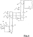
- FIG. 4 shows a completely different embodiment.
- the sensor system herein comprises two linear displacements (15, 19), a pivot (17), and a probe (25) having a stylus (26) and a stylus (27).
- the linear adjustment (15) is attached via a corresponding receptacle (14) on the measuring arm (4) of the coordinate.
- a receptacle (16) can be adjusted in the direction indicated by the whistle (r) direction.
- a rotary joint (17) is replaceably mounted, which allows the rotation of a receptacle (18) about the axis of rotation designated by (w).
- a linear adjustment (19) is fixed, which in turn allows an adjustment of a further receptacle (20) in the direction indicated by the arrow (s) direction.
- a so-called switching probe (25) with a stylus (26) and attached thereto a Tastkugel (27) is attached.
- Such a switching probe (25) operates in such a way that upon touching the probe ball (27) with the workpiece a signal is generated, on the basis of which all scale values are read out and from this a measuring point is calculated.
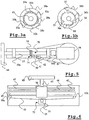
- FIG. 5 shows here purely schematically a hinge in which the cover has been removed, so that the components located inside can be seen.
- the central component is a shaft (37), which is rotatably mounted here via two spaced rotary bearings (38a, 38b).
- the bearing of the shaft on two spaced pivot bearings (38a, 38b) results in a relatively rigid structure of the entire hinge which leads to the reduction of deflections and thus increases the accuracy of measurement.
- a drive (70) In order to rotate the shaft (37), a drive (70) is further provided.
- the drive (70) comprises an electric motor (42) which drives via a belt (41) a worm gear (71) which comprises a worm wheel (40) and a gearwheel (39) cooperating therewith.
- the worm gear of said drive (70) has the advantage compared to previously used drives that rotational movements can be generated largely free of vibration.
- the shaft (37) in turn is rotatably connected via a connector (43) to an assembly (44) in which a first and a second angle encoder are located.
- the first angle encoder is a relative encoder having, for example, an incremental pitch scanned by an optical pickup, the exact position being determined from the number of increments counted from a reference position defined by a reference mark.
- the second angle encoder is an absolute encoder with which absolute angles can be measured. To determine the absolute angle, for example, digitally encoded information can be provided, which can be scanned by a corresponding head and from which the absolute angular position can be determined.
- the relative encoder with the incremental graduation comprises a reference mark which, after exchanging the rotary joint, has to be run over at a corresponding receptacle in order to determine the predefined reference position. Since swivels usually can not be rotated infinitely, but have a stop for each direction of rotation, so far had to swivel joints, as provided for example in the rotary swivel unit (13), the swivel be manually moved by the operator so that in this case exceeded the reference mark and in this case the reference position can be determined. Due to the absolute encoder, it is now possible to fully automatically position the swivel joint in such a way that the relative encoder is located near the reference mark. From here, an automatic search can then be started in which the reference mark is swept over and thereby automatically the reference position is determined.
- the assembly (44) also has a position controller, which is in connection with the Winkelencodem and the drive and thereby defined rotational angular positions of the pivot can set, as we will see below with reference to FIG. 7 be explained.
- FIG. 6 shows purely schematically the structure of a linear adjustment (15 or 19) according to FIG. 4 , Also, the linear adjustment shown here is shown without housing, so that the components therein are visible.
- the linear adjustment has a carriage (46) which is movably mounted via an air bearing along a guide (49). On the carriage (46), a boom (45) is fixed, to which in turn a receptacle (69) for fixing a probe or a rotary joint or another linear adjustment is attached.
- the carriage (46) can be moved by a drive (72) along the guide (49).
- the drive comprises an electric motor (52) from which two underlying wheels (only the wheel 51 can be seen) can be driven.
- the wheels in this case drive a belt (53), which is guided over deflection rollers (50a, 50b) and connected to the carriage (46).
- One end of the belt (53) is attached to the first wheel (51), while the other end of the belt (53) is attached to the underlying wheel.
- a linear encoder (47) is provided, which operates as a relative encoder and, for example, a scale with an incremental graduation and reference mark (67), and a scanning head for scanning the incremental graduation and the reference mark comprises.
- a second linear encoder (48) is provided, which is formed as an absolute encoder and on which, although only roughly, the distance of the carriage (46) from a reference position can be determined absolutely.
- the linear encoder has a scale on which digitally coded distance information is located and a scanning head via which the distance information can be read out. Furthermore, the linear adjustment also includes in analogy to the hinge according to FIG. 5 a positioner that communicates with both the electric motor (52) and the linear encoders (47 and 48) and thus can adjust a defined position of the carriage (46).
- the determination of the reference position also takes place completely analogous to the rotary joint according to FIG. 5 in that the position controller first positions the carriage (46) in accordance with the measured values of the absolute encoder (48) in the vicinity of the reference mark (67) and then automatically guides the carriage over the reference mark (67) in order to be able to determine the reference position.
- the reference numeral (54) is intended here purely schematically the contact pins (36a, 36b, etc.) of a changeover plate (28b) according to FIG. 3b being represented.
- two of the contact pins for the power supply (57) are provided, while two further pins for digital communication via, for example, a CAN bus (58) are provided with the control and evaluation unit (23) of the coordinate measuring machine.
- the communication can alternatively also take place via the two lines of the power supply, if desired.
- All other contact pins which are summarized here by the reference numeral (64) are available for connecting the probe with the control and evaluation of the coordinate measuring machine.
- the drive assembly in this case has a microprocessor (56), which acts in this embodiment, inter alia, as a position controller and additionally the Communication with the control and evaluation unit (23) of the coordinate measuring machine controls.
- a motor (42) is provided, which is controlled via a drive (59), which in turn is connected to the microprocessor (56). Due to the rotation angle set by the motor (42), the angle encoder (62) supplies signals to a "positioning" unit (60) which determines the current angle of rotation and sends it back to the microprocessor (56).
- control and evaluation unit (23) of the coordinate measuring device via the CAN bus (58) Digital transmitted to a controlled rotational position to the microprocessor (56), wherein the microprocessor (56) then based on the Signal of the unit "positioning" (60), the motor drive (59) and the associated motor (42) controls such that the predetermined rotation angle is set.
- a second angle encoder 63 is provided, which is designed as an absolute encoder and measures the absolute angle of rotation of the rotary joint, even if only in an imprecise manner, the assembly "positioning" (60) determining therefrom the angle of rotation and also reports this to the microprocessor (56).
- the reference position of the angle encoder (62) can be determined automatically after exchanging the rotary joint on the recording of the coordinate measuring machine by the microprocessor (56) based on the measured angular position of the absolute encoder (63) the motor (42) controls such that the angle encoder (62) is moved in the vicinity of the reference mark and then the reference mark is passed over to determine the reference position.
- any other coordinate measuring machine can also be used instead of the stator measuring device shown.
- gantry gauges, bridge gauges, robotic arms with hinges, or coordinate measuring machines can be used in which the gantry can be moved in one or more coordinates.
- Even with the designated probe can be a variety of variants. It may be, for example, optical probes, such as Lasertriangulationstaster or Videotastköpfe or touching Probes, such as switching probes or measuring probes act.
- the recording for interchangeable attachment can of course be designed completely different.
- a mechanical gripper or a vacuum suction cup can also be used.
- a differently designed bearing could be used.
- a first element with a conical recess, a second element with a triangular recess and a third element with one plane could be provided.
- three balls are provided instead of the three cylinders of the associated plate, then these are also statically determined uniquely.
- contactless connections could be used.
- the control and evaluation unit could for example be summarized in a computer.
- the drive assembly in the rotary joint or in the linear drive could be different.
- an analog position controller could be used.
- encoders with magnetic information are also used.
Landscapes
- Physics & Mathematics (AREA)
- General Physics & Mathematics (AREA)
- Length Measuring Devices With Unspecified Measuring Means (AREA)
- A Measuring Device Byusing Mechanical Method (AREA)
Description
Die Erfindung betrifft ein Koordinatenmessgerät mit einer Aufnahme zur automatisch auswechselbaren Befestigung einer Sensorik.The invention relates to a coordinate measuring machine with a receptacle for automatically replaceable attachment of a sensor.
Ein derartiges Koordinatenmessgerät ist beispielsweise aus unserem
Eine derartige Dreh-Schwenkeinrichtung hat in der Vergangenheit hervorragende Dienste geleistet und insbesondere das schnelle und unkomplizierte Vermessen von komplexen Geometrien, wie beispielsweise raumschrägen Bohrungen ermöglicht. Es gibt jedoch Meßaufgaben, die sich trotz der erhöhten Flexibilität nicht lösen lassen. Beispielsweise sind seit längerer Zeit optische Lasertriangulationstaster bekannt, die entlang einer Linie den Abstand zur Werkstückoberfläche messen können. Dazu wird ein Laserstrahl vorhangartig aufgefächert und unter einem Winkel durch eine Videokamera beobachtet. Trifft der vorhangartig aufgefächerte Laserstrahl auf einer Werkstückoberfläche auf, so wird hierdurch ein linienartiges Muster erzeugt, wobei aus der Lage des linienartigen Musters im Videobild der Abstand zur Werkstückoberfläche bestimmt werden kann. Um mit einem solchen Taster Kanten zu vermessen, sollte die Ebene des Laservorhanges senkrecht zur der Kante stehen. Dies ist jedoch nur möglich, wenn die Dreh-Schwenkeinrichtung um ein zusätzliches Drehgelenk erweitert wird. Dies würde jedoch bedeuten, daß speziell für diesen Tastkopf eine neue Dreh-Schwenkeinrichtung mit drei Drehgelenken vorgesehen werden muss, was erheblichen zusätzlichen Aufwand verursacht.Such a rotary-pivoting device has rendered excellent services in the past and in particular the fast and easy measurement of complex geometries, such as, for example, space-inclined holes. However, there are measurement tasks that can not be solved despite the increased flexibility. For example, optical laser triangulation probes have been known for a long time which can measure the distance to the workpiece surface along a line. For this purpose, a laser beam is fan-shaped and observed at an angle through a video camera. If the curtain-like fanned laser beam impinges on a workpiece surface, a line-like pattern is thereby produced, wherein the distance to the workpiece surface can be determined from the position of the line-like pattern in the video image. To measure edges with such a button, the plane of the laser curtain should be perpendicular to the edge. However, this is only possible if the rotary-pivoting device is extended by an additional pivot. However, this would mean that specifically for this probe, a new rotary-pivoting device with three hinges must be provided, causing considerable additional effort.
Hiervon ausgehend liegt unserer Erfindung die Aufgabe zugrunde ein Koordinatenmessgerät oben genannter Art anzugeben, mit dem unterschiedliche Meßaufgaben einfach bewältigt werden können.On this basis, our invention has the object to provide a coordinate measuring machine mentioned above, with the different measurement tasks can be easily handled.
Die Aufgabe wird durch die Merkmale des unabhängigen Anspruches 1 gelöst.The object is solved by the features of
Der unabhängige Anspruch 8 zeigt ferner ein besonders angepaßtes Verfahren, mit dem der automatische Wechsel eines motorisch betriebenen Drehgelenkes oder der motorisch betriebenen Linearverstellung besonders vorteilhaft betrieben werden kann, wie wir dies weiter unten noch detailliert erläutern werden.The
Der Grundgedanke unserer Erfindung ist hierbei darin zusehen, dass das motorisch betriebene Drehgelenk und/oder die motorisch betriebene Linearverstellung, über das der Tastkopf um eine Achse rotiert und/oder in einer Richtung verstellt werden kann automatisch auswechselbar am Koordinatenmessgerät befestigt werden kann.The basic idea of our invention here is to see that the motor-driven rotary joint and / or the motor-driven linear adjustment, via which the probe rotates about an axis and / or can be adjusted in one direction automatically replaceable on the coordinate measuring machine can be attached.
Die Aufnahme zur auswechselbaren Befestigung der Sensorik kann, wie oben beschrieben, an einer Dreh-Schwenkeinrichtung vorgesehen sein. Natürlich kann die Aufnahme genauso gut unmittelbar am Meßarm angeordnet sein, der sich in den drei Koordinatenrichtungen relativ zum zu vermessenden Werkstück bewegen läßt.The receptacle for interchangeable attachment of the sensor can, as described above, be provided on a rotary pivoting device. Of course, the recording can just as well be arranged directly on the measuring arm, which can be moved in the three coordinate directions relative to the workpiece to be measured.
Besonders vorteilhaft weist das Drehgelenk oder die Linearverstellung selber auch eine entsprechende Aufnahme zur Befestigung einer Sensorik auf. In diesem Fall können unterschiedliche Elemente der Sensorik nach dem Baukastenprinzip zusammengesetzt werden. Beispielsweise kann ein Drehgelenk an einer Aufnahme des Messarms befestigt werden. Am Drehgelenk wiederum kann über die hierin enthaltene Aufnahme eine Linearverstellung befestigt werden, wobei wiederum an der Aufnahme der Linearverstellung ein Tastkopf befestigt werden kann.Particularly advantageously, the rotary joint or the linear adjustment itself also has a corresponding receptacle for mounting a sensor. In this case, different elements of the sensors can be assembled according to the modular principle. For example, a hinge can be attached to a receptacle of the measuring arm. In turn, a linear adjustment can be attached to the rotary joint via the receptacle contained therein, wherein in turn a probe can be attached to the receptacle of the linear adjustment.
Da der Wechsel der Elemente automatisiert erfolgen kann, können derartige Elemente im Wechselmagazin vorgesehen werden und während eines Meßablaufes automatisiert zu einer geeigneten Sensorik zusammengesetzt werden.Since the change of elements can be done automatically, such elements can be provided in the removable magazine and automatically assembled during a measurement process to a suitable sensor.
Damit die einzelnen Elemente, also das Drehgelenk und/oder die Linearverstellung besonders vorteilhaft in den Meßablauf eingebunden werden können, sollte hierin eine Antriebsbaugruppe vorgesehen seien, die einen Antrieb, einen Winkelencoder bzw Linearencoder und einen Positionsregelkreis aufweist, sodass das Drehgelenk und/oder die Linearverstellung selbsttätig in eine gewünschte Position verfahren kann. Damit ist lediglich ein Datenaustausch zwischen der Steuer- und Auswerteeinheit des Koordinatenmessgerätes und dem Positionsregelkreis erforderlich, der vorzugsweise über einen digital arbeitenden Bus erfolgen sollte.Thus, the individual elements, so the hinge and / or the linear adjustment can be particularly advantageous involved in the measurement process, a drive assembly should be provided herein, which has a drive, an angle encoder or linear encoder and a position control loop, so that the hinge and / or the linear adjustment can automatically move to a desired position. Thus, only a data exchange between the control and evaluation of the coordinate measuring machine and the position control loop is required, which should preferably be done via a digital bus working.
Der Positionsregelkreis der Antriebsbaugruppe sollte in die jeweilige Steuer- und Auswerteeinheit des Koordinatenmessgerätes eingebunden sein. Hierdurch wird es möglich das betreffende Drehgelenk und/oder die Linearverstellung als eigene Achsen zum Verfahren des Tastkopfes mitzubenutzen.The position control loop of the drive module should be integrated into the respective control and evaluation unit of the coordinate measuring machine. This makes it possible to use the relevant rotary joint and / or the linear adjustment as separate axes for moving the probe head.
Vorteilhaft weist der Winkelencoder und/oder der Linearencoder der Antriebsbaugruppe sowohl einen Relativencoder, wie auch einen Absolutencoder auf. Hierdurch kann jederzeit der absolute Drehwinkel des Drehgelenkes bzw. die Stellung der Linearverstellung festgestellt werden. Insbesondere wird die Antriebsbaugruppe hierdurch so betreibbar, daß nach dem Einwechseln von zumindest Teilen der Sensorik in die Aufnahme automatisch eine Referenzstellung des Drehgelenkes und/oder der Linearverstellung ermittelt wird, die üblicherweise durch eine Referenzmarke eines Relativencoders festgelegt ist. Um diese Referenzstellung des Relativencoders automatisch zu ermitteln, kann das Drehgelenk bzw. die Linearverstellung unter Verwendung der Signale des Absolutencoders in der Nähe der Referenzstellung des Relativencoders positioniert werden. Hierdurch wird es möglich, daß völlig automatisiert nach dem Einwechseln des Drehgelenkes oder der Linearverstellung an der Aufnahme das Drehgelenk oder die Linearverstellung die Stellung überfährt, in der sich die Referenzmarke befindet, um hierdurch die Referenzposition automatisiert zu ermitteln. Für den Fall, dass es sich bei dem an der Aufnahme befestigten Element um ein Drehgelenk handelt, kann der Antrieb für das Drehgelenk besonders vorteilhaft ein Schneckengetriebe umfassen. Hierdurch wird ein weitgehend schwingungfreies Verdrehen des Drehgelenkes ermöglicht.The angle encoder and / or the linear encoder of the drive module advantageously has both a relative encoder and an absolute encoder. As a result, the absolute angle of rotation of the rotary joint or the position of the linear adjustment can be determined at any time. In particular, the drive assembly thereby operable so that after the replacement of at least parts of the sensor in the recording automatically a reference position of the rotary joint and / or the linear adjustment is determined, which is usually determined by a reference mark a Relativcoders. In order to automatically determine this reference position of the relative encoder, the rotary joint or the linear adjustment can be positioned using the signals of the absolute encoder in the vicinity of the reference position of the relative encoder. This makes it possible that completely automatically after the replacement of the rotary joint or the linear adjustment of the recording, the rotary joint or the linear adjustment moves over the position in which the reference mark is, thereby automatically determining the reference position. In the event that the element fastened to the receptacle is a rotary joint, the drive for the rotary joint can particularly advantageously comprise a worm gear. As a result, a largely vibration-free rotation of the rotary joint is made possible.
Das rotierbare Teil des Drehgelenkes sollte besonders vorteilhaft über zwei voneinander beabstandete Drehlager drehbar gelagert sein. Hierdurch ergibt sich eine besonders hohe Steifigkeit des Drehgelenkes auch quer zur Drehachse, was insbesondere dann sehr wichtig ist, wenn die Sensorik mehrere nacheinander angeordnete Elemente umfasst.The rotatable part of the rotary joint should be rotatably supported particularly advantageous over two spaced-apart rotary bearing. This results in a particularly high rigidity of the rotary joint also transversely to the axis of rotation, which is particularly important when the sensor comprises several successively arranged elements.
Weitere Vorteile und Weiterbildungen der Erfindung ergeben sich aus den nachfolgend anhand der Figuren beschriebenen Ausführungsbeispielen. Hierin zeigen:
- Figur 1:
- ein Koordinatenmeßgerät mit einer erfindungsgemäßen Sensorik (5), die an einer Aufnahme einer Dreh-Schwenkeinheit (13) am Meßarm (4) des Koordinatenmeßgerätes befestigt ist
- Figur 2:
- Sensorik (5) gemäß
Figur 1 - Figur 3a:
- eine Aufnahme (28a) zur auswechselbaren Befestigung eines Tastkopfes, eines Drehgelenkes oder einer Linearverstellung
- Figur 3b:
- ein mit der Aufnahme (28a) zusammenwirkender Wechselteller (28b)
- Figur 4:
- ein rein schematischer Aufbau eines zweiten Ausführungsbeispiels gemäß der Erfindung
- Figur 5:
- schematische Darstellung der mechanischen Komponenten eines motorisch betriebenen Drehgelenkes
- Figur 6:
- schematische Darstellung der mechanischen Komponenten einer motorisch betriebenen Linearverstellung
- Figur 7:
- schematische Darstellung der elektronischen Komponenten der Antriebsbaugruppe eines Drehgelenkes gemäß
Figur 5
- FIG. 1:
- a coordinate measuring machine with a sensor system (5) according to the invention, which is attached to a receptacle of a rotary-pivot unit (13) on the measuring arm (4) of the coordinate
- FIG. 2:
- Sensor (5) according to
FIG. 1 when scanning a calibration ball (12) - FIG. 3a:
- a receptacle (28 a) for interchangeable attachment of a probe, a rotary joint or a linear adjustment
- FIG. 3b:
- a change plate (28b) cooperating with the receptacle (28a)
- FIG. 4:
- a purely schematic construction of a second embodiment according to the invention
- FIG. 5:
- schematic representation of the mechanical components of a motor-driven rotary joint
- FIG. 6:
- schematic representation of the mechanical components of a motor-driven linear adjustment
- FIG. 7:
- schematic representation of the electronic components of the drive assembly of a rotary joint according to
FIG. 5
Das Koordinatenmeßgerät umfaßt hierbei eine Mechanik (24) über die die Sensorik (5) in den Koordinatenrichtungen (X,Y,Z) verstellt werden kann. Diese Mechanik (24) umfaßt einen Ständer (2), der über Führungen in der mit dem Pfeil (y) bezeichneten Richtung auf dem Meßtisch (1) verfahren werden kann. An dem Ständer (2) ist in der mit dem Pfeil (z) bezeichneten Richtung ein Kreuzschieber (3) verschieblich gelagert, an dem wiederum in der mit dem Pfeil (x) beschriebenen Richtung der Meßarm (4) verschieblich gelagert ist.The coordinate measuring apparatus in this case comprises a mechanism (24) via which the sensor system (5) in the coordinate directions (X, Y, Z) can be adjusted. This mechanism (24) comprises a stand (2) which can be moved on guides in the direction indicated by the arrow (y) on the measuring table (1). On the stand (2) in the direction indicated by the arrow (z) direction a cross slide (3) is displaceably mounted, on which in turn in the direction described by the arrow (x) direction of the measuring arm (4) is displaceably mounted.
Den einzelnen Führungen sind hierbei Maßstäbe mit entsprechenden Ableseköpfen zugeordnet, so daß in allen drei Koordinatenrichtungen (x,y,z) die jeweilige Position der Sensorik (5) bestimmt werden kann. Außerdem sind hier nicht näher zu sehende Antriebe vorgesehen, über die der Ständer (2), der Kreuzschieber (3) und der Meßarm (4) in den Koordinatenrichtungen (X,Y,Z) verfahren werden können. Als Steuer- und Auswerteeinheit (23) weist das Koordinatenmeßgerät hier beispielhaft einen Auswerterechner (21) auf, der der Erstellung von Meßabläufen und zur Auswertung der Meßdaten dient, sowie eine Steuerung (22) auf, die der Ansteuerung der Antriebe und der Aufnahme der Meßdaten dient. Auswerterechner (21) und Steuerung (22) der Steuer- und Auswerteeinheit (23) sind über einen Bus miteinander verbunden.The individual guides in this case scales are associated with corresponding reading heads, so that in all three coordinate directions (x, y, z), the respective position of the sensor (5) can be determined. In addition, here are not closer looking drives provided over which the stator (2), the cross slide (3) and the measuring arm (4) in the coordinate directions (X, Y, Z) can be moved. As a control and evaluation unit (23), the coordinate measuring machine here by way of example an evaluation computer (21), which serves to create Meßabläufen and for the evaluation of the measured data, and a controller (22), the control of the drives and the recording of the measured data serves. Evaluation computer (21) and control (22) of the control and evaluation unit (23) are interconnected via a bus.
Des weiteren ist am Rande des Meßbereiches ein Magazin (73) mit unterschiedlichen Magazinplätzen vorgesehen, in dem unterschiedliche Sensoriken oder Einzelelemente zum Zusammenstellen einer Sensorik, wie Tastköpfe, Drehgelenke und/oder Linearverstellungen abliegen. Über die besagte noch weiter unten beschriebene Aufnahme an der Dreh-Schwenkeinheit (13) kann die Sensorik (5) in einem leeren Magazinplatz abgelegt werden und eine neue Sensorik aus einem anderen Magazinplatz aufgenommen werden. Alternativ kann auch aus einem neuen Magazinplatz nur ein Teilelement der neuen Sensorik, wie beispielsweise ein Drehgelenk oder eine Linearverstellung befestigt werden, wobei dieses Teilelement selber ebenfalls eine Aufnahme besitzt, über die ein weiteres Teilelement, wie beispielsweise ein Tastkopf befestigt wird.Furthermore, a magazine (73) with different magazine locations is provided at the edge of the measuring range, in which different sensors or individual elements for assembling a sensor, such as probes, hinges and / or linear adjustments lie. About the above described recording on the rotary-pivot unit (13), the sensor (5) can be stored in an empty magazine space and a new sensor from another magazine location are recorded. Alternatively, only a sub-element of the new sensors, such as a rotary joint or a linear adjustment can be attached from a new magazine location, this sub-element itself also has a receptacle over which a further sub-element, such as a probe is attached.
Mit der Sensorik (5) können hierbei Meßpunkte auf einem in
Wie aus
Die Dreh-Schwenkeinheit (13) weist hierbei zwei Drehgelenke (6,7) auf, die jeweils zwei weitere Drehachsen (aa,ab) definieren, wobei die Drehachse (ab) des Drehgelenkes (7) senkrecht auf die Drehachse (aa) des Drehgelenkes (6) steht und die Drehachse (ac) des Drehgelenkes (8) der Sensorik (5) wiederum senkrecht auf die Drehachse (ab) des Drehgelenkes (7) der Dreh-Schwenkeinheit steht. Somit kann der Tastkopf (9) über die Drehgelenke (6 und 7) der Dreh-Schwenkeinheit (13) beliebig im Raum verstellt werden. Außerdem kann über das Drehgelenk (8) der Sensorik (5) zusätzlich der Tastkopf (5) und mithin die Ebene (10) des aufgefächerten Laserstrahls verdreht werden, sodass die Ebene (10) immer senkrecht zu einer ggf. abzutastenden Kante eingestellt werden kann.The rotary pivot unit (13) in this case has two rotary joints (6,7), each defining two further axes of rotation (a a , a b ), wherein the axis of rotation (a b ) of the rotary joint (7) perpendicular to the axis of rotation (a a ) of the rotary joint (6) and the axis of rotation (a c ) of the rotary joint (8) of the sensor (5) in turn is perpendicular to the axis of rotation (a b ) of the rotary joint (7) of the rotary pivot unit. Thus, the probe (9) on the pivot joints (6 and 7) of the rotary-pivot unit (13) can be adjusted as desired in space. In addition, via the pivot (8) of the sensor (5) in addition the probe (5) and thus the plane (10) of the fanned laser beam are rotated so that the plane (10) can always be set perpendicular to an optionally scanned edge.
Die in diesem Ausführungsbeispiel verwendete Dreh-Schwenkeinheit (13) ist eine Dreh-Schwenkeinheit, wie sie beispielsweise in dem
Eine solche Aufnahme (28a) soll im folgenden anhand der
Wie bereits eingangs ausgeführt, ist die Erfindung aber keineswegs auf das im Zusammenhang mit den
Ein vorteilhafter Aufbau eines Drehgelenkes (8) gemäß
Um die Welle (37) rotieren zu können, ist ferner ein Antrieb (70) vorgesehen. Der Antrieb (70) umfasst einen Elektromotor (42), der über einen Riemen (41) ein Schneckengetriebe (71) antreibt, das ein Schneckenrad (40) und ein hiermit zusammenwirkendes Zahnrad (39) umfasst. Das Schneckengetriebe des besagten Antriebes (70) weist gegenüber bisher verwendeten Antrieben den Vorteil auf, dass Drehbewegungen weitgehend schwingungsfrei erzeugt werden können.In order to rotate the shaft (37), a drive (70) is further provided. The drive (70) comprises an electric motor (42) which drives via a belt (41) a worm gear (71) which comprises a worm wheel (40) and a gearwheel (39) cooperating therewith. The worm gear of said drive (70) has the advantage compared to previously used drives that rotational movements can be generated largely free of vibration.
Die Welle (37) wiederum ist über einen Verbinder (43) mit einer Baugruppe (44) drehbar verbunden, in der sich ein erster und ein zweiter Winkelencoder befinden. Der erste Winkelencoder ist ein Relativencoder, der beispielsweise eine Inkrementalteilung aufweist, die von einem optischen Abtastkopf abgetastet wird, wobei aus der Anzahl der gezählten Inkremente ausgehend von einer Referenzposition, die durch eine Referenzmarke definiert ist, die genaue Position bestimmt wird. Der zweite Winkelencoder hingegen ist ein Absolutencoder, mit dem absolute Winkel gemessen werden können. Zur Feststellung der absoluten Winkel können beispielsweise digital codierte Informationen vorgesehen sein, die von einem entsprechenden Kopf abgetastet werden können und aus denen sich die absolute Winkellage feststellen läßt.The shaft (37) in turn is rotatably connected via a connector (43) to an assembly (44) in which a first and a second angle encoder are located. The first angle encoder is a relative encoder having, for example, an incremental pitch scanned by an optical pickup, the exact position being determined from the number of increments counted from a reference position defined by a reference mark. The second angle encoder, on the other hand, is an absolute encoder with which absolute angles can be measured. To determine the absolute angle, for example, digitally encoded information can be provided, which can be scanned by a corresponding head and from which the absolute angular position can be determined.
Wie bereits mehrfach beschrieben, umfasst der Relativencoder mit der Inkrementalteilung eine Referenzmarke, die nach dem Einwechseln des Drehgelenkes an einer entsprechenden Aufnahme überfahren werden muss, um die vordefinierte Referenzposition festzustellen. Da Drehgelenke üblicherweise nicht unendlich verdreht werden können, sondern für jede Drehrichtung einen Anschlag haben, musste bislang bei Drehgelenken, wie sie beispielsweise in der Dreh-Schwenkeinheit (13) vorgesehen sind, das Drehgelenk vom Bediener manuell so verfahren werden, daß hierbei die Referenzmarke überschritten wird und hierbei die Referenzposition festgestellt werden kann. Durch den Absolutencoder ist es nunmehr möglich vollkommen automatisiert das Drehgelenk so zu positionieren, dass sich der Relativencoder in der Nähe der Referenzmarke befindet. Von hier aus kann dann ein automatischer Suchlauf gestartet werden, bei dem die Referenzmarke überstrichen wird und hierdurch automatisiert die Referenzposition ermittelt wird.As already described several times, the relative encoder with the incremental graduation comprises a reference mark which, after exchanging the rotary joint, has to be run over at a corresponding receptacle in order to determine the predefined reference position. Since swivels usually can not be rotated infinitely, but have a stop for each direction of rotation, so far had to swivel joints, as provided for example in the rotary swivel unit (13), the swivel be manually moved by the operator so that in this case exceeded the reference mark and in this case the reference position can be determined. Due to the absolute encoder, it is now possible to fully automatically position the swivel joint in such a way that the relative encoder is located near the reference mark. From here, an automatic search can then be started in which the reference mark is swept over and thereby automatically the reference position is determined.
Neben dem besagten Relativencoder und dem Absolutencoder befindet sich in der Baugruppe (44) außerdem ein Positionsregler, der mit den Winkelencodem und dem Antrieb in Verbindung steht und hierdurch definierte Drehwinkelstellungen des Drehgelenkes einstellen kann, wie wir dies weiter unten anhand von
Die Ermittlung der Referenzposition erfolgt hierbei ebenfalls vollkommen analog zum Drehgelenk gemäß
Zur Verdeutlichung des elektronischen Aufbaus soll außerdem anhand von
Als zentrales Bauteil weist die Antriebsbaugruppe hierbei einen Mikroprozessor (56) auf, der in diesem Ausführungsbeispiel u. a. als Positionsregler fungiert und zusätzlich die Kommunikation mit der Steuer- und Auswerteeinheit (23) des Koordinatenmessgerätes steuert. Zur Regelung der Position des Drehgelenkes ist, wie bereits oben beschrieben, ein Motor (42) vorgesehen, der über eine Ansteuerung (59) angesteuert wird, die wiederum mit dem Mikroprozessor (56) in Verbindung steht. Aufgrund des durch den Motor (42) eingestellten Drehwinkels liefert der Winkelencoder (62) Signale an eine Einheit "Positionierung" (60), die hieraus den aktuellen Drehwinkel ermittelt und diesen an den Mikroprozessor (56) zurückgemeldet. Über die beschriebene Schaltung ist es nunmehr möglich, dass die Steuer- und Auswerteeinheit (23) des Koordinatenmessgerätes über den CAN-Bus (58) Digital eine anzusteuernde Drehstellung an den Mikroprozessor (56) übermittelt, wobei der Mikroprozessor (56) dann auf Basis des Signals der Einheit "Positionierung" (60) die Motoransteuerung (59) und den hiermit verbundenen Motor (42) derart ansteuert, dass der vorgegebene Drehwinkel eingestellt wird.As a central component, the drive assembly in this case has a microprocessor (56), which acts in this embodiment, inter alia, as a position controller and additionally the Communication with the control and evaluation unit (23) of the coordinate measuring machine controls. To regulate the position of the rotary joint, as already described above, a motor (42) is provided, which is controlled via a drive (59), which in turn is connected to the microprocessor (56). Due to the rotation angle set by the motor (42), the angle encoder (62) supplies signals to a "positioning" unit (60) which determines the current angle of rotation and sends it back to the microprocessor (56). About the described circuit, it is now possible that the control and evaluation unit (23) of the coordinate measuring device via the CAN bus (58) Digital transmitted to a controlled rotational position to the microprocessor (56), wherein the microprocessor (56) then based on the Signal of the unit "positioning" (60), the motor drive (59) and the associated motor (42) controls such that the predetermined rotation angle is set.
Des weiteren ist, wie, bereits oben ausgeführt, ein zweiter Winkelencoder (63) vorgesehen, der als Absolutencoder ausgeführt ist und, wenn auch nur ungenau, den absoluten Drehwinkel des Drehgelenkes mißt, wobei die Baugruppe "Positionierung" (60) hieraus den Drehwinkel bestimmt und diesen ebenfalls an den Mikroprozessor (56) meldet. Über dieses Signal kann, wie bereits oben detailliert ausgeführt, automatisiert nach dem Einwechseln des Drehgelenkes an der Aufnahme des Koordinatenmessgerätes die Referenzstellung des Winkelencoders (62) ermittelt werden, indem der Mikroprozessor (56) auf Basis der gemessenen Winkelstellung des Absolutencoders (63) den Motor (42) derart ansteuert, daß der Winkelencoder (62) in die Nähe der Referenzmarke verfahren wird und danach die Referenzmarke überfahren wird, um die Referenzposition zu ermitteln.Furthermore, as already stated above, a
Selbstverständlich ist die Erfindung in keiner Weise auf die gezeigten Ausführungsbeispiele beschränkt. Beispielsweise kann an Stelle des gezeigten Ständermessgerätes auch jedes beliebige andere Koordinatenmessgerät verwendet werden. Es können beispielsweise Portalmessgeräte, Brückenmessgeräte, Roboterarme mit Drehgelenken oder Koordinatenmessgeräte verwendet werden, bei denen der Meßtisch in einer oder mehreren Koordinaten verschoben werden kann. Auch bei dem bezeichneten Tastkopf kann es sich um unterschiedlichste Varianten handeln. Es kann sich beispielsweise um optische Tastköpfe, wie beispielsweise Lasertriangulationstaster oder Videotastköpfe oder auch um berührende Tastköpfe, wie beispielsweise schaltende Tastköpfe oder messende Tastköpfe handeln. Auch die Aufnahme zur auswechselbaren Befestigung kann selbstverständlich völlig unterschiedlich ausgestaltet sein. Beispielsweise kann an Stelle der elektromagnetischen Spanneinrichtung auch ein mechanischer Greifer oder ein Vakuumsaugnapf verwendet werden. Auch an Stelle des hier gezeigten Dreipunktlagers könnte beispielsweise ein anders ausgestaltetes Lager verwendet werden. Beispielsweise könnten an Stelle der drei paarweise angeordneten Kugeln auch ein erstes Element mit einer kegelförmigen Aussparung, ein zweites Element mit einer Dreieckförmigen Aussparung und ein drittes Element mit einer Ebene vorgesehen werden. Werden anstelle der drei Zylinder des zugehörigen Tellers drei Kugeln vorgesehen, so sind diese hierdurch ebenfalls statisch eindeutig bestimmt. An Stelle der Kontakte könnten beispielsweise kontaktlose Verbindungen verwendet werden. Die Steuer- und Auswerteeinheit könnte beispielsweise in einem Rechner zusammengefaßt sein. Auch die Antriebsbaugruppe im Drehgelenk oder im Linearantrieb könnte unterschiedlich sein. Beispielsweise könnte anstelle anstelle des Mikroprozessors ein analoger Positionsregler verwendet werden. Anstelle der gezeigten Winkelencoder bzw. Linearencoder, bei denen optisch die Informationen abgetastet werden könnten auch Encoder mit Magnetischen Informationen verwendet werden.Of course, the invention is in no way limited to the exemplary embodiments shown. For example, any other coordinate measuring machine can also be used instead of the stator measuring device shown. For example, gantry gauges, bridge gauges, robotic arms with hinges, or coordinate measuring machines can be used in which the gantry can be moved in one or more coordinates. Even with the designated probe can be a variety of variants. It may be, for example, optical probes, such as Lasertriangulationstaster or Videotastköpfe or touching Probes, such as switching probes or measuring probes act. The recording for interchangeable attachment can of course be designed completely different. For example, instead of the electromagnetic tensioning device, a mechanical gripper or a vacuum suction cup can also be used. Also, instead of the three-point bearing shown here, for example, a differently designed bearing could be used. For example, instead of the three balls arranged in pairs, a first element with a conical recess, a second element with a triangular recess and a third element with one plane could be provided. If three balls are provided instead of the three cylinders of the associated plate, then these are also statically determined uniquely. In place of the contacts, for example, contactless connections could be used. The control and evaluation unit could for example be summarized in a computer. The drive assembly in the rotary joint or in the linear drive could be different. For example, instead of the microprocessor, an analog position controller could be used. Instead of the angle encoders or linear encoders shown, in which optically the information could be scanned, encoders with magnetic information are also used.
Claims (8)
- Coordinate measuring machine having a sensor system (5) and having a holder (28a) for the automatically exchangeable fastening of said sensor system (5), whereina) apart from a probe head (9) the sensor system additionally comprises at least a motor-driven rotary joint (8, 17) by means of which the probe head can be rotated about an axis (ac, w), wherein the rotary joint (8) has a drive assembly with a drive (70), an angle encoder (62, 63) and a position controller (56), and wherein the data exchange between the control and evaluation unit (23) of the coordinate measuring machine and the position controller (56) is performed via a digitally operating bus (58) orb) apart from a probe head (9) the sensor system additionally comprises at least a motor-driven linear adjuster (15, 19), by means of which the probe head can be adjusted in a direction (r, s), wherein the linear adjuster (15) has a drive assembly with a drive (72), a linear encoder (47, 48) and a position controller and wherein the data exchange between the control and evaluation unit (23) of the coordinate measuring machine and the position controller is performed via a digitally operating bus orc) apart from a probe head (9) the sensor system additionally comprises at least a motor-driven rotary joint (8, 17), by means of which the probe head can be rotated about an axis (ac, w), and a motor-driven linear adjuster (15, 19), by means of which the probe head can be adjusted in a direction (r, s), wherein the rotary joint (8) has a drive assembly with a drive (70), an angle encoder (62, 63) and a position controller (56) and wherein the data exchange between the control and evaluation unit (23) of the coordinate measuring machine and the position controller (56) is performed via a digitally operating bus (58) and/or the linear adjuster (15) has a drive assembly with a drive (72), a linear encoder (47, 48) and a position controller and wherein the data exchange between the control and evaluation unit (23) of the coordinate measuring machine and the position controller is performed via a digitally operating bus.
- Coordinate measuring machine according to Claim 1, characterized in that the angle encoder and/or the linear encoder of the drive assembly or drive assemblies has or have both a relative encoder (62, 47) and an absolute encoder (63, 48).
- Coordinate measuring machine according to Claim 2, characterized in that the drive assembly can be operated such that after the loading of at least parts of the sensor system (5) into the holder a reference position of the rotary joint and/or of the linear adjuster are/is determined automatically.
- Coordinate measuring machine according to Claim 3, characterized in that the drive assembly can be operated such that for the purpose of finding the reference position (67) the rotary joint is automatically positioned in the vicinity of a reference mark of the relative encoder by using the signals of the absolute encoder (63) and/or the linear adjuster is automatically positioned in the vicinity of a reference mark of the relative encoder by using the signals of the absolute encoder (48).
- Coordinate measuring machine according to Claim 4, characterized in that the drive assembly can, furthermore, be operated such that after the positioning in the vicinity of the reference mark the reference mark is automatically driven over in a search cycle in order to determine the reference position.
- Coordinate measuring machine according to one of Claims 1 to 5, characterized in that the drive (70) for the rotary joint comprises a worm gear drive (71).
- Coordinate measuring machine according to one of Claims 1 to 6 in which the sensor system (5) comprises a rotary joint, characterized in that the rotatable part (37, 68) of the rotary joint is supported such that it can rotate via two rotary bearings (38a, 38b) spaced apart from one another.
- Method for determining the reference position, defined by a reference mark of a relative encoder, of a rotary joint or of a linear adjuster, having the following method steps:- moving the rotary joint or the linear adjuster into a first predefined position corresponding to the signals of an absolute encoder in the vicinity of the reference mark of the relative encoder,- moving the rotary joint or the linear adjuster from this position in the direction of the reference mark, and scanning the reference mark, and- determining the reference position upon scanning the reference mark.
Applications Claiming Priority (7)
| Application Number | Priority Date | Filing Date | Title |
|---|---|---|---|
| DE2000148096 DE10048096A1 (en) | 2000-09-28 | 2000-09-28 | Swivel unit has optical sensor calibration sensor creates coordinate transformations |
| DE10048096 | 2000-09-28 | ||
| DE2000148095 DE10048095A1 (en) | 2000-09-28 | 2000-09-28 | Swivel unit has optical sensor calibration sensor creates coordinate transformations |
| DE10048095 | 2000-09-28 | ||
| DE10131038 | 2001-06-29 | ||
| DE2001131038 DE10131038A1 (en) | 2001-06-29 | 2001-06-29 | Coordinate measuring instrument with reception mounting for automatically exchangeable fixing of sensor system |
| PCT/EP2001/010470 WO2002027270A1 (en) | 2000-09-28 | 2001-09-11 | Co-ordinate measuring device |
Publications (3)
| Publication Number | Publication Date |
|---|---|
| EP1322909A1 EP1322909A1 (en) | 2003-07-02 |
| EP1322909B1 EP1322909B1 (en) | 2010-11-24 |
| EP1322909B2 true EP1322909B2 (en) | 2016-12-21 |
Family
ID=27214087
Family Applications (1)
| Application Number | Title | Priority Date | Filing Date |
|---|---|---|---|
| EP01969709.3A Expired - Lifetime EP1322909B2 (en) | 2000-09-28 | 2001-09-11 | Co-ordinate measuring device |
Country Status (3)
| Country | Link |
|---|---|
| EP (1) | EP1322909B2 (en) |
| DE (1) | DE50115721D1 (en) |
| WO (1) | WO2002027270A1 (en) |
Families Citing this family (15)
| Publication number | Priority date | Publication date | Assignee | Title |
|---|---|---|---|---|
| DE102004002853A1 (en) * | 2004-01-19 | 2005-08-11 | Carl Zeiss Industrielle Messtechnik Gmbh | Mounting device for coordinate measuring machine |
| EP1752851A1 (en) * | 2005-08-12 | 2007-02-14 | Schneeberger Holding AG | Linear guiding system with measuring means |
| GB0617344D0 (en) * | 2006-09-05 | 2006-10-11 | Renishaw Plc | Surface sensing device |
| US8006399B2 (en) | 2006-09-05 | 2011-08-30 | Renishaw Plc | Surface sensing device |
| DE102007018444C5 (en) * | 2007-04-19 | 2011-02-17 | Carl Mahr Holding Gmbh | Stylus measuring device with stylus magazine for surface and contour measurement |
| JP2009053184A (en) * | 2007-07-30 | 2009-03-12 | Hexagon Metrology Kk | Rotary unit for noncontact sensor and rotary device for noncontact sensor |
| WO2010008730A2 (en) * | 2008-06-17 | 2010-01-21 | Vetco Gray, Inc. | Valve body seat pocket inspection tool |
| US8087181B2 (en) * | 2008-12-26 | 2012-01-03 | Vetco Gray Inc. | Valve body seat pocket inspection tool |
| DE102012007183B4 (en) | 2011-04-28 | 2022-06-02 | Jenoptik Industrial Metrology Germany Gmbh | Measuring device with a changing device for changing measuring bodies |
| DE202013012759U1 (en) | 2013-01-30 | 2019-04-23 | Jenoptik Industrial Metrology Germany Gmbh | Sensing body support assembly |
| DE202014101900U1 (en) | 2014-04-23 | 2014-05-05 | Breitmeier Messtechnik Gmbh | Manipulator for spatial orientation of a miniature roughness meter |
| JP6424969B2 (en) * | 2015-12-11 | 2018-11-21 | 株式会社村田製作所 | Toner bottle |
| US10352340B2 (en) | 2016-03-16 | 2019-07-16 | Hexagon Metrology, Inc. | Probe clips for a coordinate measuring machine |
| DE102018103420A1 (en) | 2018-02-15 | 2019-08-22 | Jenoptik Industrial Metrology Germany Gmbh | Measuring instrument for surface or contour measurement |
| EP4086684B1 (en) | 2021-05-07 | 2024-10-09 | Carl Zeiss Meditec AG | Optical system and method for operating an optical system |
Citations (6)
| Publication number | Priority date | Publication date | Assignee | Title |
|---|---|---|---|---|
| DE2416212A1 (en) † | 1973-05-14 | 1974-11-28 | Contraves Ag | LENGTH AND / OR ANGLE MEASURING DEVICE |
| US4637119A (en) † | 1983-06-03 | 1987-01-20 | Carl-Zeiss-Stiftung, Heidenheim/Brenz | Chucking device for interchangeable holding of probe pins in a coordinate-measuring instrument |
| DE3711644A1 (en) † | 1987-04-06 | 1989-01-12 | Mitutoyo Corp | METHOD AND DEVICE FOR MEASURING SPATIAL COORDINATES |
| US5214426A (en) † | 1988-07-12 | 1993-05-25 | Furuno Electric Company, Limited | Rotary encoder having absolute angle patterns and relative angle patterns |
| US5794356A (en) † | 1993-02-23 | 1998-08-18 | Faro Technologies, Inc. | Three dimensional coordinate measuring apparatus |
| EP1010967A2 (en) † | 1998-12-16 | 2000-06-21 | Dr. Johannes Heidenhain GmbH | Encoder for providing incremental and absolute position data |
Family Cites Families (4)
| Publication number | Priority date | Publication date | Assignee | Title |
|---|---|---|---|---|
| DE3740070A1 (en) * | 1987-11-26 | 1989-06-08 | Zeiss Carl Fa | TURN SLEWING DEVICE FOR TEST COOKING OF COORDINATE MEASURING DEVICES |
| DE4326551C2 (en) * | 1993-08-07 | 1997-04-17 | Heidenhain Gmbh Dr Johannes | Calibration procedure for determining and compensating for different contact force ratios in multi-coordinate touch probes |
| AU7722596A (en) * | 1995-11-14 | 1997-06-05 | Kam C. Lau | On-machine ballbar system and method for using the same |
| DE19639780A1 (en) * | 1996-09-27 | 1998-04-02 | Leitz Brown & Sharpe Mestechni | Combined optical and mechanical measuring instrument for workpieces |
-
2001
- 2001-09-11 EP EP01969709.3A patent/EP1322909B2/en not_active Expired - Lifetime
- 2001-09-11 DE DE50115721T patent/DE50115721D1/en not_active Expired - Lifetime
- 2001-09-11 WO PCT/EP2001/010470 patent/WO2002027270A1/en not_active Ceased
Patent Citations (6)
| Publication number | Priority date | Publication date | Assignee | Title |
|---|---|---|---|---|
| DE2416212A1 (en) † | 1973-05-14 | 1974-11-28 | Contraves Ag | LENGTH AND / OR ANGLE MEASURING DEVICE |
| US4637119A (en) † | 1983-06-03 | 1987-01-20 | Carl-Zeiss-Stiftung, Heidenheim/Brenz | Chucking device for interchangeable holding of probe pins in a coordinate-measuring instrument |
| DE3711644A1 (en) † | 1987-04-06 | 1989-01-12 | Mitutoyo Corp | METHOD AND DEVICE FOR MEASURING SPATIAL COORDINATES |
| US5214426A (en) † | 1988-07-12 | 1993-05-25 | Furuno Electric Company, Limited | Rotary encoder having absolute angle patterns and relative angle patterns |
| US5794356A (en) † | 1993-02-23 | 1998-08-18 | Faro Technologies, Inc. | Three dimensional coordinate measuring apparatus |
| EP1010967A2 (en) † | 1998-12-16 | 2000-06-21 | Dr. Johannes Heidenhain GmbH | Encoder for providing incremental and absolute position data |
Also Published As
| Publication number | Publication date |
|---|---|
| EP1322909B1 (en) | 2010-11-24 |
| EP1322909A1 (en) | 2003-07-02 |
| WO2002027270A1 (en) | 2002-04-04 |
| DE50115721D1 (en) | 2011-01-05 |
Similar Documents
| Publication | Publication Date | Title |
|---|---|---|
| EP1322909B2 (en) | Co-ordinate measuring device | |
| EP0703517B1 (en) | Procedure for measuring of workpieces with a handguided coordinate measuring device | |
| EP0317967B1 (en) | Rotation-deflection arrangement for the feeler heads of coordinate-measuring devices | |
| EP1657524B1 (en) | Method and apparatus for the 3D measurement of dental models and a slidable plate for the same | |
| DE4495551C2 (en) | Z-axis drive for a machine tool | |
| DE3789875T2 (en) | Metrological apparatus. | |
| EP0418203A1 (en) | Vertical/horizontal measuring apparatus and method for operation of same | |
| DE69000140T2 (en) | GRINDING PROCESS WITH MEASUREMENT OF A SHAPED GRINDING WHEEL AND MACHINE TO CARRY OUT IT. | |
| DE102017103938A1 (en) | Device for measuring the roughness of a workpiece surface | |
| DE10052206B4 (en) | A surface texture measuring apparatus, leveling apparatus for a surface texture measuring apparatus, and a method for orienting a workpiece of a surface texture measuring apparatus | |
| DE4207201A1 (en) | LEVELING METHOD AND DEVICE | |
| WO2016015775A1 (en) | Scanning head for a coordinate measuring device | |
| DE19604354A1 (en) | Process for the coordinate measurement of workpieces on processing machines | |
| DE69927597T2 (en) | Method and device for folding angle measurement of a sheet in a folding machine | |
| DE102007019453B4 (en) | Coordinate measuring machine with two carriages on a common guide | |
| EP0287758A2 (en) | Position measuring device | |
| DE68906669T2 (en) | MEASURING SYSTEM FOR A TOOL SETTING IN A MACHINE TOOL. | |
| DE10260670B4 (en) | Device for optically scanning workpieces | |
| DE10258579A1 (en) | Measuring device for pointwise measurement of workpiece surface dimensions by mechanical probing, has contactless measuring device for determining spatial position of probe body | |
| DE602004010899T2 (en) | Steerable stylus | |
| EP2542854B1 (en) | Device for measuring and/or adjusting a tool | |
| DE19514815C2 (en) | Measuring device with a measuring head which can be moved along a scale on a guide unit and with a probe | |
| DE10131038A1 (en) | Coordinate measuring instrument with reception mounting for automatically exchangeable fixing of sensor system | |
| DE102017103954B4 (en) | Tactile roughness sensor | |
| DE102007058293A1 (en) | Calibrating device for adjusting robot coordinate system of industrial robot, has base carrier and multiple markers which are indirectly fastened to base carrier and lie in level |
Legal Events
| Date | Code | Title | Description |
|---|---|---|---|
| PUAI | Public reference made under article 153(3) epc to a published international application that has entered the european phase |
Free format text: ORIGINAL CODE: 0009012 |
|
| 17P | Request for examination filed |
Effective date: 20030213 |
|
| AK | Designated contracting states |
Designated state(s): AT BE CH CY DE DK ES FI FR GB GR IE IT LI LU MC NL PT SE TR |
|
| RAP1 | Party data changed (applicant data changed or rights of an application transferred) |
Owner name: CARL ZEISS Owner name: CARL-ZEISS-STIFTUNG TRADING AS CARL ZEISS |
|
| RAP1 | Party data changed (applicant data changed or rights of an application transferred) |
Owner name: CARL ZEISS INDUSTRIELLE MESSTECHNIK GMBH |
|
| 17Q | First examination report despatched |
Effective date: 20081124 |
|
| GRAP | Despatch of communication of intention to grant a patent |
Free format text: ORIGINAL CODE: EPIDOSNIGR1 |
|
| RBV | Designated contracting states (corrected) |
Designated state(s): CY DE DK ES FI FR GB GR IE IT LU MC NL PT SE TR |
|
| GRAS | Grant fee paid |
Free format text: ORIGINAL CODE: EPIDOSNIGR3 |
|
| GRAA | (expected) grant |
Free format text: ORIGINAL CODE: 0009210 |
|
| AK | Designated contracting states |
Kind code of ref document: B1 Designated state(s): DE GB IT |
|
| REG | Reference to a national code |
Ref country code: GB Ref legal event code: FG4D Free format text: NOT ENGLISH |
|
| REF | Corresponds to: |
Ref document number: 50115721 Country of ref document: DE Date of ref document: 20110105 Kind code of ref document: P |
|
| PLBI | Opposition filed |
Free format text: ORIGINAL CODE: 0009260 |
|
| 26 | Opposition filed |
Opponent name: HEXAGON TECHNOLOGY CENTER GMBH Effective date: 20110823 Opponent name: RENISHAW PLC Effective date: 20110822 |
|
| PLAX | Notice of opposition and request to file observation + time limit sent |
Free format text: ORIGINAL CODE: EPIDOSNOBS2 |
|
| REG | Reference to a national code |
Ref country code: DE Ref legal event code: R026 Ref document number: 50115721 Country of ref document: DE Effective date: 20110822 |
|
| PLAF | Information modified related to communication of a notice of opposition and request to file observations + time limit |
Free format text: ORIGINAL CODE: EPIDOSCOBS2 |
|
| PLBB | Reply of patent proprietor to notice(s) of opposition received |
Free format text: ORIGINAL CODE: EPIDOSNOBS3 |
|
| PLBP | Opposition withdrawn |
Free format text: ORIGINAL CODE: 0009264 |
|
| PLBP | Opposition withdrawn |
Free format text: ORIGINAL CODE: 0009264 |
|
| RIC2 | Information provided on ipc code assigned after grant |
Ipc: G01B 11/00 20060101AFI20160414BHEP Ipc: G01B 21/04 20060101ALI20160414BHEP |
|
| PUAH | Patent maintained in amended form |
Free format text: ORIGINAL CODE: 0009272 |
|
| STAA | Information on the status of an ep patent application or granted ep patent |
Free format text: STATUS: PATENT MAINTAINED AS AMENDED |
|
| 27A | Patent maintained in amended form |
Effective date: 20161221 |
|
| AK | Designated contracting states |
Kind code of ref document: B2 Designated state(s): DE GB IT |
|
| REG | Reference to a national code |
Ref country code: DE Ref legal event code: R102 Ref document number: 50115721 Country of ref document: DE |
|
| PGFP | Annual fee paid to national office [announced via postgrant information from national office to epo] |
Ref country code: GB Payment date: 20200922 Year of fee payment: 20 Ref country code: DE Payment date: 20200925 Year of fee payment: 20 |
|
| PGFP | Annual fee paid to national office [announced via postgrant information from national office to epo] |
Ref country code: IT Payment date: 20200922 Year of fee payment: 20 |
|
| REG | Reference to a national code |
Ref country code: DE Ref legal event code: R071 Ref document number: 50115721 Country of ref document: DE |
|
| REG | Reference to a national code |
Ref country code: GB Ref legal event code: PE20 Expiry date: 20210910 |
|
| PG25 | Lapsed in a contracting state [announced via postgrant information from national office to epo] |
Ref country code: GB Free format text: LAPSE BECAUSE OF EXPIRATION OF PROTECTION Effective date: 20210910 |