EP1322899B1 - Plant for manufacturing cement clinker - Google Patents
Plant for manufacturing cement clinker Download PDFInfo
- Publication number
- EP1322899B1 EP1322899B1 EP01947747A EP01947747A EP1322899B1 EP 1322899 B1 EP1322899 B1 EP 1322899B1 EP 01947747 A EP01947747 A EP 01947747A EP 01947747 A EP01947747 A EP 01947747A EP 1322899 B1 EP1322899 B1 EP 1322899B1
- Authority
- EP
- European Patent Office
- Prior art keywords
- cyclone
- last
- calciner
- last cyclone
- raw meal
- Prior art date
- Legal status (The legal status is an assumption and is not a legal conclusion. Google has not performed a legal analysis and makes no representation as to the accuracy of the status listed.)
- Revoked
Links
- 239000004568 cement Substances 0.000 title claims abstract description 6
- 238000004519 manufacturing process Methods 0.000 title claims abstract description 6
- 235000012054 meals Nutrition 0.000 claims abstract description 34
- 239000000463 material Substances 0.000 claims description 5
- 238000009434 installation Methods 0.000 abstract description 7
- 239000007789 gas Substances 0.000 description 23
- 239000000725 suspension Substances 0.000 description 6
- JTJMJGYZQZDUJJ-UHFFFAOYSA-N phencyclidine Chemical class C1CCCCN1C1(C=2C=CC=CC=2)CCCCC1 JTJMJGYZQZDUJJ-UHFFFAOYSA-N 0.000 description 3
- 239000000446 fuel Substances 0.000 description 2
- 238000001354 calcination Methods 0.000 description 1
- 230000005484 gravity Effects 0.000 description 1
Images



Classifications
-
- C—CHEMISTRY; METALLURGY
- C04—CEMENTS; CONCRETE; ARTIFICIAL STONE; CERAMICS; REFRACTORIES
- C04B—LIME, MAGNESIA; SLAG; CEMENTS; COMPOSITIONS THEREOF, e.g. MORTARS, CONCRETE OR LIKE BUILDING MATERIALS; ARTIFICIAL STONE; CERAMICS; REFRACTORIES; TREATMENT OF NATURAL STONE
- C04B7/00—Hydraulic cements
- C04B7/36—Manufacture of hydraulic cements in general
- C04B7/43—Heat treatment, e.g. precalcining, burning, melting; Cooling
-
- F—MECHANICAL ENGINEERING; LIGHTING; HEATING; WEAPONS; BLASTING
- F27—FURNACES; KILNS; OVENS; RETORTS
- F27B—FURNACES, KILNS, OVENS OR RETORTS IN GENERAL; OPEN SINTERING OR LIKE APPARATUS
- F27B7/00—Rotary-drum furnaces, i.e. horizontal or slightly inclined
- F27B7/20—Details, accessories or equipment specially adapted for rotary-drum furnaces
- F27B7/2016—Arrangements of preheating devices for the charge
- F27B7/2025—Arrangements of preheating devices for the charge consisting of a single string of cyclones
- F27B7/2033—Arrangements of preheating devices for the charge consisting of a single string of cyclones with means for precalcining the raw material
-
- C—CHEMISTRY; METALLURGY
- C04—CEMENTS; CONCRETE; ARTIFICIAL STONE; CERAMICS; REFRACTORIES
- C04B—LIME, MAGNESIA; SLAG; CEMENTS; COMPOSITIONS THEREOF, e.g. MORTARS, CONCRETE OR LIKE BUILDING MATERIALS; ARTIFICIAL STONE; CERAMICS; REFRACTORIES; TREATMENT OF NATURAL STONE
- C04B7/00—Hydraulic cements
- C04B7/36—Manufacture of hydraulic cements in general
- C04B7/43—Heat treatment, e.g. precalcining, burning, melting; Cooling
- C04B7/432—Preheating without addition of fuel
Definitions
- the present invention relates to a plant for manufacturing cement clinker comprising a preheater which comprises at least one last cyclone and at least one next-to-last cyclone which is connected in series via a gas duct to and fed with gas from the last cyclone, a calciner which comprises at least one inlet opening for introducing preheated raw meal from the last cyclone, and which is connected to a subsequent separating cyclone, a gas duct which connects the separating cyclone to the last cyclone, and which comprises at least one inlet opening for introducing preheated raw meal from the next-to-last cyclone.
- Plants of the aforementioned kind for manufacturing cement are known for example from DE 19649922 and DE 19524649.
- raw meal is introduced from a mill plant, typically into the gas inlet duct of the first cyclone of the cyclone preheater and the raw meal is preheated as it is led through the cyclones of the preheater in counterflow to a hot gas flow, typically hot exit gases from the subsequent calciner and/or a subsequent kiln.
- the preheated raw meal is extracted from the last cyclone of the preheater and introduced into the calciner for calcination therein.
- the calciners described in the above-mentioned patent specifications comprise a first upward-directed section and a subsequent downward-directed section which is connected to the separating cyclone of the calciner.
- the preheated raw meal from the last cyclone of the preheater is introduced into the lower end of the upward-directed section of the calciner and, therefore, the last cyclone of the preheater is located next to the calciner due to the overall installation height of the preheater.
- the material outlet from the last cyclone of the preheater in a vertical plane is located above the upper end of the calciner.
- the gas duct which connects the last and next-to-last cyclone of the preheater comprises at least one downward-directed duct section.
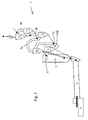
- Figs. 1 to 4 show examples of different kiln plants for manufacturing cement clinker. All the shown kiln plants are of the ILC-type, but the invention may also be used in connection with plants of the SLC-type or other plants which are combinations of such plants.
- All of the plants comprise a cyclone preheater 1 with four cyclones 1a, 1b, 1c and 1d, where 1a is the first cyclone, 1b is the second cyclone, 1c is the third or next-to-last cyclone and 1d is the fourth or last cyclone.
- the cyclones are connected in series and fed with gas/raw meal suspension via gas ducts 2a, 2b, 2c and 2d.
- the plants also comprise a calciner 3 which comprises at least one inlet opening 9 for introducing preheated raw meal from the last cyclone 1d via its material outlet 6, and being connected to a separating cyclone 4, a rotary kiln 5 and a clinker cooler 7.
- the gas duct 2d which connects the separating cyclone to the last cyclone, comprises at least one inlet opening 11 for introducing preheated raw meal from the next-to-last cyclone.
- the inlet opening 11 for introducing preheated raw meal from the next-to-last cyclone 1c into the gas duct 2d which connects the separating cyclone 4 to the last cyclone 1d in a vertical plane is located under at least one inlet opening 9 for introducing preheated raw meal from the last cyclone 1d in the calciner 3.
- the kiln plants shown in Figs. 1 and 2 both comprise a calciner 3 which is designed with a so-called swan's neck which in practice means that the calciner comprises a first upward-directed section 3a, which via a 180° bend 3c is connected to a second downward-directed section 3b which in turn is connected to the separating cyclone 4.
- the cyclone 1d is made up of a conventional cyclone in which the gas/raw meal suspension is introduced tangentially into the upper end of the cyclone and in which the separated raw meal is discharged through the material outlet 6, while the discharge duct 2c for carrying the gas to the cyclone 1c is located at the top of the cyclone 1d.
- the duct 2c comprises a downward-directed section 15 thereby allowing the cyclone 1 c in a vertical plane to be located at a lower level, making it possible to reduce the installation height.
- the cyclone 1d is made up of a cyclone which corresponds to that shown in Fig. 1, except for the fact that the discharge duct 2c for conveying the gas to the cyclone 1c extends through the bottom.
- This embodiment also makes it possible for the cyclone 1c at a vertical plane to be located at a lower level.
- the kiln plant shown in Fig. 3 corresponds to the plant shown in Fig. 1 except for the fact that the calciner 3 is not designed with a swan's neck and that the separating cyclone 4 is designed with a gas discharge duct 2d which extends through the bottom hereof.
- the kiln plant shown in Fig. 4 comprises a calciner 3 in which exit gases from the kiln 5 and fuel are introduced into the upper end 21 of the calciner 3 and led down through the calciner 3 as a suspension.
- Preheated air from the clinker cooler 7 and preheated raw meal from the last cyclone 1d of the preheater 3 is introduced into the calciner 3 at a location further down on the calciner 3, thereby causing the preheated air to be led down through the calciner 3, with the air being gradually mixed with the exit gas/fuel suspension, and with force of gravity causing the raw meal to be led down through the calciner 3 along its wall.
- the raw meal is again suspended in the exit gases whereafter the formed exit gas/raw meal suspension is extracted from the lower end 23 of the calciner 3 and directed to the separating cyclone 4.
- the exit gases are passed upward to the cyclone 1d, which, in similar manner as the embodiment shown in Fig. 1, is made up of a conventional cyclone in which the exit gas/raw meal suspension is introduced tangentially into the upper end of the cyclone, and in which the separated raw meal is discharged through the material outlet 6, while the discharge duct 2c for carrying the gas to the cyclone 1c is located at the top of the cyclone 1d.
- the duct 2c comprises a downward-directed duct section 15 allowing the cyclone 1c in a vertical plane to be located at a low level relative to the upper end of the calciner so that the installation height can be reduced.
Landscapes
- Engineering & Computer Science (AREA)
- Chemical & Material Sciences (AREA)
- Ceramic Engineering (AREA)
- Structural Engineering (AREA)
- Thermal Sciences (AREA)
- Materials Engineering (AREA)
- Physics & Mathematics (AREA)
- Organic Chemistry (AREA)
- Mechanical Engineering (AREA)
- General Engineering & Computer Science (AREA)
- Furnace Details (AREA)
- Curing Cements, Concrete, And Artificial Stone (AREA)
- Cultivation Of Seaweed (AREA)
- Nitrogen And Oxygen Or Sulfur-Condensed Heterocyclic Ring Systems (AREA)
- Waste-Gas Treatment And Other Accessory Devices For Furnaces (AREA)
Abstract
Description
- The present invention relates to a plant for manufacturing cement clinker comprising a preheater which comprises at least one last cyclone and at least one next-to-last cyclone which is connected in series via a gas duct to and fed with gas from the last cyclone, a calciner which comprises at least one inlet opening for introducing preheated raw meal from the last cyclone, and which is connected to a subsequent separating cyclone, a gas duct which connects the separating cyclone to the last cyclone, and which comprises at least one inlet opening for introducing preheated raw meal from the next-to-last cyclone.
- Plants of the aforementioned kind for manufacturing cement are known for example from DE 19649922 and DE 19524649. In these known plants, raw meal is introduced from a mill plant, typically into the gas inlet duct of the first cyclone of the cyclone preheater and the raw meal is preheated as it is led through the cyclones of the preheater in counterflow to a hot gas flow, typically hot exit gases from the subsequent calciner and/or a subsequent kiln. The preheated raw meal is extracted from the last cyclone of the preheater and introduced into the calciner for calcination therein. The calciners described in the above-mentioned patent specifications comprise a first upward-directed section and a subsequent downward-directed section which is connected to the separating cyclone of the calciner. According to the known plants, the preheated raw meal from the last cyclone of the preheater is introduced into the lower end of the upward-directed section of the calciner and, therefore, the last cyclone of the preheater is located next to the calciner due to the overall installation height of the preheater. In instances where it is desirable to introduce preheated raw meal at a higher intake point of the calciner, such raw meal must therefore be extracted from the next-to-last cyclone of the preheater, which is disadvantageous since, because of the lower temperature in the latter, this may result in poor heat economy and also an excessive reduction of the temperature in the calciner.
- It is the objective of the present invention to provide a plant by means of which sufficiently preheated raw meal from the last cyclone of the preheater can be introduced into the upper end of the calciner without causing the installation height of the preheater to be increased.
- This is achived by a plant of the kind mentioned in the introduction and being characterized in that the inlet opening for introducing preheated raw meal from the next-to-last cyclone into the gas duct which connects the separating cyclone to the last cyclone in a vertical plane is located under at least one inlet opening for introducing preheated raw meal from the last cyclone into the calciner.
- Hence, without affecting the installation height of the preheater, it will be possible to locate the last cyclone of the preheater at an arbitrary height relative to the calciner, and preheated raw meal from the last cyclone can therefore be introduced at any point into the calciner without any use of lifting equipment.
- It is preferred that the material outlet from the last cyclone of the preheater in a vertical plane is located above the upper end of the calciner.
- In order to limit the installation height of the preheater, it is preferred that the gas duct which connects the last and next-to-last cyclone of the preheater comprises at least one downward-directed duct section.
- The invention will now be described in further details with reference to drawing where
- Fig. 1 shows a first embodiment of a plant according to the invention,
- Fig. 2 shows a second embodiment of a plant according to the invention,
- Fig. 3 shows a third embodiment of a plant according to the invention, and
- Fig. 4 shows a fourth embodiment of a plant according to the invention.
- Figs. 1 to 4 show examples of different kiln plants for manufacturing cement clinker. All the shown kiln plants are of the ILC-type, but the invention may also be used in connection with plants of the SLC-type or other plants which are combinations of such plants.
- All of the plants comprise a
cyclone preheater 1 with fourcyclones gas ducts - The plants also comprise a
calciner 3 which comprises at least one inlet opening 9 for introducing preheated raw meal from thelast cyclone 1d via itsmaterial outlet 6, and being connected to a separatingcyclone 4, arotary kiln 5 and aclinker cooler 7. Thegas duct 2d which connects the separating cyclone to the last cyclone, comprises at least one inlet opening 11 for introducing preheated raw meal from the next-to-last cyclone. - According to the invention it is a common feature of all the shown plants that the inlet opening 11 for introducing preheated raw meal from the next-to-
last cyclone 1c into thegas duct 2d which connects the separatingcyclone 4 to thelast cyclone 1d in a vertical plane is located under at least one inlet opening 9 for introducing preheated raw meal from thelast cyclone 1d in thecalciner 3. - The kiln plants shown in Figs. 1 and 2 both comprise a
calciner 3 which is designed with a so-called swan's neck which in practice means that the calciner comprises a first upward-directedsection 3a, which via a 180°bend 3c is connected to a second downward-directedsection 3b which in turn is connected to the separatingcyclone 4. - In the kiln plant shown in Fig. 1 the
cyclone 1d is made up of a conventional cyclone in which the gas/raw meal suspension is introduced tangentially into the upper end of the cyclone and in which the separated raw meal is discharged through thematerial outlet 6, while thedischarge duct 2c for carrying the gas to thecyclone 1c is located at the top of thecyclone 1d. In the shown embodiment theduct 2c comprises a downward-directedsection 15 thereby allowing thecyclone 1 c in a vertical plane to be located at a lower level, making it possible to reduce the installation height. - In the kiln plant shown in Fig. 2, the
cyclone 1d is made up of a cyclone which corresponds to that shown in Fig. 1, except for the fact that thedischarge duct 2c for conveying the gas to thecyclone 1c extends through the bottom. This embodiment also makes it possible for thecyclone 1c at a vertical plane to be located at a lower level. - The kiln plant shown in Fig. 3 corresponds to the plant shown in Fig. 1 except for the fact that the
calciner 3 is not designed with a swan's neck and that the separatingcyclone 4 is designed with agas discharge duct 2d which extends through the bottom hereof. - The kiln plant shown in Fig. 4 comprises a
calciner 3 in which exit gases from thekiln 5 and fuel are introduced into theupper end 21 of thecalciner 3 and led down through thecalciner 3 as a suspension. Preheated air from theclinker cooler 7 and preheated raw meal from thelast cyclone 1d of thepreheater 3 is introduced into thecalciner 3 at a location further down on thecalciner 3, thereby causing the preheated air to be led down through thecalciner 3, with the air being gradually mixed with the exit gas/fuel suspension, and with force of gravity causing the raw meal to be led down through thecalciner 3 along its wall. In thelower end 23 of the calciner the raw meal is again suspended in the exit gases whereafter the formed exit gas/raw meal suspension is extracted from thelower end 23 of thecalciner 3 and directed to the separatingcyclone 4. From the separatingcyclone 4 the exit gases are passed upward to thecyclone 1d, which, in similar manner as the embodiment shown in Fig. 1, is made up of a conventional cyclone in which the exit gas/raw meal suspension is introduced tangentially into the upper end of the cyclone, and in which the separated raw meal is discharged through thematerial outlet 6, while thedischarge duct 2c for carrying the gas to thecyclone 1c is located at the top of thecyclone 1d. Theduct 2c comprises a downward-directedduct section 15 allowing thecyclone 1c in a vertical plane to be located at a low level relative to the upper end of the calciner so that the installation height can be reduced. - The present invention is not limited to the shown embodiments which are illustrative only, thus allowing for many different embodiments and combinations of the shown embodiments which are within the scope the present invention.
Claims (3)
- Plant for manufacturing cement clinker comprising a preheater (1) which comprises at least one last cyclone (1d) and at least one next-to-last cyclone (1c) which is connected in series via a gas duct (2c) to and fed with gas from the last cyclone (1d), a calciner (3) which comprises at least one inlet opening (9) for introducing preheated raw meal from the last cyclone (1d), and which is connected to a subsequent separating cyclone (4), a gas duct (2d) which connects the separating cyclone (4) to the last cyclone (1d), and which comprises at least one inlet opening (11) for introducing preheated raw meal from the next-to-last cyclone (1c), characterized in that the inlet opening (11) for introducing preheated raw meal from the next-to-last cyclone (1c) into the gas duct (2d) which connects the separating cyclone (4) to the last cyclone (1d) in a vertical plane is located under at least one inlet opening (9) for introducing preheated raw meal from the last cyclone (1d) into the calciner.
- Plant according to claim 1, characterized in that the material outlet (6) from the last cyclone (1d) of the preheater in a vertical plane is located above the upper end of the calciner (21).
- Plant according to claim 1, characterized in that the gas duct (2c) which connects the last (1 d) and next-to-last cyclone (1 c) of the preheater comprises at least one downward-directed duct section (15).
Applications Claiming Priority (3)
| Application Number | Priority Date | Filing Date | Title |
|---|---|---|---|
| DK200001390A DK174192B1 (en) | 2000-09-20 | 2000-09-20 | Cement clinker manufacturing plant. |
| DK200001390 | 2000-09-20 | ||
| PCT/IB2001/001291 WO2002025196A1 (en) | 2000-09-20 | 2001-07-19 | Plant for manufacturing cement clinker |
Publications (2)
| Publication Number | Publication Date |
|---|---|
| EP1322899A1 EP1322899A1 (en) | 2003-07-02 |
| EP1322899B1 true EP1322899B1 (en) | 2006-12-13 |
Family
ID=8159725
Family Applications (1)
| Application Number | Title | Priority Date | Filing Date |
|---|---|---|---|
| EP01947747A Revoked EP1322899B1 (en) | 2000-09-20 | 2001-07-19 | Plant for manufacturing cement clinker |
Country Status (19)
| Country | Link |
|---|---|
| US (1) | US6902393B2 (en) |
| EP (1) | EP1322899B1 (en) |
| JP (1) | JP2004509057A (en) |
| KR (1) | KR100728426B1 (en) |
| CN (1) | CN1330921C (en) |
| AT (1) | ATE348304T1 (en) |
| AU (2) | AU6938701A (en) |
| BR (1) | BR0113892A (en) |
| CA (1) | CA2422102A1 (en) |
| DE (1) | DE60125205T2 (en) |
| DK (1) | DK174192B1 (en) |
| ES (1) | ES2275695T3 (en) |
| MX (1) | MXPA03002366A (en) |
| PL (1) | PL195612B1 (en) |
| PT (1) | PT1322899E (en) |
| RU (1) | RU2268447C2 (en) |
| TW (1) | TW555727B (en) |
| WO (1) | WO2002025196A1 (en) |
| ZA (1) | ZA200302041B (en) |
Cited By (1)
| Publication number | Priority date | Publication date | Assignee | Title |
|---|---|---|---|---|
| WO2014048435A1 (en) * | 2012-09-27 | 2014-04-03 | Flsmidth A/S | Plant for manufacturing cement clinker |
Families Citing this family (3)
| Publication number | Priority date | Publication date | Assignee | Title |
|---|---|---|---|---|
| TWI359124B (en) * | 2003-10-29 | 2012-03-01 | Smidth As F L | Method and plant for preheating particulate or pul |
| DE502006006934D1 (en) * | 2005-01-25 | 2010-06-24 | Klingbeil Lothar | MULTI-STAGE HEAT EXCHANGER AND CYCLONE SEPARATOR FOR USE IN SUCH A HEAT EXCHANGER |
| DK176268B1 (en) * | 2006-05-10 | 2007-05-21 | Smidth As F L | Method and installation are for production of cement clinker |
Family Cites Families (15)
| Publication number | Priority date | Publication date | Assignee | Title |
|---|---|---|---|---|
| US474879A (en) * | 1892-05-17 | Ice-pick | ||
| JPS5255497Y2 (en) * | 1972-03-07 | 1977-12-15 | ||
| JPS6053267B2 (en) * | 1980-12-15 | 1985-11-25 | 秩父セメント株式会社 | Powder raw material calcination equipment |
| FR2505813A1 (en) * | 1981-05-15 | 1982-11-19 | Fives Cail Babcock | IMPROVEMENTS IN PROCESSES AND INSTALLATIONS FOR THE PRODUCTION OF DRY CEMENT CLINKER |
| DE3341695A1 (en) * | 1983-11-18 | 1985-05-30 | Klöckner-Humboldt-Deutz AG, 5000 Köln | METHOD AND PLANT FOR BURNING FINE-GRAINED GOODS, IN PARTICULAR FOR PRODUCING CEMENT CLINKERS FROM CEMENT FLOUR |
| MX164848B (en) * | 1985-06-03 | 1992-09-25 | Smidth & Co As F L | IMPROVED METHOD FOR PRODUCING SLAG |
| DE3538707A1 (en) * | 1985-10-31 | 1987-05-07 | Kloeckner Humboldt Deutz Ag | METHOD AND DEVICE FOR THE THERMAL TREATMENT OF MOLDED RAW MATERIALS |
| US5365866A (en) * | 1992-12-08 | 1994-11-22 | Southdown, Inc. | Method and apparatus for treating exhaust gases from preheater and preheater/precalciner kilns burning hazardous waste fuels |
| DE4435871A1 (en) * | 1994-10-07 | 1996-04-11 | Heidelberger Zement Ag | Heat exchanger for kiln gas in a cement plant |
| DE19524649A1 (en) * | 1995-07-06 | 1997-01-09 | Kloeckner Humboldt Deutz Ag | Preheating and firing plant esp. for clinker mfr. |
| DE19649922A1 (en) * | 1996-12-02 | 1998-06-04 | Krupp Polysius Ag | Method and device for the heat treatment of fine-grained material |
| CN1124998C (en) * | 1996-02-14 | 2003-10-22 | 弗·尔·斯米德恩公司 | Method for reducing NOx emission from a kiln plant |
| GB9608341D0 (en) * | 1996-04-23 | 1996-06-26 | Blue Circle Ind Plc | Disposal of waste tyres |
| DK0882687T3 (en) * | 1997-06-02 | 2000-07-31 | Doumet Joseph E Dipl Ing | Method and apparatus for making cement articles |
| DE19854582B4 (en) * | 1998-11-25 | 2007-11-22 | Khd Humboldt Wedag Gmbh | Process for the thermal treatment of cement raw meal |
-
2000
- 2000-09-20 DK DK200001390A patent/DK174192B1/en not_active IP Right Cessation
-
2001
- 2001-05-30 TW TW090113067A patent/TW555727B/en active
- 2001-07-19 AU AU6938701A patent/AU6938701A/en active Pending
- 2001-07-19 PT PT01947747T patent/PT1322899E/en unknown
- 2001-07-19 AT AT01947747T patent/ATE348304T1/en not_active IP Right Cessation
- 2001-07-19 EP EP01947747A patent/EP1322899B1/en not_active Revoked
- 2001-07-19 JP JP2002528756A patent/JP2004509057A/en active Pending
- 2001-07-19 AU AU2001269387A patent/AU2001269387B2/en not_active Ceased
- 2001-07-19 ES ES01947747T patent/ES2275695T3/en not_active Expired - Lifetime
- 2001-07-19 CN CNB018147828A patent/CN1330921C/en not_active Expired - Fee Related
- 2001-07-19 KR KR1020037004000A patent/KR100728426B1/en not_active Expired - Fee Related
- 2001-07-19 WO PCT/IB2001/001291 patent/WO2002025196A1/en not_active Ceased
- 2001-07-19 MX MXPA03002366A patent/MXPA03002366A/en active IP Right Grant
- 2001-07-19 BR BR0113892-8A patent/BR0113892A/en active Search and Examination
- 2001-07-19 DE DE60125205T patent/DE60125205T2/en not_active Revoked
- 2001-07-19 CA CA002422102A patent/CA2422102A1/en not_active Abandoned
- 2001-07-19 US US10/380,702 patent/US6902393B2/en not_active Expired - Fee Related
- 2001-07-19 ZA ZA200302041A patent/ZA200302041B/en unknown
- 2001-07-19 RU RU2003107670/03A patent/RU2268447C2/en not_active IP Right Cessation
- 2001-07-19 PL PL01360354A patent/PL195612B1/en not_active IP Right Cessation
Cited By (1)
| Publication number | Priority date | Publication date | Assignee | Title |
|---|---|---|---|---|
| WO2014048435A1 (en) * | 2012-09-27 | 2014-04-03 | Flsmidth A/S | Plant for manufacturing cement clinker |
Also Published As
| Publication number | Publication date |
|---|---|
| WO2002025196A1 (en) | 2002-03-28 |
| CA2422102A1 (en) | 2002-03-28 |
| DK174192B1 (en) | 2002-09-09 |
| DK200001390A (en) | 2002-03-21 |
| AU6938701A (en) | 2002-04-02 |
| ATE348304T1 (en) | 2007-01-15 |
| US6902393B2 (en) | 2005-06-07 |
| KR100728426B1 (en) | 2007-06-15 |
| PL360354A1 (en) | 2004-09-06 |
| DE60125205D1 (en) | 2007-01-25 |
| ES2275695T3 (en) | 2007-06-16 |
| US20040053183A1 (en) | 2004-03-18 |
| BR0113892A (en) | 2003-07-22 |
| PT1322899E (en) | 2007-03-30 |
| TW555727B (en) | 2003-10-01 |
| CN1330921C (en) | 2007-08-08 |
| JP2004509057A (en) | 2004-03-25 |
| EP1322899A1 (en) | 2003-07-02 |
| ZA200302041B (en) | 2004-03-15 |
| KR20030043961A (en) | 2003-06-02 |
| PL195612B1 (en) | 2007-10-31 |
| CN1449483A (en) | 2003-10-15 |
| DE60125205T2 (en) | 2007-09-20 |
| AU2001269387B2 (en) | 2005-10-27 |
| MXPA03002366A (en) | 2003-06-30 |
| RU2268447C2 (en) | 2006-01-20 |
Similar Documents
| Publication | Publication Date | Title |
|---|---|---|
| CN1190386C (en) | Method and apparatus for producing cement clinker | |
| US4039277A (en) | Apparatus for calcining powder materials | |
| US4260369A (en) | Method of converting a rotary kiln cement making plant to a calcining furnace cement making plant | |
| EP0103423B2 (en) | Apparatus for burning pulverulent raw material | |
| US6902393B2 (en) | Plant for manufacturing cement clinker | |
| US4318692A (en) | Helical duct gas/meal separator | |
| AU2001269387A1 (en) | Plant for manufacturing cement clinker | |
| US4326845A (en) | Suspension preheater for cement calcining plant | |
| CA2287368A1 (en) | Removal of sulfur oxides from preheater off gases | |
| EP0048537A1 (en) | Kiln plant for burning granular or pulverulent material | |
| US6485295B1 (en) | Equipment for calcination | |
| US4901448A (en) | Suspension preheater | |
| US5566467A (en) | Cyclone heat exchanger | |
| DK1302452T3 (en) | Multi-string plant for the production of cement clinker from raw flour | |
| JPS5911335B2 (en) | How to modify the suspension preheater | |
| CN209745013U (en) | A cement production preheater | |
| SU1406438A1 (en) | Off-furnace cyclone heat exchanger | |
| JPH0527469Y2 (en) | ||
| WO2014048435A1 (en) | Plant for manufacturing cement clinker | |
| JPH0424630B2 (en) | ||
| JPH0341209B2 (en) | ||
| JPS6365297A (en) | Powdered raw material preheater |
Legal Events
| Date | Code | Title | Description |
|---|---|---|---|
| PUAI | Public reference made under article 153(3) epc to a published international application that has entered the european phase |
Free format text: ORIGINAL CODE: 0009012 |
|
| 17P | Request for examination filed |
Effective date: 20030307 |
|
| AK | Designated contracting states |
Designated state(s): AT BE CH CY DE DK ES FI FR GB GR IE IT LI LU MC NL PT SE TR |
|
| AX | Request for extension of the european patent |
Extension state: AL LT LV MK RO SI |
|
| GRAP | Despatch of communication of intention to grant a patent |
Free format text: ORIGINAL CODE: EPIDOSNIGR1 |
|
| GRAS | Grant fee paid |
Free format text: ORIGINAL CODE: EPIDOSNIGR3 |
|
| GRAA | (expected) grant |
Free format text: ORIGINAL CODE: 0009210 |
|
| AK | Designated contracting states |
Kind code of ref document: B1 Designated state(s): AT BE CH CY DE DK ES FI FR GB GR IE IT LI LU MC NL PT SE TR |
|
| PG25 | Lapsed in a contracting state [announced via postgrant information from national office to epo] |
Ref country code: NL Free format text: LAPSE BECAUSE OF FAILURE TO SUBMIT A TRANSLATION OF THE DESCRIPTION OR TO PAY THE FEE WITHIN THE PRESCRIBED TIME-LIMIT Effective date: 20061213 Ref country code: AT Free format text: LAPSE BECAUSE OF FAILURE TO SUBMIT A TRANSLATION OF THE DESCRIPTION OR TO PAY THE FEE WITHIN THE PRESCRIBED TIME-LIMIT Effective date: 20061213 Ref country code: CH Free format text: LAPSE BECAUSE OF FAILURE TO SUBMIT A TRANSLATION OF THE DESCRIPTION OR TO PAY THE FEE WITHIN THE PRESCRIBED TIME-LIMIT Effective date: 20061213 Ref country code: LI Free format text: LAPSE BECAUSE OF FAILURE TO SUBMIT A TRANSLATION OF THE DESCRIPTION OR TO PAY THE FEE WITHIN THE PRESCRIBED TIME-LIMIT Effective date: 20061213 Ref country code: FI Free format text: LAPSE BECAUSE OF FAILURE TO SUBMIT A TRANSLATION OF THE DESCRIPTION OR TO PAY THE FEE WITHIN THE PRESCRIBED TIME-LIMIT Effective date: 20061213 Ref country code: BE Free format text: LAPSE BECAUSE OF FAILURE TO SUBMIT A TRANSLATION OF THE DESCRIPTION OR TO PAY THE FEE WITHIN THE PRESCRIBED TIME-LIMIT Effective date: 20061213 Ref country code: DK Free format text: LAPSE BECAUSE OF FAILURE TO SUBMIT A TRANSLATION OF THE DESCRIPTION OR TO PAY THE FEE WITHIN THE PRESCRIBED TIME-LIMIT Effective date: 20061213 |
|
| REG | Reference to a national code |
Ref country code: GB Ref legal event code: FG4D |
|
| REG | Reference to a national code |
Ref country code: CH Ref legal event code: EP |
|
| REG | Reference to a national code |
Ref country code: IE Ref legal event code: FG4D |
|
| REF | Corresponds to: |
Ref document number: 60125205 Country of ref document: DE Date of ref document: 20070125 Kind code of ref document: P |
|
| PG25 | Lapsed in a contracting state [announced via postgrant information from national office to epo] |
Ref country code: SE Free format text: LAPSE BECAUSE OF FAILURE TO SUBMIT A TRANSLATION OF THE DESCRIPTION OR TO PAY THE FEE WITHIN THE PRESCRIBED TIME-LIMIT Effective date: 20070313 |
|
| REG | Reference to a national code |
Ref country code: GR Ref legal event code: EP Ref document number: 20070400391 Country of ref document: GR |
|
| REG | Reference to a national code |
Ref country code: PT Ref legal event code: SC4A Free format text: AVAILABILITY OF NATIONAL TRANSLATION Effective date: 20070219 |
|
| ET | Fr: translation filed | ||
| NLV1 | Nl: lapsed or annulled due to failure to fulfill the requirements of art. 29p and 29m of the patents act | ||
| REG | Reference to a national code |
Ref country code: ES Ref legal event code: FG2A Ref document number: 2275695 Country of ref document: ES Kind code of ref document: T3 |
|
| REG | Reference to a national code |
Ref country code: CH Ref legal event code: PL |
|
| PLBI | Opposition filed |
Free format text: ORIGINAL CODE: 0009260 |
|
| PLAX | Notice of opposition and request to file observation + time limit sent |
Free format text: ORIGINAL CODE: EPIDOSNOBS2 |
|
| 26 | Opposition filed |
Opponent name: POLYSIUS AG Effective date: 20070910 |
|
| PLBB | Reply of patent proprietor to notice(s) of opposition received |
Free format text: ORIGINAL CODE: EPIDOSNOBS3 |
|
| PG25 | Lapsed in a contracting state [announced via postgrant information from national office to epo] |
Ref country code: MC Free format text: LAPSE BECAUSE OF NON-PAYMENT OF DUE FEES Effective date: 20070731 |
|
| PGFP | Annual fee paid to national office [announced via postgrant information from national office to epo] |
Ref country code: PT Payment date: 20080627 Year of fee payment: 8 |
|
| PG25 | Lapsed in a contracting state [announced via postgrant information from national office to epo] |
Ref country code: IE Free format text: LAPSE BECAUSE OF NON-PAYMENT OF DUE FEES Effective date: 20070719 |
|
| PGFP | Annual fee paid to national office [announced via postgrant information from national office to epo] |
Ref country code: DE Payment date: 20080724 Year of fee payment: 8 Ref country code: ES Payment date: 20080821 Year of fee payment: 8 |
|
| PGFP | Annual fee paid to national office [announced via postgrant information from national office to epo] |
Ref country code: FR Payment date: 20080718 Year of fee payment: 8 Ref country code: IT Payment date: 20080730 Year of fee payment: 8 |
|
| PGFP | Annual fee paid to national office [announced via postgrant information from national office to epo] |
Ref country code: GB Payment date: 20080723 Year of fee payment: 8 |
|
| RDAF | Communication despatched that patent is revoked |
Free format text: ORIGINAL CODE: EPIDOSNREV1 |
|
| PGFP | Annual fee paid to national office [announced via postgrant information from national office to epo] |
Ref country code: GR Payment date: 20080619 Year of fee payment: 8 |
|
| RDAG | Patent revoked |
Free format text: ORIGINAL CODE: 0009271 |
|
| STAA | Information on the status of an ep patent application or granted ep patent |
Free format text: STATUS: PATENT REVOKED |
|
| PG25 | Lapsed in a contracting state [announced via postgrant information from national office to epo] |
Ref country code: LU Free format text: LAPSE BECAUSE OF NON-PAYMENT OF DUE FEES Effective date: 20070719 Ref country code: CY Free format text: LAPSE BECAUSE OF FAILURE TO SUBMIT A TRANSLATION OF THE DESCRIPTION OR TO PAY THE FEE WITHIN THE PRESCRIBED TIME-LIMIT Effective date: 20061213 |
|
| 27W | Patent revoked |
Effective date: 20090522 |
|
| GBPR | Gb: patent revoked under art. 102 of the ep convention designating the uk as contracting state |
Effective date: 20090522 |
|
| PG25 | Lapsed in a contracting state [announced via postgrant information from national office to epo] |
Ref country code: TR Free format text: LAPSE BECAUSE OF FAILURE TO SUBMIT A TRANSLATION OF THE DESCRIPTION OR TO PAY THE FEE WITHIN THE PRESCRIBED TIME-LIMIT Effective date: 20061213 |
|
| REG | Reference to a national code |
Ref country code: PT Ref legal event code: MM4A Free format text: LAPSE DUE TO NON-PAYMENT OF FEES Effective date: 20100119 |