EP1322564B1 - Bonded fibre products - Google Patents
Bonded fibre products Download PDFInfo
- Publication number
- EP1322564B1 EP1322564B1 EP01980229A EP01980229A EP1322564B1 EP 1322564 B1 EP1322564 B1 EP 1322564B1 EP 01980229 A EP01980229 A EP 01980229A EP 01980229 A EP01980229 A EP 01980229A EP 1322564 B1 EP1322564 B1 EP 1322564B1
- Authority
- EP
- European Patent Office
- Prior art keywords
- batt
- metres
- length
- width
- continuous
- Prior art date
- Legal status (The legal status is an assumption and is not a legal conclusion. Google has not performed a legal analysis and makes no representation as to the accuracy of the status listed.)
- Expired - Lifetime
Links
- 239000000835 fiber Substances 0.000 title claims description 5
- 238000005520 cutting process Methods 0.000 claims abstract description 10
- 238000000034 method Methods 0.000 claims description 9
- 239000011230 binding agent Substances 0.000 claims description 7
- 229910052500 inorganic mineral Inorganic materials 0.000 claims description 5
- 239000011707 mineral Substances 0.000 claims description 5
- 238000004806 packaging method and process Methods 0.000 claims description 5
- 239000007767 bonding agent Substances 0.000 claims description 2
- 238000011067 equilibration Methods 0.000 claims description 2
- 239000000047 product Substances 0.000 description 8
- 238000004519 manufacturing process Methods 0.000 description 5
- 230000006835 compression Effects 0.000 description 3
- 238000007906 compression Methods 0.000 description 3
- 238000010276 construction Methods 0.000 description 3
- 238000005096 rolling process Methods 0.000 description 3
- 239000002985 plastic film Substances 0.000 description 2
- 229920006255 plastic film Polymers 0.000 description 2
- 238000009987 spinning Methods 0.000 description 2
- 238000007796 conventional method Methods 0.000 description 1
- 239000012467 final product Substances 0.000 description 1
- 239000000463 material Substances 0.000 description 1
- 238000005259 measurement Methods 0.000 description 1
- 239000004033 plastic Substances 0.000 description 1
- 238000000926 separation method Methods 0.000 description 1
Images

Classifications
-
- D—TEXTILES; PAPER
- D04—BRAIDING; LACE-MAKING; KNITTING; TRIMMINGS; NON-WOVEN FABRICS
- D04H—MAKING TEXTILE FABRICS, e.g. FROM FIBRES OR FILAMENTARY MATERIAL; FABRICS MADE BY SUCH PROCESSES OR APPARATUS, e.g. FELTS, NON-WOVEN FABRICS; COTTON-WOOL; WADDING ; NON-WOVEN FABRICS FROM STAPLE FIBRES, FILAMENTS OR YARNS, BONDED WITH AT LEAST ONE WEB-LIKE MATERIAL DURING THEIR CONSOLIDATION
- D04H1/00—Non-woven fabrics formed wholly or mainly of staple fibres or like relatively short fibres
- D04H1/70—Non-woven fabrics formed wholly or mainly of staple fibres or like relatively short fibres characterised by the method of forming fleeces or layers, e.g. reorientation of fibres
- D04H1/74—Non-woven fabrics formed wholly or mainly of staple fibres or like relatively short fibres characterised by the method of forming fleeces or layers, e.g. reorientation of fibres the fibres being orientated, e.g. in parallel (anisotropic fleeces)
-
- D—TEXTILES; PAPER
- D04—BRAIDING; LACE-MAKING; KNITTING; TRIMMINGS; NON-WOVEN FABRICS
- D04H—MAKING TEXTILE FABRICS, e.g. FROM FIBRES OR FILAMENTARY MATERIAL; FABRICS MADE BY SUCH PROCESSES OR APPARATUS, e.g. FELTS, NON-WOVEN FABRICS; COTTON-WOOL; WADDING ; NON-WOVEN FABRICS FROM STAPLE FIBRES, FILAMENTS OR YARNS, BONDED WITH AT LEAST ONE WEB-LIKE MATERIAL DURING THEIR CONSOLIDATION
- D04H1/00—Non-woven fabrics formed wholly or mainly of staple fibres or like relatively short fibres
- D04H1/40—Non-woven fabrics formed wholly or mainly of staple fibres or like relatively short fibres from fleeces or layers composed of fibres without existing or potential cohesive properties
- D04H1/42—Non-woven fabrics formed wholly or mainly of staple fibres or like relatively short fibres from fleeces or layers composed of fibres without existing or potential cohesive properties characterised by the use of certain kinds of fibres insofar as this use has no preponderant influence on the consolidation of the fleece
- D04H1/4209—Inorganic fibres
- D04H1/4218—Glass fibres
- D04H1/4226—Glass fibres characterised by the apparatus for manufacturing the glass fleece
-
- D—TEXTILES; PAPER
- D04—BRAIDING; LACE-MAKING; KNITTING; TRIMMINGS; NON-WOVEN FABRICS
- D04H—MAKING TEXTILE FABRICS, e.g. FROM FIBRES OR FILAMENTARY MATERIAL; FABRICS MADE BY SUCH PROCESSES OR APPARATUS, e.g. FELTS, NON-WOVEN FABRICS; COTTON-WOOL; WADDING ; NON-WOVEN FABRICS FROM STAPLE FIBRES, FILAMENTS OR YARNS, BONDED WITH AT LEAST ONE WEB-LIKE MATERIAL DURING THEIR CONSOLIDATION
- D04H1/00—Non-woven fabrics formed wholly or mainly of staple fibres or like relatively short fibres
- D04H1/40—Non-woven fabrics formed wholly or mainly of staple fibres or like relatively short fibres from fleeces or layers composed of fibres without existing or potential cohesive properties
- D04H1/58—Non-woven fabrics formed wholly or mainly of staple fibres or like relatively short fibres from fleeces or layers composed of fibres without existing or potential cohesive properties by applying, incorporating or activating chemical or thermoplastic bonding agents, e.g. adhesives
- D04H1/64—Non-woven fabrics formed wholly or mainly of staple fibres or like relatively short fibres from fleeces or layers composed of fibres without existing or potential cohesive properties by applying, incorporating or activating chemical or thermoplastic bonding agents, e.g. adhesives the bonding agent being applied in wet state, e.g. chemical agents in dispersions or solutions
-
- D—TEXTILES; PAPER
- D04—BRAIDING; LACE-MAKING; KNITTING; TRIMMINGS; NON-WOVEN FABRICS
- D04H—MAKING TEXTILE FABRICS, e.g. FROM FIBRES OR FILAMENTARY MATERIAL; FABRICS MADE BY SUCH PROCESSES OR APPARATUS, e.g. FELTS, NON-WOVEN FABRICS; COTTON-WOOL; WADDING ; NON-WOVEN FABRICS FROM STAPLE FIBRES, FILAMENTS OR YARNS, BONDED WITH AT LEAST ONE WEB-LIKE MATERIAL DURING THEIR CONSOLIDATION
- D04H1/00—Non-woven fabrics formed wholly or mainly of staple fibres or like relatively short fibres
- D04H1/70—Non-woven fabrics formed wholly or mainly of staple fibres or like relatively short fibres characterised by the method of forming fleeces or layers, e.g. reorientation of fibres
- D04H1/72—Non-woven fabrics formed wholly or mainly of staple fibres or like relatively short fibres characterised by the method of forming fleeces or layers, e.g. reorientation of fibres the fibres being randomly arranged
- D04H1/732—Non-woven fabrics formed wholly or mainly of staple fibres or like relatively short fibres characterised by the method of forming fleeces or layers, e.g. reorientation of fibres the fibres being randomly arranged by fluid current, e.g. air-lay
-
- D—TEXTILES; PAPER
- D04—BRAIDING; LACE-MAKING; KNITTING; TRIMMINGS; NON-WOVEN FABRICS
- D04H—MAKING TEXTILE FABRICS, e.g. FROM FIBRES OR FILAMENTARY MATERIAL; FABRICS MADE BY SUCH PROCESSES OR APPARATUS, e.g. FELTS, NON-WOVEN FABRICS; COTTON-WOOL; WADDING ; NON-WOVEN FABRICS FROM STAPLE FIBRES, FILAMENTS OR YARNS, BONDED WITH AT LEAST ONE WEB-LIKE MATERIAL DURING THEIR CONSOLIDATION
- D04H13/00—Other non-woven fabrics
-
- D—TEXTILES; PAPER
- D04—BRAIDING; LACE-MAKING; KNITTING; TRIMMINGS; NON-WOVEN FABRICS
- D04H—MAKING TEXTILE FABRICS, e.g. FROM FIBRES OR FILAMENTARY MATERIAL; FABRICS MADE BY SUCH PROCESSES OR APPARATUS, e.g. FELTS, NON-WOVEN FABRICS; COTTON-WOOL; WADDING ; NON-WOVEN FABRICS FROM STAPLE FIBRES, FILAMENTS OR YARNS, BONDED WITH AT LEAST ONE WEB-LIKE MATERIAL DURING THEIR CONSOLIDATION
- D04H3/00—Non-woven fabrics formed wholly or mainly of yarns or like filamentary material of substantial length
- D04H3/002—Inorganic yarns or filaments
- D04H3/004—Glass yarns or filaments
-
- D—TEXTILES; PAPER
- D04—BRAIDING; LACE-MAKING; KNITTING; TRIMMINGS; NON-WOVEN FABRICS
- D04H—MAKING TEXTILE FABRICS, e.g. FROM FIBRES OR FILAMENTARY MATERIAL; FABRICS MADE BY SUCH PROCESSES OR APPARATUS, e.g. FELTS, NON-WOVEN FABRICS; COTTON-WOOL; WADDING ; NON-WOVEN FABRICS FROM STAPLE FIBRES, FILAMENTS OR YARNS, BONDED WITH AT LEAST ONE WEB-LIKE MATERIAL DURING THEIR CONSOLIDATION
- D04H3/00—Non-woven fabrics formed wholly or mainly of yarns or like filamentary material of substantial length
- D04H3/08—Non-woven fabrics formed wholly or mainly of yarns or like filamentary material of substantial length characterised by the method of strengthening or consolidating
- D04H3/12—Non-woven fabrics formed wholly or mainly of yarns or like filamentary material of substantial length characterised by the method of strengthening or consolidating with filaments or yarns secured together by chemical or thermo-activatable bonding agents, e.g. adhesives, applied or incorporated in liquid or solid form
Definitions
- This invention relates to bonded man-made vitreous fibre (MMVF) batts which may be of relatively low density (such as 5 to 50kg/m 3 ) and in particular to elongated pieces cut from such batts and supplied to the user as a compressed packaged roll.
- MMVF vitreous fibre
- One conventional way of producing such batts involves fiberising mineral melt on a centrifugal spinning apparatus and thereby forming a cloud of fibres entrained in air, including curable binder in the cloud, carrying the cloud forwards from the spinner in a stream of air, collecting the cloud of fibres as a primary web on a substantially continuous moving collector, transporting the web to a cross-lapping position, cross-lapping a plurality of layers of the web while substantially continuously conveying the resultant continuous batt from the cross-lapping position, curing the binder by passing the batt through a curing oven and cutting the continuous batt into elongated pieces before, during or after curing, and compressing and packaging the elongated pieces of batt as rolls.
- the continuous batt can be considered as having upper and lower faces which extend in the X and Y axes or directions with the X direction being the width of the batt as it is collected and the Y direction being the length of the continuous batt as it is collected and carried away from the cross lapping position.
- the quality of the final product tends to deteriorate as the primary web increases in thickness, and so there is an incentive for the primary web to have reduced thickness.
- reducing the thickness of the primary web results in reduced productivity (tons per hour) unless either the web is made wider than usual or the web is made to travel faster than usual.
- the normal maximum width of the primary web is 2 metres, although widths of webs (made by other methods) of up to 2.5 metres are mentioned in DE 3501897 A and up to 4 metres in WO 99/51535 A.
- Increasing the speed of travel of the web has the disadvantage of increasing the frequency of reciprocation of the cross lapping apparatus, and this causes engineering problems. It would be desirable to achieve increased productivity whilst minimising or avoiding these problems and whilst maintaining quality.
- continuous bonded batt may be used in various forms, most continuous batt is converted into elongated pieces of batt usually having a length greater than the width.
- the normal width of the continuous batt in the X direction is up to 2 metres (although a width of up to 2.5 metres is described in DE 3501897 for batts made by different fiberising techniques) with the result that the maximum length of pieces cut from the batt is normally 2 metres if the pieces are cut transversely, along the X direction.
- the cut pieces usually have a shorter dimension in the Y direction and so have a width below 2 metres. Because the maximum length in the X direction is, in normal practice, 2 metres, this curtails the type of products which can be made by cutting in this direction. In particular, transverse cutting along the X direction cannot provide elongated pieces having a length above 2 metres.
- the present invention simultaneously solves all these problems.
- an elongated, bonded man-made vitreous fibre (MMVF) batt which has a length direction X and a width direction Y and which has upper and lower faces which extend in the X and Y direction and wherein the batt is formed of a compressed and cured intermeshed stack of layers each of which is formed of air laid MMVF primary web which includes a bonding agent and wherein, each layer is substantially parallel to the faces when viewed in cross section along the X direction, the layers are regularly displaced relative to each other in zig-zag fashion in the Y direction, and each layer is inclined to the faces when viewed in cross section along the Y direction, characterised in that the layers between the faces extend as continuous layers throughout the X direction, the length in the X direction is at least 3 metres and is greater than the width in the Y direction and the batt is in the form of a compressed and packaged roll whose axis extends in the Y direction.
- MMVF vitreous fibre
- the length of the batt in the X direction is at least 4 metres, for instance as much as 6 or even 8 metres.
- the length in the X direction is usually at least two times longer than the width in the Y direction.
- the products of the invention are made by fiberising mineral melt on a centrifugal fiberising apparatus and thereby forming a cloud of fibres entrained in air, including curable binder in the cloud, carrying the cloud forwards from the spinner in a stream of air, collecting the cloud of fibres as a web on a substantially continuously moving collector, transporting the web to a cross lapping position, cross lapping a plurality of layers of the web while substantially continuously conveying the resultant continuous batt away from the cross lapping position along the Y direction of the batt, curing the binder by passing the batt through a curing oven, and cutting the continuous batt along the X direction (transverse to the Y direction of the continuous batt) into pieces before, during or after curing, and packaging each piece as a compressed roll, and in this process the cross lapped continuous batt and each of the pieces has a length in the X direction of, and the width of the curing oven is, at least 3 metres and the width of each of the pieces in the Y direction is less than the
- the cross lapping is conducted to produce a continuous batt which is wider (in the X direction) than usual, and in particular is at least 3 metres wide and often 4 metres up to 6 metres or even 8 metres wide, and this very wide batt is then cut transversely.
- the length of the curing oven can be reduced.
- increased production can be achieved by a fast primary web speed and a wide batt, without the need to increase the length of the curing oven unacceptably.
- the curing oven merely needs to be made wider, and in many plants this is a significantly preferred option compared to increasing the length of the oven.
- the batt is cut transversely to provide elongated pieces having a dimension in the X direction of at least 3 metres and generally at least 4 metres and with a lesser dimension in the Y direction, for instance up to 1 metre or 2 metres.
- the product of the invention is a compressed and packaged roll which, when unwound, has better tensile strength in the length direction than conventional roll products having a length of at least 3 or 4 metres, since these conventional products have their major length extending in the Y direction.
- the axis of the roll extends along the Y axis, ie. transverse to the length direction of the initial batt.
- each piece may be rolled tight with plastic film trapped between the layers of the roll, at least towards the end of the piece, and then sealed to itself after rolling, thereby trapping the roll in an envelope of plastic film.
- Other conventional methods of packaging the roll in its compressed state can be used.
- the amount of compression of the roll is generally such that the thickness and volume of the roll is 10 to 50% of the norm volume of the batt.
- the extent of compression is typically from about 50% to about 90% based on the volume of the batt.
- the thickness is generally at least 50mm and usually at least 80 to 100mm. It is frequently up to 180 or 220mm and can be up to 250mm.
- the thickness of the batt before being compressed and rolled is likewise usually within the range 50mm to 250mm. Usually the thickness before rolling and compression is 5 to 20%, often around 10%, more than the desired thickness after unrolling and equilibration.
- thickness is determined by laying the product on a hard flat surface, laying a 200mm x 200mm pressure plate on the surface so as to apply a pressure of 50Pa and measuring the separation between the supporting surface and the plate.
- the measured thickness is the average of values taken at a number of points .
- the number of points is 5 when the roll is 2 metres long, 7 when 3 metres long and 9 when 4 metres long, with the points being distributed uniformly over the width of the roll but excluding the outer 150mm of the width.
- the products of the invention usually have a nominal density of 5 to 50kg/m 3 , and generally at least 15 or 20kg/m 3 up to 40 or 45kg/m 3 .
- the product after unrolling and equilibrating has a density in these ranges.
- the density is derived by calculation from the thickness, measured as above, and measurements of the surface area of the unrolled material and its mass.
- MMVF rolls of provide a tensile strength of 3 to 4kN/m 2 in the length direction (along the Y axis) (indexed to 30kg/m 3 density and ignition loss 1.4%) but in the invention typical values for slabs can be from 6 to 8 kN/m 2 in the length direction because the length direction is along the X direction during initial manufacture of the batt which is cut to provide the elongated pieces.
- the primary web is as described in our application GB 0019999.2 filed 14 August 2000 and in our PCT application WO 01/23312 A filed even date herewith, wherein the primary web also has a width of, generally, at least 3 metres and preferably 4 to 8 metres.
- the fibres are preferably made using one more centrifugal cascade spinners each comprising a first rotor and one or more subsequent rotors which rotate about the substantially horizontal axis and thereby form the cloud of fibres entrained in air.
- Suitable apparatus and techniques for forming the fibres are described in, for instance, WO 92/06047 A, WO 92/12939 A, WO 92/12.940 A, -WO 96/38391 A and WO 99/51535 A.
- three cascade spinners 1, 2 and 3 each having four rotors are located in an end wall of a spinning chamber shown diagrammatically as 6, and discussed in more detail below.
- Melt is poured on to the top rotor in each spinner and is thereby fiberised in conventional manner into fibres which are carried forwards by primary air which is blasted forward as wall jets over the individual rotors and secondary air which is induced into the chamber around the spinners.
- Suction is applied through a continuously moving collector 5, whereby the fibres are deposited as a web 7 which is carried to a cross lapper 8 by which the web is cross lapped on to a conveyor 9, thereby forming a batt 10 which is continuously conveyed away from the cross lapping position.
- the conveyer 9 and the batt has a dimension X of at least 3 metres, usually 4 to 8 metres.
- the batt 10 is passed through rollers or the like to compress it and cause intermeshing of the individual layers in the batt and is then passed through a curing oven to cure binder which is sprayed into the cloud of fibres from the cascade spinners 1, 2 and 3.
- the collector 5 and the web 7 can be, for instance, 2 metres wide but are preferably 3 or 4 metres wide, up to 7 or 8 metres wide.
- the angle of the collector 5. to the horizontal can be about 30°, as shown in the drawings, but is preferably 45 to 90°, often around 50 to 80°.
- the collecting chamber is substantially closed as described in WO 96/38391 A.
- the collector can be a cylindrical drum mounted with its axis transverse to the direction of travel of the web. Instead of travelling away from the spinners, the collector can travel towards the spinners for instance as described in WO 01/23314 A.
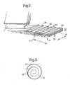
- FIG 2 shows the construction of the batt in more detail.
- the batt has upper and lower faces 30 and 31. It has an end edge 32 formed by cutting the batt transversely and thus exposing the cross section along the X direction. It has side edges 33 and 34 formed in Figure 3 by the edges of the cross lapping. When the batt is cut along the Y direction the cut side edges will show the same inclined arrangement of layers as is apparent in the edges of the batt formed by cross lapping.
- the end edges 32 extend in the X direction and the side edges 33 and 34 extend in the Y direction.
- the web 7 is cross lapped in the X direction as the conveyor 9 travels under the conveying position.
- the end edges 35 in the cut end edge 32 are substantially parallel to the faces 30 and 31 whilst the uncut edges 36 of the layers extend between the side edges 33 and 34 at substantially regularly spaced apart positions, in a zig zag pattern.
- Figure 3 is an end view of a roll and shows the edge 32 of the rolled and compressed batt held compressed in the roll by plastic wrapping 37 which is interleaved in the roll and secured on itself at position 37, so as to hold the roll in its compressed rolled configuration.
- the conveyor 9 carries the batt through a curing oven which can be a conventional construction except that it has to be at least as wide as X.
- the conveyor also carries the batt through conventional cutting systems and rolling systems so as to cut the continuous batt into elongated strips which may have a length of X (more than 3 metres) and a width which is usually less than this.
Landscapes
- Engineering & Computer Science (AREA)
- Textile Engineering (AREA)
- Chemical & Material Sciences (AREA)
- Inorganic Chemistry (AREA)
- Chemical Kinetics & Catalysis (AREA)
- General Chemical & Material Sciences (AREA)
- Manufacturing & Machinery (AREA)
- Dispersion Chemistry (AREA)
- Nonwoven Fabrics (AREA)
- Reinforced Plastic Materials (AREA)
- Treatment Of Fiber Materials (AREA)
Abstract
Description
- This invention relates to bonded man-made vitreous fibre (MMVF) batts which may be of relatively low density (such as 5 to 50kg/m3) and in particular to elongated pieces cut from such batts and supplied to the user as a compressed packaged roll.
- One conventional way of producing such batts involves fiberising mineral melt on a centrifugal spinning apparatus and thereby forming a cloud of fibres entrained in air, including curable binder in the cloud, carrying the cloud forwards from the spinner in a stream of air, collecting the cloud of fibres as a primary web on a substantially continuous moving collector, transporting the web to a cross-lapping position, cross-lapping a plurality of layers of the web while substantially continuously conveying the resultant continuous batt from the cross-lapping position, curing the binder by passing the batt through a curing oven and cutting the continuous batt into elongated pieces before, during or after curing, and compressing and packaging the elongated pieces of batt as rolls.
- The continuous batt can be considered as having upper and lower faces which extend in the X and Y axes or directions with the X direction being the width of the batt as it is collected and the Y direction being the length of the continuous batt as it is collected and carried away from the cross lapping position.
- The quality of the final product tends to deteriorate as the primary web increases in thickness, and so there is an incentive for the primary web to have reduced thickness. However reducing the thickness of the primary web results in reduced productivity (tons per hour) unless either the web is made wider than usual or the web is made to travel faster than usual. The normal maximum width of the primary web is 2 metres, although widths of webs (made by other methods) of up to 2.5 metres are mentioned in DE 3501897 A and up to 4 metres in WO 99/51535 A. Increasing the speed of travel of the web has the disadvantage of increasing the frequency of reciprocation of the cross lapping apparatus, and this causes engineering problems. It would be desirable to achieve increased productivity whilst minimising or avoiding these problems and whilst maintaining quality.
- Although the continuous bonded batt may be used in various forms, most continuous batt is converted into elongated pieces of batt usually having a length greater than the width.
- The normal width of the continuous batt in the X direction is up to 2 metres (although a width of up to 2.5 metres is described in DE 3501897 for batts made by different fiberising techniques) with the result that the maximum length of pieces cut from the batt is normally 2 metres if the pieces are cut transversely, along the X direction. The cut pieces usually have a shorter dimension in the Y direction and so have a width below 2 metres. Because the maximum length in the X direction is, in normal practice, 2 metres, this curtails the type of products which can be made by cutting in this direction. In particular, transverse cutting along the X direction cannot provide elongated pieces having a length above 2 metres.
- However it is often desired to provide elongated pieces of batt which have a length greater than 2 metres, and to supply them in the form of packaged compressed rolls. It is then necessary to cut them from the batt so that the length direction of the ultimate pieces extends in the Y direction of the continuous batt, ie. the direction of travel of the continuous batt as it is being collected from the cross lapper. These cut batts have a shorter dimension in the X direction. Unfortunately pieces cut in this manner have a lower tensile strength in the Y direction than pieces whose major length extends in the X direction.
- It would be desirable co produce long pieces which are cut from continuous batt and which have increased tensile strength in their length direction.
- Space is often a restricting factor in the design of production lines for the production of mineral fibres, because of the need to provide, in sequence, the furnace, the spinner or spinners, the collector, the cross lapper, the batt conveyor a curing oven, and cutting arrangements for cutting the batt into pieces, before, during or after curing. The curing oven in particular has a considerable length. If productivity is increased by increasing the speed of travel of the continuous batt then the length of the oven has to be increased even further and this places a severe restriction in the ability to increase the productivity of existing plants or to install new plants having high levels of productivity. It would be desirable to avoid the use of curing ovens which have to be so long.
- The present invention simultaneously solves all these problems.
- According to the invention we provide an elongated, bonded man-made vitreous fibre (MMVF) batt which has a length direction X and a width direction Y and which has upper and lower faces which extend in the X and Y direction and wherein the batt is formed of a compressed and cured intermeshed stack of layers each of which is formed of air laid MMVF primary web which includes a bonding agent and wherein,
each layer is substantially parallel to the faces when viewed in cross section along the X direction,
the layers are regularly displaced relative to each other in zig-zag fashion in the Y direction, and
each layer is inclined to the faces when viewed in cross section along the Y direction,
characterised in that the layers between the faces extend as continuous layers throughout the X direction, the length in the X direction is at least 3 metres and is greater than the width in the Y direction and the batt is in the form of a compressed and packaged roll whose axis extends in the Y direction. - Preferably the length of the batt in the X direction is at least 4 metres, for instance as much as 6 or even 8 metres.
- The length in the X direction is usually at least two times longer than the width in the Y direction.
- The products of the invention are made by fiberising mineral melt on a centrifugal fiberising apparatus and thereby forming a cloud of fibres entrained in air,
including curable binder in the cloud,
carrying the cloud forwards from the spinner in a stream of air,
collecting the cloud of fibres as a web on a substantially continuously moving collector,
transporting the web to a cross lapping position,
cross lapping a plurality of layers of the web while substantially continuously conveying the resultant continuous batt away from the cross lapping position along the Y direction of the batt,
curing the binder by passing the batt through a curing oven, and
cutting the continuous batt along the X direction (transverse to the Y direction of the continuous batt) into pieces before, during or after curing, and
packaging each piece as a compressed roll,
and in this process the cross lapped continuous batt and each of the pieces has a length in the X direction of, and the width of the curing oven is, at least 3 metres and the width of each of the pieces in the Y direction is less than the length in the X direction. - Thus, in the invention, the cross lapping is conducted to produce a continuous batt which is wider (in the X direction) than usual, and in particular is at least 3 metres wide and often 4 metres up to 6 metres or even 8 metres wide, and this very wide batt is then cut transversely.
- As a result of the increased width of the continuous batt, the frequency of reciprocation of the cross lapper is reduced (at constant web speed), or the frequency does not have to be increased despite increased web speed. This therefore reduces the engineering problems associated with increasing the web speed of the primary web. Thus it is possible to increase productivity (tons per hour) or increase quality by reducing web thickness (or both) without having to increase the frequency of cross-lapper reciprocation.
- As a result of the continuous batt being wider than conventional, the length of the curing oven can be reduced. Thus increased production can be achieved by a fast primary web speed and a wide batt, without the need to increase the length of the curing oven unacceptably. Instead, the curing oven merely needs to be made wider, and in many plants this is a significantly preferred option compared to increasing the length of the oven.
- In the invention, the batt is cut transversely to provide elongated pieces having a dimension in the X direction of at least 3 metres and generally at least 4 metres and with a lesser dimension in the Y direction, for instance up to 1 metre or 2 metres.
- The product of the invention is a compressed and packaged roll which, when unwound, has better tensile strength in the length direction than conventional roll products having a length of at least 3 or 4 metres, since these conventional products have their major length extending in the Y direction. In the invention, the axis of the roll extends along the Y axis, ie. transverse to the length direction of the initial batt.
- The elongated pieces are rolled into compressed and packaged rolls in conventional manner. For instance each piece may be rolled tight with plastic film trapped between the layers of the roll, at least towards the end of the piece, and then sealed to itself after rolling, thereby trapping the roll in an envelope of plastic film. Other conventional methods of packaging the roll in its compressed state can be used.
- The amount of compression of the roll is generally such that the thickness and volume of the roll is 10 to 50% of the norm volume of the batt. The extent of compression is typically from about 50% to about 90% based on the volume of the batt.
- When the packaging is removed, the roll unwinds and expands back towards its original thickness. After the unwound batt has had an opportunity to equilibrate to a final thickness, and therefore a final density, the thickness is generally at least 50mm and usually at least 80 to 100mm. It is frequently up to 180 or 220mm and can be up to 250mm. The thickness of the batt before being compressed and rolled is likewise usually within the range 50mm to 250mm. Usually the thickness before rolling and compression is 5 to 20%, often around 10%, more than the desired thickness after unrolling and equilibration.
- In this specification, thickness is determined by laying the product on a hard flat surface, laying a 200mm x 200mm pressure plate on the surface so as to apply a pressure of 50Pa and measuring the separation between the supporting surface and the plate. The measured thickness is the average of values taken at a number of points . The number of points is 5 when the roll is 2 metres long, 7 when 3 metres long and 9 when 4 metres long, with the points being distributed uniformly over the width of the roll but excluding the outer 150mm of the width.
- The products of the invention usually have a nominal density of 5 to 50kg/m3, and generally at least 15 or 20kg/m3 up to 40 or 45kg/m3. Preferably the product after unrolling and equilibrating has a density in these ranges. The density is derived by calculation from the thickness, measured as above, and measurements of the surface area of the unrolled material and its mass.
- Conventional compressed, low density. MMVF rolls of provide a tensile strength of 3 to 4kN/m2 in the length direction (along the Y axis) (indexed to 30kg/m3 density and ignition loss 1.4%) but in the invention typical values for slabs can be from 6 to 8 kN/m2 in the length direction because the length direction is along the X direction during initial manufacture of the batt which is cut to provide the elongated pieces.
- It is preferred that the primary web is as described in our application GB 0019999.2 filed 14 August 2000 and in our PCT application WO 01/23312 A filed even date herewith, wherein the primary web also has a width of, generally, at least 3 metres and preferably 4 to 8 metres.
- Although the invention can be applied to mineral fibres made by any centrifugal technique, the fibres are preferably made using one more centrifugal cascade spinners each comprising a first rotor and one or more subsequent rotors which rotate about the substantially horizontal axis and thereby form the cloud of fibres entrained in air.
- Suitable apparatus and techniques for forming the fibres are described in, for instance, WO 92/06047 A, WO 92/12939 A, WO 92/12.940 A, -WO 96/38391 A and WO 99/51535 A.
- The invention is illustrated in the accompanying drawings in which
- Figure 1 is a diagrammatic illustration of an apparatus and process for forming the batt.
- Figure 2 is a perspective view of the batt during manufacture and
- Figure 3 is an end view of a roll according to the invention.
- Referring to Figure 1, three
cascade spinners collector 5, whereby the fibres are deposited as aweb 7 which is carried to a cross lapper 8 by which the web is cross lapped on to a conveyor 9, thereby forming abatt 10 which is continuously conveyed away from the cross lapping position. - The conveyer 9 and the batt has a dimension X of at least 3 metres, usually 4 to 8 metres.
- The details of the air supplies and the construction of the chamber may be as described in more detail in WO 96/36391 A.
- The
batt 10 is passed through rollers or the like to compress it and cause intermeshing of the individual layers in the batt and is then passed through a curing oven to cure binder which is sprayed into the cloud of fibres from thecascade spinners - The
collector 5 and theweb 7 can be, for instance, 2 metres wide but are preferably 3 or 4 metres wide, up to 7 or 8 metres wide. The angle of thecollector 5. to the horizontal can be about 30°, as shown in the drawings, but is preferably 45 to 90°, often around 50 to 80°. The collecting chamber is substantially closed as described in WO 96/38391 A. The collector can be a cylindrical drum mounted with its axis transverse to the direction of travel of the web. Instead of travelling away from the spinners, the collector can travel towards the spinners for instance as described in WO 01/23314 A. - Figure 2 shows the construction of the batt in more detail. The batt has upper and lower faces 30 and 31. It has an
end edge 32 formed by cutting the batt transversely and thus exposing the cross section along the X direction. It has side edges 33 and 34 formed in Figure 3 by the edges of the cross lapping. When the batt is cut along the Y direction the cut side edges will show the same inclined arrangement of layers as is apparent in the edges of the batt formed by cross lapping. The end edges 32 extend in the X direction and the side edges 33 and 34 extend in the Y direction. - The
web 7 is cross lapped in the X direction as the conveyor 9 travels under the conveying position. As a result it can be seen that the end edges 35 in thecut end edge 32 are substantially parallel to thefaces uncut edges 36 of the layers extend between the side edges 33 and 34 at substantially regularly spaced apart positions, in a zig zag pattern. - Figure 3 is an end view of a roll and shows the
edge 32 of the rolled and compressed batt held compressed in the roll by plastic wrapping 37 which is interleaved in the roll and secured on itself atposition 37, so as to hold the roll in its compressed rolled configuration. - Although it is not shown in Figure 1, the conveyor 9 carries the batt through a curing oven which can be a conventional construction except that it has to be at least as wide as X. The conveyor also carries the batt through conventional cutting systems and rolling systems so as to cut the continuous batt into elongated strips which may have a length of X (more than 3 metres) and a width which is usually less than this.
Claims (8)
- An elongated, bonded, man-made vitreous fibre batt which has a length direction X and a width direction Y and has upper and lower faces (30,31) which extend in the X and Y directions and wherein the batt is formed of a compressed and cured intermeshed stack of layers (7) each of which is formed of air laid man-made vitreous fibre primary web (7) which includes a bonding agent and wherein
each layer (7) is substantially parallel to the faces when viewed in cross section along the X direction,
the layers (7) are regularly displaced relative to each other in the Y direction,
each layer (7) is inclined to the faces when viewed in cross section along the Y direction,
characterised that the layers (7) between the faces (30,31) extend as continuous layers throughout the X direction,
the length in the direction X is at least 3 metres and is greater than the width in the direction Y,
and the batt is in the form of a compressed and packaged roll whose axis extends in the Y direction. - A batt according to claim 1 in which the X direction has a length of 4 to 8 metres.
- A batt according claim 1 in which each layer in the batt has a weight of below 550 g/m2, preferably 100 to 400 g/m2.
- A batt according to any preceding claim and which has, after unrolling and equilibration, a thickness of 50 to 250mm (preferably 80 to 180mm) and a density of 5 to 50 kg/m3 (preferably 15 to 40 kg/m3).
- A batt according to any preceding claim in which the length in the direction X is at least twice the width in the direction Y.
- A process for making a batt according to any preceding claim comprising
fiberising mineral melt on a centrifugal fiberising apparatus and thereby forming a cloud of fibres entrained in air,
including curable binder in the cloud,
carrying the cloud forwards from the spinner in a stream of air,
collecting the cloud of fibres as a primary web on a substantially continuously moving collector,
transporting the web to a cross lapping position,
cross lapping a plurality of layers of the web while substantially continuously conveying the resultant continuous batt away from the cross lapping position along the Y direction of the batt,
curing the binder by passing the batt through a curing oven and
cutting the continuous batt along the X direction (transverse to the Y direction of the continuous batt) into pieces before, during or after curing, and
packaging each piece as a compressed roll,
characterised in that the continuous batt and each.of the pieces has a length in the X direction of, and the width of the curing oven is, at least 3 metres, preferably 4 to 8 metres, and the width of each piece in the Y direction is less than the length in the X direction. - A process according to claim 6 in which the primary web has a width of at least 3 metres, preferably 4 to 8 metres.
- A process according to any preceding claim in which the centrifugal fiberising apparatus comprises one or more centrifugal cascade spinners each comprising a first rotor and one or more subsequent rotors each mounted for rotation about a substantially horizontal axis.
Priority Applications (1)
| Application Number | Priority Date | Filing Date | Title |
|---|---|---|---|
| EP01980229A EP1322564B1 (en) | 2000-09-28 | 2001-08-02 | Bonded fibre products |
Applications Claiming Priority (4)
| Application Number | Priority Date | Filing Date | Title |
|---|---|---|---|
| EP00121092 | 2000-09-28 | ||
| EP00121092 | 2000-09-28 | ||
| EP01980229A EP1322564B1 (en) | 2000-09-28 | 2001-08-02 | Bonded fibre products |
| PCT/EP2001/008956 WO2002026649A1 (en) | 2000-09-28 | 2001-08-02 | Bonded fibre products |
Publications (2)
| Publication Number | Publication Date |
|---|---|
| EP1322564A1 EP1322564A1 (en) | 2003-07-02 |
| EP1322564B1 true EP1322564B1 (en) | 2006-10-25 |
Family
ID=8169967
Family Applications (1)
| Application Number | Title | Priority Date | Filing Date |
|---|---|---|---|
| EP01980229A Expired - Lifetime EP1322564B1 (en) | 2000-09-28 | 2001-08-02 | Bonded fibre products |
Country Status (7)
| Country | Link |
|---|---|
| EP (1) | EP1322564B1 (en) |
| AT (1) | ATE343556T1 (en) |
| AU (1) | AU2002212126A1 (en) |
| DE (1) | DE60124127T2 (en) |
| ES (1) | ES2273898T3 (en) |
| SI (1) | SI1322564T1 (en) |
| WO (1) | WO2002026649A1 (en) |
Families Citing this family (1)
| Publication number | Priority date | Publication date | Assignee | Title |
|---|---|---|---|---|
| JP6103506B2 (en) * | 2014-07-22 | 2017-03-29 | 旭ファイバーグラス株式会社 | Inorganic fiber insulation |
Family Cites Families (8)
| Publication number | Priority date | Publication date | Assignee | Title |
|---|---|---|---|---|
| US3740282A (en) * | 1971-02-16 | 1973-06-19 | Celanese Corp | Process for making artificial leather from lapped fibrous structures |
| DE3501897A1 (en) * | 1985-01-22 | 1986-07-24 | Bayer Ag, 5090 Leverkusen | Process for producing a multi-layer fibre mat |
| DK165926B (en) * | 1990-12-07 | 1993-02-08 | Rockwool Int | PROCEDURE FOR THE MANUFACTURE OF INSULATION PLATES COMPOSED BY INVOLVED CONNECTED STABLE MINERAL FIBER ELEMENTS |
| GB9509782D0 (en) * | 1995-05-15 | 1995-07-05 | Rockwool Int | Man-made vitreous fibre products and processes and apparatus for their production |
| GB9509813D0 (en) * | 1995-05-15 | 1995-07-05 | Rockwool Int | Method and apparatus for the manufacture of man-made vitreous fibre products |
| DE69913669T2 (en) * | 1998-03-19 | 2004-09-30 | Rockwool International A/S | METHOD AND DEVICE FOR PRODUCING A MINERAL FIBER PRODUCT, ITS USE AND A PRODUCT MANUFACTURED THEREFOR |
| PL191294B1 (en) * | 1998-04-06 | 2006-04-28 | Rockwool Int | Man-made vitreous fibre batts and their production |
| MY127992A (en) * | 1999-09-28 | 2007-01-31 | Rockwool Int | Processes and apparatus for the production of man-made vitreous fibre products |
-
2001
- 2001-08-02 ES ES01980229T patent/ES2273898T3/en not_active Expired - Lifetime
- 2001-08-02 EP EP01980229A patent/EP1322564B1/en not_active Expired - Lifetime
- 2001-08-02 DE DE60124127T patent/DE60124127T2/en not_active Expired - Lifetime
- 2001-08-02 AT AT01980229T patent/ATE343556T1/en active
- 2001-08-02 WO PCT/EP2001/008956 patent/WO2002026649A1/en not_active Ceased
- 2001-08-02 AU AU2002212126A patent/AU2002212126A1/en not_active Abandoned
- 2001-08-02 SI SI200130674T patent/SI1322564T1/en unknown
Also Published As
| Publication number | Publication date |
|---|---|
| EP1322564A1 (en) | 2003-07-02 |
| SI1322564T1 (en) | 2007-04-30 |
| ATE343556T1 (en) | 2006-11-15 |
| DE60124127D1 (en) | 2006-12-07 |
| ES2273898T3 (en) | 2007-05-16 |
| AU2002212126A1 (en) | 2002-04-08 |
| WO2002026649A1 (en) | 2002-04-04 |
| DE60124127T2 (en) | 2007-09-06 |
Similar Documents
| Publication | Publication Date | Title |
|---|---|---|
| CA1213505A (en) | Manufacturing a laminated pack of mineral fibers | |
| US2409066A (en) | Manufacture of felted products | |
| JPH0351325A (en) | Method and apparatus for manufacturing mineral fiber fleece from rock wool | |
| CZ282594B6 (en) | Process for producing insulating boards | |
| US5620497A (en) | Wool pack forming apparatus using high speed rotating drums and low frequency sound distribution | |
| US4835045A (en) | Fiber glass board and method of manufacture | |
| CS9100817A2 (en) | Method and device for felt of mineral fibres treatment | |
| EP1086054B2 (en) | Apparatus for forming a man-made vitreous fibre web | |
| EP0759102B1 (en) | Direct forming method of collecting long wool fibers | |
| EP0825965B1 (en) | Method and apparatus for the manufacture of man-made vitreous fibre products | |
| EP1228010B1 (en) | Compressed, packaged roll of MMVF batt and fabrication process of roll and MMVF web | |
| US5041178A (en) | Method of manufacturing a fibrous board | |
| EP1064438B1 (en) | Process and apparatus for the preparation of a mineral fibre product, uses of it and such product | |
| EA000397B1 (en) | Process and apparatus for the production of a mineral fibreboard | |
| EP1322564A1 (en) | Bonded fibre products | |
| EP0766758B1 (en) | Low frequency sound distribution of rotary fiberizer veils | |
| EP1456444B2 (en) | Mineral fibre batts and their production | |
| CA2028768A1 (en) | Method and apparatus for the manufacture of mineral wool plates | |
| ES2290791T3 (en) | PROCEDURE AND DEVICE FOR THE MANUFACTURE OF INSULATING MATERIALS IN THE FORM OF BANDS OR PLATES FROM MINERAL FIBERS. | |
| CA1281569C (en) | Papermaker's felt utilizing special web-making techniques to avoid vibration | |
| EP1456451B1 (en) | Mineral fibre batts | |
| EP1228012B1 (en) | Processes and apparatus for the production of man-made vitreous fibre products | |
| NO171924B (en) | PROCEDURE FOR CONTINUOUS PREPARATION OF FIBER INSULATION COAT AND DEVICE FOR IMPLEMENTING THE PROCEDURE |
Legal Events
| Date | Code | Title | Description |
|---|---|---|---|
| PUAI | Public reference made under article 153(3) epc to a published international application that has entered the european phase |
Free format text: ORIGINAL CODE: 0009012 |
|
| 17P | Request for examination filed |
Effective date: 20030122 |
|
| AK | Designated contracting states |
Designated state(s): AT BE CH CY DE DK ES FI FR GB GR IE IT LI LU MC NL PT SE TR |
|
| AX | Request for extension of the european patent |
Extension state: AL LT LV MK RO SI |
|
| 17Q | First examination report despatched |
Effective date: 20050407 |
|
| GRAP | Despatch of communication of intention to grant a patent |
Free format text: ORIGINAL CODE: EPIDOSNIGR1 |
|
| GRAS | Grant fee paid |
Free format text: ORIGINAL CODE: EPIDOSNIGR3 |
|
| GRAA | (expected) grant |
Free format text: ORIGINAL CODE: 0009210 |
|
| AK | Designated contracting states |
Kind code of ref document: B1 Designated state(s): AT BE CH CY DE DK ES FI FR GB GR IE IT LI LU MC NL PT SE TR |
|
| AX | Request for extension of the european patent |
Extension state: SI |
|
| PG25 | Lapsed in a contracting state [announced via postgrant information from national office to epo] |
Ref country code: IT Free format text: LAPSE BECAUSE OF FAILURE TO SUBMIT A TRANSLATION OF THE DESCRIPTION OR TO PAY THE FEE WITHIN THE PRESCRIBED TIME-LIMIT;WARNING: LAPSES OF ITALIAN PATENTS WITH EFFECTIVE DATE BEFORE 2007 MAY HAVE OCCURRED AT ANY TIME BEFORE 2007. THE CORRECT EFFECTIVE DATE MAY BE DIFFERENT FROM THE ONE RECORDED. Effective date: 20061025 Ref country code: NL Free format text: LAPSE BECAUSE OF FAILURE TO SUBMIT A TRANSLATION OF THE DESCRIPTION OR TO PAY THE FEE WITHIN THE PRESCRIBED TIME-LIMIT Effective date: 20061025 Ref country code: LI Free format text: LAPSE BECAUSE OF FAILURE TO SUBMIT A TRANSLATION OF THE DESCRIPTION OR TO PAY THE FEE WITHIN THE PRESCRIBED TIME-LIMIT Effective date: 20061025 Ref country code: BE Free format text: LAPSE BECAUSE OF FAILURE TO SUBMIT A TRANSLATION OF THE DESCRIPTION OR TO PAY THE FEE WITHIN THE PRESCRIBED TIME-LIMIT Effective date: 20061025 Ref country code: CH Free format text: LAPSE BECAUSE OF FAILURE TO SUBMIT A TRANSLATION OF THE DESCRIPTION OR TO PAY THE FEE WITHIN THE PRESCRIBED TIME-LIMIT Effective date: 20061025 |
|
| REG | Reference to a national code |
Ref country code: GB Ref legal event code: FG4D |
|
| REG | Reference to a national code |
Ref country code: CH Ref legal event code: EP |
|
| REG | Reference to a national code |
Ref country code: IE Ref legal event code: FG4D |
|
| REF | Corresponds to: |
Ref document number: 60124127 Country of ref document: DE Date of ref document: 20061207 Kind code of ref document: P |
|
| PG25 | Lapsed in a contracting state [announced via postgrant information from national office to epo] |
Ref country code: DK Free format text: LAPSE BECAUSE OF FAILURE TO SUBMIT A TRANSLATION OF THE DESCRIPTION OR TO PAY THE FEE WITHIN THE PRESCRIBED TIME-LIMIT Effective date: 20070125 |
|
| REG | Reference to a national code |
Ref country code: SE Ref legal event code: TRGR |
|
| PG25 | Lapsed in a contracting state [announced via postgrant information from national office to epo] |
Ref country code: PT Free format text: LAPSE BECAUSE OF FAILURE TO SUBMIT A TRANSLATION OF THE DESCRIPTION OR TO PAY THE FEE WITHIN THE PRESCRIBED TIME-LIMIT Effective date: 20070326 |
|
| NLV1 | Nl: lapsed or annulled due to failure to fulfill the requirements of art. 29p and 29m of the patents act | ||
| REG | Reference to a national code |
Ref country code: CH Ref legal event code: PL |
|
| REG | Reference to a national code |
Ref country code: ES Ref legal event code: FG2A Ref document number: 2273898 Country of ref document: ES Kind code of ref document: T3 |
|
| ET | Fr: translation filed | ||
| PLBE | No opposition filed within time limit |
Free format text: ORIGINAL CODE: 0009261 |
|
| STAA | Information on the status of an ep patent application or granted ep patent |
Free format text: STATUS: NO OPPOSITION FILED WITHIN TIME LIMIT |
|
| 26N | No opposition filed |
Effective date: 20070726 |
|
| PG25 | Lapsed in a contracting state [announced via postgrant information from national office to epo] |
Ref country code: GR Free format text: LAPSE BECAUSE OF FAILURE TO SUBMIT A TRANSLATION OF THE DESCRIPTION OR TO PAY THE FEE WITHIN THE PRESCRIBED TIME-LIMIT Effective date: 20070126 Ref country code: MC Free format text: LAPSE BECAUSE OF NON-PAYMENT OF DUE FEES Effective date: 20070831 |
|
| PG25 | Lapsed in a contracting state [announced via postgrant information from national office to epo] |
Ref country code: IE Free format text: LAPSE BECAUSE OF NON-PAYMENT OF DUE FEES Effective date: 20070802 |
|
| PGFP | Annual fee paid to national office [announced via postgrant information from national office to epo] |
Ref country code: GB Payment date: 20080813 Year of fee payment: 8 |
|
| PG25 | Lapsed in a contracting state [announced via postgrant information from national office to epo] |
Ref country code: LU Free format text: LAPSE BECAUSE OF NON-PAYMENT OF DUE FEES Effective date: 20070802 Ref country code: CY Free format text: LAPSE BECAUSE OF FAILURE TO SUBMIT A TRANSLATION OF THE DESCRIPTION OR TO PAY THE FEE WITHIN THE PRESCRIBED TIME-LIMIT Effective date: 20061025 |
|
| PG25 | Lapsed in a contracting state [announced via postgrant information from national office to epo] |
Ref country code: TR Free format text: LAPSE BECAUSE OF FAILURE TO SUBMIT A TRANSLATION OF THE DESCRIPTION OR TO PAY THE FEE WITHIN THE PRESCRIBED TIME-LIMIT Effective date: 20061025 |
|
| PGFP | Annual fee paid to national office [announced via postgrant information from national office to epo] |
Ref country code: ES Payment date: 20090902 Year of fee payment: 9 |
|
| PGFP | Annual fee paid to national office [announced via postgrant information from national office to epo] |
Ref country code: FI Payment date: 20090813 Year of fee payment: 9 Ref country code: SE Payment date: 20090806 Year of fee payment: 9 |
|
| GBPC | Gb: european patent ceased through non-payment of renewal fee |
Effective date: 20090802 |
|
| PG25 | Lapsed in a contracting state [announced via postgrant information from national office to epo] |
Ref country code: GB Free format text: LAPSE BECAUSE OF NON-PAYMENT OF DUE FEES Effective date: 20090802 |
|
| EUG | Se: european patent has lapsed | ||
| PG25 | Lapsed in a contracting state [announced via postgrant information from national office to epo] |
Ref country code: FI Free format text: LAPSE BECAUSE OF NON-PAYMENT OF DUE FEES Effective date: 20100802 |
|
| REG | Reference to a national code |
Ref country code: ES Ref legal event code: FD2A Effective date: 20111019 |
|
| PG25 | Lapsed in a contracting state [announced via postgrant information from national office to epo] |
Ref country code: ES Free format text: LAPSE BECAUSE OF NON-PAYMENT OF DUE FEES Effective date: 20100803 |
|
| PG25 | Lapsed in a contracting state [announced via postgrant information from national office to epo] |
Ref country code: SE Free format text: LAPSE BECAUSE OF NON-PAYMENT OF DUE FEES Effective date: 20100803 |
|
| REG | Reference to a national code |
Ref country code: DE Ref legal event code: R082 Ref document number: 60124127 Country of ref document: DE Representative=s name: MEISSNER, BOLTE & PARTNER GBR, DE Ref country code: DE Ref legal event code: R082 Ref document number: 60124127 Country of ref document: DE Representative=s name: MEISSNER BOLTE PATENTANWAELTE RECHTSANWAELTE P, DE |
|
| REG | Reference to a national code |
Ref country code: DE Ref legal event code: R082 Ref document number: 60124127 Country of ref document: DE Representative=s name: MEISSNER, BOLTE & PARTNER GBR, DE |
|
| REG | Reference to a national code |
Ref country code: FR Ref legal event code: PLFP Year of fee payment: 16 |
|
| PGFP | Annual fee paid to national office [announced via postgrant information from national office to epo] |
Ref country code: DE Payment date: 20160726 Year of fee payment: 16 Ref country code: IT Payment date: 20160822 Year of fee payment: 16 |
|
| PGFP | Annual fee paid to national office [announced via postgrant information from national office to epo] |
Ref country code: FR Payment date: 20160729 Year of fee payment: 16 Ref country code: AT Payment date: 20160725 Year of fee payment: 16 |
|
| REG | Reference to a national code |
Ref country code: DE Ref legal event code: R119 Ref document number: 60124127 Country of ref document: DE |
|
| REG | Reference to a national code |
Ref country code: AT Ref legal event code: MM01 Ref document number: 343556 Country of ref document: AT Kind code of ref document: T Effective date: 20170802 |
|
| REG | Reference to a national code |
Ref country code: FR Ref legal event code: ST Effective date: 20180430 |
|
| PG25 | Lapsed in a contracting state [announced via postgrant information from national office to epo] |
Ref country code: AT Free format text: LAPSE BECAUSE OF NON-PAYMENT OF DUE FEES Effective date: 20170802 |
|
| REG | Reference to a national code |
Ref country code: SI Ref legal event code: KO00 Effective date: 20180416 |
|
| PG25 | Lapsed in a contracting state [announced via postgrant information from national office to epo] |
Ref country code: DE Free format text: LAPSE BECAUSE OF NON-PAYMENT OF DUE FEES Effective date: 20180301 |
|
| PG25 | Lapsed in a contracting state [announced via postgrant information from national office to epo] |
Ref country code: FR Free format text: LAPSE BECAUSE OF NON-PAYMENT OF DUE FEES Effective date: 20170831 Ref country code: IT Free format text: LAPSE BECAUSE OF NON-PAYMENT OF DUE FEES Effective date: 20170802 |