EP1322265B1 - Fusseinsatz für einen kunstfuss - Google Patents
Fusseinsatz für einen kunstfuss Download PDFInfo
- Publication number
- EP1322265B1 EP1322265B1 EP01960159A EP01960159A EP1322265B1 EP 1322265 B1 EP1322265 B1 EP 1322265B1 EP 01960159 A EP01960159 A EP 01960159A EP 01960159 A EP01960159 A EP 01960159A EP 1322265 B1 EP1322265 B1 EP 1322265B1
- Authority
- EP
- European Patent Office
- Prior art keywords
- spring
- insert according
- foot
- foot insert
- forefoot
- Prior art date
- Legal status (The legal status is an assumption and is not a legal conclusion. Google has not performed a legal analysis and makes no representation as to the accuracy of the status listed.)
- Expired - Lifetime
Links
- 210000002683 foot Anatomy 0.000 claims abstract description 68
- 210000004744 fore-foot Anatomy 0.000 claims abstract description 46
- 238000005096 rolling process Methods 0.000 claims description 15
- 210000003423 ankle Anatomy 0.000 claims description 9
- 239000002537 cosmetic Substances 0.000 claims description 4
- 230000001154 acute effect Effects 0.000 claims description 3
- 239000002131 composite material Substances 0.000 claims description 3
- 239000000835 fiber Substances 0.000 claims description 3
- 239000002861 polymer material Substances 0.000 claims description 3
- 230000000694 effects Effects 0.000 claims description 2
- 210000000544 articulatio talocruralis Anatomy 0.000 claims 1
- 230000015572 biosynthetic process Effects 0.000 claims 1
- 210000000474 heel Anatomy 0.000 description 17
- 238000005452 bending Methods 0.000 description 4
- 238000002266 amputation Methods 0.000 description 3
- 230000000750 progressive effect Effects 0.000 description 2
- 230000005540 biological transmission Effects 0.000 description 1
- 210000000459 calcaneus Anatomy 0.000 description 1
- 230000006835 compression Effects 0.000 description 1
- 238000007906 compression Methods 0.000 description 1
- 238000010276 construction Methods 0.000 description 1
- 238000004146 energy storage Methods 0.000 description 1
- 230000002349 favourable effect Effects 0.000 description 1
- 238000000034 method Methods 0.000 description 1
Images

Classifications
-
- A—HUMAN NECESSITIES
- A61—MEDICAL OR VETERINARY SCIENCE; HYGIENE
- A61F—FILTERS IMPLANTABLE INTO BLOOD VESSELS; PROSTHESES; DEVICES PROVIDING PATENCY TO, OR PREVENTING COLLAPSING OF, TUBULAR STRUCTURES OF THE BODY, e.g. STENTS; ORTHOPAEDIC, NURSING OR CONTRACEPTIVE DEVICES; FOMENTATION; TREATMENT OR PROTECTION OF EYES OR EARS; BANDAGES, DRESSINGS OR ABSORBENT PADS; FIRST-AID KITS
- A61F2/00—Filters implantable into blood vessels; Prostheses, i.e. artificial substitutes or replacements for parts of the body; Appliances for connecting them with the body; Devices providing patency to, or preventing collapsing of, tubular structures of the body, e.g. stents
- A61F2/50—Prostheses not implantable in the body
- A61F2/60—Artificial legs or feet or parts thereof
- A61F2/66—Feet; Ankle joints
-
- A—HUMAN NECESSITIES
- A61—MEDICAL OR VETERINARY SCIENCE; HYGIENE
- A61F—FILTERS IMPLANTABLE INTO BLOOD VESSELS; PROSTHESES; DEVICES PROVIDING PATENCY TO, OR PREVENTING COLLAPSING OF, TUBULAR STRUCTURES OF THE BODY, e.g. STENTS; ORTHOPAEDIC, NURSING OR CONTRACEPTIVE DEVICES; FOMENTATION; TREATMENT OR PROTECTION OF EYES OR EARS; BANDAGES, DRESSINGS OR ABSORBENT PADS; FIRST-AID KITS
- A61F2/00—Filters implantable into blood vessels; Prostheses, i.e. artificial substitutes or replacements for parts of the body; Appliances for connecting them with the body; Devices providing patency to, or preventing collapsing of, tubular structures of the body, e.g. stents
- A61F2/50—Prostheses not implantable in the body
- A61F2002/5003—Prostheses not implantable in the body having damping means, e.g. shock absorbers
-
- A—HUMAN NECESSITIES
- A61—MEDICAL OR VETERINARY SCIENCE; HYGIENE
- A61F—FILTERS IMPLANTABLE INTO BLOOD VESSELS; PROSTHESES; DEVICES PROVIDING PATENCY TO, OR PREVENTING COLLAPSING OF, TUBULAR STRUCTURES OF THE BODY, e.g. STENTS; ORTHOPAEDIC, NURSING OR CONTRACEPTIVE DEVICES; FOMENTATION; TREATMENT OR PROTECTION OF EYES OR EARS; BANDAGES, DRESSINGS OR ABSORBENT PADS; FIRST-AID KITS
- A61F2/00—Filters implantable into blood vessels; Prostheses, i.e. artificial substitutes or replacements for parts of the body; Appliances for connecting them with the body; Devices providing patency to, or preventing collapsing of, tubular structures of the body, e.g. stents
- A61F2/50—Prostheses not implantable in the body
- A61F2/5044—Designing or manufacturing processes
- A61F2002/5055—Reinforcing prostheses by embedding particles or fibres during moulding or dipping, e.g. carbon fibre composites
-
- A—HUMAN NECESSITIES
- A61—MEDICAL OR VETERINARY SCIENCE; HYGIENE
- A61F—FILTERS IMPLANTABLE INTO BLOOD VESSELS; PROSTHESES; DEVICES PROVIDING PATENCY TO, OR PREVENTING COLLAPSING OF, TUBULAR STRUCTURES OF THE BODY, e.g. STENTS; ORTHOPAEDIC, NURSING OR CONTRACEPTIVE DEVICES; FOMENTATION; TREATMENT OR PROTECTION OF EYES OR EARS; BANDAGES, DRESSINGS OR ABSORBENT PADS; FIRST-AID KITS
- A61F2/00—Filters implantable into blood vessels; Prostheses, i.e. artificial substitutes or replacements for parts of the body; Appliances for connecting them with the body; Devices providing patency to, or preventing collapsing of, tubular structures of the body, e.g. stents
- A61F2/50—Prostheses not implantable in the body
- A61F2002/5081—Additional features
- A61F2002/5083—Additional features modular
-
- A—HUMAN NECESSITIES
- A61—MEDICAL OR VETERINARY SCIENCE; HYGIENE
- A61F—FILTERS IMPLANTABLE INTO BLOOD VESSELS; PROSTHESES; DEVICES PROVIDING PATENCY TO, OR PREVENTING COLLAPSING OF, TUBULAR STRUCTURES OF THE BODY, e.g. STENTS; ORTHOPAEDIC, NURSING OR CONTRACEPTIVE DEVICES; FOMENTATION; TREATMENT OR PROTECTION OF EYES OR EARS; BANDAGES, DRESSINGS OR ABSORBENT PADS; FIRST-AID KITS
- A61F2/00—Filters implantable into blood vessels; Prostheses, i.e. artificial substitutes or replacements for parts of the body; Appliances for connecting them with the body; Devices providing patency to, or preventing collapsing of, tubular structures of the body, e.g. stents
- A61F2/50—Prostheses not implantable in the body
- A61F2/60—Artificial legs or feet or parts thereof
- A61F2/66—Feet; Ankle joints
- A61F2002/6614—Feet
- A61F2002/6657—Feet having a plate-like or strip-like spring element, e.g. an energy-storing cantilever spring keel
- A61F2002/6664—Dual structures made of two connected cantilevered leaf springs
Definitions
- the invention relates to a resilient foot insert for an artificial foot.
- a jointless prosthetic foot having a resilient foot insert receiving and transmitting the prosthetic loads is e.g. in DE 40 37 928 A1 and EP 0 648 479 A1.
- Elastic foot inserts also show US Pat. Nos. 4,959,073, 5,549,711 and 5,800,570, EP 0 884 033 A2 and DE 298 20 904 U1.
- the invention has for its object to develop a resilient foot insert for a prosthetic foot, which has a progressive ankle torque curve, energy storage and an elastic ML (MediaI / Lateral) -Mobility allows.
- a resilient foot insert for an artificial foot consisting of at least two interconnected springs, which - in the unloaded state - together enclose an approximately triangular jounce space in side view, wherein the upper, approximately roof-shaped spring in the rooftop area an adapter connection and thereof starting from a concave downward bent, extending into the heel area heel limb (hereinafter “heel”) and a concave down bent, extending into the forefoot area forefoot leg (hereinafter “forefoot”), the free leg ends with a separate, den Boundary spring are bounding downwards bounding base spring, which cooperates with a rolling contour so that during the rolling process at the beginning of Vorfußbelastung the force is first introduced in the ball area, wherein the forefoot spring and the base spring are designed in terms of shape and bending elasticity so that under the action of increasing load in the forefoot area in this area forefoot and base spring by respective bending successive create each other.
- this foot insert is inventively characterized by such a design of the forefoot spring and base spring in shape and elasticity that comes with increasing load in the forefoot area in this area to a successive investment of forefoot and base spring together.
- the forefoot spring causes a progressive Knöchetmomentenvertank by this successive investment in the base spring.
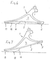
- the force is initially introduced in the ball area at the beginning of Vorfußbelastung, whereby the base spring between the heel and forefoot spring is mounted and undergoes a three-point bend. There is then a series connection of the bending stiffnesses of forefoot and base spring (see also the illustration in FIG. 6). In the further course of the step, the foot rolls off and increasingly loaded directly the forefoot spring.
- the base spring additionally supports the moments in the forefoot spring and is now bent in the opposite direction. There is a parallel connection of the bending stiffnesses (see also the illustration in FIG. 7).
- the process of Vorfußbeias tion is thus characterized by an increasing stiffening or progression of the spring behavior.
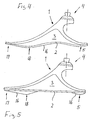
- the contact points of the prosthetic foot with the floor or shoe determine the location of the force application. This affects the biomechanics of the foot, but also controls the load on the mechanical structures of the foot. Since the foot undergoes an angular movement during the stance phase, the force introduction point can be controlled by means of a suitable unwinding geometry. It is irrelevant whether this geometry in the shape of the base spring is integrated (see, for example, Figure 4), is applied to the base spring (see Figure 5) or an expression of the surrounding cosmetic sheath is (see Figure 1). In all these cases, the base spring cooperates on the underside with a rolling contour, which rises from the toe area to the ball area downwards, then falls back upwards and is formed in the heel area down bead-shaped.
- the characteristic of the foot can be changed in a targeted manner by using base springs of different stiffnesses.
- the connections between the base spring and the two leg ends of the upper spring are designed detachable.
- ML movement By reducing the torsional rigidity of the forefoot spring, ML movement can be generated.
- This can be realized by virtue of the fact that the forefoot spring has an elongated recess extending in its longitudinal direction, or else in that the forefoot spring is split in its longitudinal direction into two part-springs.
- the momentary pole of the ML rotation lies in a physiologically meaningful way above the ground plane, while a rotation about the leg longitudinal axis is hardly possible.
- At least one of the springs preferably consists of a polymer material, which is expediently a fiber composite material.
- a fiber composite material With a fiber composite material, the force can be introduced into the springs then make cheaper if the springs are made individually, especially if parts of the adapter are part of one of the springs.
- the forefoot spring and the heel spring form separate components which are connected to one another in the region of the adapter connection.
- at least the dome of the adapter connection is an integral part of the forefoot spring. In this case, a particularly favorable in terms of power transmission construction is given when the forefoot spring is supported in the region of its adapter connection on the upper leg end of the heel spring.
- the adapter port is positioned anterior of the ankle area of a natural foot and one with the base spring a having acute angle enclosing pad.
- the space below the prosthesis shaft can be used as a compression space for the heel bone.
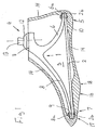
- FIG. 1 shows a resilient foot insert for an artificial foot.
- the foot insert consists of an upper, approximately roof-shaped spring 1, which encloses an approximately triangular jounce space 3 together with a lower base spring 2.
- the upper spring 1 has in its rooftop area an adapter connection 4, from the rear a concave downward bent, extending into the heel area 5 heel spring 6 and forward a concave downwardly bent, extending into the forefoot 7 forefoot spring eighth out.
- the front free leg end 8a of the forefoot spring 8 is connected to the front end 2a of the base spring 2, while the rear free leg end 6a of the heel spring 6 is connected to the rear end 2b of the base spring 2.
- the connections between the upper spring 1 and the base spring 2 can be configured as detachable connections 9, 10, as can be seen from FIG.
- the base spring 2 is then interchangeable.
- the adapter connection 4 lies approximately in the ankle region of a natural foot and has a connection surface 11 approximately parallel to the base spring 2.
- the adapter connection 4 comprises a dome 12 and a truncated pyramid 13, which stands with its tip on the dome 12.
- FIG. 1 also shows that the elastic foot insert is surrounded by a cosmetic cover 14.
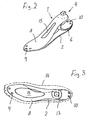
- the forefoot spring 8 has an elongate recess 15 extending in its longitudinal direction.
- the essentially straight base spring 2 cooperates with a rolling contour 16 formed by the underside of the cosmetic casing 14, which rises downwards from the toe region 17 of the synthetic foot to the bale region 18 and then falls back upwards and is formed bead-shaped downwards in the heel region 5 is.
- the base spring 2 is bent directly in the form of the rolling contour 16.
- the rolling contour 16 is applied to the underside of the base spring 2 running approximately straight in the longitudinal direction.
- the upper spring 1 of the foot insert is integrally formed; the adapter connection 4 forms an integral part of this one-piece upper spring 1.
- the heel spring 6 and forefoot spring 8 form separate components which are connected to one another in the region of the adapter connection 4.
- the adapter terminal 4 forms an integral part of the separately formed forefoot spring 8, which is supported in the region of the adapter terminal 4 on the upper, bent back leg end 6b of the heel spring 6, which is formed approximately C-shaped.
- Figure 9 shows a resilient foot insert, which is intended for restorations at very low amputation heights, in particular in Exartikutationen in the ankle of the prosthesis wearer.
- the adapter connection 4 is positioned relative to the embodiment according to FIGS. 1-8 anterior to the ankle area of a natural foot and has a connection surface 11 enclosing an acute angle ⁇ with the base spring 2.
- the adapter connection also includes a dome 12, which allows limited angular adjustments of the indicated by a dotted line shaft 19. This training leads to a large heel walk 20.
Landscapes
- Health & Medical Sciences (AREA)
- Transplantation (AREA)
- Vascular Medicine (AREA)
- Life Sciences & Earth Sciences (AREA)
- Oral & Maxillofacial Surgery (AREA)
- Engineering & Computer Science (AREA)
- Biomedical Technology (AREA)
- Heart & Thoracic Surgery (AREA)
- Orthopedic Medicine & Surgery (AREA)
- Cardiology (AREA)
- Animal Behavior & Ethology (AREA)
- General Health & Medical Sciences (AREA)
- Public Health (AREA)
- Veterinary Medicine (AREA)
- Prostheses (AREA)
- Orthopedics, Nursing, And Contraception (AREA)
- Push-Button Switches (AREA)
Description
- Die Erfindung betrifft einen federelastischen Fußeinsatz für einen Kunstfuß.
- Ein gelenkloser Prothesenfuß mit einem die Prothesenbelastungen aufnehmenden und übertragenden federelastischen Fußeinsatz ist z.B. in der DE 40 37 928 A1 und der EP 0 648 479 A1 offenbart. Elastische Fußeinsätze zeigen auch die US-Patentschriften 4 959 073, 5 549 711 und 5 800 570, die EP 0 884 033 A2 sowie die DE 298 20 904 U1.
- Der Erfindung liegt die Aufgabe zugrunde, einen federelastischen Fußeinsatz für einen Prothesenfuß zu entwickeln, der einen progressiven Knöchelmomentenverlauf aufweist, energiespeichernd wirkt und eine elastische ML(MediaI/Lateral)-Beweglichkeit zulässt.
- Diese Aufgabe wird erfindungsgemäß gelöst durch einen federelastischer Fußeinsatz für einen Kunstfuß, bestehend aus zumindest zwei miteinander verbundenen Federn, die - in unbelastetem Zustand - zusammen in Seitenansicht einen etwa dreiecksförmigen Einfederraum umschließen, wobei die obere, etwa dachförmig ausgebildete Feder im Dachspitzenbereich einen Adapteranschluss und hiervon ausgehend einen konkav nach unten durchgebogenen, sich bis in den Fersenbereich erstreckenden Fersenschenkel (nachfolgend "Fersenfeder") sowie einen konkav nach unten durchgebogenen, sich bis in den Vorfußbereich erstreckenden Vorfußschenkel (nachfolgend "Vorfußfeder") aufweist, deren freien Schenkelenden mit einer separaten, den Einfederraum nach unten begrenzenden biegesteifen Basisfeder verbunden sind, die mit einer Abrollkontur so zusammenwirkt, dass beim Abrollvorgang zu Beginn der Vorfußbelastung die Kraft zunächst im Ballenbereich eingeleitet wird, wobei Vorfußfeder und Basisfeder hinsichtlich Form und Biegeelastizität so ausgelegt sind, dass sich unter Einwirkung einer zunehmenden Belastung im Vorfußbereich in diesem Bereich Vorfuß- und Basisfeder durch jeweilige Biegung sukzessive aneinander anlegen.
- Dabei ist dieser Fußeinsatz erfindungsgemäß gekennzeichnet durch eine solche Auslegung der Vorfußfeder und Basisfeder in Form und Elastizität, dass bei zunehmender Belastung im Vorfußbereich es in diesem Bereich zu einer sukzessiven Anlage der Vorfuß- und Basisfeder aneinander kommt. Die Vorfußfeder bewirkt durch diese sukzessive Anlage an die Basisfeder einen progressiven Knöchetmomentenvertauf. Dabei wird zu Beginn der Vorfußbelastung die Kraft zunächst im Ballenbereich eingeleitet, wodurch die Basisfeder zwischen Fersen- und Vorfußfeder gelagert wird und eine Dreipunktbiegung erfährt. Es besteht dann eine Serienschaltung der Biegesteifigkeiten von Vorfuß- und Basisfeder (siehe hierzu auch die Darstellung in Figur 6). Im weiteren Verlauf des Schrittes rollt der Fuß ab und belastet zunehmend direkt die Vorfußfeder. Die Basisfeder stützt dabei zusätzlich die Momente in der Vorfußfeder ab und wird nun in umgekehrter Richtung gebogen. Es besteht eine Parallelschaltung der Biegesteifigkeiten (siehe hierzu auch die Darstellung in Figur 7). Der Ablauf der Vorfußbeias-tung ist somit von einer zunehmenden Versteifung oder Progression des Federverhaltens geprägt.
- Die Kontaktpunkte des Prothesenfußes mit dem Boden oder Schuh bestimmen den Ort der Krafteinleitung. Dies hat einen Einfluss auf die Biomechanik des Fußes, steuert aber auch die Belastung der mechanischen Strukturen des Fußes. Da der Fuß während der Standphase eine Winkelbewegung erfährt, kann durch eine geeignete Abrollgeometrie der Krafteinleitungspunkt gesteuert werden. Dabei ist es unerheblich, ob diese Geometrie in die Formgebung der Basisfeder integriert ist (siehe z.B. Figur 4), auf die Basisfeder appliziert ist (siehe Figur 5) oder eine Ausprägung der umgebenden Kosmetikhülle ist (siehe Figur 1). In allen diesen Fällen wirkt die Basisfeder unterseitig mit einer Abrollkontur zusammen, die vom Zehenbereich zum Ballenbereich nach unten ansteigt, dann wieder nach oben abfällt und im Fersenbereich nach unten wulstförmig ausgeformt ist.
- Es ist ferner für die angestrebte Wirkung zweckmäßig, wenn das vordere freie Schenkelende der Vorfußfeder mit dem vorderen Ende der Basisfeder verbunden ist, und wenn das hintere freie Schenkelende der Fersenfeder mit dem hinteren Ende der Basisfeder verbunden ist.
- Die Charakteristik des Fußes kann gezielt verändert werden, indem Basisfedern verschiedener Steifigkeiten eingesetzt werden. Hierfür sind die Verbindungen zwischen der Basisfeder und den beiden Schenkelenden der oberen Feder lösbar gestaltet.
- Durch Reduzierung der Torsionssteifigkeit der Vorfußfeder kann ML-Bewegung erzeugt werden. Dies ist dadurch realisierbar, dass die Vorfußfeder eine in ihrer Längsrichtung verlaufende längliche Ausnehmung aufweist, oder aber dadurch, dass die Vorfußfeder in ihrer Längsrichtung in zwei Teilfedern gespalten ist. Hierdurch wird auch eine Einstellung unterschiedlicher Progressionscharakteristiken für Fußinnen- und -außenseite ermöglicht. Der Momentanpol der ML-Rotation liegt in physiologisch sinnvoller Weise oberhalb der Bodenebene, während eine Rotation um die Beinlängsachse kaum möglich ist.
- Zumindest eine der Federn besteht vorzugsweise aus einem Polymerwerkstoff, der zweckmäßig ein Faserverbundwerkstoff ist. Mit einem Faserverbundwerkstoff lässt sich die Krafteinleitung in die Federn dann günstiger gestalten, wenn die Federn einzeln ausgeführt werden, insbesondere dann, wenn Teile des Adapters Bestandteil einer der Federn sind. Hierfür ist es somit zweckmäßig, wenn Vorfußfeder und Fersenfeder separate Bauteile bilden, die im Bereich des Adapteranschlusses miteinander verbunden sind. Dabei ist es dann weiterhin von Vorteil, wenn zumindest die Kalotte des Adapteranschlusses integraler Bestandteil der Vorfußfeder ist. Dabei ist eine hinsichtlich der Kraftübertragung besonders günstige Konstruktion dann gegeben, wenn sich die Vorfußfeder im Bereich ihres Adapteranschlusses auf dem oberen Schenkelende der Fersenfeder abstützt.
- Soll der federelastische Fußeinsatz zur Versorgung bei sehr niedrigen Amputationshöhen, insbesondere bei Exartikulationen im Sprunggelenk dienen (siehe hierzu auch die Darstellung in Figur 9), so ist es zweckmäßig, wenn der Adapteranschluss anterior des Knöchelbereiches eines natürlichen Fußes positioniert ist und eine mit der Basisfeder einen spitzen Winkel einschließende Anschlussfläche aufweist. Hierdurch kann der Raum unterhalb des Prothesenschaftes als Einfederraum für den Fersenschenkei genutzt werden. Bei dieser Befestigung sind die Momente am Adapter zwischen Fersen- und Vorfußlast ausgewogener und niedriger als bei einer Befestigung im Knöchelbereich. Somit ist die nötige Strukturfestigkeit einfacher zu erreichen.
- In der Zeichnung sind einige als Beispiele dienende Ausführungsformen der Erfindung schematisch dargestellt. Es zeigen
- Figur 1
- im Längsschnitt einen Kunstfuß bestehend aus einem federelastischen Fußeinsatz, der von einer Kosmetilchülle umgeben ist;
- Figur 2
- in perspektivischer Darstellung einen federelastischen Fußeinsatz;
- Figur 3
- in Draufsicht einen federelastischen Fußeinsatz;
- Figur 4
- in Seitenansicht einen federelastischen Fußeinsatz mit einer in Form einer Abrollkontur gebogenen Basisfeder;
- Figur 5
- in einer Darstellung gemäß Figur 4 einen elastischen Fußeinsatz mit einer geraden Basisfeder mit applizierter Abrollkontur;
- Figur 6
- den elastischen Fußeinsatz gemäß Figur 5 zu Beginn seiner Vorfußbelastung;
- Figur 7
- den elastischen Fußeinsatz gemäß Figur 5 mit direkt belasteter Vorfußfeder;
- Figur 8
- einen federelastischen Fußeinsatz mit separat ausgebildeter Vorfußfeder und Fersenfeder und
- Figur 9
- einen federelastischen Fußeinsatz zur Versorgung niedriger Amputationshöhen.
- Figur 1 zeigt einen federelastischen Fußeinsatz für einen Kunstfuß. Dabei besteht der Fußeinsatz aus einer oberen, etwa dachförmig ausgebildeten Feder 1, die zusammen mit einer unteren Basisfeder 2 einen etwa dreiecksförmigen Einfederraum 3 umschließt. Die obere Feder 1 weist in ihrem Dachspitzenbereich einen Adapteranschluss 4 auf, von dem nach hinten eine konkav nach unten durchgebogene, sich bis in den Fersenbereich 5 erstreckende Fersenfeder 6 sowie nach vorn eine konkav nach unten durchgebogene, sich bis in den Vorfußbereich 7 erstreckende Vorfußfeder 8 ausgehen. Dabei ist das vordere freie Schenkelende 8a der Vorfußfeder 8 mit dem vorderen Ende 2a der Basisfeder 2 verbunden, während das hintere freie Schenkelende 6a der Fersenfeder 6 mit dem hinteren Ende 2b der Basisfeder 2 verbunden ist. Dabei können die Verbindungen zwischen der oberen Feder 1 und der Basisfeder 2 als lösbare Verbindungen 9, 10 gestaltet sein, wie es Figur 1 erkennen lässt. Die Basisfeder 2 ist dann auswechselbar.
- Der Adapteranschluss 4 liegt bei den in den Figuren 1 - 8 dargestellten Ausführungsformen jeweils etwa im Knöchelbereich eines natürlichen Fußes und weist eine etwa parallel zur Basisfeder 2 liegende Anschlussfläche 11 auf. Der Adapteranschluss 4 umfasst eine Kalotte 12 und einen Pyramidenstumpf 13, der mit seiner Spitze auf der Kalotte 12 steht.
- Figur 1 lässt ferner erkennen, dass der federelastische Fußeinsatz von einer Kosmetikhülle 14 umgeben ist.
- Gemäß den Figuren 2 und 3 weist die Vorfußfeder 8 eine in ihrer Längsrichtung verlaufende längliche Ausnehmung 15 auf.
- Gemäß Figur 1 wirkt die im Wesentlichen gerade verlaufende Basisfeder 2 mit einer von der Unterseite der Kosmetikhülle 14 gebildeten Abrollkontur 16 zusammen, die vom Zehenbereich 17 des Kunstfußes zum Ballenbereich 18 nach unten ansteigt und dann wieder nach oben abfällt und im Fersenbereich 5 nach unten wulstförmig ausgeformt ist.
- Bei der Ausführungsform gemäß Figur 4 ist die Basisfeder 2 unmittelbar in Form der Abrollkontur 16 gebogen. Bei der abgewandelten Ausführungsform gemäß Figur 5 ist die Abrollkontur 16 auf die Unterseite der in Längsrichtung etwa gerade verlaufenden Basisfeder 2 appliziert.
- Bei den in den Figuren 1-7 und 9 dargestellten Ausführungsformen ist die obere Feder 1 des Fußeinsatzes einteilig ausgebildet; der Adapteranschluss 4 bildet einen integralen Bestandteil dieser einteiligen oberen Feder 1.
- Bei der abgewandelten Ausführungsform gemäß Figur 8 bilden Fersenfeder 6 und Vorfußfeder 8 separate Bauteile, die im Bereich des Adapteranschlusses 4 miteinander verbunden sind. Dabei bildet der Adapteranschluss 4 einen integralen Bestandteil der separat ausgebildeten Vorfußfeder 8, die sich im Bereich des Adapteranschlusses 4 auf dem oberen, nach hinten umgebogenen Schenkelende 6b der Fersenfeder 6 abstützt, die angenähert C-förmig ausgebildet ist.
- Figur 9 zeigt einen federelastischen Fußeinsatz, der für Versorgungen bei sehr niedrigen Amputationshöhen, insbesondere bei Exartikutationen im Sprunggelenk des Prothesenträgers bestimmt ist. Hier ist der Adapteranschluss 4 gegenüber der Ausführungsform gemäß den Figuren 1 - 8 anterior des Knöchelbereiches eines natürlichen Fußes positioniert und weist eine mit der Basisfeder 2 einen spitzen Winkel α einschließende Anschlussfläche 11 auf. Der Adapteranschluss umfasst auch hier eine Kalotte 12, die begrenzte Winkeleinstellungen des durch eine strichpunktierte Linie angedeuteten Schaftes 19 ermöglicht. Diese Ausbildung führt zu einem großen Fersenweg 20.
Claims (22)
- Federelastischer Fußeinsatz für einen Kunstfuß, bestehend aus zumindest zwei miteinander verbundenen Federn (1, 2), die - in unbelastetem Zustand - zusammen in Seitenansicht einen etwa dreiecksförmigen Einfederraum (3) umschließen, dadurch gekennzeichnet, dass die obere, etwa dachförmig ausgebildete Feder (1) im Dachspitzenbereich einen Adapteranschluss (4) und hiervon ausgehend einen konkav nach unten durchgebogenen, sich bis in den Fersenbereich (5) erstreckenden Fersenschenkel (nachfolgend "Fersenfeder 6") sowie einen konkav nach unten durchgebogenen, sich bis in den Vorfußbereich (7) erstreckenden Vorfußschenkel (nachfolgend "Vorfußfeder 8") aufweist, deren freie Schenkelenden (6a, 8a) mit einer separaten, den Einfederraum (3) unten begrenzenden biegesteifen Basisfeder (2) verbunden sind, die mit einer Abrollkontur (16) so zusammenwirkt, dass beim Abrollvorgang zu Beginn der Vorfußbelastung die Kraft zunächst im Ballenbereich eingeleitet wird, wobei die Vorfußfeder (8) und die Basisfeder (2) hinsichtlich Form- und Biegeelastizität so ausgelegt sind, dass sich unter Einwirkung einer zunehmenden Belastung im Vorfußbereich in diesem Bereich Vorfuß- und Basisfeder (8, 2) durch die jeweilige Belastung sukzessive aneinander anlegen.
- Fußeinsatz nach Anspruch 1, dadurch gekennzeichnet, dass das vordere freie Schenkelende (8a) der Vorfußfeder (8) mit dem vorderen Ende (2a) der Basisfeder (2) verbunden ist.
- Fußeinsatz nach Anspruch 1 oder 2, dadurch gekennzeichnet, dass das hintere freie Schenkelende (6a) der Fersenfeder (6) mit dem hinteren Ende (2b) der Basisfeder (2) verbunden ist.
- Fußeinsatz nach Anspruch 1, 2 oder 3, gekennzeichnet durch lösbar gestaltete Verbindungen (9, 10) zwischen der Basisfeder (2) und den beiden Schenkelenden (6a, 8a) der oberen Feder (1).
- Fußeinsatz nach einem der vorhergehenden Ansprüche, dadurch gekennzeichnet, dass die Vorfußfeder (8) eine in ihrer Längsrichtung verlaufende längliche Ausnehmung (15) aufweist.
- Fußeinsatz nach einem der Ansprüche 1 bis 4, dadurch gekennzeichnet, dass die Vorfußfeder (8) in ihrer Längsrichtung in zwei Teilfedern gespalten ist.
- Fußeinsatz nach einem der vorhergehenden Ansprüche, dadurch gekennzeichnet, dass der Adapteranschluss (4) etwa im Knöchelbereich eines natürlichen Fußes positioniert ist und eine etwa parallel zur Basisfeder (2) liegende Anschlussfläche (11) aufweist.
- Fußeinsatz nach einem der Ansprüche 1 bis 6, dadurch gekennzeichnet, dass der Adapteranschluss (4) anterior des Knöchelbereiches eines natürlichen Fußes positioniert ist und eine mit der Basisfeder (2) einen spitzen Winkel (α) einschließende Anschlussfläche (11) aufweist.
- Fußeinsatz nach einem der vorhergehenden Ansprüche, dadurch gekennzeichnet, dass der Adapteranschluss (4) ein integraler Bestandteil der oberen Feder (1) ist.
- Fußeinsatz nach Anspruch 9, dadurch gekennzeichnet, dass der Adapter-anschluss (4) eine Kalotte (12) umfasst.
- Fußeinsatz nach Anspruch 10, dadurch gekennzeichnet, dass der Adapter-anschluss (4) einen Pyramidenstumpf (13) umfasst.
- Fußeinsatz nach einem der vorhergehenden Ansprüche, dadurch gekennzeichnet, dass Vorfußfeder (8) und Fersenfeder (6) separate Bauteile bilden, die im Bereich des Adapteranschlusses (4) miteinander verbunden sind.
- Fußeinsatz nach Anspruch 10 und 12, dadurch gekennzeichnet, dass zumindest die Kalotte (12) des Adapteranschlusses (4) integraler Bestandteil der Vorfußfeder (8) ist.
- Fußeinsatz nach Anspruch 13, dadurch gekennzeichnet, dass sich die Vorfußfeder (8) im Bereich ihres Adapteranschlusses (4) auf dem oberen Schenkelende (6b) der Fersenfeder (6) abstützt.
- Fußeinsatz nach einem der vorhergehenden Ansprüche, dadurch gekennzeichnet, dass zumindest eine der Federn (2, 6, 8) aus einem Polymerwerkstoff besteht.
- Fußeinsatz nach Anspruch 15, dadurch gekennzeichnet, dass der Polymerwerkstoff ein Faserverbundwerkstoff ist.
- Fußeinsatz nach einem der vorhergehenden Ansprüche, dadurch gekennzeichnet, dass die Basisfeder (2) unterseitig mit einer Abrollkontur (16) zusammenwirkt, die vom Zehenbereich (17) zum Ballenbereich (18) nach unten ansteigt und dann wieder nach oben abfällt.
- Fußeinsatz nach Anspruch 17, dadurch gekennzeichnet, dass die Abrollkontur (16) im Fersenbereich (5) nach unten wulstförmig ausgeformt ist.
- Fußeinsatz nach Anspruch 17 oder 18, dadurch gekennzeichnet, dass die Basisfeder (2) in Form der Abrollkontur (16) gebogen ist.
- Fußeinsatz nach Anspruch 17 oder 18, dadurch gekennzeichnet, dass die Abrollkontur (16) auf die Unterseite der in Längsrichtung etwa gerade verlaufenden Basisfeder (2) appliziert ist.
- Fußeinsatz nach Anspruch 17 oder 18, dadurch gekennzeichnet, dass die Abrollkontur (16) durch die Unterseite einer den Fußeinsatz (1, 2) umgebenden Kosmetikhülle (14) gebildet ist.
- Fußeinsatz nach einem der vorhergehenden Ansprüche, gekennzeichnet durch eine solche Form der Fersenfeder (6), dass vom Fersenauftritt bis in die mittlere Standphase der Momentanpol der Rotation im Bereich des natürlichen Knöchelgelenkes liegt.
Applications Claiming Priority (3)
| Application Number | Priority Date | Filing Date | Title |
|---|---|---|---|
| DE10049714 | 2000-10-07 | ||
| DE10049714A DE10049714B4 (de) | 2000-10-07 | 2000-10-07 | Fußeinsatz für einen Kunstfuß |
| PCT/DE2001/003035 WO2002030340A2 (de) | 2000-10-07 | 2001-08-08 | Fusseinsatz für einen kunstfuss |
Publications (2)
| Publication Number | Publication Date |
|---|---|
| EP1322265A2 EP1322265A2 (de) | 2003-07-02 |
| EP1322265B1 true EP1322265B1 (de) | 2006-03-01 |
Family
ID=7659003
Family Applications (1)
| Application Number | Title | Priority Date | Filing Date |
|---|---|---|---|
| EP01960159A Expired - Lifetime EP1322265B1 (de) | 2000-10-07 | 2001-08-08 | Fusseinsatz für einen kunstfuss |
Country Status (12)
| Country | Link |
|---|---|
| US (1) | US6669737B2 (de) |
| EP (1) | EP1322265B1 (de) |
| CN (1) | CN1195462C (de) |
| AT (1) | ATE318560T1 (de) |
| AU (1) | AU2001281723A1 (de) |
| BR (1) | BR0107295A (de) |
| CA (1) | CA2392113C (de) |
| DE (2) | DE10049714B4 (de) |
| ES (1) | ES2254462T3 (de) |
| RU (1) | RU2257181C2 (de) |
| TW (1) | TW576739B (de) |
| WO (1) | WO2002030340A2 (de) |
Cited By (1)
| Publication number | Priority date | Publication date | Assignee | Title |
|---|---|---|---|---|
| WO2012126633A1 (de) | 2011-03-23 | 2012-09-27 | Otto Bock Healthcare Gmbh | Prothesenfusseinsatz und prothesenfuss |
Families Citing this family (79)
| Publication number | Priority date | Publication date | Assignee | Title |
|---|---|---|---|---|
| US20050038525A1 (en) * | 1999-05-24 | 2005-02-17 | The Ohio Willow Wood Company | Shock absorbing prosthetic foot for use with prosthetic ankle |
| US20050216098A1 (en) * | 2000-06-30 | 2005-09-29 | Roland J. Christensen | Variable resistance cell |
| US7686848B2 (en) | 2000-06-30 | 2010-03-30 | Freedom Innovations, Llc | Prosthetic foot with energy transfer |
| US7572299B2 (en) | 2000-06-30 | 2009-08-11 | Freedom Innovations, Llc | Prosthetic foot with energy transfer |
| US20060241783A1 (en) * | 2000-06-30 | 2006-10-26 | Christensen Roland J | Variable resistance cell |
| US7341603B2 (en) * | 2000-06-30 | 2008-03-11 | Applied Composite Technology, Inc. | Prosthetic foot with energy transfer including variable orifice |
| US7611543B2 (en) | 2001-03-30 | 2009-11-03 | Bioquest Prosthetics, Llc | Prosthetic foot with tunable performance |
| US6562075B2 (en) | 2001-03-30 | 2003-05-13 | Barry W. Townsend | Prosthetic foot with tunable performance |
| US7108723B2 (en) * | 2000-12-22 | 2006-09-19 | Townsend Barry W | Prosthetic foot |
| US7410503B2 (en) * | 2001-03-30 | 2008-08-12 | Bioquest Prosthetics Llc | Prosthetic foot with tunable performance |
| US7507259B2 (en) | 2001-03-30 | 2009-03-24 | Bioquest Prosthetics, Llc | Prosthetic foot with tunable performance |
| US7578852B2 (en) * | 2001-03-30 | 2009-08-25 | Bioquest Prosthetics, Llc | Prosthetic foot with tunable performance and improved vertical load/shock absorption |
| US20060185703A1 (en) * | 2001-03-30 | 2006-08-24 | Townsend Barry W | Mobility assistance apparatus |
| US8070829B2 (en) * | 2003-09-30 | 2011-12-06 | Bioquest Prosthetics Llc | Prosthetic foot with tunable performance |
| US20070213841A1 (en) * | 2001-03-30 | 2007-09-13 | Townsend Barry W | Prosthetic foot with tunable performance |
| US8236062B2 (en) | 2001-03-30 | 2012-08-07 | Bioquest Prosthetics Llc | Prosthetic foot with tunable performance |
| US7954502B2 (en) * | 2001-03-30 | 2011-06-07 | Bioquest Prosthetics, Llc | Mobility assistance apparatus |
| US7429272B2 (en) | 2001-03-30 | 2008-09-30 | Bioquest Prosthetics Llc | Prosthetic foot with tunable performance |
| US7374578B2 (en) * | 2001-03-30 | 2008-05-20 | Bioquest Prosthetics, Llc | Prosthetic foot with tunable performance |
| US6702859B1 (en) * | 2002-08-22 | 2004-03-09 | Aldo A. Laghi | Dynamic prosthetic foot with multiple load points and anterior/posterior upper sections |
| US6797009B1 (en) * | 2002-08-22 | 2004-09-28 | Aldo A. Laghi | Prosthetic foot with heel of elasticity |
| AU2003279838A1 (en) | 2002-10-08 | 2004-05-04 | Applied Composite Technology Inc. | Prosthetic foot with resilient ankle and olbique attachment |
| US7419509B2 (en) * | 2002-10-08 | 2008-09-02 | Freedom Innovations, Llc | Prosthetic foot with a resilient ankle |
| US6911052B2 (en) * | 2002-10-08 | 2005-06-28 | Roland J. Christensen, As Operating Manager Of Rjc Development, Lc, General Partner Of The Roland J. Christensen Family Limited Partnership | Prosthetic foot with oblique attachment |
| US20050203640A1 (en) * | 2002-10-08 | 2005-09-15 | Christensen Roland J. | Prosthetic foot with a resilient ankle |
| US8574314B2 (en) | 2003-09-30 | 2013-11-05 | Bioquest Prosthetics Llc | Resilient prosthetic and orthotic components which incorporate a plurality of sagittally oriented struts |
| US7462201B2 (en) * | 2003-10-21 | 2008-12-09 | Freedom Innovations, Llc | Prosthetic foot with an adjustable ankle and method |
| US7520904B2 (en) * | 2003-10-21 | 2009-04-21 | Freedom Innovations, Llc | Prosthetic foot with an adjustable ankle and method |
| EP1732482A2 (de) * | 2004-03-16 | 2006-12-20 | Tensegrity Prosthetics, Inc. | Tensegritätsgelenke für prothetische, orthotische und robotische vorrichtungen |
| US7955399B2 (en) * | 2004-04-01 | 2011-06-07 | Bioquest Prosthetics, Llc | Prosthetic foot with tunable performance |
| US7347877B2 (en) | 2004-05-28 | 2008-03-25 | össur hf | Foot prosthesis with resilient multi-axial ankle |
| US8128709B2 (en) * | 2004-05-28 | 2012-03-06 | össur hf | Functional foot cover |
| DE102004031562A1 (de) * | 2004-06-29 | 2006-02-16 | Otto Bock Healthcare Ip Gmbh & Co. Kg | Künstlicher Fuß |
| CA2580108C (en) * | 2004-09-18 | 2011-08-09 | Otto Bock Healthcare Lp | Lower leg prosthesis with improved rollover |
| DE102005062231A1 (de) * | 2005-12-22 | 2007-07-05 | Otto Bock Healthcare Ip Gmbh & Co. Kg | Künstlicher Fuß |
| DE102006006966A1 (de) * | 2005-12-23 | 2007-08-16 | Otto Bock Healthcare Ip Gmbh & Co. Kg | Schaltkupplung für Prothesen |
| USD579115S1 (en) | 2006-03-16 | 2008-10-21 | Otto Bock Healthcare Ip Gmbh & Co. Kg | Prosthesis |
| WO2007133180A1 (en) * | 2006-04-26 | 2007-11-22 | Townsend Barry W | Mobility assistance apparatus |
| FR2902994B1 (fr) * | 2006-06-30 | 2008-09-12 | Samuel Tourneux | Pied prothetique |
| US7618464B2 (en) * | 2006-08-03 | 2009-11-17 | Freedom Innovations, Llc | Prosthetic foot with variable medial/lateral stiffness |
| US7824446B2 (en) | 2006-12-06 | 2010-11-02 | Freedom Innovations, Llc | Prosthetic foot with longer upper forefoot and shorter lower forefoot |
| US7727285B2 (en) | 2007-01-30 | 2010-06-01 | Freedom Innovations, Llc | Prosthetic foot with variable medial/lateral stiffness |
| US20080228288A1 (en) * | 2007-03-13 | 2008-09-18 | Ronald Harry Nelson | Composite Prosthetic Foot |
| US7794506B2 (en) | 2007-09-18 | 2010-09-14 | Freedom Innovations, Llc | Multi-axial prosthetic ankle |
| US10405998B2 (en) | 2007-09-19 | 2019-09-10 | Ability Dynamics Llc | Mounting bracket for connecting a prosthetic limb to a prosthetic foot |
| US11020248B2 (en) | 2007-09-19 | 2021-06-01 | Proteor USA, LLC | Vacuum system for a prosthetic foot |
| US12011373B2 (en) | 2007-09-19 | 2024-06-18 | Proteor USA, LLC | Mounting bracket for connecting a prosthetic limb to a prosthetic foot |
| US8034121B2 (en) | 2008-04-18 | 2011-10-11 | Freedom Innovations, Llc | Prosthetic foot with two leaf-springs joined at heel and toe |
| US8821589B2 (en) * | 2008-05-13 | 2014-09-02 | Jerome R. Rifkin | Joints for prosthetic, orthotic and/or robotic devices |
| ATE538355T1 (de) * | 2008-05-13 | 2012-01-15 | Hitachi Zosen Inova Ag | Verfahren zur überprüfung einer klopfvorrichtung |
| US8685109B2 (en) | 2008-07-01 | 2014-04-01 | össur hf | Smooth rollover insole for prosthetic foot |
| CN101317792B (zh) * | 2008-07-10 | 2010-06-09 | 王雨函 | 假脚嵌入装置 |
| US8317877B2 (en) * | 2008-08-18 | 2012-11-27 | The Ohio Willow Wood Company | Prosthetic foot |
| US20110015762A1 (en) * | 2009-07-14 | 2011-01-20 | Tensegrity Prosthetics Inc. | Joints for prosthetic, orthotic and/or robotic devices |
| US9486331B2 (en) | 2009-11-25 | 2016-11-08 | Otto Bock Healthcare Gmbh | Prosthetic foot |
| EP2620126A1 (de) * | 2010-02-19 | 2013-07-31 | Tensegrity Prosthetics Inc. | Gelenke für Prothesen, Orthesen und/oder Robotervorrichtungen |
| EP2538891B1 (de) * | 2010-02-26 | 2015-04-15 | Össur HF | Fussprothese mit gekrümmter aufteilung |
| US8500825B2 (en) | 2010-06-29 | 2013-08-06 | Freedom Innovations, Llc | Prosthetic foot with floating forefoot keel |
| DE102010034893A1 (de) * | 2010-08-19 | 2012-02-23 | Medi Gmbh & Co. Kg | Fußprothese |
| EP2760380A4 (de) * | 2011-09-29 | 2016-08-10 | Van L Phillips | Prothesenenergiespeicherung sowie abgabevorrichtung und -verfahren |
| US8961618B2 (en) | 2011-12-29 | 2015-02-24 | össur hf | Prosthetic foot with resilient heel |
| US20130204397A1 (en) * | 2012-02-02 | 2013-08-08 | Elwin Isaac Nordman, JR. | Prosthetic foot covering enabling rapid conversion between shoe and barefoot walking |
| DE102012006023B4 (de) | 2012-03-27 | 2013-12-24 | Medi Gmbh & Co. Kg | Fußprothese |
| CN102700648B (zh) * | 2012-06-14 | 2013-11-27 | 西北工业大学 | 一种仿袋鼠跳跃机器人的自适应变形脚 |
| CN103142333A (zh) * | 2013-03-20 | 2013-06-12 | 上海联康假肢矫形器制造有限公司 | 一种假肢 |
| DE102014006570A1 (de) * | 2014-05-07 | 2015-11-12 | Otto Bock Healthcare Gmbh | Verfahren zum Verbinden zumindest zweier Strukturbauteile und orthopädietechnische Komponente mit zumindest zwei Strukturbauteilen |
| DE102014006687A1 (de) * | 2014-05-09 | 2015-11-12 | Otto Bock Healthcare Gmbh | Prothesenfuß |
| CN106659573B (zh) | 2014-06-30 | 2019-08-27 | 奥苏尔公司 | 假足及足部覆盖件 |
| SE538402C2 (en) | 2014-10-10 | 2016-06-14 | Lindhextend Ab C | Prosthetic foot device |
| AU2016206637A1 (en) | 2015-01-15 | 2017-05-18 | Ability Dynamics, Llc | Prosthetic foot |
| USD795433S1 (en) | 2015-06-30 | 2017-08-22 | Össur Iceland Ehf | Prosthetic foot cover |
| DE102016105704B4 (de) * | 2015-11-27 | 2021-08-12 | Gottinger Handelshaus Ohg | Grundkörper für einen Prothesenfuß und Prothesenfuß damit |
| FR3046053B1 (fr) | 2015-12-24 | 2017-12-22 | Sagem Defense Securite | Module de pied pour une structure d'exosquelette |
| EP3315099A1 (de) | 2016-10-28 | 2018-05-02 | Roadrunnerfoot Engineering S.r.l. | Fussprothese |
| FR3063887B3 (fr) * | 2017-03-17 | 2019-12-13 | Pm Ingenierie Et Design | Prothese de pied a lame |
| WO2019140255A2 (en) * | 2018-01-11 | 2019-07-18 | Applied Mobility Devices, LLC | Dynamic foot support for walking aid devices |
| USD915596S1 (en) | 2018-04-10 | 2021-04-06 | Össur Iceland Ehf | Prosthetic foot with tapered fasteners |
| CN111821076B (zh) * | 2020-07-29 | 2021-05-18 | 吉林大学 | 一种基于人体横弓和液压传动的变刚度假肢脚板 |
| US12201537B2 (en) | 2020-11-30 | 2025-01-21 | Össur Iceland Ehf | Prosthetic foot with layers of fibrous material |
Family Cites Families (15)
| Publication number | Priority date | Publication date | Assignee | Title |
|---|---|---|---|---|
| SU778732A1 (ru) * | 1977-08-30 | 1980-12-05 | Центральный Ордена Трудового Красного Знамени Научно-Исследовательский Институт Протезирования И Протезостроения | Искусственна стопа |
| US4959073A (en) * | 1988-06-06 | 1990-09-25 | John Merlette | Foot prosthesis and method of making same |
| DE4037928A1 (de) * | 1990-11-24 | 1992-05-27 | Hms Antriebssysteme Gmbh | Prothesenfuss |
| US5549711A (en) * | 1993-09-30 | 1996-08-27 | M+Ind (Model + Instrument Development) | Prosthetic foot and keel therefor having progressive stiffening under increasing load |
| RU2066156C1 (ru) * | 1993-10-12 | 1996-09-10 | Ракетно-космическая корпорация "Энергия" им.С.П.Королева | Протез голени |
| DE9315665U1 (de) * | 1993-10-14 | 1993-12-09 | Ipos GmbH & Co KG, 21337 Lüneburg | Sprunggelenkfederelement für Beinprothesen und Kunstfuß |
| US5800568A (en) * | 1996-02-16 | 1998-09-01 | Model & Instrument Development Corporation | Prosthetic ankle and walking system |
| US5800570A (en) * | 1996-03-14 | 1998-09-01 | Collier; Milo S. | Lower extremity prosthetic device |
| RU2102940C1 (ru) * | 1996-07-18 | 1998-01-27 | Ракетно-космическая корпорация "Энергия" им.С.П.Королева | Протез голени |
| DE29707416U1 (de) * | 1997-04-24 | 1998-08-27 | Otto Bock Orthopädische Industrie Besitz- und Verwaltungs-Kommanditgesellschaft, 37115 Duderstadt | Federelastischer Fußeinsatz |
| DE19717298C1 (de) * | 1997-04-24 | 1998-05-07 | Bock Orthopaed Ind | Federelastischer Fußeinsatz für einen Kunstfuß |
| DE29820904U1 (de) * | 1998-11-23 | 1999-04-29 | Schneider, Urs, 69118 Heidelberg | Prothese für Beinamputierte |
| RU2157152C1 (ru) * | 1999-02-05 | 2000-10-10 | Открытое акционерное общество "Ракетно-космическая корпорация "Энергия" им.С.П. Королева" | Протез голени |
| US6602295B1 (en) * | 1999-05-24 | 2003-08-05 | Ohio Willow Wood Company | Prosthetic foot having shock absorption |
| DE19962851A1 (de) | 1999-12-24 | 2001-07-12 | Biedermann Motech Gmbh | Fußprothese |
-
2000
- 2000-10-07 DE DE10049714A patent/DE10049714B4/de not_active Expired - Fee Related
-
2001
- 2001-08-08 RU RU2002115067/14A patent/RU2257181C2/ru active
- 2001-08-08 US US10/148,928 patent/US6669737B2/en not_active Expired - Lifetime
- 2001-08-08 CA CA002392113A patent/CA2392113C/en not_active Expired - Fee Related
- 2001-08-08 AT AT01960159T patent/ATE318560T1/de active
- 2001-08-08 EP EP01960159A patent/EP1322265B1/de not_active Expired - Lifetime
- 2001-08-08 ES ES01960159T patent/ES2254462T3/es not_active Expired - Lifetime
- 2001-08-08 CN CN01802985.XA patent/CN1195462C/zh not_active Expired - Lifetime
- 2001-08-08 DE DE50109085T patent/DE50109085D1/de not_active Expired - Lifetime
- 2001-08-08 BR BR0107295-1A patent/BR0107295A/pt not_active Application Discontinuation
- 2001-08-08 WO PCT/DE2001/003035 patent/WO2002030340A2/de not_active Ceased
- 2001-08-08 AU AU2001281723A patent/AU2001281723A1/en not_active Abandoned
- 2001-08-17 TW TW090120207A patent/TW576739B/zh not_active IP Right Cessation
Cited By (2)
| Publication number | Priority date | Publication date | Assignee | Title |
|---|---|---|---|---|
| WO2012126633A1 (de) | 2011-03-23 | 2012-09-27 | Otto Bock Healthcare Gmbh | Prothesenfusseinsatz und prothesenfuss |
| DE102011014994A1 (de) | 2011-03-23 | 2012-09-27 | Otto Bock Healthcare Gmbh | Prothesenfußeinsatz und Prothesenfuß |
Also Published As
| Publication number | Publication date |
|---|---|
| WO2002030340A3 (de) | 2002-09-12 |
| CN1195462C (zh) | 2005-04-06 |
| AU2001281723A1 (en) | 2002-04-22 |
| DE50109085D1 (de) | 2006-04-27 |
| RU2002115067A (ru) | 2004-01-20 |
| RU2257181C2 (ru) | 2005-07-27 |
| DE10049714B4 (de) | 2004-11-11 |
| DE10049714A1 (de) | 2002-04-25 |
| WO2002030340A2 (de) | 2002-04-18 |
| US6669737B2 (en) | 2003-12-30 |
| CN1395479A (zh) | 2003-02-05 |
| BR0107295A (pt) | 2002-08-13 |
| CA2392113C (en) | 2008-12-23 |
| TW576739B (en) | 2004-02-21 |
| ES2254462T3 (es) | 2006-06-16 |
| EP1322265A2 (de) | 2003-07-02 |
| ATE318560T1 (de) | 2006-03-15 |
| US20030045944A1 (en) | 2003-03-06 |
| CA2392113A1 (en) | 2002-04-18 |
Similar Documents
| Publication | Publication Date | Title |
|---|---|---|
| EP1322265B1 (de) | Fusseinsatz für einen kunstfuss | |
| EP0487852B1 (de) | Gelenkloser Prothesenfuss | |
| EP0401864B1 (de) | Gelenkloser Prothesenfuss | |
| DE68914310T2 (de) | Beinprothese. | |
| DE4209974C1 (de) | ||
| EP0999764B1 (de) | Schuh | |
| DE4330248A1 (de) | Gelenkprothese | |
| DE29820904U1 (de) | Prothese für Beinamputierte | |
| DE10393458B4 (de) | Fußprothese mit elastischem Knöchel und schräger Befestigung | |
| EP2688522B2 (de) | Prothesenfusseinsatz und prothesenfuss | |
| DE68909054T2 (de) | Hüftgelenkprothese. | |
| DE3245330A1 (de) | Kuenstliches glied, insbesondere beinprothese | |
| EP3914196B1 (de) | Prothesenfusseinsatz | |
| EP2355753B1 (de) | Verfahren zur herstellung eines künstlichen fusses | |
| DE102017100912A1 (de) | Fußhebeorthese | |
| DE29912832U1 (de) | Sprungfedergelenk für den Kunstfuß einer Beinprothese | |
| AT501967A1 (de) | Bindungseinrichtung zur schwenkbeweglichen verbindung eines sportschuhs mit einem brettartigen gleitgerät | |
| EP4312897A1 (de) | PROTHESENFUßEINSATZ | |
| EP0350435A1 (de) | Endoprothese | |
| DE102016105704B4 (de) | Grundkörper für einen Prothesenfuß und Prothesenfuß damit | |
| DE19750781C2 (de) | Schuh | |
| DE20019178U1 (de) | Kunstfuß für eine Beinprothese und Axialdämpfer hierfür | |
| WO2022067360A1 (de) | Schalenschuh | |
| DE202020001086U1 (de) | Fußprothese | |
| DE29707582U1 (de) | Orthopädische Beinprothese mit Rollen |
Legal Events
| Date | Code | Title | Description |
|---|---|---|---|
| PUAI | Public reference made under article 153(3) epc to a published international application that has entered the european phase |
Free format text: ORIGINAL CODE: 0009012 |
|
| AK | Designated contracting states |
Designated state(s): AT BE CH CY DE DK ES FI FR GB GR IE IT LI LU MC NL PT SE TR |
|
| AX | Request for extension of the european patent |
Extension state: AL LT LV MK RO SI |
|
| 17P | Request for examination filed |
Effective date: 20020423 |
|
| RIN1 | Information on inventor provided before grant (corrected) |
Inventor name: MOSLER, LUEDER Inventor name: PUSCH, MARTIN |
|
| 17Q | First examination report despatched |
Effective date: 20050329 |
|
| GRAP | Despatch of communication of intention to grant a patent |
Free format text: ORIGINAL CODE: EPIDOSNIGR1 |
|
| GRAC | Information related to communication of intention to grant a patent modified |
Free format text: ORIGINAL CODE: EPIDOSCIGR1 |
|
| GRAS | Grant fee paid |
Free format text: ORIGINAL CODE: EPIDOSNIGR3 |
|
| GRAA | (expected) grant |
Free format text: ORIGINAL CODE: 0009210 |
|
| AK | Designated contracting states |
Kind code of ref document: B1 Designated state(s): AT BE CH CY DE DK ES FI FR GB GR IE IT LI LU MC NL PT SE TR |
|
| PG25 | Lapsed in a contracting state [announced via postgrant information from national office to epo] |
Ref country code: FI Free format text: LAPSE BECAUSE OF FAILURE TO SUBMIT A TRANSLATION OF THE DESCRIPTION OR TO PAY THE FEE WITHIN THE PRESCRIBED TIME-LIMIT Effective date: 20060301 Ref country code: IE Free format text: LAPSE BECAUSE OF FAILURE TO SUBMIT A TRANSLATION OF THE DESCRIPTION OR TO PAY THE FEE WITHIN THE PRESCRIBED TIME-LIMIT Effective date: 20060301 |
|
| REG | Reference to a national code |
Ref country code: GB Ref legal event code: FG4D Free format text: NOT ENGLISH |
|
| REG | Reference to a national code |
Ref country code: CH Ref legal event code: EP Ref country code: CH Ref legal event code: NV Representative=s name: BRAUNPAT BRAUN EDER AG |
|
| GBT | Gb: translation of ep patent filed (gb section 77(6)(a)/1977) |
Effective date: 20060309 |
|
| REG | Reference to a national code |
Ref country code: IE Ref legal event code: FG4D Free format text: LANGUAGE OF EP DOCUMENT: GERMAN |
|
| REF | Corresponds to: |
Ref document number: 50109085 Country of ref document: DE Date of ref document: 20060427 Kind code of ref document: P |
|
| PG25 | Lapsed in a contracting state [announced via postgrant information from national office to epo] |
Ref country code: DK Free format text: LAPSE BECAUSE OF FAILURE TO SUBMIT A TRANSLATION OF THE DESCRIPTION OR TO PAY THE FEE WITHIN THE PRESCRIBED TIME-LIMIT Effective date: 20060601 |
|
| REG | Reference to a national code |
Ref country code: SE Ref legal event code: TRGR |
|
| REG | Reference to a national code |
Ref country code: ES Ref legal event code: FG2A Ref document number: 2254462 Country of ref document: ES Kind code of ref document: T3 |
|
| PG25 | Lapsed in a contracting state [announced via postgrant information from national office to epo] |
Ref country code: PT Free format text: LAPSE BECAUSE OF FAILURE TO SUBMIT A TRANSLATION OF THE DESCRIPTION OR TO PAY THE FEE WITHIN THE PRESCRIBED TIME-LIMIT Effective date: 20060801 |
|
| PG25 | Lapsed in a contracting state [announced via postgrant information from national office to epo] |
Ref country code: BE Free format text: LAPSE BECAUSE OF NON-PAYMENT OF DUE FEES Effective date: 20060831 Ref country code: MC Free format text: LAPSE BECAUSE OF NON-PAYMENT OF DUE FEES Effective date: 20060831 |
|
| ET | Fr: translation filed | ||
| REG | Reference to a national code |
Ref country code: IE Ref legal event code: FD4D |
|
| PLBI | Opposition filed |
Free format text: ORIGINAL CODE: 0009260 |
|
| PLAX | Notice of opposition and request to file observation + time limit sent |
Free format text: ORIGINAL CODE: EPIDOSNOBS2 |
|
| 26 | Opposition filed |
Opponent name: BIEDERMANN MOTECH GMBH Effective date: 20061130 |
|
| NLR1 | Nl: opposition has been filed with the epo |
Opponent name: BIEDERMANN MOTECH GMBH |
|
| PLBB | Reply of patent proprietor to notice(s) of opposition received |
Free format text: ORIGINAL CODE: EPIDOSNOBS3 |
|
| PLBP | Opposition withdrawn |
Free format text: ORIGINAL CODE: 0009264 |
|
| BERE | Be: lapsed |
Owner name: OTTO BOCK HEALTHCARE G.M.B.H. Effective date: 20060831 |
|
| PLBD | Termination of opposition procedure: decision despatched |
Free format text: ORIGINAL CODE: EPIDOSNOPC1 |
|
| PG25 | Lapsed in a contracting state [announced via postgrant information from national office to epo] |
Ref country code: GR Free format text: LAPSE BECAUSE OF FAILURE TO SUBMIT A TRANSLATION OF THE DESCRIPTION OR TO PAY THE FEE WITHIN THE PRESCRIBED TIME-LIMIT Effective date: 20060602 |
|
| PLBM | Termination of opposition procedure: date of legal effect published |
Free format text: ORIGINAL CODE: 0009276 |
|
| STAA | Information on the status of an ep patent application or granted ep patent |
Free format text: STATUS: OPPOSITION PROCEDURE CLOSED |
|
| 27C | Opposition proceedings terminated |
Effective date: 20080211 |
|
| PG25 | Lapsed in a contracting state [announced via postgrant information from national office to epo] |
Ref country code: LU Free format text: LAPSE BECAUSE OF NON-PAYMENT OF DUE FEES Effective date: 20060808 |
|
| NLR2 | Nl: decision of opposition |
Effective date: 20080211 |
|
| PG25 | Lapsed in a contracting state [announced via postgrant information from national office to epo] |
Ref country code: CY Free format text: LAPSE BECAUSE OF FAILURE TO SUBMIT A TRANSLATION OF THE DESCRIPTION OR TO PAY THE FEE WITHIN THE PRESCRIBED TIME-LIMIT Effective date: 20060301 |
|
| REG | Reference to a national code |
Ref country code: DE Ref legal event code: R082 Ref document number: 50109085 Country of ref document: DE Representative=s name: GRAMM, LINS & PARTNER PATENT- UND RECHTSANWAEL, DE |
|
| REG | Reference to a national code |
Ref country code: FR Ref legal event code: PLFP Year of fee payment: 16 |
|
| PGFP | Annual fee paid to national office [announced via postgrant information from national office to epo] |
Ref country code: NL Payment date: 20160824 Year of fee payment: 16 |
|
| PGFP | Annual fee paid to national office [announced via postgrant information from national office to epo] |
Ref country code: CH Payment date: 20160824 Year of fee payment: 16 |
|
| PGFP | Annual fee paid to national office [announced via postgrant information from national office to epo] |
Ref country code: SE Payment date: 20160823 Year of fee payment: 16 Ref country code: AT Payment date: 20160822 Year of fee payment: 16 |
|
| PGFP | Annual fee paid to national office [announced via postgrant information from national office to epo] |
Ref country code: ES Payment date: 20160829 Year of fee payment: 16 |
|
| REG | Reference to a national code |
Ref country code: FR Ref legal event code: PLFP Year of fee payment: 17 |
|
| REG | Reference to a national code |
Ref country code: CH Ref legal event code: PL |
|
| REG | Reference to a national code |
Ref country code: NL Ref legal event code: MM Effective date: 20170901 |
|
| REG | Reference to a national code |
Ref country code: AT Ref legal event code: MM01 Ref document number: 318560 Country of ref document: AT Kind code of ref document: T Effective date: 20170808 |
|
| PG25 | Lapsed in a contracting state [announced via postgrant information from national office to epo] |
Ref country code: SE Free format text: LAPSE BECAUSE OF NON-PAYMENT OF DUE FEES Effective date: 20170809 Ref country code: LI Free format text: LAPSE BECAUSE OF NON-PAYMENT OF DUE FEES Effective date: 20170831 Ref country code: CH Free format text: LAPSE BECAUSE OF NON-PAYMENT OF DUE FEES Effective date: 20170831 |
|
| PG25 | Lapsed in a contracting state [announced via postgrant information from national office to epo] |
Ref country code: AT Free format text: LAPSE BECAUSE OF NON-PAYMENT OF DUE FEES Effective date: 20170808 |
|
| PG25 | Lapsed in a contracting state [announced via postgrant information from national office to epo] |
Ref country code: NL Free format text: LAPSE BECAUSE OF NON-PAYMENT OF DUE FEES Effective date: 20170901 |
|
| REG | Reference to a national code |
Ref country code: FR Ref legal event code: PLFP Year of fee payment: 18 |
|
| REG | Reference to a national code |
Ref country code: DE Ref legal event code: R082 Ref document number: 50109085 Country of ref document: DE Representative=s name: GRAMM, LINS & PARTNER PATENT- UND RECHTSANWAEL, DE Ref country code: DE Ref legal event code: R081 Ref document number: 50109085 Country of ref document: DE Owner name: OTTOBOCK SE & CO. KGAA, DE Free format text: FORMER OWNER: OTTO BOCK HEALTHCARE GMBH, 37115 DUDERSTADT, DE |
|
| REG | Reference to a national code |
Ref country code: ES Ref legal event code: FD2A Effective date: 20181025 |
|
| PG25 | Lapsed in a contracting state [announced via postgrant information from national office to epo] |
Ref country code: ES Free format text: LAPSE BECAUSE OF NON-PAYMENT OF DUE FEES Effective date: 20170809 |
|
| PGFP | Annual fee paid to national office [announced via postgrant information from national office to epo] |
Ref country code: FR Payment date: 20200820 Year of fee payment: 20 Ref country code: DE Payment date: 20200824 Year of fee payment: 20 Ref country code: GB Payment date: 20200825 Year of fee payment: 20 Ref country code: TR Payment date: 20200805 Year of fee payment: 20 |
|
| PGFP | Annual fee paid to national office [announced via postgrant information from national office to epo] |
Ref country code: IT Payment date: 20200831 Year of fee payment: 20 |
|
| REG | Reference to a national code |
Ref country code: DE Ref legal event code: R071 Ref document number: 50109085 Country of ref document: DE |
|
| REG | Reference to a national code |
Ref country code: GB Ref legal event code: PE20 Expiry date: 20210807 |
|
| PG25 | Lapsed in a contracting state [announced via postgrant information from national office to epo] |
Ref country code: GB Free format text: LAPSE BECAUSE OF EXPIRATION OF PROTECTION Effective date: 20210807 |