EP1322263B1 - Appareil permettant de stabiliser des os adjacents - Google Patents
Appareil permettant de stabiliser des os adjacents Download PDFInfo
- Publication number
- EP1322263B1 EP1322263B1 EP01977247A EP01977247A EP1322263B1 EP 1322263 B1 EP1322263 B1 EP 1322263B1 EP 01977247 A EP01977247 A EP 01977247A EP 01977247 A EP01977247 A EP 01977247A EP 1322263 B1 EP1322263 B1 EP 1322263B1
- Authority
- EP
- European Patent Office
- Prior art keywords
- helical spikes
- vertebrae
- platform
- helical
- vertebral bodies
- Prior art date
- Legal status (The legal status is an assumption and is not a legal conclusion. Google has not performed a legal analysis and makes no representation as to the accuracy of the status listed.)
- Expired - Lifetime
Links
Images


Classifications
-
- A—HUMAN NECESSITIES
- A61—MEDICAL OR VETERINARY SCIENCE; HYGIENE
- A61F—FILTERS IMPLANTABLE INTO BLOOD VESSELS; PROSTHESES; DEVICES PROVIDING PATENCY TO, OR PREVENTING COLLAPSING OF, TUBULAR STRUCTURES OF THE BODY, e.g. STENTS; ORTHOPAEDIC, NURSING OR CONTRACEPTIVE DEVICES; FOMENTATION; TREATMENT OR PROTECTION OF EYES OR EARS; BANDAGES, DRESSINGS OR ABSORBENT PADS; FIRST-AID KITS
- A61F2/00—Filters implantable into blood vessels; Prostheses, i.e. artificial substitutes or replacements for parts of the body; Appliances for connecting them with the body; Devices providing patency to, or preventing collapsing of, tubular structures of the body, e.g. stents
- A61F2/02—Prostheses implantable into the body
- A61F2/30—Joints
- A61F2/44—Joints for the spine, e.g. vertebrae, spinal discs
- A61F2/4455—Joints for the spine, e.g. vertebrae, spinal discs for the fusion of spinal bodies, e.g. intervertebral fusion of adjacent spinal bodies, e.g. fusion cages
- A61F2/446—Joints for the spine, e.g. vertebrae, spinal discs for the fusion of spinal bodies, e.g. intervertebral fusion of adjacent spinal bodies, e.g. fusion cages having a circular or elliptical cross-section substantially parallel to the axis of the spine, e.g. cylinders or frustocones
-
- A—HUMAN NECESSITIES
- A61—MEDICAL OR VETERINARY SCIENCE; HYGIENE
- A61F—FILTERS IMPLANTABLE INTO BLOOD VESSELS; PROSTHESES; DEVICES PROVIDING PATENCY TO, OR PREVENTING COLLAPSING OF, TUBULAR STRUCTURES OF THE BODY, e.g. STENTS; ORTHOPAEDIC, NURSING OR CONTRACEPTIVE DEVICES; FOMENTATION; TREATMENT OR PROTECTION OF EYES OR EARS; BANDAGES, DRESSINGS OR ABSORBENT PADS; FIRST-AID KITS
- A61F2/00—Filters implantable into blood vessels; Prostheses, i.e. artificial substitutes or replacements for parts of the body; Appliances for connecting them with the body; Devices providing patency to, or preventing collapsing of, tubular structures of the body, e.g. stents
- A61F2/02—Prostheses implantable into the body
- A61F2/30—Joints
- A61F2/44—Joints for the spine, e.g. vertebrae, spinal discs
- A61F2/442—Intervertebral or spinal discs, e.g. resilient
-
- A—HUMAN NECESSITIES
- A61—MEDICAL OR VETERINARY SCIENCE; HYGIENE
- A61F—FILTERS IMPLANTABLE INTO BLOOD VESSELS; PROSTHESES; DEVICES PROVIDING PATENCY TO, OR PREVENTING COLLAPSING OF, TUBULAR STRUCTURES OF THE BODY, e.g. STENTS; ORTHOPAEDIC, NURSING OR CONTRACEPTIVE DEVICES; FOMENTATION; TREATMENT OR PROTECTION OF EYES OR EARS; BANDAGES, DRESSINGS OR ABSORBENT PADS; FIRST-AID KITS
- A61F2/00—Filters implantable into blood vessels; Prostheses, i.e. artificial substitutes or replacements for parts of the body; Appliances for connecting them with the body; Devices providing patency to, or preventing collapsing of, tubular structures of the body, e.g. stents
- A61F2/02—Prostheses implantable into the body
- A61F2/30—Joints
- A61F2/46—Special tools or methods for implanting or extracting artificial joints, accessories, bone grafts or substitutes, or particular adaptations therefor
- A61F2/4603—Special tools or methods for implanting or extracting artificial joints, accessories, bone grafts or substitutes, or particular adaptations therefor for insertion or extraction of endoprosthetic joints or of accessories thereof
- A61F2/4611—Special tools or methods for implanting or extracting artificial joints, accessories, bone grafts or substitutes, or particular adaptations therefor for insertion or extraction of endoprosthetic joints or of accessories thereof of spinal prostheses
-
- A—HUMAN NECESSITIES
- A61—MEDICAL OR VETERINARY SCIENCE; HYGIENE
- A61F—FILTERS IMPLANTABLE INTO BLOOD VESSELS; PROSTHESES; DEVICES PROVIDING PATENCY TO, OR PREVENTING COLLAPSING OF, TUBULAR STRUCTURES OF THE BODY, e.g. STENTS; ORTHOPAEDIC, NURSING OR CONTRACEPTIVE DEVICES; FOMENTATION; TREATMENT OR PROTECTION OF EYES OR EARS; BANDAGES, DRESSINGS OR ABSORBENT PADS; FIRST-AID KITS
- A61F2/00—Filters implantable into blood vessels; Prostheses, i.e. artificial substitutes or replacements for parts of the body; Appliances for connecting them with the body; Devices providing patency to, or preventing collapsing of, tubular structures of the body, e.g. stents
- A61F2/02—Prostheses implantable into the body
- A61F2/28—Bones
- A61F2002/2835—Bone graft implants for filling a bony defect or an endoprosthesis cavity, e.g. by synthetic material or biological material
-
- A—HUMAN NECESSITIES
- A61—MEDICAL OR VETERINARY SCIENCE; HYGIENE
- A61F—FILTERS IMPLANTABLE INTO BLOOD VESSELS; PROSTHESES; DEVICES PROVIDING PATENCY TO, OR PREVENTING COLLAPSING OF, TUBULAR STRUCTURES OF THE BODY, e.g. STENTS; ORTHOPAEDIC, NURSING OR CONTRACEPTIVE DEVICES; FOMENTATION; TREATMENT OR PROTECTION OF EYES OR EARS; BANDAGES, DRESSINGS OR ABSORBENT PADS; FIRST-AID KITS
- A61F2/00—Filters implantable into blood vessels; Prostheses, i.e. artificial substitutes or replacements for parts of the body; Appliances for connecting them with the body; Devices providing patency to, or preventing collapsing of, tubular structures of the body, e.g. stents
- A61F2/02—Prostheses implantable into the body
- A61F2/30—Joints
- A61F2002/30001—Additional features of subject-matter classified in A61F2/28, A61F2/30 and subgroups thereof
- A61F2002/30003—Material related properties of the prosthesis or of a coating on the prosthesis
- A61F2002/3006—Properties of materials and coating materials
- A61F2002/30062—(bio)absorbable, biodegradable, bioerodable, (bio)resorbable, resorptive
-
- A—HUMAN NECESSITIES
- A61—MEDICAL OR VETERINARY SCIENCE; HYGIENE
- A61F—FILTERS IMPLANTABLE INTO BLOOD VESSELS; PROSTHESES; DEVICES PROVIDING PATENCY TO, OR PREVENTING COLLAPSING OF, TUBULAR STRUCTURES OF THE BODY, e.g. STENTS; ORTHOPAEDIC, NURSING OR CONTRACEPTIVE DEVICES; FOMENTATION; TREATMENT OR PROTECTION OF EYES OR EARS; BANDAGES, DRESSINGS OR ABSORBENT PADS; FIRST-AID KITS
- A61F2/00—Filters implantable into blood vessels; Prostheses, i.e. artificial substitutes or replacements for parts of the body; Appliances for connecting them with the body; Devices providing patency to, or preventing collapsing of, tubular structures of the body, e.g. stents
- A61F2/02—Prostheses implantable into the body
- A61F2/30—Joints
- A61F2002/30001—Additional features of subject-matter classified in A61F2/28, A61F2/30 and subgroups thereof
- A61F2002/30108—Shapes
- A61F2002/30199—Three-dimensional shapes
- A61F2002/30289—Three-dimensional shapes helically-coiled
-
- A—HUMAN NECESSITIES
- A61—MEDICAL OR VETERINARY SCIENCE; HYGIENE
- A61F—FILTERS IMPLANTABLE INTO BLOOD VESSELS; PROSTHESES; DEVICES PROVIDING PATENCY TO, OR PREVENTING COLLAPSING OF, TUBULAR STRUCTURES OF THE BODY, e.g. STENTS; ORTHOPAEDIC, NURSING OR CONTRACEPTIVE DEVICES; FOMENTATION; TREATMENT OR PROTECTION OF EYES OR EARS; BANDAGES, DRESSINGS OR ABSORBENT PADS; FIRST-AID KITS
- A61F2/00—Filters implantable into blood vessels; Prostheses, i.e. artificial substitutes or replacements for parts of the body; Appliances for connecting them with the body; Devices providing patency to, or preventing collapsing of, tubular structures of the body, e.g. stents
- A61F2/02—Prostheses implantable into the body
- A61F2/30—Joints
- A61F2002/30001—Additional features of subject-matter classified in A61F2/28, A61F2/30 and subgroups thereof
- A61F2002/30316—The prosthesis having different structural features at different locations within the same prosthesis; Connections between prosthetic parts; Special structural features of bone or joint prostheses not otherwise provided for
- A61F2002/30329—Connections or couplings between prosthetic parts, e.g. between modular parts; Connecting elements
- A61F2002/30405—Connections or couplings between prosthetic parts, e.g. between modular parts; Connecting elements made by screwing complementary threads machined on the parts themselves
-
- A—HUMAN NECESSITIES
- A61—MEDICAL OR VETERINARY SCIENCE; HYGIENE
- A61F—FILTERS IMPLANTABLE INTO BLOOD VESSELS; PROSTHESES; DEVICES PROVIDING PATENCY TO, OR PREVENTING COLLAPSING OF, TUBULAR STRUCTURES OF THE BODY, e.g. STENTS; ORTHOPAEDIC, NURSING OR CONTRACEPTIVE DEVICES; FOMENTATION; TREATMENT OR PROTECTION OF EYES OR EARS; BANDAGES, DRESSINGS OR ABSORBENT PADS; FIRST-AID KITS
- A61F2/00—Filters implantable into blood vessels; Prostheses, i.e. artificial substitutes or replacements for parts of the body; Appliances for connecting them with the body; Devices providing patency to, or preventing collapsing of, tubular structures of the body, e.g. stents
- A61F2/02—Prostheses implantable into the body
- A61F2/30—Joints
- A61F2002/30001—Additional features of subject-matter classified in A61F2/28, A61F2/30 and subgroups thereof
- A61F2002/30316—The prosthesis having different structural features at different locations within the same prosthesis; Connections between prosthetic parts; Special structural features of bone or joint prostheses not otherwise provided for
- A61F2002/30329—Connections or couplings between prosthetic parts, e.g. between modular parts; Connecting elements
- A61F2002/30451—Connections or couplings between prosthetic parts, e.g. between modular parts; Connecting elements soldered or brazed or welded
-
- A—HUMAN NECESSITIES
- A61—MEDICAL OR VETERINARY SCIENCE; HYGIENE
- A61F—FILTERS IMPLANTABLE INTO BLOOD VESSELS; PROSTHESES; DEVICES PROVIDING PATENCY TO, OR PREVENTING COLLAPSING OF, TUBULAR STRUCTURES OF THE BODY, e.g. STENTS; ORTHOPAEDIC, NURSING OR CONTRACEPTIVE DEVICES; FOMENTATION; TREATMENT OR PROTECTION OF EYES OR EARS; BANDAGES, DRESSINGS OR ABSORBENT PADS; FIRST-AID KITS
- A61F2/00—Filters implantable into blood vessels; Prostheses, i.e. artificial substitutes or replacements for parts of the body; Appliances for connecting them with the body; Devices providing patency to, or preventing collapsing of, tubular structures of the body, e.g. stents
- A61F2/02—Prostheses implantable into the body
- A61F2/30—Joints
- A61F2002/30001—Additional features of subject-matter classified in A61F2/28, A61F2/30 and subgroups thereof
- A61F2002/30316—The prosthesis having different structural features at different locations within the same prosthesis; Connections between prosthetic parts; Special structural features of bone or joint prostheses not otherwise provided for
- A61F2002/30329—Connections or couplings between prosthetic parts, e.g. between modular parts; Connecting elements
- A61F2002/30476—Connections or couplings between prosthetic parts, e.g. between modular parts; Connecting elements locked by an additional locking mechanism
- A61F2002/30507—Connections or couplings between prosthetic parts, e.g. between modular parts; Connecting elements locked by an additional locking mechanism using a threaded locking member, e.g. a locking screw or a set screw
-
- A—HUMAN NECESSITIES
- A61—MEDICAL OR VETERINARY SCIENCE; HYGIENE
- A61F—FILTERS IMPLANTABLE INTO BLOOD VESSELS; PROSTHESES; DEVICES PROVIDING PATENCY TO, OR PREVENTING COLLAPSING OF, TUBULAR STRUCTURES OF THE BODY, e.g. STENTS; ORTHOPAEDIC, NURSING OR CONTRACEPTIVE DEVICES; FOMENTATION; TREATMENT OR PROTECTION OF EYES OR EARS; BANDAGES, DRESSINGS OR ABSORBENT PADS; FIRST-AID KITS
- A61F2/00—Filters implantable into blood vessels; Prostheses, i.e. artificial substitutes or replacements for parts of the body; Appliances for connecting them with the body; Devices providing patency to, or preventing collapsing of, tubular structures of the body, e.g. stents
- A61F2/02—Prostheses implantable into the body
- A61F2/30—Joints
- A61F2/30721—Accessories
- A61F2/30734—Modular inserts, sleeves or augments, e.g. placed on proximal part of stem for fixation purposes or wedges for bridging a bone defect
- A61F2002/30738—Sleeves
-
- A—HUMAN NECESSITIES
- A61—MEDICAL OR VETERINARY SCIENCE; HYGIENE
- A61F—FILTERS IMPLANTABLE INTO BLOOD VESSELS; PROSTHESES; DEVICES PROVIDING PATENCY TO, OR PREVENTING COLLAPSING OF, TUBULAR STRUCTURES OF THE BODY, e.g. STENTS; ORTHOPAEDIC, NURSING OR CONTRACEPTIVE DEVICES; FOMENTATION; TREATMENT OR PROTECTION OF EYES OR EARS; BANDAGES, DRESSINGS OR ABSORBENT PADS; FIRST-AID KITS
- A61F2/00—Filters implantable into blood vessels; Prostheses, i.e. artificial substitutes or replacements for parts of the body; Appliances for connecting them with the body; Devices providing patency to, or preventing collapsing of, tubular structures of the body, e.g. stents
- A61F2/02—Prostheses implantable into the body
- A61F2/30—Joints
- A61F2/30767—Special external or bone-contacting surface, e.g. coating for improving bone ingrowth
- A61F2/30771—Special external or bone-contacting surface, e.g. coating for improving bone ingrowth applied in original prostheses, e.g. holes or grooves
- A61F2002/30841—Sharp anchoring protrusions for impaction into the bone, e.g. sharp pins, spikes
-
- A—HUMAN NECESSITIES
- A61—MEDICAL OR VETERINARY SCIENCE; HYGIENE
- A61F—FILTERS IMPLANTABLE INTO BLOOD VESSELS; PROSTHESES; DEVICES PROVIDING PATENCY TO, OR PREVENTING COLLAPSING OF, TUBULAR STRUCTURES OF THE BODY, e.g. STENTS; ORTHOPAEDIC, NURSING OR CONTRACEPTIVE DEVICES; FOMENTATION; TREATMENT OR PROTECTION OF EYES OR EARS; BANDAGES, DRESSINGS OR ABSORBENT PADS; FIRST-AID KITS
- A61F2/00—Filters implantable into blood vessels; Prostheses, i.e. artificial substitutes or replacements for parts of the body; Appliances for connecting them with the body; Devices providing patency to, or preventing collapsing of, tubular structures of the body, e.g. stents
- A61F2/02—Prostheses implantable into the body
- A61F2/30—Joints
- A61F2/30767—Special external or bone-contacting surface, e.g. coating for improving bone ingrowth
- A61F2/30771—Special external or bone-contacting surface, e.g. coating for improving bone ingrowth applied in original prostheses, e.g. holes or grooves
- A61F2002/3085—Special external or bone-contacting surface, e.g. coating for improving bone ingrowth applied in original prostheses, e.g. holes or grooves with a threaded, e.g. self-tapping, bone-engaging surface, e.g. external surface
- A61F2002/30851—Multiple threadings
-
- A—HUMAN NECESSITIES
- A61—MEDICAL OR VETERINARY SCIENCE; HYGIENE
- A61F—FILTERS IMPLANTABLE INTO BLOOD VESSELS; PROSTHESES; DEVICES PROVIDING PATENCY TO, OR PREVENTING COLLAPSING OF, TUBULAR STRUCTURES OF THE BODY, e.g. STENTS; ORTHOPAEDIC, NURSING OR CONTRACEPTIVE DEVICES; FOMENTATION; TREATMENT OR PROTECTION OF EYES OR EARS; BANDAGES, DRESSINGS OR ABSORBENT PADS; FIRST-AID KITS
- A61F2210/00—Particular material properties of prostheses classified in groups A61F2/00 - A61F2/26 or A61F2/82 or A61F9/00 or A61F11/00 or subgroups thereof
- A61F2210/0004—Particular material properties of prostheses classified in groups A61F2/00 - A61F2/26 or A61F2/82 or A61F9/00 or A61F11/00 or subgroups thereof bioabsorbable
-
- A—HUMAN NECESSITIES
- A61—MEDICAL OR VETERINARY SCIENCE; HYGIENE
- A61F—FILTERS IMPLANTABLE INTO BLOOD VESSELS; PROSTHESES; DEVICES PROVIDING PATENCY TO, OR PREVENTING COLLAPSING OF, TUBULAR STRUCTURES OF THE BODY, e.g. STENTS; ORTHOPAEDIC, NURSING OR CONTRACEPTIVE DEVICES; FOMENTATION; TREATMENT OR PROTECTION OF EYES OR EARS; BANDAGES, DRESSINGS OR ABSORBENT PADS; FIRST-AID KITS
- A61F2220/00—Fixations or connections for prostheses classified in groups A61F2/00 - A61F2/26 or A61F2/82 or A61F9/00 or A61F11/00 or subgroups thereof
- A61F2220/0025—Connections or couplings between prosthetic parts, e.g. between modular parts; Connecting elements
- A61F2220/0058—Connections or couplings between prosthetic parts, e.g. between modular parts; Connecting elements soldered or brazed or welded
-
- A—HUMAN NECESSITIES
- A61—MEDICAL OR VETERINARY SCIENCE; HYGIENE
- A61F—FILTERS IMPLANTABLE INTO BLOOD VESSELS; PROSTHESES; DEVICES PROVIDING PATENCY TO, OR PREVENTING COLLAPSING OF, TUBULAR STRUCTURES OF THE BODY, e.g. STENTS; ORTHOPAEDIC, NURSING OR CONTRACEPTIVE DEVICES; FOMENTATION; TREATMENT OR PROTECTION OF EYES OR EARS; BANDAGES, DRESSINGS OR ABSORBENT PADS; FIRST-AID KITS
- A61F2230/00—Geometry of prostheses classified in groups A61F2/00 - A61F2/26 or A61F2/82 or A61F9/00 or A61F11/00 or subgroups thereof
- A61F2230/0063—Three-dimensional shapes
- A61F2230/0091—Three-dimensional shapes helically-coiled or spirally-coiled, i.e. having a 2-D spiral cross-section
-
- A—HUMAN NECESSITIES
- A61—MEDICAL OR VETERINARY SCIENCE; HYGIENE
- A61F—FILTERS IMPLANTABLE INTO BLOOD VESSELS; PROSTHESES; DEVICES PROVIDING PATENCY TO, OR PREVENTING COLLAPSING OF, TUBULAR STRUCTURES OF THE BODY, e.g. STENTS; ORTHOPAEDIC, NURSING OR CONTRACEPTIVE DEVICES; FOMENTATION; TREATMENT OR PROTECTION OF EYES OR EARS; BANDAGES, DRESSINGS OR ABSORBENT PADS; FIRST-AID KITS
- A61F2310/00—Prostheses classified in A61F2/28 or A61F2/30 - A61F2/44 being constructed from or coated with a particular material
- A61F2310/00005—The prosthesis being constructed from a particular material
- A61F2310/00011—Metals or alloys
- A61F2310/00017—Iron- or Fe-based alloys, e.g. stainless steel
-
- A—HUMAN NECESSITIES
- A61—MEDICAL OR VETERINARY SCIENCE; HYGIENE
- A61F—FILTERS IMPLANTABLE INTO BLOOD VESSELS; PROSTHESES; DEVICES PROVIDING PATENCY TO, OR PREVENTING COLLAPSING OF, TUBULAR STRUCTURES OF THE BODY, e.g. STENTS; ORTHOPAEDIC, NURSING OR CONTRACEPTIVE DEVICES; FOMENTATION; TREATMENT OR PROTECTION OF EYES OR EARS; BANDAGES, DRESSINGS OR ABSORBENT PADS; FIRST-AID KITS
- A61F2310/00—Prostheses classified in A61F2/28 or A61F2/30 - A61F2/44 being constructed from or coated with a particular material
- A61F2310/00005—The prosthesis being constructed from a particular material
- A61F2310/00011—Metals or alloys
- A61F2310/00023—Titanium or titanium-based alloys, e.g. Ti-Ni alloys
Definitions
- the present invention is directed to a method and apparatus for stabilizing adjacent bones, and is particularly directed to a method and apparatus for attaching and stabilizing adjacent vertebral bodies while the vertebral bodies fuse together.
- Each adjacent pair of vertebrae in the human spinal column are separated by an intervertebral disc that makes relative movement of the vertebrae possible. Problems, however, can develop with one or more of the discs, causing severe back pain. In some cases, it is necessary to remove a problematic disc and to fuse the adjacent vertebrae together in order to relieve pain.
- One known method for fusing an adjacent pair of vertebrae following removal of a disc is to implant a device, commonly referred to as a fusion cage, into the interbody space where the disc was removed.
- the fusion cage facilitates fusion of the vertebrae.
- procedures such as reaming and/or tapping of adjacent vertebrae are required to prepare the adjacent vertebrae to receive the fusion cage.
- Such procedures normally involve substantial cutting of the hard cortical bone of the end plates of the adjacent vertebrae, which can weaken the end plates and lead to collapse of the vertebrae.
- the fusion cage is then positioned in the interbody space and into engagement with the adjacent vertebrae.
- At least one known fusion cage has relatively movable parts that enable the fusion cage to be expanded after the fusion cage is positioned in the interbody space between adjacent vertebrae. The design of this expandable fusion cage is, however, relatively complex.
- a fusion cage typically includes an internal cavity that is filled with bone graft material.
- the fusion cage and the bone graft material promote bone growth that slowly unites the adjacent vertebrae.
- the typical fusion cage while in engagement with the adjacent vertebrae, does not attach to the vertebrae and thus does not resist relative movement of the vertebrae, through bending or rotation, along any one of the three planes of motion (sagittal, coronal, or horizontal). Rather, the typical fusion page relies on the viscoelasticity of the surrounding ligaments to stabilize the adjacent vertebrae.
- US5423817 describes an intervertebral fusing device comprising a spiral elastic body having an integrally formed inward spiral ring mount which is inserted into the vertebra, and a spiralling spring body portion.
- the spiral elastic body further comprises a spiral head member, bone grafts and an inner mount cover.
- the present invention differs from the apparatus known from US 5 423 817 in that at least two helical spikes are provided which have tip portions for penetrating the bone surface.
- an apparatus for implantation into an adjacent pair of vertebral bodies having first and second surfaces that oppose each other.
- the apparatus when implanted, is attached to the adjacent pair of vertebral bodies and stabilise the vertebral bodies while the vertebral bodies fuse together.
- the apparatus comprises a platform having a third surface extending transverse to the first and second surfaces.
- the apparatus further comprises at least two helical spikes shaped like intertwined corkscrews for embedding into each of the adjacent pair of vertebral bodies upon rotation of the platform to attach the at least one helical spike to each of the vertebral bodies and thus fasten (pin) the vertebral bodies together.
- the at least two helical spikes project from the platform and extends around a longitudinal axis.
- the at least two helical spikes have a tip portion at a distal end for penetrating the first and second surfaces and for screwing into the adjacent pair of vertebral bodies as the platform is rotated.
- the at least two helical spikes at least partially define an internal cavity for receiving material that promotes fusion of the vertebral bodies.
- the apparatus may comprise a pair of helical spikes.
- the proximal ends of the pair of helical spikes may be spaced 180° apart.
- Also described herein is an apparatus that comprises three helical spikes extending around the longitudinal axis.
- the proximal ends of the three helical spikes are spaced 120° apart.
- Described herein is a method for attaching and stabilizing an adjacent pair of vertebral bodies while the vertebral bodies fuse together, the vertebral bodies having first and second surfaces that oppose each other.
- the method comprises the step of removing disc material disposed between the vertebral bodies to create an interbody space and the step of providing an interbody stabilizer for insertion into the interbody space by implanting the interbody stabilizer into both of the adjacent pair of vertebral bodies.
- the method further comprises the step of embedding the interbody stabilizer into each of the adjacent pair of vertebral bodies by rotating the platform of the interbody stabilizer.
- Rotation of the platform causes the at least two helical spikes to penetrate into and subsequently out of each of the vertebral bodies in an alternating manner to attach the interbody stabilizer to each of the vertebral bodies and thus fasten (pin) the vertebral bodies together.
- Material that promotes fusion of the vertebral bodies is placed into the internal cavity in the interbody stabilizer.
- the present invention is directed to an apparatus for stabilizing adjacent bones, and is particularly directed to an apparatus for attaching and stabilizing adjacent vertebral bodies while the vertebral bodies fuse together.
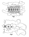
- Fig. 1 illustrates an apparatus 10 implanted into an adjacent pair of lumbar vertebrae 12 and 14 in a vertebral column (not shown). It should be understood that the apparatus 10 could be implanted into any adjacent pair of vertebrae.
- the vertebrae 12 has a side surface 16 and a lower surface (or end plate) 17 ( Fig. 2 ).
- the vertebrae 14 has a side surface 18 and an upper surface (or end plate) 19.
- the apparatus 10 comprises an interbody stabilizer 20 made from a biocompatible material, such as titanium or stainless steel. It is contemplated that the biocompatible material used to make the interbody stabilizer 20 could also be biodegradable.
- the interbody stabilizer 20 is centered about a longitudinal axis 22 ( Fig. 3 ).
- the interbody stabilizer 20 includes a platform 24 having a generally cylindrical outer surface 26 extending between oppositely disposed first and second ends 28 and 30.
- the second end 30 of the platform 24 includes an end surface 38 that extends transverse to the side surfaces 16 and 18 of the adjacent vertebrae 12 and 14, respectively.
- the end surface 38 of the platform 24 has a shape that is complimentary to the side surfaces 16 and 18 of the vertebrae 12 and 14, respectively.
- the platform 24 of the interbody stabilizer 20 further includes an axial passage 40 that extends from the first end 28 to the end surface 38.
- the passage 40 has a hexagonal configuration for receiving a rotatable driver (not shown).
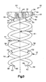
- First and second helical spikes 50 and 52 project from the end surface 38 of the platform 24.
- the helical spikes 50 and 52 resemble a pair of intertwined corkscrews.
- the first and second helical spikes 50 and 52 extend around the axis 22.
- the spikes 50 and 52 extend in a helical pattern about the axis 22 at the same, constant radius R1. It is contemplated, however, that the first and second helical spikes 50 and 52 could extend about the axis 22 at different radiuses. Further, it is contemplated that the radius of one or both of the first and second helical spikes 50 and 52 could increase or decrease as the helical spikes extend away from the platform 24.
- the platform 24 and the helical spikes 50 and 52 are less than 20mm in overall diameter. It should be understood that the interbody stabilizer 20 could have an overall diameter that is greater than 20mm for certain applications, and that the interbody stabilizer could also be implanted in an open surgical procedure. However, for structural stability reasons, the overall diameter of the helical spikes 50 and 52 should remain less than or equal to the diameter of the platform 24.
- first and second helical spikes 50 and 52 have the same axial length, and also have the same circular cross-sectional shape. It is contemplated, however, that the first and second helical spikes 50 and 52 could have different axial lengths. Further, it is contemplated that the helical spikes 50 and 52 could have a different cross-sectional shape, such as an oval shape. It also contemplated that the first and second helical spikes 50 and 52 could have different cross-sectional shapes and/or areas (i.e., one spike being thicker than the other spike).
- the helical spikes 50 and 52 should have the same pitch, and that the pitch of the helical spikes would be selected based on the specific surgical application and quality of the bone in which the interbody stabilizer 20 is to be implanted.
- Each of the first and second helical spikes 50 and 52 can be divided into three portions: a connecting portion 54, an intermediate portion 56, and a tip portion 58.
- the connecting portion 54 of each of the helical spikes 50 and 52 is located at a proximal end 60 that adjoins the end surface 38 of the platform 24.
- the connecting portion 54 may include barbs (not shown) for resisting pull-out of the helical spikes 50 and 52 from the vertebrae 12 and 14.
- the connecting portion 54 of each of the helical spikes 50 and 52 is fixedly attached to the platform 24 by inserting, in a tangential direction, the proximal ends 60 of the helical spikes into openings (not shown) in the end surface 38 and welding the connecting portions 54 to the platform.
- the inserted proximal ends 60 of the helical spikes 50 and 52 help to reduce tensile bending stresses on the helical spikes under a tensile load.
- the helical spikes 50 and 52 may be formed integrally with the platform 24, such as by casting the interbody stabilizer 20. If the interbody stabilizer 20 is cast, it is contemplated that a fillet (not shown) may be added at the junction of the helical spikes 50 and 52 and the platform 24 to strengthen the junction and minimize stress concentrations at the connecting portions 54. The fillet at the junction of the helical spikes 50 and 52 and the platform 24 also helps to reduce bending stresses in the connecting portions 54 of the helical spikes under a tensile load.
- the connecting portions 54 at the proximal ends 60 of the first and second helical spikes 50 and 52 are spaced 180° apart about the axis 22 to balance the interbody stabilizer 20 and evenly distribute loads on the helical spikes.
- the connecting portion 54 of each of the helical spikes 50 and 52 has a first cross-sectional diameter D1 ( Fig. 3 ).
- the tip portion 58 of each of the helical spikes 50 and 52 is located at a distal end 62 of the helical spikes.
- the intermediate portion 56 of each of the helical spikes 50 and 52 extends between the tip portion 58 and the connecting portion 54.
- the intermediate portion 56 and the tip portion 58 of each of the helical spikes 50 and 52 has a second cross-sectional diameter D2 that is less than or equal to the first cross-sectional diameter D1 of the connecting portions 54. If the second cross-sectional diameter D2 is less than the first cross-section diameter D1, the increased thickness of the connecting portions 54 of the helical spikes 50 and 52 will help to provide the interbody stabilizer 20 with increased tensile strength at the junction of the helical spikes and the platform 24.
- each of the helical spikes 50 and 52 is self-penetrating and provides the helical spikes with the ability to penetrate into a respective one of the vertebrae 12 and 14 as the platform 24 of the interbody stabilizer 20 is rotated in a clockwise direction.
- the tip portions 58 illustrated in Figs. 1-4 have an elongated conical shape with a sharp pointed tip 68.
- Fig. 5 illustrates an alternative, self-tapping configuration for the tip portions 58 which includes a planar surface 66 for driving into the vertebrae 12 and 14, in the same manner that a wood chisel turned upside-down drives into wood, as the platform 24 is rotated. It is contemplated that the tip portions 58 could also have a pyramid shape, similar to the tip of a nail.
- Figs. 1 and 2 illustrate the interbody stabilizer 20 implanted in the adjacent lumbar vertebrae 12 and 14 to stabilize the vertebrae.
- disk material that normally separates the vertebrae 12 and 14 is removed by the surgeon. Removal of the disk material leaves an interbody space 60 ( Fig. 2 ) between the vertebrae 12 and 14.
- a tool (not shown) is then used to punch a hole (not shown) in the cortical bone (not shown) of each of the vertebrae 12 and 14.
- the hole in the vertebrae 12 may be punched in either the side surface 16 or the lower surface 17.
- the hole in the vertebrae 14 may be punched in either the side surface 18 or the upper surface 19.
- the holes in the vertebrae 12 and 14 are punched in locations that correspond to the spacing of the tip portions 58 of the helical spikes 50 and 52 of the interbody stabilizer 20.
- the holes in the vertebrae 12 and 14 are intended to make the initial rotation of the stabilizer 20 easier. It should be noted that one or both of the configurations of the tip portions 58 illustrated in Figs. 1-5 may be able to punch through the cortical bone upon rotation of the interbody stabilizer 20, thus eliminating the need for the aforementioned tool to punch holes in the cortical bone.
- the tip portions 58 of the interbody stabilizer 20 are placed in the holes in the vertebrae 12 and 14 and a rotatable driver (not shown) is inserted into the passage 40 in the platform 24. The driver is then rotated, causing the interbody stabilizer 20 to rotate as well. It is contemplated that a cylindrical sleeve (not shown) may be placed around the intermediate portions 56 and the connecting portions 54 of the helical spikes 50 and 52 to prevent the helical spikes from deforming radially outward during the initial rotation of the interbody stabilizer 20.
- Rotation of the interbody stabilizer 20 screws the helical spikes 50 and 52 into the vertebrae 12 and 14, respectively.
- the tangentially-oriented connection between the connection portions 54 of the helical spikes 50 and 52 and the platform 24 minimizes bending loads on the connecting portions during rotation of the interbody stabilizer 20. Further, the tangentially-oriented connection ensures that the force vector resulting from axial force torque and applied by the driver 70 to the platform 24 is transmitted along the helical centerline (not shown) of each of the helical spikes 50 and 52.
- the tip portion 58 of the first helical spike 50 penetrates the cancellous bone in the vertebrae 12 and cuts a first helical segment 82 of a first tunnel 80 ( Fig. 1 ) in the vertebrae 12.
- the tip portion 58 of the second helical spike 52 penetrates the cancellous bone of the vertebrae 14 and cuts a first helical segment 102 of a second tunnel 100 in the vertebrae 14.
- the tip portions 58 of the helical spikes 50 and 52 penetrate back out of the vertebrae 12 and 14, respectively and into the interbody space 60. More specifically, the tip portion 58 of the first helical spike 50 projects through the lower surface 17 of the vertebrae 12 and into the interbody space 60. Simultaneously, the tip portion 58 of the second helical spike 52 projects through the upper surface 19 of the vertebrae 14 and into the interbody space 60.
- the tip portions 58 of the helical spikes 50 and 52 move through the interbody space 60 and engage the vertebrae 14 and 12, respectively.
- the tip portion 58 of the first helical spike 50 penetrates into the upper surface 19 of the vertebrae 14, while the tip portion 58 of the second helical spike 52 projects through the lower surface 17 of the vertebrae 12.
- Continued rotation of the interbody stabilizer 20 causes the tip portion 58 of the first helical spike 50 to cut a second helical segment 84 of the first tunnel 80 in the vertebrae 14.
- the continued rotation causes the tip portion 58 of the second helical spike 52 to cut a second helical segment 104 of the second tunnel 100 in the vertebrae 12.
- the tip portions 58 of the helical spikes 50 and 52 penetrate back out of the vertebrae 14 and 12, respectively, and into the interbody space 60. More specifically, the tip portion 58 of the first helical spike 50 projects through the upper surface 19 of the vertebrae 14 and the tip portion 58 of the second helical spike 52 projects through the lower surface 17 of the vertebrae 12.
- the tip portions 58 of the helical spikes 50 and 52 move through the interbody space 60 and re-engage the vertebrae 12 and 14, respectively.
- the tip portion 58 of the first helical spike 50 penetrates the lower surface 17 of the vertebrae 12 and cuts a third helical segment 86 of the first tunnel 80 in the vertebrae 12.
- the tip portion 58 of the second helical spike 52 penetrates the lower surface 19 of the vertebrae 14 and cuts a third helical segment 106 of the second tunnel 100 in the vertebrae 14.
- the tip portions 58 of the helical spikes 50 and 52 again penetrate back out of the vertebrae 12 and 14, respectively and into the interbody space 60.
- the tip portion 58 of the first helical spike 50 projects through the lower surface 17 of the vertebrae 12, while the tip portion 58 of the second helical spike 52 projects through the upper surface 19 of the vertebrae 14.
- the interbody stabilizer 20 is then rotated so that the tip portions 58 of the helical spikes 50 and 52 move through the interbody space 60 and re-engage the vertebrae 14 and 12, respectively.
- the tip portion 58 of the first helical spike 50 again penetrates into the upper surface 19 of the vertebrae 14, causing the tip portion 58 of the first helical spike 50 to cut a fourth helical segment 88 of the first tunnel 80 in the vertebrae 14.
- the tip portion 58 of the second helical spike 52 again penetrates through the lower surface 17 of the vertebrae 12, causing the tip portion 58 of the second helical spike 52 to cut a fourth helical segment 108 of the second tunnel 100 in the vertebrae 12.
- This pattern of screwing the helical spikes 50 and 52 of the interbody stabilizer 20 into and out of each of the vertebrae 12 and 14 in an alternating manner continues with each revolution of the platform 24 by the driver.
- the continued rotation of the platform 24 embeds the helical spikes 50 and 52 of the interbody stabilizer 20 into the vertebrae 12 and 14 and attaches the interbody stabilizer to each of the vertebrae.
- the connection between the interbody stabilizer and each of the vertebrae 12 and 14 gets stronger.
- the attachment of the interbody stabilizer 20 to each of the vertebrae 12 and 14 thus fastens, or pins, the vertebrae together, yet spaced apart.
- Rotation of the platform 24 is terminated when the end surface 38 of the platform seats against one or both of the side surfaces 16 and 18 of the vertebrae 12 and 14, respectively.
- bone graft material 130 (shown schematically in Figs. 1 and 2 ) for permanently fusing the vertebrae 12 and 14 is placed into the interbody space 60. More specifically, the bone graft material 130 is placed into a cavity 140 defined by the helical spikes 50 and 52, the lower surface 17 of the vertebrae 12, and the lower surface 19 of the vertebrae 14.
- the bone graft material 130 which may comprise bone chips and/or synthetic bone material, is placed into the cavity 140 through the axial passage 40 in the platform 24 of the interbody stabilizer 20. A sufficient amount of the bone graft material 130 is placed into the cavity 140 to fill not only the cavity, but also the entire interbody space 60.
- the interbody stabilizer 20 When implanted, the interbody stabilizer 20 is attached to both of the vertebrae 12 and 14 and securely fastens the vertebrae together. Because each of the helical spikes 50 and 52 penetrates into and subsequently out of each of the vertebrae 12 and 14, the helical spikes provide multiple fixation locations between the interbody stabilizer 20 and the vertebrae that pin the vertebrae together.
- the interbody stabilizer 20 is therefore able to resist relative movement of the vertebrae 12 and 14 toward or away from each other, and does not rely on surrounding ligaments to stabilize the vertebrae. More specifically, the interbody stabilizer 20 resists relative movement of the vertebrae 12 and 14, through bending or rotation, along any one of the three planes of motion (sagittal, coronal, or horizontal).
- the interbody stabilizer 20 is able to maintain proper intervertebral spacing and provide effective temporary stabilization of the adjacent vertebrae 12 and 14, despite substantial forces on the interbody stabilizer caused by human body movement and muscle memory, while the bone graft material 130 fuses the vertebrae together.
- the interbody stabilizer 20 has a simple one-piece construct and does not require substantial cutting of cortical bone (i.e., a reaming or tapping procedure) to prepare the vertebrae 12 and 14 to accept the interbody stabilizer.
- the interbody stabilizer 20 is not only a simplified construct, but also simplifies the steps required for implantation into adjacent vertebrae.
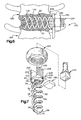
- Figs. 6 and 7 illustrate an apparatus 210 constructed in accordance with a second embodiment of the present invention.
- reference numbers that are the same as those used in the first embodiment of Figs. 1-4 designate parts that are the same as parts in the first embodiment.
- the apparatus 210 comprises an interbody stabilizer 220 having a platform 224.
- the platform 224 includes a generally rectangular slot 232 that extends axially from a first end 228 toward a second end 230 of the platform. Adjacent the first end 228, the platform 224 includes first and second segments of external threads 234 and 236 that are separated by the slot 232.
- the slot 232 and the threads 234 and 236 provide structure for connecting spinal fixation instrumentation to the platform 24.
- the first and second helical spikes 50 and 52 project from the end surface 38 at the second end 230 of the platform 224.
- Fig. 6 illustrates how the interbody stabilizer 220 may be used for segmental spinal fixation.
- Lumbar vertebrae L3 and L4, indicated by reference numbers 290 and 292, respectively, are shown in Fig. 6 .
- the interbody stabilizer 220 according to the second embodiment of the present invention is implanted in the interbody space between the vertebrae 290 and 292.
- the interbody stabilizer 220 is implanted into the vertebrae 290 and 292 in much the same manner as described above regarding the first embodiment.
- a rotatable driver 270 ( Fig. 7 ) fits into the slot 232 in the interbody stabilizer 220 and is used to rotate the interbody stabilizer.
- spinal fixation instrumentation such as a beam 280 which has been bent into a desired shape by the surgeon, is placed into the slot 232 in the interbody stabilizer.
- a nut 282 is then screwed onto the threads 234 and 236 on the platform 24 and tightened to secure the beam 280 to the interbody stabilizer 220.
- the interbody stabilizer 220 fastens the vertebrae 290 and 292 together and stabilizes the vertebrae until the bone graft material 130 placed in the cavity 140 defined inside each of the interbody stabilizers fuses the vertebrae.
- the beam 280 helps to further support the vertebrae 290 and 292 until the vertebrae fuse together.
- Fig. 8 illustrates an apparatus 310 constructed in accordance with a third embodiment of the present invention.
- reference numbers that are the same as those used in the first embodiment of Figs. 1-4 designate parts that are the same as parts in the first embodiment.
- the interbody stabilizer 20 is implanted into two cervical vertebrae 312 and 314 in the same manner as described above regarding the first embodiment.
- the end surface 38 of the interbody stabilizer 20 seats against anterior surfaces 316 and 318 of the vertebrae 312 and 314, respectively.
- the interbody stabilizer 20 fastens the vertebrae 312 and 314 and stabilizes the vertebrae until the bone graft material 130 placed in the cavity 140 in the interbody stabilizer fuses the vertebrae.
- Figs. 9 and 10 illustrate an apparatus 410 constructed in accordance with a fourth embodiment of the present invention.
- reference numbers that are the same as those used in the first embodiment of Figs. 1-4 designate parts that are the same as parts in the first embodiment.
- the apparatus 410 comprises an interbody stabilizer 420 having three helical spikes 430, 431, and 432 projecting tangentially from the end surface 38 of the platform 24.
- the spikes 430-432 are centered about the axis 22.
- the connecting portions 54 at the proximal ends 60 of the helical spikes 430-432 are spaced 120° apart about the axis 22, which balances the interbody stabilizer 420 and evenly distributes loads on the helical spikes.
- the cross-sectional diameter of the connection portions 54 of the helical spikes 430-432 is greater than or equal to the cross-sectional diameter of the intermediate portions 56 and the tip portions 58 of the helical spikes.
- Each of the three helical spikes 430-432 extend in a helical pattern about the axis 22 at the same, constant radius R1. It is contemplated, however, that one or more of the helical spikes 430-432 could extend about the axis 22 at different radiuses. Further, it is contemplated that the radius of one or more helical spikes 430-432 could increase or decrease as the helical spikes extend away from the platform 24.
- the three helical spikes 430-432 have the same axial length and also have the same circular cross-sectional shape. It is contemplated, however, that one or more of the helical spikes 430-432 could have different axial lengths. Further, it is contemplated that one or more of the helical spikes 430-432 could have a different cross-sectional shape, such as an oval shape. It also contemplated that the one or more of the helical spikes 430-432 could have different cross-sectional shapes and/or areas (i.e., one spike being thicker or thinner than the other two spikes).
- the helical spikes 430-432 should have the same pitch, and that the pitch of the helical spikes would be selected based on the specific surgical application and quality of the bone in which the interbody stabilizer 20 is to be implanted.
- each of the helical spikes 430-432 illustrated in Fig. 8 has an elongated conical shape for penetrating into a vertebrae as the platform 24 of the interbody stabilizer 420 is rotated in the clockwise direction. It should be understood that the tip portions 58 of the helical spikes 430-432 of the interbody stabilizer 420 could alternatively be configured like the tip portions illustrated in Fig. 5 .
- the interbody stabilizer 420 according to the fourth embodiment of Figs. 9 and 10 is implanted into an adjacent pair of vertebrae in the same manner as the interbody stabilizer 20 according to the first embodiment. Further, the interbody stabilizer 420 according to the fourth embodiment may also be used to mount spinal fixation instrumentation as shown in the second embodiment of Figs. 6 and 7 . When implanted, the interbody stabilizer 420 is attached to both of the adjacent vertebrae and fastens the vertebrae together. Further, the interbody stabilizer 420 maintains proper intervertebral spacing and provides effective temporary stabilization of the adjacent vertebrae while the bone graft material placed in the cavity in the interbody stabilizer fuses the vertebrae together.
- the interbody stabilizer 420 is a simple one-piece construct does not require substantial cutting of cortical bone (i.e., a reaming or tapping procedure) to prepare the adjacent vertebrae to accept the interbody stabilizer.
- interbody stabilizers can be used not only to stabilize a degenerative disc, but can also be used to correct spinal deformity such as scoliosis, kyphosis, lordosis, and spondylosisthesis.
Abstract
Claims (10)
- Dispositif (10, 210, 310, 410) destiné à être implanté dans une paire adjacente de corps vertébraux (12, 14, 290, 292, 312, 314) comportant des première et deuxième surfaces (16, 17, 18, 19, 316, 318), respectivement, qui se font face, ledit dispositif (10, 210, 310, 410), lorsqu'il est implanté, étant fixé à chacun des corps vertébraux (12, 14, 290, 292, 312, 314) et stabilisant les corps vertébraux (12, 14, 290, 292, 312, 314) tandis que les corps vertébraux (12, 14, 290, 292, 312, 314) fusionnent l'un avec l'autre, ledit dispositif (10, 210, 310, 410) comprenant :une plateforme (24, 224) comportant une troisième surface (38) s'étendant transversalement aux première et deuxième surfaces (16, 17, 18, 19, 316, 318) et transversalement à un axe longitudinal (22) dudit dispositif (10, 210, 310, 410) ; etau moins deux pointes hélicoïdales (50, 52, 430, 431, 432) en forme de tire-bouchons entrelacés destinées à être enfoncées dans chacun de la paire adjacente de corps vertébraux (12, 14, 290, 292, 312, 314) lors de la rotation de ladite plateforme (24, 224) pour fixer lesdites au moins deux pointes hélicoïdales (50, 52, 430, 431, 432) à chacun des corps vertébraux (12, 14, 290, 292, 312, 314) et ainsi fixer les corps vertébraux (12, 14, 290, 292, 312, 314) l'un à l'autre, lesdites au moins deux pointes hélicoïdales (50, 52, 430, 431, 432) faisant saillie de ladite troisième surface (38) de ladite plateforme (24, 224) et s'étendant autour dudit axe longitudinal (22), chacune desdites au moins deux pointes hélicoïdales (50, 52, 430, 431, 432) ayant une partie de liaison (54) à une extrémité proximale (60) reliée à ladite plateforme (24, 224), lesdites au moins deux pointes hélicoïdales (50, 52, 430, 431, 432) comportant en outre une partie d'extrémité (58) à une extrémité distale (62) destinée à pénétrer dans les première et deuxième surfaces (16, 17, 18, 19, 316, 318) et destinée à être vissée dans la paire adjacente de corps vertébraux (12, 14, 290, 292, 312, 314) alors que ladite plateforme (24, 224) est tournée ;lesdites au moins deux pointes hélicoïdales (50, 52, 430, 431, 432) définissant au moins partiellement une cavité interne (40) pour recevoir un matériau (130) qui favorise la fusion des corps vertébraux (12, 14, 290, 292, 312, 314).
- Dispositif (10, 210, 310, 410) selon la revendication 1, dans lequel ladite plateforme (24, 224) comprend un passage (40) s'étendant axialement à travers lequel le matériau (130) est placé dans ladite cavité interne (40) à la suite de l'implantation dudit dispositif (10, 210, 310, 410) dans les corps vertébraux (12, 14, 290, 292, 312, 314).
- Dispositif (10, 210, 310, 410) selon la revendication 1, dans lequel lesdites au moins deux pointes hélicoïdales (50, 52, 430, 431, 432) comprennent une paire de pointes hélicoïdales (50, 52, 430, 431, 432), lesdites extrémités proximales (60) de ladite paire de pointes hélicoïdales (50, 52, 430, 431, 432) étant espacées de 180°.
- Dispositif (10, 210, 310, 410) selon la revendication 1, dans lequel lesdites au moins deux pointes hélicoïdales (50, 52, 430, 431, 432) comprennent trois pointes hélicoïdales (50, 52, 430, 431, 432), lesdites extrémités proximales (60) desdites trois pointes hélicoïdales (50, 52, 430, 431, 432) étant espacées de 120°.
- Dispositif (10, 210, 310, 410) selon la revendication 1, dans lequel ladite plateforme (24, 224) comprend une structure (232, 234, 236) pour le raccordement d'une instrumentation de fixation spinale (280).
- Dispositif (10, 210, 310, 410) selon la revendication 1, dans lequel chacune desdites au moins deux pointes hélicoïdales (50, 52, 430, 431, 432) comporte une partie intermédiaire (56) s'étendant entre ladite partie de liaison (54) et ladite partie d'extrémité (58).
- Dispositif (10, 210, 310, 410) selon la revendication 6, dans lequel ladite partie intermédiaire (56) de chacune desdites au moins deux pointes hélicoïdales (50, 52, 430, 431, 432) a un premier diamètre de section (D2) et ladite partie de liaison (54) de chacune desdites au moins deux pointes hélicoïdales (50, 52, 430, 431, 432) a un deuxième diamètre de section (D1) qui est plus grand que ledit premier diamètre de section (D2).
- Dispositif (10, 210, 310, 410) selon la revendication 6, dans lequel ladite partie intermédiaire (56) de chacune desdites au moins deux pointes hélicoïdales (50, 52, 430, 431, 432) a un premier diamètre de section (D2) et ladite partie de liaison (54) de chacune desdites au moins deux pointes hélicoïdales a un deuxième diamètre de section (D1) qui est égal audit premier diamètre de section (D2).
- Dispositif (10, 210, 310, 410) selon la revendication 1, dans lequel ladite plateforme (24, 224) et lesdites au moins deux pointes hélicoïdales (50, 52, 430, 431, 432) sont réalisées en un matériau biocompatible.
- Dispositif (10, 210, 310, 410) selon la revendication 1, dans lequel ladite partie d'extrémité (58) de chacune desdites au moins deux pointes hélicoïdales (50, 52, 430, 431, 432) a une extrémité terminale auto-pénétrante (66, 68) pour pénétrer dans l'os (12, 14, 290, 292, 312, 314) alors que ladite plateforme (24, 224) est tournée.
Applications Claiming Priority (5)
| Application Number | Priority Date | Filing Date | Title |
|---|---|---|---|
| US708292 | 1991-05-31 | ||
| US23826500P | 2000-10-05 | 2000-10-05 | |
| US238265P | 2000-10-05 | ||
| US09/708,292 US6468309B1 (en) | 2000-10-05 | 2000-11-08 | Method and apparatus for stabilizing adjacent bones |
| PCT/US2001/030405 WO2002028323A1 (fr) | 2000-10-05 | 2001-09-28 | Procede et appareil permettant de stabiliser des os adjacents |
Publications (3)
| Publication Number | Publication Date |
|---|---|
| EP1322263A1 EP1322263A1 (fr) | 2003-07-02 |
| EP1322263A4 EP1322263A4 (fr) | 2007-11-21 |
| EP1322263B1 true EP1322263B1 (fr) | 2009-09-02 |
Family
ID=26931491
Family Applications (1)
| Application Number | Title | Priority Date | Filing Date |
|---|---|---|---|
| EP01977247A Expired - Lifetime EP1322263B1 (fr) | 2000-10-05 | 2001-09-28 | Appareil permettant de stabiliser des os adjacents |
Country Status (7)
| Country | Link |
|---|---|
| US (2) | US6468309B1 (fr) |
| EP (1) | EP1322263B1 (fr) |
| JP (1) | JP3929893B2 (fr) |
| AU (2) | AU2001296380B2 (fr) |
| CA (1) | CA2424261C (fr) |
| DE (1) | DE60139790D1 (fr) |
| WO (1) | WO2002028323A1 (fr) |
Families Citing this family (135)
| Publication number | Priority date | Publication date | Assignee | Title |
|---|---|---|---|---|
| US5662683A (en) * | 1995-08-22 | 1997-09-02 | Ortho Helix Limited | Open helical organic tissue anchor and method of facilitating healing |
| US20050143734A1 (en) * | 1996-11-12 | 2005-06-30 | Cachia Victor V. | Bone fixation system with radially extendable anchor |
| US6648890B2 (en) | 1996-11-12 | 2003-11-18 | Triage Medical, Inc. | Bone fixation system with radially extendable anchor |
| US7491232B2 (en) * | 1998-09-18 | 2009-02-17 | Aptus Endosystems, Inc. | Catheter-based fastener implantation apparatus and methods with implantation force resolution |
| US7678151B2 (en) | 2000-05-01 | 2010-03-16 | Ek Steven W | System and method for joint resurface repair |
| US7896883B2 (en) | 2000-05-01 | 2011-03-01 | Arthrosurface, Inc. | Bone resurfacing system and method |
| US7713305B2 (en) | 2000-05-01 | 2010-05-11 | Arthrosurface, Inc. | Articular surface implant |
| US7163541B2 (en) | 2002-12-03 | 2007-01-16 | Arthrosurface Incorporated | Tibial resurfacing system |
| US6520964B2 (en) | 2000-05-01 | 2003-02-18 | Std Manufacturing, Inc. | System and method for joint resurface repair |
| US6610067B2 (en) | 2000-05-01 | 2003-08-26 | Arthrosurface, Incorporated | System and method for joint resurface repair |
| US8177841B2 (en) | 2000-05-01 | 2012-05-15 | Arthrosurface Inc. | System and method for joint resurface repair |
| US6953462B2 (en) | 2000-10-05 | 2005-10-11 | The Cleveland Clinic Foundation | Apparatus for implantation into bone |
| US20020169507A1 (en) * | 2000-12-14 | 2002-11-14 | David Malone | Interbody spine fusion cage |
| US6511481B2 (en) | 2001-03-30 | 2003-01-28 | Triage Medical, Inc. | Method and apparatus for fixation of proximal femoral fractures |
| US6887243B2 (en) | 2001-03-30 | 2005-05-03 | Triage Medical, Inc. | Method and apparatus for bone fixation with secondary compression |
| CA2702143C (fr) | 2001-06-05 | 2014-02-18 | Mikro Systems, Inc. | Procedes de fabrication de dispositifs tridimensionnels, et dispositifs crees par ces procedes |
| US7785098B1 (en) | 2001-06-05 | 2010-08-31 | Mikro Systems, Inc. | Systems for large area micro mechanical systems |
| RU2194274C1 (ru) * | 2001-09-18 | 2002-12-10 | ЗАО "Нефтегазкомплектсервис" | Способ внутритрубного ультразвукового контроля |
| WO2003099148A2 (fr) * | 2002-05-21 | 2003-12-04 | Sdgi Holdings, Inc. | Cable de reduction et ancrage osseux |
| US6793678B2 (en) | 2002-06-27 | 2004-09-21 | Depuy Acromed, Inc. | Prosthetic intervertebral motion disc having dampening |
| WO2004008949A2 (fr) | 2002-07-19 | 2004-01-29 | Triage Medical, Inc. | Procede et appareil de fixation vertebrale |
| US20040078084A1 (en) * | 2002-10-22 | 2004-04-22 | Ricardo Albertorio | Prosthetic implant and method of use |
| US7901408B2 (en) | 2002-12-03 | 2011-03-08 | Arthrosurface, Inc. | System and method for retrograde procedure |
| WO2004073563A2 (fr) | 2003-02-14 | 2004-09-02 | Depuy Spine, Inc. | Dispositif et procede de fusion intervertebrale forme in-situ |
| US8388624B2 (en) | 2003-02-24 | 2013-03-05 | Arthrosurface Incorporated | Trochlear resurfacing system and method |
| US20040225361A1 (en) * | 2003-03-14 | 2004-11-11 | Glenn Bradley J. | Intervertebral disk nuclear augmentation system |
| AU2003209911A1 (en) * | 2003-03-24 | 2004-10-18 | Synthes Gmbh | Vertebral disc or intervertebral disc prosthesis |
| US20040199256A1 (en) * | 2003-04-04 | 2004-10-07 | Chao-Jan Wang | Support device for supporting between spinal vertebrae |
| US20050002753A1 (en) * | 2003-07-03 | 2005-01-06 | Haas James R. | Rotary fastener, fastenable material, fastener system, and storage system |
| EP1845890A4 (fr) | 2003-11-20 | 2010-06-09 | Arthrosurface Inc | Systeme et procede pour acces retrograde |
| US7951163B2 (en) | 2003-11-20 | 2011-05-31 | Arthrosurface, Inc. | Retrograde excision system and apparatus |
| AU2004293042A1 (en) | 2003-11-20 | 2005-06-09 | Arthrosurface, Inc. | Retrograde delivery of resurfacing devices |
| US8230794B1 (en) | 2004-02-05 | 2012-07-31 | James Haas | Holding system and method for a workbench |
| US8142128B1 (en) * | 2004-02-05 | 2012-03-27 | James Haas | Anchor and method for anchoring |
| US8047890B1 (en) | 2004-02-05 | 2011-11-01 | James Haas | Toy construction set and method |
| US8523904B2 (en) | 2004-03-09 | 2013-09-03 | The Board Of Trustees Of The Leland Stanford Junior University | Methods and systems for constraint of spinous processes with attachment |
| US7458981B2 (en) | 2004-03-09 | 2008-12-02 | The Board Of Trustees Of The Leland Stanford Junior University | Spinal implant and method for restricting spinal flexion |
| WO2005092018A2 (fr) * | 2004-03-23 | 2005-10-06 | Sdgi Holdings, Inc. | Procede et dispositif destines a la fixation de la colonne vertebrale et visant a corriger les deformations de la colonne vertebrale |
| JP2008504107A (ja) | 2004-06-28 | 2008-02-14 | アースロサーフィス・インコーポレーテッド | 関節面交換用システム |
| US7637918B2 (en) * | 2004-08-16 | 2009-12-29 | Zimmer Spine, Inc. | Helical suturing device |
| US7799081B2 (en) | 2004-09-14 | 2010-09-21 | Aeolin, Llc | System and method for spinal fusion |
| US7828853B2 (en) | 2004-11-22 | 2010-11-09 | Arthrosurface, Inc. | Articular surface implant and delivery system |
| DE102004063396B4 (de) * | 2004-12-23 | 2006-11-02 | Michael Zielsdorf | Marknagel |
| US7666226B2 (en) | 2005-08-16 | 2010-02-23 | Benvenue Medical, Inc. | Spinal tissue distraction devices |
| US8366773B2 (en) | 2005-08-16 | 2013-02-05 | Benvenue Medical, Inc. | Apparatus and method for treating bone |
| WO2008103781A2 (fr) | 2007-02-21 | 2008-08-28 | Benvenue Medical, Inc. | Dispositif pour traiter le rachis |
| WO2007130699A2 (fr) * | 2006-01-13 | 2007-11-15 | Clifford Tribus | dispositif de reduction et de stabilisation spinale |
| US7740659B2 (en) * | 2006-06-29 | 2010-06-22 | Depuy Spine, Inc. | Insert for nucleus implant |
| US20110213375A1 (en) | 2006-07-17 | 2011-09-01 | Arthrosurface, Inc. | Tibial Resurfacing System and Method |
| US8162982B2 (en) | 2006-10-19 | 2012-04-24 | Simpirica Spine, Inc. | Methods and systems for constraint of multiple spine segments |
| US8029541B2 (en) | 2006-10-19 | 2011-10-04 | Simpirica Spine, Inc. | Methods and systems for laterally stabilized constraint of spinous processes |
| WO2008051801A2 (fr) | 2006-10-19 | 2008-05-02 | Simpirica Spine, Inc. | Structures et méthodes de contrainte de processus spinaux à connecteur unique |
| US20080262549A1 (en) * | 2006-10-19 | 2008-10-23 | Simpirica Spine, Inc. | Methods and systems for deploying spinous process constraints |
| US8187307B2 (en) | 2006-10-19 | 2012-05-29 | Simpirica Spine, Inc. | Structures and methods for constraining spinal processes with single connector |
| WO2008070863A2 (fr) | 2006-12-07 | 2008-06-12 | Interventional Spine, Inc. | Implant intervertébral |
| US9358029B2 (en) | 2006-12-11 | 2016-06-07 | Arthrosurface Incorporated | Retrograde resection apparatus and method |
| US20080154374A1 (en) * | 2006-12-20 | 2008-06-26 | Robert David Labrom | Joint implant and a surgical method associated therewith |
| US20080177389A1 (en) * | 2006-12-21 | 2008-07-24 | Rob Gene Parrish | Intervertebral disc spacer |
| US8034081B2 (en) | 2007-02-06 | 2011-10-11 | CollabComl, LLC | Interspinous dynamic stabilization implant and method of implanting |
| ES2757819T3 (es) | 2007-02-21 | 2020-04-30 | Benvenue Medical Inc | Dispositivos para tratar la columna vertebral |
| US7998176B2 (en) | 2007-06-08 | 2011-08-16 | Interventional Spine, Inc. | Method and apparatus for spinal stabilization |
| US20110172708A1 (en) * | 2007-06-22 | 2011-07-14 | Simpirica Spine, Inc. | Methods and systems for increasing the bending stiffness of a spinal segment with elongation limit |
| EP2182864B1 (fr) | 2007-06-22 | 2016-06-08 | Empirical Spine, Inc. | Dispositifs pour restreindre de façon contrôlée la flexion de segments rachidiens |
| US20100036424A1 (en) | 2007-06-22 | 2010-02-11 | Simpirica Spine, Inc. | Methods and systems for increasing the bending stiffness and constraining the spreading of a spinal segment |
| US8900307B2 (en) | 2007-06-26 | 2014-12-02 | DePuy Synthes Products, LLC | Highly lordosed fusion cage |
| JP5441922B2 (ja) | 2008-01-17 | 2014-03-12 | ジンテス ゲゼルシャフト ミット ベシュレンクテル ハフツング | 膨張可能な椎間インプラント及び関連するその製造方法 |
| EP2262449B1 (fr) | 2008-04-05 | 2020-03-11 | Synthes GmbH | Implant intervertébral extensible |
| WO2009149407A1 (fr) | 2008-06-06 | 2009-12-10 | Simpirica Spine, Inc. | Procédés et appareil de blocage d'une sangle |
| WO2009149399A1 (fr) | 2008-06-06 | 2009-12-10 | Simpirica Spine, Inc. | Méthodes et appareil de mise en place d'éléments de contrainte de l'apophyse épineuse |
| WO2009149414A1 (fr) | 2008-06-06 | 2009-12-10 | Simpirica Spine, Inc. | Procédé et appareil pour verrouillage d'un ruban |
| CN103327557B (zh) | 2008-06-18 | 2017-03-01 | 爱默生过程管理电力和水力解决方案有限公司 | 用于通过区别网络进行无线过程通信的系统和方法 |
| CA2735001A1 (fr) * | 2008-09-02 | 2010-03-11 | Synthes Usa, Llc | Ancrage en spirale d'implant de fusion |
| ES2523801T3 (es) | 2008-09-03 | 2014-12-01 | Simpirica Spine, Inc. | Aparato para acoplar una prótesis a un segmento de columna vertebral |
| WO2010088621A1 (fr) | 2009-02-02 | 2010-08-05 | Simpirica Spine, Inc. | Ancrage par attache au sacrum et ses procédés d'utilisation |
| JP5681122B2 (ja) | 2009-03-10 | 2015-03-04 | シンピライカ スパイン, インコーポレイテッド | 外科用テザー装置および使用方法 |
| US8529606B2 (en) | 2009-03-10 | 2013-09-10 | Simpirica Spine, Inc. | Surgical tether apparatus and methods of use |
| US8562653B2 (en) | 2009-03-10 | 2013-10-22 | Simpirica Spine, Inc. | Surgical tether apparatus and methods of use |
| US8535327B2 (en) | 2009-03-17 | 2013-09-17 | Benvenue Medical, Inc. | Delivery apparatus for use with implantable medical devices |
| US9526620B2 (en) | 2009-03-30 | 2016-12-27 | DePuy Synthes Products, Inc. | Zero profile spinal fusion cage |
| WO2010114853A1 (fr) | 2009-03-30 | 2010-10-07 | Simpirica Spine, Inc. | Procédés et appareils destinés à améliorer la capacité de charge de cisaillement d'un segment spinal |
| US9408715B2 (en) * | 2009-04-15 | 2016-08-09 | DePuy Synthes Products, Inc. | Arcuate fixation member |
| US8641766B2 (en) | 2009-04-15 | 2014-02-04 | DePuy Synthes Products, LLC | Arcuate fixation member |
| WO2010121250A1 (fr) | 2009-04-17 | 2010-10-21 | Arthrosurface Incorporated | Système et procédé de re-surfaçage de glénoïde |
| EP2429429B1 (fr) | 2009-04-17 | 2018-07-25 | Arthrosurface Incorporated | Système de re-surfaçage de glénoïde |
| WO2016154393A1 (fr) | 2009-04-17 | 2016-09-29 | Arthrosurface Incorporated | Système de réparation de glénoïde et ses méthodes d'utilisation |
| DK2253291T3 (en) * | 2009-05-19 | 2016-06-13 | Nat Univ Ireland Galway | The bone implants with a structure overfladeforankrende |
| US8459524B2 (en) | 2009-08-14 | 2013-06-11 | Covidien Lp | Tissue fastening system for a medical device |
| US9393129B2 (en) | 2009-12-10 | 2016-07-19 | DePuy Synthes Products, Inc. | Bellows-like expandable interbody fusion cage |
| US8845733B2 (en) | 2010-06-24 | 2014-09-30 | DePuy Synthes Products, LLC | Lateral spondylolisthesis reduction cage |
| US8979860B2 (en) | 2010-06-24 | 2015-03-17 | DePuy Synthes Products. LLC | Enhanced cage insertion device |
| TW201215379A (en) | 2010-06-29 | 2012-04-16 | Synthes Gmbh | Distractible intervertebral implant |
| WO2012048131A2 (fr) | 2010-10-06 | 2012-04-12 | Simpirica Spine, Inc. | Dispositif et accessoires pour limiter la flexion |
| US9402732B2 (en) | 2010-10-11 | 2016-08-02 | DePuy Synthes Products, Inc. | Expandable interspinous process spacer implant |
| US9066716B2 (en) | 2011-03-30 | 2015-06-30 | Arthrosurface Incorporated | Suture coil and suture sheath for tissue repair |
| US8814873B2 (en) | 2011-06-24 | 2014-08-26 | Benvenue Medical, Inc. | Devices and methods for treating bone tissue |
| EP2747679B1 (fr) * | 2011-08-23 | 2016-12-21 | Simcha Milo | Dispositif de création d'un accès temporaire puis d'une fermeture |
| WO2013096746A1 (fr) | 2011-12-22 | 2013-06-27 | Arthrosurface Incorporated | Système et procédé pour une fixation osseuse |
| US9554836B2 (en) * | 2012-06-29 | 2017-01-31 | The Cleveland Clinic Foundation | Intramedullary bone stent |
| DE112013003358T5 (de) | 2012-07-03 | 2015-03-19 | Arthrosurface, Inc. | System und Verfahren für Gelenkoberflächenersatz und -reparatur |
| EP2877127B1 (fr) | 2012-07-26 | 2019-08-21 | Synthes GmbH | Implant expansible |
| US8814912B2 (en) | 2012-07-27 | 2014-08-26 | Zimmer Spine, Inc. | Bone stabilization member with bone screw retention mechanism |
| US20140067069A1 (en) | 2012-08-30 | 2014-03-06 | Interventional Spine, Inc. | Artificial disc |
| US9522070B2 (en) | 2013-03-07 | 2016-12-20 | Interventional Spine, Inc. | Intervertebral implant |
| US10085783B2 (en) | 2013-03-14 | 2018-10-02 | Izi Medical Products, Llc | Devices and methods for treating bone tissue |
| US9119732B2 (en) | 2013-03-15 | 2015-09-01 | Orthocision, Inc. | Method and implant system for sacroiliac joint fixation and fusion |
| US9492200B2 (en) | 2013-04-16 | 2016-11-15 | Arthrosurface Incorporated | Suture system and method |
| US9522028B2 (en) | 2013-07-03 | 2016-12-20 | Interventional Spine, Inc. | Method and apparatus for sacroiliac joint fixation |
| US11607319B2 (en) | 2014-03-07 | 2023-03-21 | Arthrosurface Incorporated | System and method for repairing articular surfaces |
| US10624748B2 (en) | 2014-03-07 | 2020-04-21 | Arthrosurface Incorporated | System and method for repairing articular surfaces |
| US20150250472A1 (en) | 2014-03-07 | 2015-09-10 | Arthrosurface Incorporated | Delivery System for Articular Surface Implant |
| US9675465B2 (en) * | 2014-05-15 | 2017-06-13 | Globus Medical, Inc. | Standalone interbody implants |
| US11426290B2 (en) | 2015-03-06 | 2022-08-30 | DePuy Synthes Products, Inc. | Expandable intervertebral implant, system, kit and method |
| US10449051B2 (en) | 2015-04-29 | 2019-10-22 | Institute for Musculoskeletal Science and Education, Ltd. | Implant with curved bone contacting elements |
| EP3760166A1 (fr) | 2015-04-29 | 2021-01-06 | Institute For Musculoskeletal Science And Education, Ltd. | Implants spiralés, systèmes |
| US10092286B2 (en) | 2015-05-27 | 2018-10-09 | Covidien Lp | Suturing loading unit |
| US9913727B2 (en) | 2015-07-02 | 2018-03-13 | Medos International Sarl | Expandable implant |
| US10166116B2 (en) | 2015-12-02 | 2019-01-01 | Brian Patrick Janowski | Helical lock spacer, instruments and methods |
| WO2018002715A2 (fr) | 2016-06-28 | 2018-01-04 | Eit Emerging Implant Technologies Gmbh | Cages intervertébrales articulées à expansion et réglage angulaire |
| WO2018002711A2 (fr) | 2016-06-28 | 2018-01-04 | Eit Emerging Implant Technologies Gmbh | Cages intervertébrales à expansion et réglage angulaire |
| US10537436B2 (en) | 2016-11-01 | 2020-01-21 | DePuy Synthes Products, Inc. | Curved expandable cage |
| US10888433B2 (en) | 2016-12-14 | 2021-01-12 | DePuy Synthes Products, Inc. | Intervertebral implant inserter and related methods |
| US10512549B2 (en) * | 2017-03-13 | 2019-12-24 | Institute for Musculoskeletal Science and Education, Ltd. | Implant with structural members arranged around a ring |
| US10398563B2 (en) | 2017-05-08 | 2019-09-03 | Medos International Sarl | Expandable cage |
| US11344424B2 (en) | 2017-06-14 | 2022-05-31 | Medos International Sarl | Expandable intervertebral implant and related methods |
| US10940016B2 (en) | 2017-07-05 | 2021-03-09 | Medos International Sarl | Expandable intervertebral fusion cage |
| CA3108761A1 (fr) | 2017-08-04 | 2019-02-07 | Arthrosurface Incorporated | Implant de surface articulaire a composants multiples |
| US10744001B2 (en) | 2017-11-21 | 2020-08-18 | Institute for Musculoskeletal Science and Education, Ltd. | Implant with improved bone contact |
| US10940015B2 (en) | 2017-11-21 | 2021-03-09 | Institute for Musculoskeletal Science and Education, Ltd. | Implant with improved flow characteristics |
| USD921898S1 (en) | 2017-12-22 | 2021-06-08 | Orthocision Inc. | Helical implant |
| US11446156B2 (en) | 2018-10-25 | 2022-09-20 | Medos International Sarl | Expandable intervertebral implant, inserter instrument, and related methods |
| US11478358B2 (en) | 2019-03-12 | 2022-10-25 | Arthrosurface Incorporated | Humeral and glenoid articular surface implant systems and methods |
| US11426286B2 (en) | 2020-03-06 | 2022-08-30 | Eit Emerging Implant Technologies Gmbh | Expandable intervertebral implant |
| US11850160B2 (en) | 2021-03-26 | 2023-12-26 | Medos International Sarl | Expandable lordotic intervertebral fusion cage |
| US11752009B2 (en) | 2021-04-06 | 2023-09-12 | Medos International Sarl | Expandable intervertebral fusion cage |
| CN114305638A (zh) * | 2022-01-07 | 2022-04-12 | 洪琦 | 一种相邻椎体零切迹连体螺钉 |
Family Cites Families (37)
| Publication number | Priority date | Publication date | Assignee | Title |
|---|---|---|---|---|
| US2033039A (en) | 1935-05-22 | 1936-03-03 | Arthur A Limpert | Double point rotary pin |
| FR2299548A1 (fr) | 1975-01-30 | 1976-08-27 | Melin Raymond | Agrafe, ainsi que le dispositif pour sa mise en place |
| SU1071297A1 (ru) | 1982-09-17 | 1984-02-07 | Koptyukh Vladimir V | Устройство дл остеосинтеза |
| US4854311A (en) | 1986-01-09 | 1989-08-08 | Acro Med Corporation | Bone screw |
| US4762453A (en) | 1986-01-29 | 1988-08-09 | Textron, Inc. | Helical coil fastener |
| EP0703757B1 (fr) | 1988-06-13 | 2003-08-27 | Karlin Technology, Inc. | Appareil d'insertion d'implants spinaux |
| US6120502A (en) | 1988-06-13 | 2000-09-19 | Michelson; Gary Karlin | Apparatus and method for the delivery of electrical current for interbody spinal arthrodesis |
| US6123705A (en) | 1988-06-13 | 2000-09-26 | Sdgi Holdings, Inc. | Interbody spinal fusion implants |
| US4961740B1 (en) | 1988-10-17 | 1997-01-14 | Surgical Dynamics Inc | V-thread fusion cage and method of fusing a bone joint |
| CH681273A5 (fr) | 1988-12-16 | 1993-02-26 | Sulzer Ag | |
| US5458638A (en) * | 1989-07-06 | 1995-10-17 | Spine-Tech, Inc. | Non-threaded spinal implant |
| US5055104A (en) | 1989-11-06 | 1991-10-08 | Surgical Dynamics, Inc. | Surgically implanting threaded fusion cages between adjacent low-back vertebrae by an anterior approach |
| US5263953A (en) | 1991-12-31 | 1993-11-23 | Spine-Tech, Inc. | Apparatus and system for fusing bone joints |
| US5534031A (en) * | 1992-01-28 | 1996-07-09 | Asahi Kogaku Kogyo Kabushiki Kaisha | Prosthesis for spanning a space formed upon removal of an intervertebral disk |
| US5423817A (en) * | 1993-07-29 | 1995-06-13 | Lin; Chih-I | Intervertebral fusing device |
| AU1011595A (en) | 1994-01-13 | 1995-07-20 | Ethicon Inc. | Spiral surgical tack |
| CA2551185C (fr) | 1994-03-28 | 2007-10-30 | Sdgi Holdings, Inc. | Appareil et methode pour stabilisation vertebrale anterieure |
| US5582616A (en) | 1994-08-05 | 1996-12-10 | Origin Medsystems, Inc. | Surgical helical fastener with applicator |
| AU708384B2 (en) * | 1994-12-12 | 1999-08-05 | Howmedica Osteonics Corp. | Conically-shaped fusion cage and method of implantation |
| US5626613A (en) | 1995-05-04 | 1997-05-06 | Arthrex, Inc. | Corkscrew suture anchor and driver |
| US5534301A (en) * | 1995-05-10 | 1996-07-09 | Echochem International, Inc. | Method for producing cellulose insulation materials using liquid fire retardant compositions |
| US5662683A (en) | 1995-08-22 | 1997-09-02 | Ortho Helix Limited | Open helical organic tissue anchor and method of facilitating healing |
| WO1997020526A1 (fr) | 1995-12-08 | 1997-06-12 | Bray Robert S Jr | Dispositif de stabilisation anterieure |
| US5709683A (en) | 1995-12-19 | 1998-01-20 | Spine-Tech, Inc. | Interbody bone implant having conjoining stabilization features for bony fusion |
| US5810851A (en) | 1996-03-05 | 1998-09-22 | Yoon; Inbae | Suture spring device |
| US5800550A (en) | 1996-03-13 | 1998-09-01 | Sertich; Mario M. | Interbody fusion cage |
| DE19628473C1 (de) * | 1996-07-15 | 1998-04-23 | Aesculap Ag & Co Kg | Implantat zur Wirbelkörperfusion |
| JPH10165412A (ja) * | 1996-12-12 | 1998-06-23 | Asahi Optical Co Ltd | 環軸椎固定用スペーサー |
| US5876457A (en) | 1997-05-20 | 1999-03-02 | George J. Picha | Spinal implant |
| DE19736874A1 (de) | 1997-08-26 | 1999-03-11 | Mannesmann Sachs Ag | Leitrad, mittels eines Spritzgießvorgangs hergestellt |
| US6126689A (en) | 1998-06-15 | 2000-10-03 | Expanding Concepts, L.L.C. | Collapsible and expandable interbody fusion device |
| DE29813139U1 (de) | 1998-07-23 | 1998-12-03 | Howmedica Gmbh | Wirbelkörper-Rekonstruktionssystem |
| US6126688A (en) | 1998-12-21 | 2000-10-03 | Surgical Dynamics Inc. | Apparatus for fusion of adjacent bone structures |
| US6102950A (en) | 1999-01-19 | 2000-08-15 | Vaccaro; Alex | Intervertebral body fusion device |
| US6113638A (en) | 1999-02-26 | 2000-09-05 | Williams; Lytton A. | Method and apparatus for intervertebral implant anchorage |
| JP2001190579A (ja) * | 2000-01-13 | 2001-07-17 | Chugai Pharmaceut Co Ltd | 椎体間スペーサ |
| GR1003754B (el) | 2000-09-22 | 2002-01-15 | Χρηστος Καλαιτζης | Συστημα οπισθιας σπονδυλοδεσιας ραβδου-διαυχενικης βιδας-συνδετικου. |
-
2000
- 2000-11-08 US US09/708,292 patent/US6468309B1/en not_active Expired - Fee Related
-
2001
- 2001-09-28 AU AU2001296380A patent/AU2001296380B2/en not_active Ceased
- 2001-09-28 WO PCT/US2001/030405 patent/WO2002028323A1/fr active IP Right Grant
- 2001-09-28 EP EP01977247A patent/EP1322263B1/fr not_active Expired - Lifetime
- 2001-09-28 JP JP2002531952A patent/JP3929893B2/ja not_active Expired - Fee Related
- 2001-09-28 CA CA002424261A patent/CA2424261C/fr not_active Expired - Fee Related
- 2001-09-28 DE DE60139790T patent/DE60139790D1/de not_active Expired - Lifetime
- 2001-09-28 AU AU9638001A patent/AU9638001A/xx active Pending
-
2002
- 2002-07-22 US US10/200,206 patent/US6689168B2/en not_active Expired - Lifetime
Also Published As
| Publication number | Publication date |
|---|---|
| AU2001296380B2 (en) | 2004-03-04 |
| EP1322263A4 (fr) | 2007-11-21 |
| US20020183847A1 (en) | 2002-12-05 |
| JP2004510494A (ja) | 2004-04-08 |
| EP1322263A1 (fr) | 2003-07-02 |
| DE60139790D1 (de) | 2009-10-15 |
| CA2424261C (fr) | 2007-12-11 |
| WO2002028323A1 (fr) | 2002-04-11 |
| US6689168B2 (en) | 2004-02-10 |
| CA2424261A1 (fr) | 2002-04-11 |
| US6468309B1 (en) | 2002-10-22 |
| JP3929893B2 (ja) | 2007-06-13 |
| AU9638001A (en) | 2002-04-15 |
Similar Documents
| Publication | Publication Date | Title |
|---|---|---|
| EP1322263B1 (fr) | Appareil permettant de stabiliser des os adjacents | |
| AU2001296380A1 (en) | Method and apparatus for stabilizing adjacent bones | |
| US6544265B2 (en) | Apparatus for implantation into bone related applications | |
| US6551319B2 (en) | Apparatus for implantation into bone | |
| EP1322242B1 (fr) | Appareil destine a etre implante dans un os | |
| US10898345B2 (en) | Compound-arc, splined anchor | |
| AU2002245390A1 (en) | Apparatus for implantation into bone | |
| US7601167B2 (en) | Apparatus for implantation into bone | |
| AU2002213014A1 (en) | Apparatus for implantation into bone | |
| US20020082603A1 (en) | Method and device utilizing tapered screw shanks for spinal stabilization | |
| EP2666442A1 (fr) | Implants pour apophyse épineuse et procédés associés | |
| WO2003003901A2 (fr) | Procede et appareil pour la correction de la deformation rachidienne | |
| WO2003003902A2 (fr) | Procede et appareil pour la correction de la deformation rachidienne | |
| WO2001015639A1 (fr) | Implant d'espacement intervertebral |
Legal Events
| Date | Code | Title | Description |
|---|---|---|---|
| PUAI | Public reference made under article 153(3) epc to a published international application that has entered the european phase |
Free format text: ORIGINAL CODE: 0009012 |
|
| 17P | Request for examination filed |
Effective date: 20030403 |
|
| AK | Designated contracting states |
Designated state(s): AT BE CH CY DE DK ES FI FR GB GR IE IT LI LU MC NL PT SE TR |
|
| AX | Request for extension of the european patent |
Extension state: AL LT LV MK RO SI |
|
| RBV | Designated contracting states (corrected) |
Designated state(s): CH DE FR GB IT LI NL |
|
| A4 | Supplementary search report drawn up and despatched |
Effective date: 20071019 |
|
| 17Q | First examination report despatched |
Effective date: 20080701 |
|
| RTI1 | Title (correction) |
Free format text: APPARATUS FOR STABILIZING ADJACENT BONES |
|
| GRAP | Despatch of communication of intention to grant a patent |
Free format text: ORIGINAL CODE: EPIDOSNIGR1 |
|
| GRAS | Grant fee paid |
Free format text: ORIGINAL CODE: EPIDOSNIGR3 |
|
| GRAA | (expected) grant |
Free format text: ORIGINAL CODE: 0009210 |
|
| AK | Designated contracting states |
Kind code of ref document: B1 Designated state(s): CH DE FR GB IT LI NL |
|
| REG | Reference to a national code |
Ref country code: CH Ref legal event code: EP |
|
| REF | Corresponds to: |
Ref document number: 60139790 Country of ref document: DE Date of ref document: 20091015 Kind code of ref document: P |
|
| NLV1 | Nl: lapsed or annulled due to failure to fulfill the requirements of art. 29p and 29m of the patents act | ||
| PG25 | Lapsed in a contracting state [announced via postgrant information from national office to epo] |
Ref country code: NL Free format text: LAPSE BECAUSE OF FAILURE TO SUBMIT A TRANSLATION OF THE DESCRIPTION OR TO PAY THE FEE WITHIN THE PRESCRIBED TIME-LIMIT Effective date: 20090902 |
|
| REG | Reference to a national code |
Ref country code: CH Ref legal event code: PL |
|
| PLBE | No opposition filed within time limit |
Free format text: ORIGINAL CODE: 0009261 |
|
| STAA | Information on the status of an ep patent application or granted ep patent |
Free format text: STATUS: NO OPPOSITION FILED WITHIN TIME LIMIT |
|
| 26N | No opposition filed |
Effective date: 20100603 |
|
| PG25 | Lapsed in a contracting state [announced via postgrant information from national office to epo] |
Ref country code: LI Free format text: LAPSE BECAUSE OF NON-PAYMENT OF DUE FEES Effective date: 20090930 Ref country code: CH Free format text: LAPSE BECAUSE OF NON-PAYMENT OF DUE FEES Effective date: 20090930 |
|
| PG25 | Lapsed in a contracting state [announced via postgrant information from national office to epo] |
Ref country code: IT Free format text: LAPSE BECAUSE OF FAILURE TO SUBMIT A TRANSLATION OF THE DESCRIPTION OR TO PAY THE FEE WITHIN THE PRESCRIBED TIME-LIMIT Effective date: 20090902 |
|
| PGFP | Annual fee paid to national office [announced via postgrant information from national office to epo] |
Ref country code: GB Payment date: 20120925 Year of fee payment: 12 |
|
| PGFP | Annual fee paid to national office [announced via postgrant information from national office to epo] |
Ref country code: FR Payment date: 20121001 Year of fee payment: 12 |
|
| PGFP | Annual fee paid to national office [announced via postgrant information from national office to epo] |
Ref country code: DE Payment date: 20120927 Year of fee payment: 12 |
|
| GBPC | Gb: european patent ceased through non-payment of renewal fee |
Effective date: 20130928 |
|
| REG | Reference to a national code |
Ref country code: DE Ref legal event code: R119 Ref document number: 60139790 Country of ref document: DE Effective date: 20140401 |
|
| REG | Reference to a national code |
Ref country code: FR Ref legal event code: ST Effective date: 20140530 |
|
| PG25 | Lapsed in a contracting state [announced via postgrant information from national office to epo] |
Ref country code: GB Free format text: LAPSE BECAUSE OF NON-PAYMENT OF DUE FEES Effective date: 20130928 |
|
| PG25 | Lapsed in a contracting state [announced via postgrant information from national office to epo] |
Ref country code: FR Free format text: LAPSE BECAUSE OF NON-PAYMENT OF DUE FEES Effective date: 20130930 Ref country code: DE Free format text: LAPSE BECAUSE OF NON-PAYMENT OF DUE FEES Effective date: 20140401 |