TECHNICAL FIELD
-
The present invention relates to a disk device and more
particularly to a disk device which permits plurality of disks
to be operated selectively without using a removable magazine.
BACKGROUND ART
-
Fig. 172 is a sectional side view of a conventional disk
device which permits plurality of disks to be operated
selectively and Fig. 173 is a sectional view of a principal
portion thereof.
-
In Fig. 172 and 173, the reference numeral 1 denotes a
magazine in which disks for replacement are stored and 2 denotes
a disk rotation driving section. The disk rotation driving
section 2 is made up of a disk rotating motor 3, a disk clamping
hub 13 mounted on a shaft of the motor 3, a disk clamper 4, a
disk roller 6 for sending out a disk 8 delivered by an actuating
lever 5 to the disk rotation driving section 2, the actuating
lever 5 being mounted within the magazine 1 and driven by a
driving means (not shown), a drive shaft 9 fixed to a housing
7 which supports the disk rotation driving section 2, a swash
plate cam 10 which is operated in the directions of A in Fig.
172 by the driving means, and upper and lower guide plates 11.
-
In this conventional disk device, when calling any one of
plurality of disks stored in the magazine 1, the drive shaft
9, the swash plate cam 10, and the upper and lower guide plates
11 are interlocked with one another, causing the disk rotation
driving section 2 to move in an arrow B direction and allowing
it to be located at a desired disk position within the magazine
1.
-
In such a conventional disk device, the disks stored in
the magazine 1 and the disk rotating on the disk rotation driving
section 2 are completely independent of each other in a plane
area, thus it gives a rise to the problem that the length, i.e.,
size D, of the disk device increases.
-
In order to solve the aforementioned problem, there has
been proposed, for example, such a disk device as is disclosed
in Japanese Laid Open Patent Sho 63-200354 (1988). Fig. 174 and
175 are sectional side views of a principal portion of this disk
device and Fig. 176 is a sectional top view thereof.
-
In Fig. 174, 175, and 176, reference numeral 19 denotes
a magazine in which disks for replacement are stored, 21 denotes
a disk rotating motor, 22 denotes a disk clamping hub mounted
on a shaft of the motor 21, and 23 denotes a disk clamper.
-
Reference numeral 26 denotes a disk roller for sending out
a disk 25 delivered by an actuating lever 24 to a disk rotation
driving section, the actuating lever 24 being driven by driving
means (not shown), and 27 denotes a driven roller opposed to
the disk roller 26.
-
Indicated at 32 are a pair of swash plate cams adapted to
engage a plurality of trays 31 accommodated within the magazine
19 and operate on the disk rotation driving section 20 so as
to create a gap E during planar movement of the disk, the gap
E being at least not smaller than the disk thickness and formed
in a rotational axis direction of the disk 25 selected by a
magazine moving means (not shown).
-
The disk rotation driving section 20 is made up of a disk
rotating motor 21, a disk clamping hub 22, a disk clamper 23,
an actuating lever 24, a disk 25, a disk roller 26, a driven
roller 27, and the swash plate cam 32.
-
The operation of this disk device will be described below.
-
When calling any of plurality of disks 25 stored in the
magazine 19, the magazine is moved in an arrow F direction in
Fig. 174 by driving means and a desired disk position is
established within the magazine.
-
Then, the actuating lever 24 in the magazine 19 operates,
the disk 25 slides on a disk guide portion 35 formed within the
magazine, and a front end of the disk 25 comes into engagement
between the disk roller 26 and the driven roller 27 in the disk
rotation driving section 20. Then, with rotational movement
of the disk roller 26, the disk 25 is conveyed to the position
of the disk clamper 23 and the disk clamping hub 22 mounted on
the shaft of the disk rotating motor 21. Subsequently, the
position where the disk 25 is to be clamped is confirmed by a
disk detecting means (not shown) , and the disk clamper, as well
as the disk roller 26 and the driven roller 27, are moved toward
the disk clamping hub 22 by driving means, whereby the disk 25
is clamped.
-
Simultaneously with the movement of the driven roller 27
toward the disk clamping hub 22, the pair of swash plate cams
32 provided in the disk rotation driving section 20 are moved
to the magazine 19 side by driving means, causing trays 31 to
tilt so that an appropriate gap E is formed as shown in Fig.
175.
-
A disk device (in-dash type disk device) provided in the
interior thereof with a disk storing mechanism is proposed, for
example, in Japanese Laid Open Patent Hei 10-208361(1998). Fig.
177 is an entire structure diagram of this proposed disk device
and Fig. 178 is a structure diagram showing the structure of
an internal principal portion of the disk device.
-
In Fig. 177, reference numeral 1 denotes a front panel,
which is attached to a bottom plate 2. On a front side of the
front panel 1 are provided various operating units 3-6 and a
display unit 7.
-
Reference numeral 8 denotes an outer case which covers a
disk changer, 9 denotes an insulator provided on the bottom
plate 2, 10 denotes a main tray projected from an opening 1a
of the front panel 1, and 11 denotes a sub-tray capable of sliding
in the direction of arrow P or Q while being guided by the main
tray 10. Onto the sub-tray 11 is fed a disk 12 after
replacement.
-
Fig. 178 shows a principal portion in the interior of the
disk device. According to the structure illustrated in the same
figure, a group of spacers supported by a disk holding means
are driven by a vertical driving means, an arbitrary disk is
selected out of a group of disks and is conveyed up to a
recording/reproducing position by a horizontal conveyance
means. Further, with a rise reset means, the disk is prevented
from coming off from a spacer on both spindles. Likewise, with
a disk pressing means, the disk is prevented from coming off
from the spacer, and with a spacer anti-dislodgment means, the
dislodgment of the spacer from a lower spindle is prevented.
-
In the conventional disk devices which are not the in-dash
type, it is necessary to use a magazine case and hence it
is impossible to load and unload disks selectively one by one;
besides, an increase in size of the disk device results.
Moreover, since a portable magazine case is used, it is
technically difficult to disassemble each disk storing rack
within the disk device, so when forming a gap between a disk
to be reproduced and a disk opposed thereto and when the gap
is to be made large because it is only one end that can be opened,
there arises the necessity of forming a space within the disk
device correspondingly to the size of gap, thus leading to an
increase in size of the disk device.
-
Further, since a portable magazine case is used, it is
extremely difficult to separate the disk storing racks from one
another with each disk storing rack inclined within the disk
device.
-
In the conventional in-dash type disk device, when a disk
is to be held within the disk device, the disk is conveyed and
held with only the rotational movement force of a roller serving
as a disk conveying means until the disk reaches a disk holding
section through a disk inlet. With this configuration, the disk
is apt to become unstable during the conveyance thereof, and
at the worst the disk comes into abutment against a component
within the disk device and then it is damaged.
-
In the conventional in-dash type disk device, when a disk
is to be supported, that is, when a spacer for supporting a disk
is to be fixed, for example at the time of replacing a disk stored
within the disk device or at the time of reproducing a disk,
shaft portions provided at upper and lower positions of the disk
device are coupled together, thereafter, pawl portions formed
on an outer periphery of a disk holding means adapted to slide
within the shaft portions are fixedly projected from holes
formed in the shaft portions at predetermined positions.
According to this structure, each time a disk is to be stowed
or replaced and reproduced it is necessary to let the pawl
portions project from the shaft portions or perform a stowing
operation, thus it gives a rise to problem that much time is
required for the operation.
-
Further, in the conventional type disk device, although
spacers are disposed so that each is positioned between adjacent
disks, they are not for holding disks, so disks become unstable,
and when vibration or the like is imposed on the disk device,
a disk tilts and comes into abutment against another disk,
resulting in damage of the disk.
-
Additionally, for judging the contents of disk operation
in the conventional disk device, it is necessary to provide a
complicated switch mechanism, so that the assembling
performance is deteriorated and the number of components of a
link mechanism, etc. increases, thus leading to an increase of
cost.
-
In view of the foregoing, the present invention has been
made and it is an object of the invention to provide a disk device
structured such that a plurality of disks are stored without
using a removable magazine and each operated independently,
that is, each disk is loaded and unloaded selectively or
performs operation such as a reproducing operation, to thereby
attain a reduction in size.
-
It is another object of the present invention to provide
a disk device structured such that a disk storing position and
a disk reproducing position are established at one and the same
rotary shaft with respect to the direction of loading and
unloading a disk, to thereby attain the saving of space.
-
It is a further object of the present invention to provide
a disk device wherein at the time of loading or unloading a disk,
a part of the disk is supported by a plurality of support portions,
thereby making it possible to prevent damage of the disk.
-
It is a still further object of the present invention to
provide a disk device capable of shortening the operation time
by performing a plurality of operations at a time.
-
It is a still further object of the present invention to
provide a disk device improved in vibration resistance and so
suitable for a moving body apt to undergo vibrations, especially
an automobile.
-
It is a still further object of the present invention to
provide a less expensive disk device sharing components.
-
Further, by making it possible to set a plurality of
operation modes in an existing structure, there can be attained
multiple functions while reducing the number of components.
DISCLOSURE OF THE INVENTION
-
The disk device according to the present invention is
characterized by capable of storing a plurality of disks therein
and including: a disk storing mechanism to store the plurality
of disks loosely fitted and supported at its inner diameter;
a disk holding means stowed by a rotational movement and capable
of changing its vertical position to hold outer peripheral
portion of the disk located on the axis of the disk storing
mechanism; and a driving means to drive the disk holding means,
wherein the disk holding means performs the rotational movement
and the changing of its vertical height by means of same driving
mechanism of the driving means. By this structure because it
is possible to set a plurality of operation modes in a structure
with existing components, a number of components and
manufacturing cost for the device can be reduced.
-
Moreover the driving mechanism is characterized by
composed so as for a driving force not to transfer to the disk
holding means corresponding to a content of the disk operation
when the disk holding member changes its vertical height. By
this structure an efficient mechanism can be provided, and the
device can be simplified because a plurality of operation modes
can be set within a stroke.
-
Further the driving mechanism is characterized by
composed of a set of gears, and provided with a locking mechanism,
then composed so as for a driving force not to transfer to the
disk holding means corresponding to a content of the disk
operation by means of the locking mechanism interrupting a
rotational movement of at least one of the set of gears. By
these structure because it is possible to actuate a plurality
of mechanism in a structure with existing components, and to
interrupt the driving force when not cooperating with other
mechanism, a number of components and manufacturing cost for
the device can be reduced.
BRIEF DESCRIPTION OF THE DRAWINGS
-
- Fig. 1 is an entire structure diagram showing a schematic
structure of the whole of a disk device according to a first
embodiment of the present invention.
- Fig. 2 is an entire structure diagram showing a schematic
structure of the disk device shown in Fig. 1, as seen in a
different direction.
- Fig. 3 is a structure diagram of a principal portion of
the disk device shown in Fig. 1.
- Fig. 4 is an exploded perspective view of the disk device
shown in Fig. 3.
- Fig. 5 is a side view of a principal portion of the disk
device shown in Fig. 3.
- Fig. 6 is a side view explaining an operating state of the
disk device shown in Fig. 3.
- Fig. 7 is a side view explaining an operating state of the
disk device shown in Fig. 3.
- Fig. 8 is a side view explaining an operating state of the
disk device shown in Fig. 3.
- Fig. 9 is an operating state transition diagram explaining
an operating state of the disk device shown in Fig. 3.
- Fig. 10 is a side view of a principal portion of the disk
device shown in Fig. 9.
- Fig. 11 is an operating state transition diagram
explaining an operating state of the disk device shown in Fig.
3.
- Fig. 12 is a side view of a principal portion of the disk
device shown in Fig. 11.
- Fig. 13 is an operating state transition diagram
explaining an operating state of the disk device shown in Fig.
3.
- Fig. 14 is a side view of a principal portion of the disk
device shown in Fig. 13.
- Fig. 15 is a structure diagram of a principal portion of
the disk device shown in Fig. 1.
- Fig. 16 is a detailed diagram of a principal portion of
the disk device shown in Fig. 15.
- Fig. 17 is a detailed diagram of a principal portion of
the disk device shown in Fig. 15.
- Fig. 18 is a detailed diagram of a principal portion of
the disk device shown in Fig. 15.
- Fig. 19 is an operating state transition diagram
explaining an operating state of the disk device shown in Fig.
15.
- Fig. 20 is an operating state transition diagram
explaining an operating state of the disk device shown in Fig.
15.
- Fig. 21 is an operating state transition diagram
explaining an operating state of the disk device shown in Fig.
15.
- Fig. 22 is an operating state transition diagram
explaining an operating state of the disk device shown in Fig.
15.
- Fig. 23 is an operating state transition diagram
explaining an operating state of the disk device shown in Fig.
15.
- Fig. 24 is a detailed diagram of a principal portion of
the disk device shown in Fig. 23.
- Fig. 25 is a detailed diagram of a principal portion of
the disk device shown in Fig. 23.
- Fig. 26 is an operating state transition diagram
explaining an operating state of the disk device shown in Fig.
15.
- Fig. 27 is a detailed diagram of a principal portion of
the disk device shown in Fig. 26.
- Fig. 28 is an operating state transition diagram
explaining an operating state of the disk device shown in Fig.
15.
- Fig. 29 is a detailed diagram of a principal portion of
the disk device shown in Fig. 28.
- Fig. 30 is an operating state transition diagram
explaining an operating state of the disk device shown in Fig.
15.
- Fig. 31 is an operating state transition diagram
explaining an operating state of the disk device shown in Fig.
15.
- Fig. 32 is a structure diagram of a principal portion of
the disk device shown in Fig. 1.
- Fig. 33 is an exploded perspective view of the disk device
shown in Fig. 32.
- Fig. 34 is a detail view of a principal portion of the disk
device shown in Fig. 32.
- Fig. 35 is an operating state transition diagram
explaining an operating state of the disk device shown in Fig.
32.
- Fig. 36 is a detailed diagram of a principal portion of
the disk device shown in Fig. 35.
- Fig. 37 is an operating state transition diagram
explaining an operating state of the disk device shown in Fig.
32.
- Fig. 38 is an operating state transition diagram
explaining an operating state of the disk device shown in Fig.
32.
- Fig. 39 is an operating state transition diagram
explaining an operating state of the disk device shown in Fig.
32.
- Fig. 40 is an operating state transition diagram
explaining an operating state of the disk device shown in Fig.
32.
- Fig. 41 is an operating state transition diagram
explaining an operating state of the disk device shown in Fig.
32.
- Fig. 42 is a detailed diagram of a principal portion of
the disk device shown in Fig. 41.
- Fig. 43 is a detailed diagram of a principal portion of
the disk device shown in Fig. 1.
- Fig. 44 is a detailed diagram of a principal portion of
the disk device shown in Fig. 1.
- Fig. 45 is a detailed diagram of a principal portion of
the disk device shown in Fig. 1.
- Fig. 46 is a detailed diagram of a principal portion of
the disk device shown in Fig. 1.
- Fig. 47 is a structure diagram of a principal portion of
the disk device shown in Fig. 1.
- Fig. 48 is an exploded perspective view of the disk device
shown in Fig. 47.
- Fig. 49 is a detailed diagram of a principal portion of
the disk device shown in Fig. 47.
- Fig. 50 is an explanatory diagram of a principal portion
of the disk device shown in Fig.47.
- Fig. 51 is an explanatory diagram of a principal portion
of the disk device shown in Fig. 47.
- Fig. 52 is a detailed diagram of a principal portion of
the disk device shown in Fig. 47.
- Fig. 53 is an explanatory diagram of a principal portion
of the disk device shown in Fig. 47.
- Fig. 54 is an explanatory diagram of a principal portion
of the disk device shown in Fig. 47.
- Fig. 55 is an operating state transition diagram
explaining an operating state of the disk device shown in Fig.
47.
- Fig. 56 is a detailed diagram of a principal portion of
the disk device shown in Fig. 47.
- Fig. 57 is an operating state transition diagram
explaining an operating state of the disk device shown in Fig.
47.
- Fig. 58 is an operating state transition diagram
explaining an operating state of the disk device shown in Fig.
47.
- Fig. 59 is an operating state transition diagram
explaining an operating state of the disk device shown in Fig.
47.
- Fig. 60 is a detailed diagram of a principal portion of
the disk device shown in Fig. 59.
- Fig. 61 is an operating state transition diagram
explaining an operating state of the disk device shown in Fig.
47.
- Fig. 62 is a detailed diagram of a principal portion of
the disk device shown in Fig. 61.
- Fig. 63 is an operating state transition diagram
explaining an operating state of the disk device shown in Fig.
47.
- Fig. 64 is a detailed diagram of a principal portion of
the disk device shown in Fig. 63.
- Fig. 65 is a detailed diagram of a principal portion of
the disk device shown in Fig. 63.
- Fig. 66 is an operating state transition diagram
explaining an operating state of the disk device shown in Fig.
47.
- Fig. 67 is an operating state transition diagram
explaining an operating state of the disk device shown in Fig.
47.
- Fig. 68 is an operating state transition diagram
explaining an operating state of the disk device shown in Fig.
47.
- Fig. 69 is an operating state transition diagram
explaining an operating state of the disk device shown in Fig.
47.
- Fig. 70 is an operating state transition diagram
explaining an operating state of the disk device shown in Fig.
47.
- Fig. 71 is an operating state transition diagram
explaining an operating state of the disk device shown in Fig.
47.
- Fig. 72 is a detailed diagram of a principal portion of
the disk device shown in Fig. 71.
- Fig. 73 is a structure diagram of a principal portion of
the disk device shown in Fig. 1.
- Fig. 74 is a detailed diagram of a principal portion of
the disk device shown in Fig. 73.
- Fig 75 is an operating state transition diagram explaining
an operating state of the disk device shown in Fig. 73.
- Fig. 76 is a detailed diagram of a principal portion of
the disk device shown in Fig. 75.
- Fig. 77 is an operating state transition diagram
explaining an operating state of the disk device shown in Fig.
73.
- Fig. 78 is a detailed diagram of a principal portion of
the disk device shown in Fig. 77.
- Fig. 79 is an operating state transition diagram
explaining an operating state of the disk device shown in Fig.
73.
- Fig. 80 is an explanatory diagram of a principal portion
of the disk device shown in Fig. 73.
- Fig. 81 is an operating state transition diagram
explaining an operating state of the disk device shown in Fig.
80.
- Fig. 82 is an operating state transition diagram
explaining an operating state of the disk device shown in Fig.
80.
- Fig. 83 is an operating state transition diagram
explaining an operating state of the disk device shown in Fig.
80.
- Fig. 84 is an operating state transition diagram
explaining an operating state of the disk device shown in Fig.
80.
- Fig. 85 is an explanatory diagram of a principal portion
of the disk device shown in Fig. 73.
- Fig. 86 is an explanatory diagram of a principal portion
of the disk device shown in Fig. 73.
- Fig. 87 is a structure diagram of a principal portion of
the disk device shown in Fig. 1.
- Fig. 88 is a detailed diagram of a principal portion of
the disk device shown in Fig. 87.
- Fig. 89 is an operating state transition diagram
explaining an operating state of the disk device shown in Fig.
87.
- Fig. 90 is a detailed diagram of a principal portion of
the disk device shown in Fig. 89.
- Fig. 91 is an operating state transition diagram
explaining an operating state of the disk device shown in Fig.
87.
- Fig. 92 is an operating state transition diagram
illustrating the structure of a principal portion of the disk
device shown in Fig. 1 and explaining an operating state
thereof.
- Fig. 93 is an operating state transition diagram
explaining an operating state of the disk device shown in Fig.
1.
- Fig. 94 is an operating state transition diagram
explaining an operating state of the disk device shown in Fig.
1.
- Fig. 95 is an operating state transition diagram
explaining an operating state of the disk device shown in Fig.
1.
- Fig. 96 is an operating state transition diagram
explaining an operating state of the disk device shown in Fig.
1.
- Fig. 97 is an operating state transition diagram
explaining an operating state of the disk device shown in Fig.
1.
- Fig. 98 is an operating state transition diagram
explaining an operating state of the disk device shown in Fig.
1.
- Fig. 99 is an operating state transition diagram
explaining an operating state of the disk device shown in Fig.
1.
- Fig. 100 is an operating state transition diagram
explaining an operating state of the disk device shown in Fig.
1.
- Fig. 101 is a structure diagram of a principal portion of
the disk device shown in Fig. 1.
- Fig. 102 is an exploded perspective view of the disk device
shown in Fig. 101.
- Fig. 103 is an exploded perspective view of the disk device
shown in Fig. 101.
- Fig. 104 is a detailed diagram of a principal portion of
the disk device shown in Fig. 101.
- Fig. 105 is a detailed diagram of a principal portion of
the disk device shown in Fig. 101.
- Fig. 106 is a detailed diagram of a principal portion of
the disk device shown in Fig. 101.
- Fig. 107 is an operating state transition diagram
explaining an operating state of the disk device shown in Fig.
101.
- Fig. 108 is a detailed diagram of a principal portion of
the disk device shown in Fig. 101.
- Fig. 109 is a detailed diagram of a principal portion of
the disk device shown in Fig. 101.
- Fig. 110 is an operating state transition diagram
explaining an operating state of a principal portion of the disk
device shown in Fig. 1.
- Fig. 111 is an operating state transition diagram
explaining an operating state of the disk device shown in Fig.
110.
- Fig.112 is a detailed diagram of a principal portion of
the disk device shown in Fig. 110.
- Fig. 113 is a structure diagram of a principal portion of
the disk device shown in Fig. 1.
- Fig. 114 is an explanatory diagram of a principal portion
of the disk device shown in Fig. 113.
- Fig. 115 is a structure diagram of a principal portion of
the disk device shown in Fig. 1.
- Fig. 116 is a detailed diagram of a principal portion of
the disk device shown in Fig. 115.
- Fig. 117 is a detailed diagram of a principal portion of
the disk device shown in Fig. 115.
- Fig. 118 is an operating state transition diagram
explaining an operating state of the disk device shown in Fig.
117.
- Fig. 119 is a detailed diagram of a principal portion of
the disk device shown in Fig. 118.
- Fig. 120 is a detailed diagram of a principal portion of
the disk device shown in Fig. 118.
- Fig. 121 is an operating state transition diagram
explaining an operating state of the disk device shown in Fig.
117.
- Fig. 122 is an operating state transition diagram
explaining an operating state of the disk device shown in Fig.
117.
- Fig. 123 is a detailed diagram of a principal portion of
the disk device shown in Fig. 122.
- Fig. 124 is a detailed diagram of a principal portion of
the disk device shown in Fig. 122.
- Fig. 125 is an operating state transition diagram
explaining an operating state of the disk device shown in Fig.
117.
- Fig. 126 is a detailed diagram of a principal portion of
the disk device shown in Fig. 125.
- Fig. 127 is a detailed diagram of a principal portion of
the disk device shown in Fig. 125.
- Fig. 128 is a detailed diagram of a principal portion of
the disk device shown in Fig. 125.
- Fig. 129 is a structure diagram of a principal portion of
the disk device shown in Fig. 1.
- Fig. 130 is an operating state transition diagram
explaining an operating state of the disk device shown in Fig.
129.
- Fig. 131 is an operating state transition diagram
explaining an operating state of the disk device shown in Fig.
129.
- Fig. 132 is an operating state transition diagram
explaining an operating state of the disk device shown in Fig.
129.
- Fig. 133 is an operating state transition diagram
explaining an operating state of the disk device shown in Fig.
129.
- Fig. 134 is an operating state transition diagram
explaining an operating state of the disk device shown in Fig.
129.
- Fig. 135 is an operating state transition diagram
explaining an operating state of the disk device shown in Fig.
129.
- Fig. 136 is a structure diagram of a principal portion of
the disk device shown in Fig. 1.
- Fig.137 is an explanatory diagram of a principal portion
of the disk device shown in Fig. 136.
- Fig. 138 is an explanatory diagram of a principal portion
of the disk device shown in Fig. 136.
- Fig. 139 is an explanatory diagram of a principal portion
of the disk device shown in Fig. 136.
- Fig. 140 is an operating state transition diagram
explaining an operating state of the disk device shown in Fig.
136.
- Fig. 141 is an operating state transition diagram
explaining an operating state of the disk device shown in Fig.
136.
- Fig. 142 is an explanatory diagram of a principal portion
of the disk device shown in Fig. 141.
- Fig. 143 is an operating state transition diagram
explaining an operating state of the disk device shown in Fig.
136.
- Fig. 144 is an explanatory diagram of a principal portion
of the disk device shown in Fig. 143.
- Fig. 145 is a structure diagram of a principal portion of
the disk device shown in Fig. 1.
- Fig. 146 is an operating state transition diagram
explaining an operating state of the disk device shown in Fig.
145.
- Fig. 147 is an operating state transition diagram
explaining an operating state of the disk device shown in Fig.
145.
- Fig. 148 is a detailed diagram of a principal portion of
the disk device shown in Fig. 145.
- Fig. 149 is an operating state transition diagram
explaining an operating state of the disk device shown in Fig.
145.
- Fig. 150 is a detailed diagram of a principal portion of
the disk device shown in Fig. 149.
- Fig. 151 is an operating state transition diagram
explaining an operating state of the disk device shown in Fig.
145.
- Fig. 152 is an operating state transition diagram
explaining an operating state of the disk device shown in Fig.
145.
- Fig. 153 is an operating state transition diagram
explaining an operating state of the disk device shown in Fig.
145.
- Fig. 154 is a detailed diagram of a principal portion of
the disk device shown in Fig. 153.
- Fig. 155 is a detailed diagram of a principal portion of
the disk device shown in Fig. 153.
- Fig. 156 is a detailed structure diagram of the disk device
shown in Fig. 1.
- Fig. 157 is a detailed diagram of a principal portion of
the disk device shown in Fig. 156.
- Fig. 158 is an operating state transition diagram
illustrating transition of an operating state of the disk device
shown in Fig. 1.
- Fig. 159 is an operating state transition diagram
explaining an operating state of the disk device shown in Fig.
1.
- Fig. 160 is an operating state transition diagram
explaining an operating state of the disk device shown in Fig.
1.
- Fig. 161 is an operating state transition diagram
explaining an operating state of the disk device shown in Fig.
1.
- Fig. 162 is an operating state transition diagram
explaining an operating state of the disk device shown in Fig.
1.
- Fig. 163 is an operating state transition diagram
explaining an operating state of the disk device shown in Fig.
1.
- Fig. 164 is an operating state transition diagram
explaining an operating state of the disk device shown in Fig.
1.
- Fig. 165 is an operating state transition diagram
explaining an operating state of the disk device shown in Fig.
1.
- Fig. 166 is an operating state transition diagram
explaining an operating state of the disk device shown in Fig.
1.
- Fig. 167 is an operating state transition diagram
explaining an operating state of the disk device shown in Fig.
1.
- Fig. 168 is an operating state transition diagram
explaining an operating state of the disk device shown in Fig.
1.
- Fig. 169 is an operating state transition diagram
explaining an operating state of the disk device shown in Fig.
1.
- Fig. 170 is an operating state transition diagram
explaining an operating state of the disk device shown in Fig.
1.
- Fig. 171 is an operating state transition diagram
explaining an operating state of the disk device shown in Fig.
1.
- Fig. 172 is a schematic structure diagram showing a
conventional disk device.
- Fig. 173 is a sectional side view of the conventional disk
device.
- Fig. 174 is a sectional top view of the conventional disk
device.
- Fig. 175 is a sectional top view of the conventional disk
device.
- Fig. 176 is a sectional side view of the conventional disk
device.
- Fig. 177 is a schematic structure diagram showing another
conventional disk device.
- Fig. 178 is a schematic structure diagram showing another
conventional disk device.
- Fig. 179 is a structure diagram showing a principal portion
of the conventional disk device.
-
BEST MODE FOR CARRYING OUT THE INVENTION
-
For explaining the present invention in more detail, best
modes for carrying out the invention will be described
hereinafter with reference to the accompanying drawings.
First Embodiment
-
Fig. 1 is a schematic structure diagram showing the
interior of a disk device according to a first embodiment of
the present invention. This disk device can broadly be divided
into four sections of mechanisms.
-
A first mechanism is a disk loading/unloading mechanism
100, which is disposed near a disk inlet, for loading and
unloading a disk, and a second mechanism is a disk holding
mechanism 200 which holds a disk within the disk device after
the disk is loaded from the disk loading/unloading mechanism
100.
-
A third mechanism is a disk reproducing mechanism 300 which
performs operation for reproducing the disk held by the disk
holding mechanism 200 and a fourth mechanism is a disk storing
mechanism 400 which stores and holds within the disk device the
disk held by the disk holding mechanism 200 and which delivers
the disk thus stored and held to the disk holding mechanism 200
at the time of reproducing or discharging the disk.
-
A basic operation of this disk device will be described
below.
-
When it is detected that a disk has been inserted into the
disk device, loading of the disk into the disk device is started
by the disk loading/unloading mechanism 100. Then, a part of
the disk loading/unloading mechanism 100 comes into abutment
against a peripheral edge portion of the disk to recognize the
diameter of the disk and guides the disk so that the disk is
conveyed to a center portion within the disk device.
-
When the disk loading/unloading mechanism 100 conveys the
disk, the disk holding mechanism 200 performs a vertical
positioning of the disk within the disk device and holds a part
of the disk peripheral edge portion so that the disk is conveyed
up to the disk storing mechanism 400.
-
Next, the disk storing mechanism 400 receives the disk held
by the disk holding mechanism 200, then stores and supports it.
-
Upon issuance of a command for disk reproducing operation,
the disk holding mechanism 200 holds the disk stored by the disk
storing mechanism 400, causing the disk to leave the disk
storing mechanism 400, then the disk reproducing mechanism 300,
which is disposed sideways of the disk device, moves toward the
disk and rotates, whereby a disk reproducing operation is set
and started.
-
On the other hand, upon receipt of a disk discharge command,
operations reverse to the above operation flow are performed.
First, the disk reproducing mechanism 300 stops disk
reproduction and the disk holding mechanism 200 holds the disk
after reproduction. Thereafter, the disk reproducing
mechanism 300 turns in a direction opposite to the disk
reproducing position and moves to a side position of the disk.
device, i.e., a retracted position.
-
Next, the disk loading/unloading mechanism 100 performs
a disk unloading operation so as to discharge the disk to the
exterior of the disk device, whereby a series of operations is
completed.
-
Although the above description concerns only a series of
operations involving reproduction of a disk loaded into the disk
device and unloading of the disk to the exterior of the disk
device, the following description is now provided about a series
of operations for switching from a disk being reproduced to a
disk to be reproduced next.
-
First, the reproduction of a first disk being reproduced
is stopped and the disk holding mechanism 200 holds the first
disk. Thereafter, the disk reproducing mechanism 300 turns
sideways of the disk device from the reproducing position of
the first disk and moves to a storing position. In this case,
a second disk is stored in the disk storing mechanism.
-
Next, the disk loading/unloading mechanism 100 is moved
to the disk inlet side so as to be retracted up to a predetermined
position not opposed to the first disk surface. Thereafter,
a part of the disk storing mechanism 400 extends upwards of the
disk device while being loosely fitted in a hole of the first
disk from below the disk device and is connected to another part
of the disk storing mechanism 400. After this connecting
operation, the holding state of the first disk by the disk
holding mechanism 200 is released.
-
At this time, the first disk is stored by the disk storing
mechanism 400 alone.
-
Further, upon release of the first disk, a driving means
begins to operate. With this driving force, the disk storing
mechanism 400 loosely fitted in the disk is turned to switch
the height of a desired disk, i.e., the second disk, to a
reproducing height. At the same time, in accordance with the
rotational movement of the disk storing mechanism 400 there is
made switching of height so that the first disk is stored at
a height different from the height of the reproducing position.
-
Next, the disk holding mechanism 200 operates to support
the second disk and, after the second disk is held, the disk
storing mechanism 400 turns in a direction opposite to its
moving motion performed for storing of the first disk, becomes
disengaged from the hole of the second disk and it is retracted
downwards of the disk device.
-
At this time, the second disk is held by only the disk
holding mechanism and is set in the reproducing position.
-
Next, after the disk loading/unloading mechanism 100 has
moved to a predetermined position within the disk device, the
disk reproducing mechanism 300 moves to the second disk side
for reproducing the second disk. After the disk reproducing
mechanism 300 has reached a predetermined reproducing position,
the disk holding mechanism is released and then the second disk
is reproduced.
-
The basic operation of the disk device involves the above
described functions. First, a principal structure of the whole
of the disk device will be described and subsequently the four
mechanisms referred to above will be described in detail.
[1. Principal structure of the whole of the disk device]
-
Fig. 1 is a schematic structure diagram of the whole of
the disk device according to the first embodiment of the present
invention. In Fig. 1 and 2, the reference numeral 50 denotes
a housing of the disk device and 51 denotes a disk inlet for
the insertion of discharge of each disk into or from the interior
of the disk device.
-
The disk loading/unloading mechanism 100, which is for
loading and unloading a disk into and from the interior of the
housing 50, is made up of a roller portion 101 (to be described
later) for loading and unloading a disk with respect to the
interior of the disk device, a disk pressing portion 102
disposed in a position opposed to the roller portion 101, and
a roller unit moving means 103 for moving the roller portion
101 and the disk pressing portion 102 as a unit within the range
from the disk inlet 51 side up to the interior of the disk device.
The disk inserted through the disk inlet 51 is held grippingly
by both the roller portion 101 and the disk pressing portion
102 and is loaded into the interior of the disk device by a
rotating motion of the roller portion 101.
-
The disk holding mechanism 200 is made up of a disk holding
portion 201 and a moving means 220 for moving the disk holding
portion 201 in the direction shown by A or B. The disk holding
portion 201 is normally positioned so as to approach the disk
inlet 51 side of a disk conveyance path. A part of a peripheral
edge portion of the disk loaded by the disk loading/unloading
mechanism 100 comes into abutment against the disk holding
portion 201, and in accordance with the diameter of the disk
thus loaded the disk holding portion 201 holds the disk while
positioning the disk at a corresponding predetermined position
out of predetermined positions for different disk diameters.
The moving means 220 is formed in a cross link shape. More
specifically, the moving means 220 is composed of a left arm
221 and a right arm 222 both crossing each other at a rotational
axis 223. The disk holding mechanism 200 moves vertically in
the direction shown by E or F in accordance with an operating
state of the disk.
-
In the disk holding portion 201 is formed a groove for
insertion therein of a part of the disk peripheral edge portion.
-
In a state (including a preparatory state for the
reproducing operation) where the disk reproducing operation is
not performed, the disk reproducing mechanism 300 is retracted
so as to be positioned near a side wall of the housing 50 and
is moved to the disk reproducing position side only when the
disk reproducing operation is to be performed.
-
In the disk reproducing mechanism 300, although the
details will be described later, there are provided a turntable
310 having a table portion 311 for resting a disk thereon, a
drive motor (not shown) for rotating the disk on the turntable
310, and a pickup portion (not shown) for reading information
recorded in the disk. Further provided is a clamp portion 320
which clamps the disk from above after the disk is rested on
the turntable.
-
When an operating portion attached to the disk device for
issuing a reproduction command is operated by a user for the
disk which has been loaded into the disk device, the turntable
310 is turned in direction G so that the center of the table
portion 311 resting the disk thereon becomes coincident with
the center of the disk, then is moved in the direction shown
by H, and the moving means 220 descends in the direction shown
by F, allowing the disk to be rested on the table portion 311.
-
At this time, the disk holding portion 220 is disengaged
from the disk and the disk is carried by only the turntable 310.
-
Next, the clamp portion 320 is turned in the direction
shown by I and thereafter is moved in the direction of H, allowing
the disk held by the turntable 310 to be clamped from above.
Thus, the disk is gripped by both turntable 310 and clamp portion
320.
-
For stopping the disk reproducing operation, there are
performed operations reverse to the above, whereby the disk
reproducing mechanism is moved so as to be retracted on the
housing side.
-
The disk storing mechanism 400 functions to store and hold
each disk within the disk device and can adjust the disk height
by a turning motion. With the disk storing mechanism 400,
plurality of disks are stored within the disk device, and when
a desired disk is to be selected and reproduced from the
plurality of disks, the disk storing mechanism switches from
one disk height to another.
-
The disk storing mechanism 400 stores and holds disks after
loading by the disk loading/unloading mechanism 100 in such a
manner that surfaces of the disks are nearly parallel to one
another and rotational axes of the disks are substantially
coincident with one another. In this first embodiment, six
disks can be stored in the disk storing mechanism 400.
-
A schematic structure of the entire disk device is as
described above. Next, structure and contents of operations
will be described in detail below mechanism by mechanism.
[2. Disk Loading/Unloading Mechanism]
-
Fig. 3 to 46 are drawings concerning the disk loading/unloading
mechanism.
-
The disk loading/unloading mechanism is composed of a
roller portion for conveying a disk with a rotating force, a
roller base portion which holds the roller portion, a first
position delimiting portion which delimits a height position
of the disk when the disk is inserted, a second position
delimiting portion which delimits the position of the disk so
that the center of the disk coincides with the center of the
disk conveyance path at the time of conveying the disk inserted
from the disk inlet, a position changing portion for changing
the position of the second position delimiting portion in
accordance with the movement of the roller base portion, a link
portion which fixes or releases a shaft of the roller portion
in accordance with the disk conveyance position and which
changes the height of the roller base portion, a third position
delimiting portion which delimits a radial position of a disk
when the disk is inserted and wherein, when the roller base
portion moves from the inner part of the disk device toward the
disk inlet for example at the time of reproducing the disk, a
member for delimiting a radial position of the disk falls down
in the moving direction of the roller base portion so as to
retract, an arm portion for moving the disk holding mechanism
to be described later so as to be interlocked with the movement
of the third position delimiting portion, and a disk roller base
movement suppressing mechanism which operates so as to suppress
the movement of the roller base portion 110 at a predetermined
position when the disk is inserted.
-
Structure and operations of the first position delimiting
portion with reference to Fig. 3 to 14, the second position
delimiting portion and the link portion with reference to Fig.
15 to 31, the third position delimiting portion with reference
to Fig. 32 to 42, and a principal portion of the roller base
movement suppressing mechanism with reference to Fig. 43 to 46
will be described below in a divided manner, respectively.
<First Position Delimiting Portion>
-
Fig. 3 is a structure diagram of a principal portion,
showing a structural relation among the first position
delimiting portion, the roller portion, and the roller base
portion, Fig. 4 is a developed structure diagram showing the
structure of Fig. 3 in a developed form, and Fig. 5 to 8 are
sectional side views of the structure shown in Fig. 3,
illustrating operating states in various operation modes.
-
Fig. 9 is an operating state transition diagram
illustrating an operating state in an operation mode different
from that shown in Fig. 3, Fig. 10 is a sectional side view of
the structure shown in Fig. 9, Fig. 11 is an operating state
transition diagram illustrating an operating state in an
operation mode different from that shown in Fig. 3, Fig. 12 is
a sectional side view of the structure shown in Fig. 11, Fig.
13 is an operating state transition diagram illustrating an
operating state in an operation mode different from that shown
in Fig. 3, and Fig. 14 is a sectional side view of the structure
shown in Fig. 13.
-
A description will now be given with reference to Fig. 3
and 4. Reference numeral 51 denotes a disk inlet having a space
D and 110 denotes a roller base portion, which is structured
as follows.
-
Reference numeral 111 denotes a lower roller base portion
provided with a roller portion 112 (to be described later) which
conveys a disk into and out of the disk device, 113 denotes an
upper roller base portion mounted above the lower roller base
portion 111 and on a center side of a disk conveyance path on
which a disk is conveyed, the upper roller base portion 113
confronting the roller portion 112. The upper roller base
portion 113 is provided with a disk pressing portion 114 formed
by a metallic plate at a position confronting the disk inlet
51, the disk pressing portion 114 gripping the disk in
cooperation with the roller portion 112.
-
A part of the roller portion 112 which comes into abutment
against the disk surface, i.e., the outer periphery of its
rotary shaft, is covered with a rubbery member so as to permit
loading and unloading of a disk into and out of the interior
of the disk device. The roller portion 112 is inclined so as
to become smaller in diameter from both right and left outer
sides toward the central side. A cutout is formed centrally
of the roller portion 112 and one end of a position delimiting
member is attached thereto as described later.
-
When a disk is to be inserted or discharged, the disk is
gripped by both roller portion 112 structured as above and the
disk pressing portion 114 and is conveyed by rotational movement
of the roller portion 112.
-
At the time of insertion or discharge of a disk, the roller
base portion 110 is positioned away from the disk inlet 51, i.e.,
on the inner side of the disk device with respect to the retracted
position, so that the disk inlet 51 and the roller base portion
110 are spaced away from each other. Therefore, when a disk
is inserted from the disk inlet 51, the disk conveying direction
sometimes faces above or below the disk receiving position of
the roller base portion 110. This is prevented by position
delimiting portions, which are an upper position delimiting
portion 115 for delimiting an upper height position and a lower
position delimiting portion 116 for delimiting a lower height
position.
-
One end 115a, which is hook-shaped, of the upper position
delimiting portion 115 is engaged in a hole 114a formed in the
disk pressing portion 114, while an opposite end 115b also
formed in hook shape is slidably fitted in a groove 117a formed
in a shutter portion 117. Likewise, one end 116a, which is
hook-shaped, of the lower position delimiting portion 116 is
engaged in a hole 112d formed in a lower position of the roller
portion 112, while an opposite end 116b also formed in hook shape
is slidably fitted in a groove 118a of a slide portion 118
provided on the housing 50 below the disk inlet.
-
The shutter 117, which is provided in the disk inlet,
closes the disk inlet to prevent the entry of disk into the disk
device during reproduction of the disk and opens the disk inlet
to permit the entry of the disk into the disk device at the time
of disk insertion.
-
The upper position delimiting portions 115 and lower
position delimiting portions 116 are each inclined so that the
spacing between the two is shorter on the roller base side D2
than on the disk inlet side D1. With this arrangement, if a
disk moves upward when inserted, it comes into abutment against
the upper position delimiting portion 115 as shown in Fig. 6,
which in turn the upper position delimiting portion 115 guides
the disk so as to convey the disk to a predetermined position
in the roller base portion 110 as shown in Fig. 7 and 8. On
the other hand, if the disk moves downward, it comes into
abutment against the lower position delimiting portion 116,
which in turn guides the disk for conveyance to a predetermined
position in the roller base portion 110.
-
Fig. 10 shows a state in which the guide by the position
delimiting portions is over and the disk has been conveyed
(loaded) by the roller portion 112.
-
Further, as shown in Fig. 11, when the conveyance of the
disk up to a disk reproducing position or a disk changing
position, which are predetermined disk positions, is over, the
roller base portion 110 moves in the direction shown by A up
to its position shown in Fig. 13 because it is an obstacle to
the disk reproducing or changing operation. At this time, with
the hole 114a of the disk pressing portion 114 as fulcrum, the
opposite end 115b of the upper position delimiting portion 115
slides in direction E through the groove 117a formed in the
shutter portion 117 and likewise the opposite end 116b of the
lower position delimiting portion 116 slides in the same
direction through the groove 118a formed in the slide portion
118, so that the disk inlet and the roller base portion approach
each other. In this case, the ends of both upper and lower
position delimiting portions 115 and 116 come into abutment
against end portions in the direction of E, of the grooves while
sliding through the grooves to complete the movement of the
roller base portion.
-
A description will now be given about the operation. First,
in the state shown in Fig. 3, that is, in the state before disk
insertion, the disk inlet and the roller base portion 110 are
in such a positional relation as to afford a predetermined gap
L. From this state, as shown in Fig. 9, the disk leaves the
disk inlet 51 and is conveyed by only the roller base portion.
In this state, the positional relation between the disk inlet
and the roller base portion 110 remains the same as in Fig. 3.
-
Next, as the disk is conveyed into the interior of the disk
device, the moving mechanism in the roller base portion 110
operates, so that, as shown in Fig. 11, the roller base portion
moves in the direction of A and is allowed to begin retracting
on the disk inlet side.
-
Further, as shown in Fig. 13, the roller base portion 110
moves in the direction of A up to a position adjacent to the
disk inlet.
-
At this time, as shown in Fig. 13, with the hole 114a of
the disk pressing portion 114 as fulcrum, the opposite end 115b
of the upper position delimiting portion 115 slides in the
direction of E through the groove 117a formed in the shutter
portion 117 and likewise the opposite end 116b of the lower
position delimiting portion 116 slides in the same direction
through the groove 118a, so that the disk inlet and the roller
base portion approach each other. Now, a series of operations
is completed.
<Second Position Delimiting Portion and Link Portion>
-
Fig. 15 is a structure diagram showing a structural
relation among the second position delimiting portion, the
roller portion, the roller base portion, and the height
adjusting portion.
-
In Fig. 15, reference numeral 113c denotes a groove formed
arcuately in the upper roller base portion, and s 121 and 122
denote holding arms as disk holding portions formed with grooves
respectively, the grooves serving to hold a part of a peripheral
edge portion of a disk R inserted from the disk inlet.
-
The arm 121 is a left arm. On the backside of the left
arm 121 is formed a pin 121b. The left arm 121 is rotatable
in the direction of A or B about a fulcrum 121a while a projecting
portion of the pin 121b is slidably fitted in and guided by the
groove 113c.
-
The arm 122 is a right arm, which is rotatable in the
direction of C or D through a pivot shaft 123 attached to a height
delimiting portion 130 which will be described later.
-
The height delimiting portion 130, which delimits the
height of the right arm 122, moves in the direction of E in
accordance with a conveyance position of the disk and in
interlock with the operation of a link portion (not shown).
Then, the pivot shaft 123 of the right arm 122 comes into abutment
against the inside of an inclined portion 131 to be described
later and is guided thereby, causing the height of the right
arm 122 to shift in the direction of F. Upon arrival of the
pivot shaft 123 at an upper position of the inclined portion
131, a projecting portion (not shown) formed on the pivot shaft
123 abuts the height delimiting portion 130 and turns in the
longitudinal direction of the height delimiting portion 130.
-
Reference numeral 113d denotes a hole formed in the upper
roller base portion 113 and reference numeral 125 denotes a
projecting portion projecting from the height delimiting
portion 130, the projecting portion 125 being loosely fitted
in the hole 113d.
-
Reference numeral 131 denotes an inclined portion. When
the pivot shaft 123 of the right arm 122 is not in abutment
against the inclined portion 131, the right arm 122 is
positioned as shown in Fig. 3 by an urging portion connected
to both the pivot shaft 123 and the height delimiting portion
130 so that the right arm can hold the disk. As the height
delimiting portion 130 moves in the direction of E, the pivot
shaft 123 begins to abut the inclined portion 131, and with
further movement in the direction of E, of the height delimiting
portion 130, the pivot shaft 123 lifts the right arm 122.
-
The operation will now be described. When a disk not
inserted, the disk device is assumed in such a state as shown
in Fig. 19. At this time, the right arm 122 is urged in the
direction of D by an urging means 124, while the left arm 121
is urged on its back side in the direction of B by an urging
means 125, as shown in Fig. 18. Therefore, when a disk has been
conveyed from the roller arm portion 110 and is not in abutment
against the left arm 121 and right arm 122, it stands by at its
position shown in Fig. 19.
-
Next, when the disk is conveyed by the roller portion 112
and its peripheral edge portion comes into abutment against the
left arm 121 and right arm 122, the disk is assumed in such a
state as shown in Fig. 15. Upon further conveyance of the disk
to the inner part of the disk device, there is obtained such
a state as shown in Fig. 20, in which the peripheral edge portion
of the disk is held by both left and right arms 121 and 122.
Then, upon arrival of the disk at a predetermined position, the
roller base portion 110 begins to move in the direction of A,
so that the projecting portion 125, which is loosely fitted in
the hole 113d formed on the upper roller base portion 113,
switches from its abutment against the peripheral edge portion
of the hole 113d on the disk inlet side to its abutment against
the inner side of the disk device, that is, the protrusion 125
is interlocked with the movement in direction A of the roller
base portion 110, so that the roller base portion 110 moves to
the disk inlet side and further moves into the state shown in
Fig. 22.
-
Upon further movement of the roller base portion 110 in
the direction of A, a concave portion 123a of the pivot shaft
123 on the right arm 122 comes into abutment against the inclined
portion 131 of the height delimiting portion 130, as shown in
Fig. 23. Upon this abutment, as shown in Fig. 24 and 25, a
projecting portion 130a formed on a part of the height
delimiting portion 130 abuts against and pushes the pin 123b
which is in abutment against a part of the pivot shaft 123 of
the right arm 122, so that the pin 123b turns in direction A
shown in Fig. 25 and the right arm 122 turns in the direction
of C in Fig. 15 to release the disk from its holding state.
-
Further, as the roller base portion 110 moves in the
direction of A, as shown in Fig. 26 and 27, the concave portion
123a of the pivot shaft 123 on the right arm 122 rises along
the inclined portion 131 of the height delimiting portion 130.
Thus, the right arm 122 also changes its height while releasing
the disk from the holding state.
-
In this way the loading of the disk is completed, it becomes
ready for disk reproducing or replacing operation.
-
On the other hand, the left arm 121 shown in Fig. 28 is
assumed in its state shown in Fig. 29 and an abutment portion
141 of an abutment pin 140 provided on the roller base portion
110 is put in abutment against an abutment portion 121d of the
left arm 121 to restrict the movement of the left arm in the
direction of B shown in Fig. 20.
-
Next, when the disk is to be discharged after the state
shown in Fig. 28, the roller base portion 110 moves in the
direction of A, as shown in Fig. 30. The height delimiting
portion 130 also moves in the direction of A in interlock with
this movement, the concave portion 123a of the pivot shaft 123
on the right arm 122 descends along the inclined portion 131
of the height delimiting portion 130. As the roller base
portion 110 further moves in the direction of A, the pin 123b
abutted against a part of the pivot shaft 123 of the right arm
122 and the projecting portion 130a formed on part of the height
delimiting portion 130 become out of abutment against each other
and the right arm 122 turns in the direction of B with the urging
force of the urging means 124 acting in the direction of B,
restarting to hold a part of the peripheral edge portion of the
disk. Now, a series of operations are completed.
<Third Position Delimiting Portion>
-
Fig. 32 is a structure diagram of a principal portion,
showing a structural relation among the third position
delimiting portion, the roller portion, the roller base portion,
and the link portion.
-
In Fig. 32, the reference numeral 141 denotes a link
portion adapted to pivot in the direction of A or B with a fitting
hole 141a as a pivot axis, the fitting hole 141a being fitted
on a pivot shaft (not shown) disposed in the interior of the
disk device. The link portion 141 is urged in the direction
of A constantly by an urging means (not shown). Reference
numeral 142 denotes a projecting portion as a disk abutting
portion against which a part of the disk outer peripheral
portion abuts in accordance with the position of the disk
inserted from the disk inlet. In the case of abutment of a
portion located at a diametrical position of the disk, the
projecting portion 142 moves a maximum quantity in the direction
of B, while in the case of disengagement from the disk, the
projecting portion is turned in the direction of A with an urging
force of an urging means attached to the link portion 141 and
is capable of falling in the direction of F.
-
Reference numeral 143 denotes a plate having a fitting hole
143 formed at one end thereof in which is fitted a projecting
portion (not shown) formed at one end of the link portion 143.
A projecting portion 145 is formed on part of the plate 144.
-
In this embodiment, although the details will be described
later, the projecting portion 145 is linked with a lock plate
which inhibits the movement of the disk holding mechanism. The
projecting portion 145 locks or unlocks the disk holding
mechanism interlocking with the movement of the disk holding
mechanism.
-
Therefore, when the link portion 141 moves in the direction
of B, the plate portion 144 moves in the direction of C and the
projecting portion 145 moves another mechanism. On the other
hand, when the link portion 141 moves in the direction of A,
the plate portion 144 moves in a direction opposite to the
direction of C.
-
For the conveyance of a disk, the roller base portion 110
occupies its position shown in Fig. 35, while when the disk is
to be subject to the reproducing or replacing operation, the
roller base portion 110 moves to its retracted position side.
At this time, the projecting portion 142 falls to the disk inlet
side with a pressing force induced during movement of the roller
base portion 110, thus so as to cause no obstacle to the movement
of the roller base portion 110.
-
A description will be given below about the operation.
-
First, with no disk inserted as in Fig. 32, the disk device
is in a disk insertion stand-by state and the projecting portion
142 lies on the disk inlet side with respect to the roller base
portion 110. Fig. 34 shows the details of a principal portion
in this state.
-
Next, a disk is inserted from the disk inlet and the loading
of the disk is started by the roller base portion 110, whereupon
the peripheral edge portion of the disk comes into abutment
against the projecting portion 142 as shown in Fig. 35. Fig.
36 shows the details of a principal portion in this state.
Further, as the disk is conveyed into the disk device by the
roller portion 112, the peripheral edge portion of the disk
pushes the projecting portion 142 in direction A as shown in
Fig. 37 since the urging force of the link portion 141 is smaller
than the disk conveying force. With this movement in the
direction of A, the link portion 141 turns in the direction of
B about the pivot shaft fitted in the fitting hole 141a and the
plate 144 moves in the direction of C. This movement causes
movement of the lock plate linked to the projecting portion 145,
whereby the disk holding mechanism is unlocked.
-
Next, as the disk is further conveyed into the disk device,
the peripheral edge portion of the disk and the projecting
portion 142 are disengaged from each other as shown in Fig. 38
and the link portion 141 turns in the direction of A with the
urging force of the urging means. At this time, the disk is
set to the reproducing position or the replacing position.
-
At the time of reproducing or replacing the disk, the
roller base portion 110 is started to move to the disk inlet
side because it becomes an obstacle and should therefore be
retracted. At this time, the projecting portion 142 against
which the upper roller base portion 113 abuts moves in the
direction of A as shown in Fig. 39 and further moves into its
state shown in Fig. 40. A still further movement of the upper
roller base portion 113 results in such a state as shown in Fig.
41. At this time, the projecting portion 142 falls in the
direction of B with the moving force, in the direction of A,
of the roller base portion 110, allowing the roller base portion
to escape. Fig. 42 is a diagram showing the details of a
principal portion in this state.
<Roller Base Movement Suppressing Mechanism>
-
Fig. 43 is a structure diagram of a roller base movement
suppressing mechanism for suppressing the movement of the
roller base portion 110 at a predetermined position when a disk
is inserted, Fig. 44 is an explanatory diagram of a principal
portion shown in Fig. 43, Fig.45 is an operating state
transition diagram explaining an operating state of the disk
device shown in Fig. 43, and Fig. 46 is an operating state
transition diagram explaining an operating state of the disk
device shown in Fig. 43.
-
The roller base movement suppressing mechanism will be
described below with reference to Fig. 43 to 46.
-
Before describing the structure and operation of this
mechanism, a description will first be given below about the
purpose of this mechanism. When a disk is inserted from the
disk inlet and the roller portion turns to feed the disk into
the disk device, the roller base portion undergoes a repulsive
force of the disk conveying force and moves in a direction
opposite to the disk inserting direction. During conveyance
of the disk, therefore, it is necessary to inhibit the movement
of the roller base portion to the disk inlet side. This is to
be done by this mechanism.
-
Reference numeral 151 denotes a cam plate disposed between
an end face of the roller base portion and a surface of a link
plate (to be described later). The cam plate 151 has a link
hole 151a formed in one end thereof, the link hole 151a being
linked with a part of a mechanism (not shown) which causes the
disk holding mechanism 200 (to be described later) to move
vertically. In the cam plate 151 is formed a wavy groove 151b.
-
Reference numeral 152 denotes a link plate disposed
between the housing and the cam plate 151. A first pin 152a
and a second pin 152b are provided on a surface of the link plate
152 which surface confronts the housing, and a projecting
portion (not shown) is formed on a surface of the link plate
152 which surface confronts the cam plate 151. The projecting
portion is slidably fitted in the groove 151b of the cam plate
151 and a groove (not shown) for slidable fitting therein of
the first and second pins is formed vertically in the housing
opposed to the link plate 152. Further, reference numeral 152c
denotes an abutment portion for abutment against a retaining
portion 113c provided at an end portion of the upper roller base
portion 113 to inhibit the movement, in the direction of B, of
the roller base portion 110.
-
According to this structure, in response to movement, in
the direction of A or B, of the cam plate 151, the projecting
portion of the link plate 152 slides within the groove 151b and
moves in the vertical direction (direction C or D) through the
first and second pins 152a and 152b. A principal portion of
Fig. 43 is shown in Fig. 44.
-
The following description is now provided about the
operation.
-
As shown in Fig. 43, when a disk is to be inserted and
conveyed, the retaining portion 113c formed on the upper roller
base portion 113 is put in abutment against the abutment portion
152c of the link plate 152 and is inhibited from moving in the
direction of D. Thus, during conveyance of the disk, the disk
inlet and the roller base portion can be spaced a certain
distance from each other.
-
Next, as shown in Fig. 45, as the disk is conveyed, the
mechanism for moving the disk holding mechanism 200 (to be
described later) vertically in accordance with the disk
conveyance operates and the link hole 151a linked with the link
portion (not shown) which is interlocked with the operation of
the mechanism is pushed in the direction of B, that is, the cam
plate 151 moves in the direction of B, so that the abutment
portion 152c of the link arm 152 which is in sliding engagement
in the groove 15b formed in the cam plate 151 moves in the
direction of D and is disengaged from the retaining portion 113c,
thus permitting movement in the direction of B of the roller
base portion 110.
-
Next, as shown in Fig. 46, when the disk has reached the
inner part of the disk device, that is, when the disk reproducing
operation is to be performed or upon storage of the disk, the
roller base portion 110 is moved to the disk inlet side by the
moving mechanism (not shown) which is for moving the roller base
portion. Now, a series of operations is completed.
-
Next, reference will be made below to the disk holding
mechanism.
[3. Disk Holding Mechanism]
-
Fig. 47 to 91 are drawings concerning the disk holding
mechanism.
-
The disk holding mechanism is composed of a disk holding
section for holding disks of different diameters, i.e., disks
of both large and small diameters, the disk holding portion
performing the positioning of disk so as to permit a reliable
setting to the disk reproducing position and the disk storing
position, a disk detecting portion for detecting that the disk
holding portion has held a disk, and an auxiliary holding
portion which restricts the height and inclination of the disk
in cooperation with the disk holding portion.
-
Structures and operations of principal portions of the
disk holding portion, the disk detecting portion, and the
auxiliary holding portion will be described below with
reference to Fig. 47 to 72, Fig. 73 to 86, and Fig. 87 to 91,
respectively.
<Disk Holding Section>
-
Fig. 47 is a structure diagram of a principal portion of
the disk holding portion and Fig. 48 is a developed structure
diagram of the principal portion shown in Fig. 47. In Fig. 47,
the reference numeral 211 denotes a holding portion for holding
a part of the peripheral edge portion of a disk when the disk
is to be conveyed or replaced. The holding portion 211 can hold
disks of different diameters, i.e., a large diameter disk R1
(e.g., 12 cm disk) and a smaller diameter disk R2 (e.g., 8 cm
disk). A groove 212 is formed in the holding portion 211 on
the side opposed to the disk. The peripheral edge portion of
the disk is inserted into the groove 212, whereby the disk is
held. Further, a slid groove 213 is formed in an upper surface
of the holding portion 211 so as to extend in the longitudinal
direction of the holding portion 211. The details of holding
the disk in the holding portion 211 are as shown in Fig. 49.
-
As to the shape of the holding portion 211, it is as shown
in Fig. 50. Fig. 51 illustrates a state in which both large
diameter disk R1 and small diameter disk R2 are held. Both disks
are different in all of the length of diameter, the position
of inside diameter (inside diameters of the large and small
diameter disks are r1 and r2, respectively) , and arc, so a space
is formed on the inner side of the disk holding portion, thus
permitting both disks to be held accurately.
-
Reference numeral 221 denotes a left arm for holding the
holding portion 211, one end 224 of the left arm 221 being
slidably fitted in the slide groove 213 of the holding portion
211. Reference numeral 222 denotes a right arm, one end 225
of which is pivoted or journaled in the holding portion 211,
the right arm 222 being formed in a cross-link shape together
with the left arm 221 with a pivot shaft 223 as axis and adapted
to move in the direction of A when pushed upon insertion of a
disk into the holding portion 211. An opposite end of the left
arm 221 is formed with a hole 226 for fitting therein of a first
shaft 231 (to be described later), while an opposite end 227
of the right arm 222 is provided with a shaft portion 225
extending downward.
-
Reference numeral 231 denotes a first shaft which is
loosely fitted in the hole 226 of the left arm 221. At a lower
end of the first shaft 231 is provided a first switching portion
232 with a pin 233 disposed at a position different from the
axis of the first shaft 231. The first switching portion 232
is slidably fitted in a groove 242 (to be described later) formed
in a first cam plate 240. When the first cam plate 240 moves
in the direction of C, the pin 233 moves so as to be guided along
the groove 242 with the first shaft 231 as fulcrum in accordance
with the movement of the first cam plate. In the case of this
movement in the direction of C, both left and right arms 221,
222, which are in a cross link shape, are turned in the direction
of A, allowing the disk holding mechanism to be stored. On the
other hand, when the first cam plate 240 moves in the direction
D, the pin 233 moves so as to be guided along the groove 242
with the first shaft 231 as fulcrum in accordance with the
movement of the first cam plate. In case of this movement in
the direction D, both left and right arms 221, 222, which are
in a cross link shape, are turned in the direction of B, allowing
the disk holding mechanism to operate so as to project forward
as shown in Fig. 47.
-
Reference numeral 234 denotes a second shaft which
supports a lower portion of a vertical base 280. As is the case
with the first shaft 231, at a lower end of the second shaft
234 is provided a second switching portion 235 with a pin 236
disposed at a position different from the axis of the second
shaft 234. Like the first switching portion 232, the second
switching portion 235 is slidably fitted in a groove 244 (to
be described later) formed in the first cam plate 240. When
the first cam plate 240 moves in the direction of C, the pin
236 moves so as to be guided along the groove 244 with the second
shaft 234 as fulcrum in accordance with the movement of the first
cam plate. In the case of this movement in the direction of
C, the left and right arms 221, 222, which are in a cross link
shape, are turned in the direction of A, allowing the disk
holding mechanism to be stored. On the other hand, when the
first cam plate 240 moves in the direction of D, the pin 236
moves so as to be guided along the groove 244 with the second
shaft 234 as fulcrum in accordance with the movement of the first
cam plate. In the case of this movement in the direction of
D, the left and right arms 221, 222, which are in a cross link
shape, are turned in the direction of B, causing the disk holding
mechanism to operate so as to project forward as shown in Fig.
47. The first and second switching portions 232 and 235 are
adapted to operate with movement, in the direction of C or D,
of the first cam plate 240 and are interlocked with each other,
whereby both arms 221, 222 can be allowed to perform a turning
motion smoothly.
-
Reference numeral 237 denotes a gear portion mounted on
an upper end of the second shaft 234, the gear portion 237 being
rotated with rotational movement of the second shaft 234. That
is, the gear portion 237 rotates in direction E with movement
in the direction C of the first cam plate 240 and rotates in
the direction of F with movement in the direction D of the first
cam plate. A link arm (not shown) is linked to the gear portion
237, the link arm having at one end thereof a gear portion meshing
with the gear portion 237 and also having at an opposite end
thereof a pin which is fitted in a hole 291 (to be described
later), the hole 291 being formed in a position corresponding
to a pivot shaft of a holding arm 290.
-
Thus, the holding arm 290 is turned in the direction of
G or H interlocking with movement, in the direction of C or D,
of the first cam plate 240.
-
In one end of the first cam plate 240 is formed a hole 241.
The hole 241 is linked to a gear train (not shown) on a drive
motor (not shown) which turns ON upon conveyance of a disk to
a predetermined position. In an opposite end of the first cam
plate 240 is formed a groove 244 for slidable fitting therein
of the pin 236 of the second switching section 235 provided on
the second shaft 234. Further, near the central portion is
formed a groove 242 for slidable fitting therein of the pin 233
in the first switching section 232 provided on the first shaft
231.
-
Reference numeral 250 denotes a second cam plate for moving
the holding portion 211 and the left and right arms 221, 222
vertically. In one end of the second cam plate 250 is formed
a hole 251 for fitting therein of a link portion (not shown),
the link portion being linked to operations of a gear train (not
shown) which are operated with the disk conveying operation.
At an opposite end of the second cam plate 250 is formed a support
portion for supporting a lower portion of the vertical base 280
(to be described later) and near a central part thereof is formed
a groove 252 for permitting a vertical movement of the whole
of the vertical base 280 including the holding portion 211 and
the left and right arms 221, 222. The groove 252 is formed
longitudinally so as to extend partially upward. A shutter cam
plate 270 is positioned on the back of the second cam plate and
a projecting portion 271 (to be described later) is formed on
part of the shutter cam plate 270, the projecting portion 271
being slidably fitted in the groove 252.
-
When the second cam plate 250 moves in the direction of
C, the vertical base 280 including the holding portion 211 and
the left and right arms 221, 222 is supported at a normal height
H1. When the second cam plate 250 moves in the direction of
D, the vertical base 280 including the holding portion 211 and
the left and right arms 221, 222 is supported halfway at the
height H1. Upon further movement in the direction of D, the
upper base 280 including the holding portion 211 and the left
and right arms 221, 222 is moved upward up to height H2. The
movement of the second cam plate 250 and that of the first cam
plate 240 are independent of each other.
-
Reference numeral 260 denotes a third cam plate for
restricting the movement of the right arm 222 in accordance with
the state of disk conveyance, i.e., the movement, in the
direction of A, of the holding portion 211 and the left and right
arms 221, 222. In one end of the third cam plate 260 is formed
a hole 261 for fitting therein of a pin, the pin being provided
in a link mechanism (not shown) which operates in accordance
with disk conveyance. At the other end of the third cam plate
260 is provided a retaining portion with which a retaining
portion 287 of a switching plate 285 is engaged with movement,
in the direction of C, of the third cam plate 260 to let the
switching plate 285 turn in direction A. With this movement,
in the direction of A, of the switching plate 285 the second
shaft 234 is brought into engagement with a recess 286 formed
in the switching plate 285. More specifically, the disk device
can handle disks of different diameters, so if the holding
portion 211 holds a disk of a small diameter at the same position
as in the case of a large diameter disk, the center of the disk
lies on an inner side of the disk device with respect to the
disk reproducing position. Therefore, it is necessary that the
large diameter be allowed to project on this side of the disk
device in comparison with the case of a large diameter disk.
This switching operation is performed by the switching plate
285. The switching plate 285 is operated with movement, in the
direction of C or D, of the third cam plate 260.
-
Reference numeral 270 denotes a shutter cam plate. The
shutter cam plate 270 has a projecting portion 271 which is
slidably fitted in the groove 252 formed in the second cam plate
250 and a projecting portion 272 which is fitted in a hole formed
in a link mechanism (not shown), the link mechanism functioning
to actuate a shutter portion (not shown) provided in the disk
inlet. When the shutter plate 270 moves in the direction of
C, the link mechanism turns in the direction of G to close the
shutter, while when the shutter plate 270 moves in the direction
of D, the link mechanism turns in the direction of H to open
the shutter.
-
The vertical base 280, which carries thereon the holding
portion 211 and the left and right arms 221, 222, is structured
so as to move vertically in accordance with the movement, in
the direction of C or D, of the second cam plate 250. When the
second cam plate 250 moves in the direction of C, the vertical
base 280 including the holding portion 211 and the left and right
arms 221, 222 is supported at the normal height H1. When the
second cam plate 250 moves in the direction of D, the vertical
base 280 including the holding portion 211 and the left and right
arms 221, 222 is supported halfway at the height H1. Upon
further movement, in the direction of D, of the second cam plate
250, the vertical base 280 including the holding portion 211
and the left and right arms 211 and 222 is raised up to the height
H2.
-
Reference numeral 285 denotes a switching plate which is
interlocked with the movement of the third cam plate 260. In
one end of the switching plate 285 is formed a hole 261 for
fitting a pin therein, the pin being provided on a link mechanism
(not shown) which is adapted to operate in accordance with disk
conveyance. At the other end of the switching plate 285 is
formed a retaining portion for engagement with the retaining
portion 287 of the switching plate 285 with movement, in the
direction of C, of the third cam plate 260. In this engaged
state the switching plate 285 is turned in the direction of A
to bring the second shaft 234 into engagement in the recess 286
of the switching plate 285.
-
Reference numeral 288 denotes a lock lever having a
position delimiting portion and a groove portion. The position
delimiting portion delimits a projecting position of the
holding portion 211 on the basis of the size of the disk held
by the holding portion 211. In the groove portion is fitted
the second shaft 234 to restrict the movement of the holding
portion 211 and the left and right arms 222 and 223 at the time
of setting the disk position. The groove portion is formed with
a groove 288a in which the second shaft 234 is fitted in the
case of a large diameter disk and a groove 288b in which the
second shaft 234 is fitted in the case of a small diameter disk.
The details of shape are as shown in Fig. 53. In addition, the
details of shape on the back surface of the lock lever 288 are
as shown in Fig. 54.
-
Reference numeral 290 denotes a holding arm. In one end
of the holding arm 290 is formed a hole 291 in which is fitted
a pin provided at one end of a link portion, the link portion
having a gear portion (to be described later) meshing with the
gear portion 237 mounted on one end of the second shaft 234.
At an opposite end of the holding arm 290 is provided a holding
portion 292 for holding the peripheral edge portion of the disk.
The holding portion 292 is internally formed with a groove to
hold the disk. The holding arm 290 is disposed in opposition
to the holding portion 211. That is, the disk is held at one
diameter thereof by the holding portion 211 and at the other
by the holding portion 292. The details of a disk holding state
by the disk holding portion are as shown in Fig. 52.
-
When the disk is to be held by the holding portion 211,
it is held also by the holding portion 292. Thus, the disk is
gripped by both holding portions 211 and 292.
-
A description is now directed to the operation with
reference to Fig. 55 to 57.
-
Fig. 55 to 67 illustrate a disk reproducing process
involving conveyance of a disk, holding of the disk, replacement
of the disk with another disk stored in the disk storing
mechanism, and operation for reproducing the replaced disk.
-
First, as shown in Fig. 55, when a disk is not held by the
holding portion 211, that is, in a stand-by state for holding
a disk, the holding portion 211 and the left and right arms 221,
222 carried on the vertical base 280 project forwardly. The
details of a principal portion in this state are as shown in
Fig. 56.
-
Next, as shown in Fig. 57, when a disk is held by the holding
portion 211, the third cam plate 260 moves in the direction of
A in interlock with disk conveyance and a pin 262 provided below
the third cam plate 260 is brought into engagement with the
retaining portion 287 to unlock the lock lever 285.
-
With the lock lever 285 thus unlocked, the left and right
arms 221, 222 become movable. As shown in Fig. 58, the first
cam plate moves in direction A and interlocking with this
movement the left and right arms 221, 222 are folded so as to
be stowed within the vertical lever 280. The holding arm 290
also turns in direction A so as to hold the disk. As a result,
the disk is held by both holding portions 211 and 292. At this
time, the holding portion 211 connected to both left and right
arms 221, 222 is also stowed.
-
Next, as shown in Fig. 59, when the disk is to be stored
in the disk storing mechanism or when it is to be replaced with
another disk already stored in the disk storing mechanism, the
operation concerned is performed at the height H2 which is
higher than the normal position H1 (shown in Fig. 47).
Therefore, when the disk holding operation is completed as in
Fig. 58, the second cam plate 250 moves in direction C shown
in Fig.47, causing the vertical base 280 including the holding
portion 211 and the left and right arms 221, 222 to rise. This
ascending motion is performed while holding the disk gripped
by both holding portion 211 and holding arm 290. The details
of a principal portion in this state of Fig. 59 is as shown in
Fig. 60.
-
After these series of operations, the disk storing
mechanism stores the disk as in Fig. 61. While the vertical
base 280 rises, the disk is urged from below against the support
means (spacer portion) located at the top stage of the disk
storing mechanism. The details of a principal portion in this
state of Fig. 61 is as shown in Fig. 62. Further, as shown in
Fig. 63, since the disk is urged against the support means
(spacer portion) located at the top stage of the disk storing
mechanism, it is supported without looseness. Therefore, the
holding portion 211 and the holding arm 280 which have so far
held the disk are disengaged from the disk. The details of a
principal portion in this state of Fig. 63 are as shown in Fig.
64 and the details of a principal portion on the backside are
as shown in Fig. 65.
-
Next, the reproduction of the disk supported by the disk
storing mechanism 400 is performed in the following manner.
From the state of Fig. 63, first the turntable 310 turns in the
direction of A, as shown in Fig. 66, and the second cam plate
250 moves in the direction of D shown in Fig. 47, causing the
vertical base 280 to move down and allowing the disk to be rested
on the table portion 311. Thereafter, the clamp portion 320
turns in the direction of B and clamps the disk from above the
disk. With this operation, the disk is gripped by both
turntable 310 and clamp portion 320. Next, since the disk is
gripped by the turntable 310 and the clamp portion 320, the first
cam plate 240 moves in the direction of C as in Fig. 67, allowing
the left and right arms 221, 222 to be stowed in the vertical
base, and the disk is released from its holding state. Now,
a series of operations are completed. For reverse operations,
the process described above is reversed.
-
Although the above description is of a large diameter disk,
it is also applicable to a small diameter disk. Fig. 68 and
69 illustrate a state in which a small diameter disk is held.
Fig. 68 shows a state in which a disk is not held at a central
position, but is held on a somewhat left side, and Fig. 69 shows
a state in which a disk is held on a somewhat right side. A
small diameter disk is pressed against the holding portion 211
by the holding arm 290 and is held thereby. Next, as shown in
Fig. 71, the second cam plate 250 is moved, thereby raising the
vertical base 280 and urging it from below against the support
means (spacer portion) located at the top stage of the disk
storing mechanism, whereby the disk is gripped by both holding
portion 211 and holding arm 290. The details of a principal
portion in this state of Fig. 71 are as shown in Fig. 72.
<Disk Detecting Portion>
-
Fig. 73 is a structure diagram showing the structure of
the disk holding portion including the disk detecting portion
and Fig. 74 is a structure diagram of a principal portion of
the disk detecting portion. In both figures, reference numeral
215 denotes a detecting switch provided in an inner part of the
groove 212 formed in the holding portion 211 and 216 denotes
an abutment portion in the detecting switch 215. When a disk
is inserted into and held by the disk holding portion 211, the
peripheral edge portion of the disk is put in abutment against
the abutment portion 216. When the disk is abutted and pushed
against the abutment portion 216 to turn ON the detecting switch
215, a microcomputer (not shown) judges that the disk is held.
In contrast therewith, if the detecting switch 215 remains OFF
even upon lapse of a predetermined time after the start of disk
insertion, the microcomputer judges that the holding portion
211 does not hold the disk accurately. Other structural points
are the same as in Fig. 47 and so explanations thereof will here
be omitted.
-
Next, a description will be given about the operation.
-
The operation of the disk holding portion is the same as
that described above. Fig. 73 shows a state in which a disk
is being conveyed and is not held by the holding portion 211.
Fig. 75 shows a state in which the disk is being held by the
holding portion 211. In this connection, Fig. 76 shows a state
in which the disk begins to abut the abutment portion 216 of
the detecting switch 215. In this state the detecting switch
215 is not turned ON yet. As the disk further moves in the
direction of A so as to be held by the holding portion 211, it
pushes the abutment portion 216, which turns ON the detecting
switch, as shown in Fig. 77 and 78. Upon turning ON of the
detecting switch 215 it is judged in the disk device that the
disk holding operation has been completed without any trouble,
as shown in Fig. 79. Thus, the holding state of the disk can
be judged accurately and it is possible to prevent the
occurrence of malfunction of the disk device.
-
The following description is now provided in association
with the operation of the disk holding mechanism 200 and that
of the disk storing mechanism 400. In this example, these
operations are a series of operations for discharging the disks
stored in the disk storing mechanism to the exterior of the disk
device. First, as shown in Fig. 80, disks are stored in the
disk storing mechanism 400. At this time, the disk holding
mechanism 200 does not hold any disk. Next, as shown in Fig.
81, the disk storing mechanism 400 operates to lower the disk
height and the disk holding mechanism 200 is drawn close to the
peripheral edge portion of the disk. Next, as shown in Fig.
82, the disk holding mechanism 200 holds the peripheral edge
portion of the disk. At this instant, the detecting switch 215
disposed within the holding portion 211 detects the disk and
issues a command to the microcomputer (not shown) so as to divide
the disk storing mechanism 400. Next, as shown in Fig. 83, the
disk storing mechanism 400 is divided in accordance with the
disk detection command and the holding arm 290 is turned
downward, whereby the disk is held by only the holding portion
211. Next, as shown in Fig. 84, the disk leaves the holding
portion 211 and is conveyed to the disk inlet. In this way a
series of operations are completed.
-
In the event a holding state of the inserted disk is not
detected by the holding portion 211, such a state is as shown
in Fig. 85 and 86. Fig. 85 shows a state in which a disk is
inclined downward and is not held by the holding portion 211
and Fig. 86 shows a state in which a disk is inclined upward
and is not held by the holding portion 211. In this case, if
a holding state of a disk by the disk holding portion is not
detected even after the lapse of a predetermined time or longer
despite a disk having been conveyed, this state is regarded as
an error and a control is made to discharge the disk and again
insert the disk.
<Auxiliary Holding Portion>
-
Fig. 87 illustrates the structure of the auxiliary holding
portion and Fig. 88 illustrates the details of a principal
portion of Fig. 87. The structure of the auxiliary holding
portion will be described with reference to Fig. 87 and 88.
Reference numeral 295 denotes an auxiliary arm which is brought
into abutment against the peripheral edge portion of a held disk
to restrict the height and inclination of the disk at the time
of holding the disk in such a way that it is gripped by both
holding portion 211 and holding arm 290. The auxiliary arm 295
is provided at a portion thereof with a pin 296, one end of which
is attached to a first lever 297. Further, a second lever 298
supports one end of the first lever 297 and is turnable in the
direction of A or B about a pivot shaft 298a. A projecting
portion 299 is formed downwards at an opposite end of the second
lever 298, as shown in Fig. 88.
-
Reference numeral 289 denotes a projecting portion formed
at an opposite end of the switching plate 285. With movement,
in the direction of C or D, of the switching plate 285, the
projecting portion formed on the switching plate 285 comes into
abutment against the projecting portion 299 formed on the second
lever 298. With this abutting force, the auxiliary arm 295 and
the first and second levers 296, 297 which have become integral
with one another move pivotally in the direction of A or B about
the pivot shaft 298. In this case, when the projecting portion
299 formed on the switching plate 285 abuts the projecting
portion on the second lever 298, that is, when the switching
plate 285 moves in the direction of C, the projecting portion
299 on the second lever 298 undergoes an abutting force in the
direction of C, so that the auxiliary arm 295 and the first and
second levers 296, 297 turn move pivotally in the direction of
B as an integral mass and the auxiliary arm 295 comes into
abutment against the peripheral edge portion of the disk. On
the other hand, when the projecting portion 299 formed on the
switching plate 285 becomes disengaged from the projecting
portion on the second lever 298, that is, when the switching
plate 285 moves in the direction of D, the abutting force of
the projecting portion 299 on the second lever 298 becomes
extinct and the auxiliary arm 295 and the first and second levers
296 and 297 as an integral mass lose their urging force in the
direction of B and turn in the direction of A, whereby the
auxiliary arm 295 is disengaged from the peripheral edge portion
of the disk.
-
A description is now directed to the operation. First,
in a state before a conveyed disk being set to the disk holding
position, that is, when the disk is not held by the holding
portion 211 and the holding arm 290, as shown in Fig. 87, the
projecting portion 299 formed on the switching plate 285 and
the projecting portion formed on the second lever 298 are not
in abutment against each other, with no abutment against the
disk. Next, at the time of setting the conveyed disk to the
disk holding position, there is made adjustment of the disk
holding height and inclination before the disk is held by both
the holding portion 211 and holding arm 290. For this
adjustment, as shown in Fig. 89, the switching plate 285 moves
in the direction of C, so that the projecting portion 289 formed
on the switching plate 285 comes into abutment against the
projecting portion on the second lever 298, the auxiliary arm
295 and the first and second levers 296 and 297 as an integral
mass turn in the direction of B, and the auxiliary arm 295 is
put in abutment against the peripheral edge portion of the disk,
whereby the height and inclination of the disk are delimited.
The details of a principal portion in the state of Fig. 89 are
as shown in Fig. 90. Next, as shown in Fig. 91, the disk is
held by the holding portion 211 and the holding arm 290.
Although the holding portion 211 is not shown in Fig. 87 to 91,
its structure is the same as that shown in Fig. 47. Now, a series
of operations are completed.
-
Next, a description will be given below about the disk
reproducing mechanism.
[4. Disk Reproducing Mechanism]
-
Fig. 92 is an entire structure diagram and Fig. 93 is an
operating state transition diagram showing a state of
transition from the state of Fig. 92 to the next operation.
-
The structure and operation of the disk reproducing
mechanism 300 will be described below with reference to Fig.
92 and 93.
-
The disk reproducing mechanism 300 is divided into three
constituent groups: a disk reproducing section 310, a clamp
section 320, and a lock section 330.
-
The disk reproducing section 310 is a mechanism for
reproducing a disk and includes an optical pickup portion for
reading a signal stored in the disk, a feed mechanism for the
pickup portion, and a turntable for resting the disk thereon.
The clamp section 320 is a mechanism for clamping a disk when
it is rested on the turntable. The lock section 330 is a
mechanism for keeping the disk reproducing mechanism in a
floating state during reproduction of the disk and for canceling
the floating state and fixing the disk reproducing mechanism.
-
The disk reproducing section 310 is provided with a
turntable 311 for resting a disk thereon, an optical pickup
portion 312 for reading information stored on the disk at the
time of reproducing the disk, and a feed mechanism 313 for the
pickup portion. The turntable 311 is movable in the direction
of A or B and rotatable in the direction of C or D.
-
The clamp section 320, which is for clamping a disk, is
provided with a clamp 321. On a surface of the clamp 321 which
surface confronts a disk there is formed a chucking portion (not
shown) which supports a hole formed in the disk. The clamp
section 320 is movable in the direction of A or B and is rotatable
in the direction of E or F. The clamp 320 and the disk
reproducing section 310 constitute an integral mechanism 350.
This mechanism will hereinafter be referred to as a floating
deck section 350.
-
In the lock section 330, a lock pin 331 is disengaged from
a hole formed in a side face of the floating deck section 350
so as to let the floating deck section float at the time of
performing the reproducing operation, while in a state other
than the reproducing state the floating deck section 350 is
locked, with the lock pin 331 fitted in the hole formed in a
side face of the floating deck section. This is for the purpose
of making the disk reproducing system employable in a
vibrational condition. That is, if vibration is exerted on the
reproducing system and if the floating deck section 350 remains
in a locked state, the pickup portion vibrates directly, so that
there occurs a sound skip. As a countermeasure, the floating
deck section 350 is brought into a floating state to avoid direct
application of vibration. The details will be described later
with reference to Fig. 145 to 155.
-
The operation will now be described. As shown in Fig. 92,
a disk is held by both the holding portion 211 and holding arm
290. The reproducing operation starts from this state. In
this case, the vertical base 280 including the holding portion
211 and the left and right arms 221, 222 lies at a high position.
Next, as shown in Fig. 93, the disk reproducing section 310 turns
in the direction of C and advances toward the underside of the
disk to be reproduced. This state is as shown in Fig. 93. In
this state, the vertical base 280 including the retaining
portion 211 and the left and right arms 221, 222 still occupies
the high position and the disk is held by both the holding portion
211 and holding arm 290. Next, when the disk reproducing
section 310 turns up to a predetermined position as shown in
Fig. 94, it moves in direction A and the disk is set so that
the axis thereof becomes coincident with the center of the
turntable 311. In this state, the vertical base 280 including
the holding portion 211 and the left and right arms 221, 222
still lies in the high position and the disk is held by both
holding portion 211 and holding arm 290. Next, as shown in Fig.
95, the height of the vertical base 280 including the holding
portion 211 and the left and right arms 221, 222 is lowered and
the disk held by both the holding portion 211 and holding arm
290 is put onto the turntable 311. At this time, the disk
remains held by both the holding portion 211 and holding arm
290. Next, as shown in Fig. 96, the clamp section 320 moves
in the direction of A and rotates in the direction of E so as
to be set above the disk on the turntable 311. During this
operation the disk continues to be held by both the holding
portion 211 and holding arm 290. Next, as shown in Fig. 97,
a chucking portion of the clamp section 320 clamps the disk so
that a chucking portion of the clamp section 320 is fitted in
the hole, i.e., inside diameter, of the disk. With this
operation, the disk is gripped by both disk reproducing section
310 and the clamp section 320. The disk is held also by both
the holding portion 211 and holding arm 290. Next, as shown
in Fig. 98, the holding portion 211 and the holding arm 290,
which have so far held the disk, are disengaged from the disk,
thus releasing the disk, and are stowed in a predetermined
portion. At this time, the disk is gripped by only the disk
reproducing section 310 and the clamp section 320. Next, as
shown in Fig. 99, the floating deck section 350 is moved in the
direction of B and is set to the disk reproducing position. Next,
as shown in Fig. 100, the lock section 330 cancels the locked
state of the floating deck section 350, allowing the floating
deck section to float, followed by starting of the disk
reproducing operation. Now, a series of operations are
completed. Next, the disk storing mechanism will be described
below.
[5. Disk Stock Mechanism]
-
Fig. 101 is a perspective view showing an appearance of
a principal portion of the disk storing mechanism, Fig. 102 is
an exploded diagram of the disk storing mechanism disassembled
into its components, Fig. 103 is also an exploded diagram to
components of the disk storing mechanism, and Fig. 118(a) to
(d) illustrate operating states of a principal portion of the
disk storing mechanism, of which (a) is a side view of components
and (b) to (d) are top views of the components in Fig. 118(a).
-
A schematic structure of the disk storing mechanism 400
and the details of its components will be described below with
reference to Fig. 101 and 102, respectively.
-
In Fig. 101, the disk storing mechanism, indicated at 400,
is broadly divided into four components: a first mandrel
mechanism 4100 a part of which is fixed to a ceiling portion
of the housing 50 and which can be rotated with a driving force
of a drive source (to be described later), a second mandrel
mechanism 4200 a part of which is fixed to a bottom portion of
the housing 50 and which can be rotated with a driving force
of a drive source (to be described later), a third mandrel
mechanism 4300 into which is fitted the second mandrel mechanism
and which is movable in a rotary shaft direction in accordance
with a rotational movement motion of the second mandrel
mechanism 4200, and a doughnut-like disk supporting mechanism
4400 which is loosely fitted on the first mandrel mechanism and
third mandrel mechanism 4300 and which has a projecting portion
formed on an inner peripheral portion thereof, the projecting
portion being engageable with both a groove formed in the first
mandrel mechanism 4100 and a groove formed in the third mandrel
mechanism 4300. Further, there is provided a drive mechanism
for operating these four constituent mechanisms.
-
First, the disk supporting mechanism 4400 is structured
so as to be movable in a rotary shaft direction, i.e., vertically
of the disk device, along the grooves formed in the first and
third mandrel mechanisms 4100, 4300, respectively, in
accordance with rotational movement motions of the first and
third mandrel mechanisms. The disk supporting mechanism 4400
possesses a disk supporting function.
-
The first mandrel mechanism 4100 is connected at one end
thereof to a gear 4111 through a ceiling board. There is
provided a first guide member 4110 which is rotatable and which
has three grooves 4112-4114 formed in an outer peripheral edge
portion thereof. A ring-like compression spring 4120 is
disposed in the interior 4115 of the first guide member 4110.
With this compression spring, the first guide member 4110 is
urged in the direction of A. The three grooves 4112-4114 are
open in the portion corresponding to an opposite end of the first
guide member 4110 in such a manner that these openings coincide
with openings of grooves formed in a second guide member (to
be described later).
-
There is provided a first holder 4130 formed in a hollow
shape and having an inner peripheral portion 4131 to guide the
first guide member 4110. The first guide member 4110 is held
by the housing 50 by fixing a part of the first guide member
to the ceiling board of the housing 50. In the first holder
4130 are formed three slits 4132-4134 axially at equal intervals.
The slits 4132-4134 are open as indicated at 4132a-4134a.
-
Further, three recesses 4135-4137 are formed at equal
intervals in the peripheral edge portion of the opening side
of the first holder 4130 and three recesses 4115-4117 are formed
at equal intervals in the peripheral edge portion of the
opposite end face of the first guide member 4110.
-
As shown in Fig. 102, the second mandrel mechanism is made
up of a second holder 4210 one end of which is abutted against
the bottom of the housing 50 and whose interior is formed in
a hollow shape, a shaft member 4220 serving as a rotary shaft
of a second guide member 4230 (to be described later), the shaft
member 4220 being received within the second holder 4210 and
abutted at one end thereof against the bottom of the housing
50, a second guide member 4230 with the shaft member 4220 as
a rotary shaft loosely fitted therein, the second guide member
4230 having three spiral grooves 4231-4233 formed in an outer
peripheral surface thereof, a spring 4240 as a biasing member
one end of which is abutted against an upper portion of the shaft
member 4220, a projecting portion 4250 disposed on an opposite
side of the spring 4240, the projecting portion 4250 being
connected from the shaft member 4220 to a fitting portion formed
on the underside of the first guide member 4110 to guide a third
guide member 4330 at the time of connection of the third guide
member 4330 to the first guide member 4110, and a screw 4260
for preventing dislodgment of the second guide member 4230 from
an opposite end of the shaft member 4220. The second guide
member 4230 has such an appearance as shown in Fig. 108. Fig.
109 shows an appearance of the second guide member 4230 with
both the spring 4240 and projecting portion 4250 disposed
thereon.
-
When the shaft member 4220 is received within the third
guide member 4330, it is retained inside the third guide member
4330 and is thereby prevented from projecting upward. On the
other hand, at the time of connecting the third guide member
4330 to the first guide member 4110, the shaft member 4220 rises
while being disengaged from the third guide member, and with
the biasing force of the spring 4240, the shaft member 4220
projects upward. Although the second guide member 4230 is
screwed with a screw 4260, it is rotatable about the shaft member
4220 as a rotary shaft. The screw 4260 is formed with a
retaining portion 4261 on the side opposite to the screwing side.
The retaining portion 4261 engages the retaining portion of the
disk reproducing mechanism 4000 when turned to the reproducing
position. An upwardly projecting portion 4212 is formed on the
bottom of the second holder 4210. The projecting portion 4212
includes three projecting portions 4212, the three projecting
portions being formed near an outer peripheral portion of a
cylindrical shape so as to define a regular triangle centered
on an axis, as shown in Fig. 113. When a disk is supported at
the lowest stage, as shown in Fig. 114, an inner peripheral
portion of the disk is brought into abutment against the
projecting portion 4212, thereby supporting the disk against
tilting or rocking. For example at the time of replacing a disk,
as shown in Fig. 114 (1), the third guide member 4330 takes up
its raised position, while when storing a disk, in order to
support the disk more firmly, the third guide member 4330 is
brought down, allowing the underside of the disk lying at the
lowest stage to abut the upper surfaces of the projecting
portions 4212.
-
The second guide member 4230 has a gear 4234 at an end
portion located on the bottom side of the housing 50, the gear
4234 being interlocked with a transfer mechanism of the disk
loading/unloading mechanism 100 (not shown). In the second
holder 4210 are formed six slits 4211-4216 axially at equal
intervals.
-
The third mandrel mechanism 4300 includes a third holder
4301. The third holder 4301 is formed in a hollow shape and
three projecting portions 4302-4304 are formed at equal
intervals on an inner peripheral edge portion of the third
holder. On an outer peripheral edge portion of the third holder
4301 are formed three guide portions 4305-4307 axially at equal
intervals and are further formed three slits 4308-4310 axially
at equal intervals. The slits 4214∼4216 of the second holder
4210 guide the guide portions 4305-4307 of the third holder 4301,
causing the third holder 4301 to move in the rotary shaft
direction.
-
The third holder 4301 has three projecting portions
4311-4313 formed at equal intervals on an end portion thereof
located on the ceiling board side of the housing 50. When the
third holder 4301 moves in the rotary shaft direction, the
projecting portions 4311-4313 come into engagement in the
recesses 4135-4137, respectively, of the first holder 4130.
Further, pawl portions 4302-4304 are formed as cutout portions
in part of the outer peripheral surface of the third holder 4301.
The projecting portions 4301-4304 formed on the inner
peripheral edge portion of the third holder 4301 are slidably
engaged in the grooves 4231-4233 of the second guide member 4230,
permitting the third holder 4301 to move in the rotary shaft
direction in interlock with the rotational movement motion of
the second guide member.
-
Further, there is provided a third guide member 4330 which
is loosely fitted in the interior of the third holder 4301 and
which has a concentric groove 4331 and spiral grooves 4332-4234
formed in an outer peripheral surface thereof. End
portions of the spiral grooves 4332-4334 of the third guide
member 4330, located on the ceiling side of the housing, are
open so that these openings are connected to the openings of
the spiral grooves 4112-4114 of the first guide member 4110 when
the third mandrel mechanism 4300 and the first mandrel mechanism
4100 are coupled together. The third mandrel mechanism 4300
is formed in a hollow shape so that the second guide member 4230
is loosely fitted in the interior thereof and so that the third
mandrel mechanism 4300 moves in the rotary shaft direction in
accordance with rotational movement of the second guide member
4230.
-
The pawl portions 4314∼4316 formed on the third holder 4301
partially extend toward the interior and their tips are abutted
against, or engaged in, the concentric grooves 4331 formed in
the third guide member 4330. With this structure, the third
guide member 4330 is kept rotatable while being prevented from
coming off the third holder 4301. Further, three projecting
portions projecting toward the ceiling surface are formed on
an end portion of the third holder 4330 located on the ceiling
side of the housing 50.
-
When in accordance with rotational movement of the second
guide member 4230 the third guide member 4330 moves to the
ceiling side of the housing in the rotary shaft direction
together with the third holder, the projecting portions
4335-4337 of the third guide member are fitted in and connected
to the recesses 4135-4137 formed in the first guide member 4110.
When the first and third guide members 4110, 4330 are coupled
together, the rotational movement of the gear 4234 formed on
the second guide member 4230 is stopped, while the gear 4111
fitted on the first guide member 4110 is allowed to rotate. In
this case, the first and third guide members 4110, 4330 become
integral with each other and rotate in this integral state, with
no movement in the rotary shaft direction.
-
When the disk is to be stored in the disk storing mechanism
400, the third guide member is once brought down and the holding
portion 211 and the holding arm 290 hold the disk at a position
between the first and third guide members 4110, 4330.
Thereafter, the holding portion 211 and the holding arm 290 rise
and push the held disk so that the upper surface of the disk
comes into abutment against a first support portion 4411 located
at the top stage. In this pushed state of the disk the third
guide member 4330 is raised for connection of the first and third
guide members 4110, 4330 with each other, whereby the disk can
be maintained in a firmly holding state.
-
The disk supporting mechanism 4400 has a flat, first
support portion 4411 on the side thereof opposed to the disk
to support a part of the inner peripheral portion of the disk
in abutting manner. Aportion of the first support portion 4411
located near an inner peripheral edge thereof is formed somewhat
larger in wall thickness (second support portion 4412) and a
first spacer 4410 for fitting thereon of the inside diameter
of the disk is formed in the second support portion 4412. The
first spacer 4410 is internally formed with three projecting
portions 4413-4415 at equal intervals so that they can be
slidably fitted in the grooves 4112-4114 of the first guide
member 4110 and the grooves 4332-4334 of the third guide member.
In accordance with rotational movement of the first and third
guide members 4110, 4330 the first spacer 4410 moves in the
rotary shaft direction in such a manner that a flat portion
thereof becomes nearly perpendicular to the rotary shaft.
-
Reference numeral 4420 denotes a first plate spring which
is fixed to the first support portion 4411 on the side opposite
to the disk abutted and supported side. The first plate spring
4420 has a diameter larger than that of the first spacer 4410.
Its outer peripheral edge portion is partially extended in the
rotary shaft direction; in this embodiment four extending
portions 4421-4424 extend downward of the disk device at equal
intervals. The extending portions 4421-4424 possess a urging
force downward of the disk device.
-
In Fig. 102 there are illustrated only the
first spacer
4410 and the
first plate spring 4420, but the structure of this
embodiment permits six disks to be stored and six spacers and
six plate springs are provided correspondingly to the six disks
(the structure of the other spacers and plate springs are the
same as those of the
first spacer 4410 and the
first plate spring
4420, and the first to sixth spacers and the first to sixth plate
springs being respectively arranged in order from above to below
of the disk device) . That is, they are arranged as follows from
above to below of the disk device:
1 ○ upper presser member (top stage), 2 ○ plate spring, 3 ○
first spacer, 4 ○ first plate spring, 5 ○ second spacer, © second
plate spring, 7 ○ third spacer, 8 ○ third plate spring,
9 ○ fourth spacer,
fourth plate spring,
fifth spacer,
fifth plate spring,
sixth spacer,
sixth plate spring
(bottom stage)
-
The support mechanism 4400 includes a plate spring (not
shown, but the same as the first plate spacer 4410) which is
fixed thereto and disposed above the first spacer 4410. The
plate spring presses down the disk in an abutting manner. This
plate spring and the first support portion 4411 of the first
spacer 4410 constitute an upper presser member 4430 for gripping
the disk. Like the first spacer 4410 and the first plate spring
4420, the upper presser member 4430 is also formed with a hole
nearly centrally, and three projecting portions 4432-4434 are
formed at equal intervals on an inner peripheral edge portion
of the nearly central hole. Also in the upper presser member
4430, like the first spacer 4410, the projecting portions
4432-4434 can slidably be fitted in the grooves 4112-4114 of
the first guide member 4110 and the grooves 4332∼4334 of the
third guide member. In accordance with rotational movement of
the first guide member and the third guide member the upper
presser member 4430 move in the rotary shaft direction.
-
When a spacer supports a disk, the plate spring positioned
just above the spacer pushes the disk to the spacer side (for
example, if the disk is on the third spacer, the immediately
overlying second plate spring urges the disk to the third
spacer), so that the disk is supported (held) more firmly.
-
The extending portions 4421-4424 of the first plate spring
4420 all extend in the same direction. In Fig. 102, they extend
from the right to the left side. Preferably, as shown in Fig.
112, the plate springs are formed so that an intersecting point
of their diagonal lines opposed each other with respect to the
shaft portion becomes an axis.
Such a shape is desirable because the center of gravity becomes
stable.
-
An appearance of the mechanism disposed in the lower
portion of the disk device is as shown in Fig. 104 and 105. Fig.
104 shows a state in which the third guide member 4230 is received
within the second holder 4210 and Fig. 105 shows a state in which
the third guide member projects upward from the second holder
4210 and the projecting portion 4250 projects upward. Fig. 106
is an enlarged diagram of a principal portion in which the first
mandrel mechanism 4100 is seen from the state shown in Fig. 105.
Fig. 107 is a state transition diagram showing a state
transition in which the projecting portion 4250 is connected
to the first guide member 4110. More specifically, Fig. 107(1)
shows a state in which the third guide member 4230 is received
within the second holder 4210. Upon receipt of a command for
storing or replacing a disk, a change is made to the state of
Fig. 107(2), in which the shaft member 4220 rotates and the third
guide member 4230 begins to rise, then in response to this motion
the projecting portion 4250 becomes disengaged from the third
guide member 4230 and projects upward under the biasing force
of the spring 4240. Further, as shown in Fig. 107(3), the shaft
member 4220 rotates, third guide member 4230 rises, and the
projecting portion 4250 is fitted in the fitting portion formed
in the underside of the first guide member 4110. Thereafter,
as shown in Fig. 107(4), the third guide member 4230 further
rises for connection with the first guide member 4110. As shown
in Fig. 110(1), when the disk storing mechanism 400 is to store
a conveyed disk, the disk is held by the disk holding mechanism
200. Next, as shown in Fig. 110(2), the disk holding mechanism
is raised, causing the held disk to be urged upward and abutted
against the support mechanism 4400 located at the top stage.
Subsequently, as shown in Fig. 110(3), the third guide member
4330 is raised into abutment against the first guide member 4110.
When the disk stored at the second stage from the top is to be
taken out from the disk storing mechanism, as shown in Fig.
111(1) and (2), the disk concerned is raised up to a
predetermined position by the disk storing mechanism, then, as
shown in Fig. 111(3), the second disk is held by the disk holding
mechanism 200, and thereafter, as shown in Fig. 111(4), the
third guide member 433 is brought down while the disk remains
held by the disk holding mechanism 200. Thus, in the disk
storing mechanism 400, when the third guide member 4330 is to
be connected to the first guide member 4110, the third guide
member 4330 is raised while being pushed against the support
mechanism located at the top stage and is brought into
connection with the first guide member 4110. On the other hand,
when taking out a disk from the disk storing mechanism 400, the
disk storing mechanism 400 lifts the disk up to the height where
the disk holding mechanism 200 is normally positioned, then the
disk is taken out in a holding state.
-
The drive mechanism will now be described with reference
to Fig. 115 to 117. Fig. 115 illustrates the structure of a
principal portion including the drive mechanism which actuates
the disk storing mechanism, Fig. 116 illustrates the structure
of a principal portion in Fig. 115, and Fig. 117 illustrates
the structure of the back side of a principal portion shown in
Fig. 115.
-
In these figures, reference numeral 245 denotes a
switching plate attached to the back of the first cam plate 240.
When an abutment portion 501a formed on a first lever 501 to
be described later is not in abutment against the switching
plate 245, the switching plate is set in a first operation mode
as a normal mode (an operation mode in which the reproducing
operation is performed after disk insertion). In a first
operation mode, the disk holding mechanism 200 holds the
conveyed disk and the height of the disk holding mechanism is
maintained at its normal position in all ofdisk stand-by state,
disk holding state and disk reproducing state for reproducing
the held disk, that is, only the operation for stowing the disk
holding mechanism is performed. On the other hand, upon
abutment of the abutment portion 501a against the first lever
501, there is set either an operation mode in which the conveyed
disk is stored in the disk storing mechanism 400 or an operation
mode for replacing a disk which has been stored in the disk
storing mechanism 400, that is, a second operation mode is set.
In this second operation mode, when a disk is to be stored, the
disk holding mechanism 200 is raised into abutment against the
disk supporting mechanism 4400 while allowing the disk holding
operation of the disk holding mechanism 200 to be continued.
In this second operation mode, therefore, it is necessary to
perform an operation for stowing the disk holding mechanism 200
while keeping high the position of the disk holding mechanism
200. In this setting, the disk storing mechanism 400 is
structured so as to be divided up and down and a spacer for
abutment against a disk is disposed at the lower end of the upper
mandrel mechanism, i.e., at the portion of abutment against the
lower mandrel mechanism. Therefore, if the height of the disk
conveyance path is set at the height where the space is disposed,
there occurs a problem with direct abutment and damage of the
disk. For solving this problem it is necessary that the height
of the disk conveyance path and the disk storing height be made
different from each other.
-
The first lever 501 is formed at one end thereof with the
abutment portion 501a for abutment against a part of the plate
245 attached to the back of the first cam plate 240 and is
turnable about a shaft portion 501b, with a pin 501c being formed
at an opposite end of the first lever 501. With a pivoting
motion of the first lever 501, the disk holding mechanism 200
is operated in the first operation mode without abutment of the
abutment portion 501a against the switching plate 245 or is
operated in the second operation mode with abutment of the
abutment portion 501a against the switching plate 245.
Reference numeral 502 denotes a first gear formed with a groove
502a for slidable fitting therein of the pin 501c of the first
lever 501, 503 denotes a second gear meshing with the first gear
502, and 504 denotes a third gear meshing with the second gear
503, the third gear 504 being engaged with the shaft member 4220
of the disk storing mechanism 400. Reference numeral 505
denotes a plate engaged with the first gear 502. The plate 505
is partially formed with an abutment portion for abutment
against a switch. According to this structure, when the first
cam plate 240 is moved in the direction of A, the plate 245
attached to the first cam plate 240 comes into abutment against
the abutment portion 501a and rotates. With this rotational
movement, the first, second and third gears 502, 503, 504 also
rotate in an interlocking manner and the shaft member 4220
meshing with the third gear 504 rotates and actuates the disk
storing mechanism. The plate 505 also rotates with the
rotational movement of the first gear 502.
-
Reference numeral 510 denotes a fourth cam plate disposed
on the left side face of the housing. The fourth cam plate is
linked at one end thereof to the second cam plate 250 through
a link portion (not shown) and holds at an opposite end thereof
a part of the holding arm 290 so as to permit vertical movement
of the holding arm. According to this structure, the fourth
cam plate 510 also moves in interlock with the movement of the
second cam plate 250, and with this moving force the holding
arm 290 is moved so as to be set high or low.
-
Reference numeral 521 denotes a fourth gear meshing with
the gear portion 237 mounted on the second shaft 234. The fourth
gear 521 rotates in response to the movement of the second cam
plate 250. Reference numeral 522 denotes a link plate meshing
at one end thereof with the fourth gear 521. An opposite end
of the link plate 522 is in mesh with a fifth gear 523, which
in turn is in mesh with a sixth gear (not shown) abutted against
the shaft portion 291 of the holding arm 290. According to this
structure, the holding arm 290 rotates through the fourth gear
521 and the link portion 522 in synchronization with movement
of the second cam plate 250. Therefore, the rotating motions
and height restricting motions of the holding portion 211 and
the holding arm 290 in the disk holding mechanism can be
synchronized with each other, whereby the holding of a disk and
the release of the holding state can be done accurately.
-
The operation of the drive mechanism 500 will now be
described. First, the state in which a disk is set in the
reproducing position (the state in which reproduction is not
performed) is as shown in Fig. 115. In this state, the disk
is held by both the holding portion 211 and holding arm 290.
In this connection, the details of an upper surface of a
principal portion and of a lower surface thereof are as shown
in Fig. 116 and 117, respectively. In the disk storing
mechanism 400, the first guide member 4110 and the third guide
member 4330 are in a divided state from each other. Next, as
shown in Fig. 118, the disk holding mechanism 200 is raised and
the third guide member 4330 is projected upward to move the
second cam plate 250 in the direction of A for connection with
the first guide member 4110, so that the fourth gear 521 rotates
in the direction of B. With this rotational movement, the link
plate 522 turns in the direction of C, causing the fifth gear
523 to rotate in the direction of D, with the result that the
holding arm 290 rotates in the direction of E to release the
disk from its holding state. Since the first cam plate 240 also
moves in the direction of A together with the movement of the
second cam plate 250, the holding portion 211 is stowed in the
vertical base 280. In this case, the details of the upper
surface of the principal portion and of the lower surface
thereof are as shown in Fig. 119 and 120, respectively. Next,
as shown in Fig. 121, the height of the disk is set by a motion
of the disk storing mechanism 400. Also in this case both the
holding portion 211 and holding arm 290 continue to release the
disk from its holding state. When the reproduction or
replacement of a disk is to be performed, as shown in Fig. 122,
in order to hold the disk concerned, both the holding portion
21 and holding arm 290 hold the peripheral edge portion of the
disk at the height of the disk. In this case, the details of
the upper surface of the principal portion and of the lower
surface thereof are as shown in Fig. 123 and 124, respectively.
Next, as shown in Fig. 125, for disengaging the disk from the
disk storing mechanism, the third guide member 4330 is brought
down while allowing the peripheral edge portion of the disk to
be held by both the holding portion 211 and holding arm 290,
to release the disk from its holding state in the disk storing
mechanism. In this case, the details of the upper surface of
the principal portion and of the lower surface thereof are as
shown in Fig. 126 and 127, respectively. A principal portion
of Fig. 127 is as shown in Fig. 128.
-
Next, in connection with the operation of the disk storing
mechanism, the principle of changing the disk height will now
be described with reference to Fig. 129 to 135.
These diagrams are developed diagrams in the rotary shaft
direction and are explanatory of grooves formed in the first
and third mandrel mechanisms 4100, 4300. An explanation will
here be given with reference to Fig. 131 and 134. Fig. 131 shows
a state in which the first and third guide members 4110, 4330
are separated from each other and Fig. 134 shows a state in which
the first and third guide members 4110, 4330 are connected to
each other. The separated state of both the guide members 4110
and 4330 shown in Fig. 131 is set in the case of performing the
disk loading/unloading operation or the disk reproducing
operation (the disk is held by the disk holding mechanism) . The
connected state of both guide members 4110 and 4330 shown in
Fig. 134 is set in case of changing the height of the disks stored
in the disk storing mechanism. In the first guide member 4110,
as shown in Fig. 131, projecting portions on the upper pressing
portion and the first and second spacers are loosely fitted in
grooves respectively (the mark indicates the position of each
projecting portion) . Likewise, in the third guide member 4330,
projecting portions formed on the third, fourth, fifth and sixth
spacers are loosely fitted in grooves respectively. As to the
clearance between adjacent grooves, it is as shown in the figure.
In Fig. 134 it is shown that the third disk R is the disk concerned,
and there also are illustrated projecting portions 4551, 4552,
and 4553 of the third spacer which supports the third disk R.
This structure is for the following purpose, when the disk
holding mechanism 200 holds an instructed disk from among the
disks stored in the disk storing mechanism 400, it gets in
between the disk R to be held and the disk adjacent thereto,
so the disk holding mechanism 200 should be prevented from
contacting the adjacent disk.
-
In the figure, three grooves are formed in each of the first
and third guide members 4110, 4330. More specifically, grooves
4112, 4113, and 4114 are formed in the first guide member 4110,
while grooves 4332, 4333, and 4334 are formed in the third guide
member 4330. These grooves are all of the same shape and are
formed with a phase difference of 120° . This means that upon
120° rotational movement of the disk storing mechanism 400
there is performed either an operation of raising the disk
height by one stage or an operation of lowering the disk height
by one stage. In the grooves of the first guide member 4110,
as shown in Fig. 131 and 134, a right end of a first groove portion
4112a is connected to a left end of a first groove portion 4112b,
while a right end of the first groove 4112b is connected to a
left end of a first groove 4112c, forming a single groove. Also
as to second groove portions 4313a-4313c and third groove
portions 4314a-4314c, they are of the same structure as the
first groove portions 4112a-4112c, so an explanation thereof
will here be omitted. Also as to the grooves 4332, 4333, and
4334 of the third guide member 4330, an explanation thereof will
here be omitted because they are of the same structure as the
first groove portion 4112a of the first guide member 4110.
-
The state shown in Fig. 134 is set from the state shown
in Fig. 131. That is, after the first and third guide members
4110, 4330 are brought into a connected state from a separated
state, then are rotated a predetermined angle in a direction
to raise the disk R concerned by one stage (it follows that the
first and third guide members are rotated counterclockwise) and
are set in the position shown in Fig. 134. In this case, the
third guide member 4330 rises while the disk holding mechanism
200 presses the first and second spacers. The thus-raised state
is the state shown in Fig. 134.
-
The projecting portions 4302, 4303, and 4304 of the third
holder 4301 located within the grooves 4231, 4232, and 4233 of
the second guide member 4230 possess the function of holding
the third guide member in a rotatable manner, and with
rotational movement of the second guide member 4230, they move
from the position shown in Fig. 131 to the position shown in
Fig. 134 (in the position shown in Fig. 131 the second guide
member 4230 is loosely fitted completely in the interior of the
third guide member 4330).
-
As noted above, the loosely fitted positions of the
projecting portions formed on the spacers in separating the
first and third guide members 4110, 4330 from each other is as
shown in Fig. 131, while the loosely fitted position of the
projecting portions in coupling both guide members and allowing
the to-be-operated disk to be held and retracted by the disk
holding mechanism 200 is as shown in Fig. 134.
-
That is, in coupling the first and third guide members 4110,
4330 and making the to-be-operated disk selectable, first the
operation is performed to take the position shown in Fig. 134
and thereafter the to-be-operated disk is set to the position
of disk R. With this operation, the plate spring attached to
the spacer on which the disk immediately overlying the disk R
as the disk to be operated pushes the disk R downward, whereby
the disk R held firmly without shaking, thus facilitating the
holding operation of the holding mechanism 200 for the disk R.
-
On the other hand, in separating the first and third guide
members 4110, 4330 from each other, the disk immediately
overlying the disk R in the coupled state is moved from the groove
portions in the third guide member 4330 to the groove portions
in the first guide member 4110.
-
Fig. 129 shows a state in which the first disk has been
inserted and conveyed up to the disk storing position. In this
state, the disk storing mechanism is divided into upper and
lower mechanisms. Fig. 130 shows a state in which the third
disk has been inserted and conveyed up to the disk storing
position. Also in this state, like Fig. 129, the disk storing
mechanism is divided into upper and lower mechanisms. In Fig.
131, the disk holding mechanism 200 holds the third disk and
brings it into abutment under pressure against an upper support
member. In this example, the third disk is lifted upward into
abutment against the second support member. In Fig. 132, for
storing the third disk, the third guide member 4330 is raised
while the disk holding mechanism 200 pushes the third disk to
an upper portion, i.e., the second spacer. At this instant,
the projecting portion 4250 projects upward. In Fig. 133, when
connecting the third guide member 4330 to the first guide member
4110, first the projecting portion 4250 is abutted in the
fitting portion of the first guide member 4110, whereby a guide
is made to connect the third guide member 4330 with the first
guide member 4110. Next, as shown in Fig. 134, the third guide
member 4330 is connected to the first guide member 4110. Now,
the disk storing operation is completed. Fig. 135 shows a state
in which the sixth disk is selected and is lifted up to a
predetermined height where the disk is held by the disk holding
mechanism 200. The following description is now provided about
structure and operations of the other mechanisms referred to
above.
<7-1. Operation Mode Setting Mechanism for Disk Stock
Mechanism>
-
Fig. 136 is a structure diagram showing the structure of
a drive mechanism 600 which generates a drive force for moving
the second cam plate 250 in the disk holding mechanism 200 (shown
in Fig. 47) in the direction of A or B, Fig. 137 is a structure
diagram showing the structure of a principal portion of the
drive mechanism 600 illustrated in Fig. 136, and Fig. 138 is
a structure diagram showing the structure of a principal portion
of the drive mechanism 600 illustrated in Fig. 136.
-
In these figures, reference numeral 601 denotes a drive
motor which generates a drive force for moving the second cam
plate 250, in the direction of A or B, in the disk holding
mechanism 200 shown in Fig. 47, 602 denotes a gear train composed
of a plurality of gears of different diameters, the gear train
601 meshing with a gear 601a mounted to the drive motor 601 to
transmit the drive force of the drive motor as a rotational
movement motion, and 610 denotes a cam gear mechanism meshing
with the gear train 602 and adapted to rotate in accordance with
the rotational movement of the gear train 602. The cam gear
mechanism 610 is structured as shown in Fig. 137. Reference
numeral 611 denotes a cam gear, the cam gear 611 having a meshing
portion formed on its outer peripheral edge portion for mesh
with a meshing portion of the gear train 602. The cam gear 611
rotates in interlock with the rotational movement of the gear
train 602. The cam gear 611 includes a first hole 6111 serving
as a rotational movement center in which is fitted a shaft
portion 6214, the shaft portion 6214 being slidably fitted in
a groove 6213 formed in a lever 621, a cam groove 6112 in which
is slidably fitted a fourth pin 6212 provided on the lever 621,
a second hole 6113 in which is slidably fitted a second pin 6132
provided on a cam lever 613, a third hole 6114 in which a first
pin 6131 provided on the cam lever 613 is fixedly fitted and
which serves as an axis of a pivotal motion of the cam lever
613, and a spring retaining portion 6115 for anchoring one end
of a spring 614 an opposite end of which is anchored to a tip
end of the cam lever 613. Reference numeral 612 denotes a cam
plate. The cam plate 612 includes a fifth hole 6121 serving
as a rotational movement center in which is fitted the shaft
portion 6214, the shaft portion 6213 being slidably fitted in
the groove 6213 formed in the lever 621, a cam groove 6122 in
which is slidably fitted the fourth pin 6212 provided on the
lever 621, a groove 6123 in which is slidably fitted the second
pin 6132 provided on the cam lever 613, and a recess 6124 in
which is fitted and retained a first bent portion 6221 formed
on a lock plate 622. Reference numeral 613 denotes a cam lever.
The cam lever 613 is provided with a first pin 6131 which is
fitted and fixed into the third hole 6114 formed in the cam gear
611, a second pin 6132 which is slidably fitted in the second
hole 6113 formed in the cam gear 611 and which is also slidably
fitted, above the second hole 6113, into the groove 6123 formed
in the cam plate 612, a third pin 6133 against which an upper
surface of a second bent portion 6222 formed on the lock plate
comes into abutment with movement of the lock plate 622 to move
the cam lever, and a retaining portion 6134 to which one end
of a spring 614 is anchored, an opposite end of the spring 614
being anchored to the retaining portion 6115 formed on the cam
gear 611. With the biasing force of the spring 614, the second
pin 6132 provided on the cam lever 613 is urged constantly toward
an outer periphery side of the second hole 6113 formed in the
cam gear 611, i.e., toward an outer periphery side of the cam
gear 611.
-
Reference numeral 621 denotes a lever which rotates about
a pivot shaft 6211. The lever 621 is provided with the pivot
shaft 6211, the fourth pin 6212 which is slidably fitted in the
second cam groove 6112 formed in the cam gear 611 and which is
also slidably fitted, above the first cam groove 6112, into the
second cam groove 6122 formed in the cam plate 612, the shaft
portion 6214 which is disposed slidably within the groove 6213
and which is fitted in the first hole 6111 formed in the cam
gear 611 and further fitted, above the first hole 6111, into
the fifth hole 6121 formed in the cam plate 612, and a link pin
6215 provided at an opposite end of the lever 621, the link pin
6215 being fitted in the hole 251 formed in the second cam plate
250.
-
The lock plate 622 makes the disk reproducing mechanism
300 float in the disk reproducing operation, while it locks the
disk reproducing mechanism 300 in operations other than the disk
reproducing operation. The lock plate 622 is provided with the
first bent portion 6221 which comes into abutment against the
upper surface of the third pin 6133 provided on the cam lever
613, the second bent portion 6222 which is fitted into the recess
6124 formed in the cam plate 612 to fix the rotating motion of
the camplate 612, that is, make the camplate 612 non-rotatable,
and the groove 6223 for slidable fitting therein of the first
pin 6231 provided on the first lever 623. The lever 623 is
provided with a second pin 6232 which is slidably fitted in a
groove 6242 formed in the lock plate 6223 and a pivot shaft 6233.
Reference numeral 624 denotes a gear portion. The gear portion
624 is formed with a hole 6241 in which the pivot shaft is fitted
and a groove 6242 in which the second pin 6232 formed on the
lever 623 is fitted slidably. Fig. 138(a) is a rear side view
of the cam lever 613, cam gear 611 and camplate 612 as assembled
and Fig. 138(b) is a structure diagram showing a mechanism which
is linked to the lock plate 622.
-
Reference will now be made to the operation. Fig. 136
shows a disk insertion stand-by state, Fig. 139(a) illustrates
the state of a principal portion as seen from the cam plate 612
side which is in the state of Fig. 136, and Fig. 139(b)
illustrates the state of the principal portion as seen from the
cam lever 613 side which is in the state of Fig. 136, i.e., from
the back side. In this state, both first and second bent
portions 6221, 6222 of the lock plate 622 are unlocked from the
cam plate 612 and cam lever 613. Consequently, the fourth pin
6212 formed on the lever 621 urges the outer periphery side of
the groove 6123 formed in the cam plate 612, so that the cam
plate 612 rotates simultaneously with the cam gear 611. Next,
in the first operation mode (a disk conveyance stand-by state,
with the disk storing mechanism 400 being in a divided state) ,
as shown in Fig. 140, the state shown in Fig. 136 remains intact,
that is, both first and second bent portions 6221, 6222 of the
lock plate 622 are unlocked from the cam plate 612 and the cam
lever 613, so that the fourth pin 6212 provided on the lever
621 urges against the outer periphery side of the groove 6123
formed in the cam plate 612. Therefore, with the cam plate 612
rotating simultaneously with the cam gear 611, the drive motor
601 operates in accordance with disk conveyance, causing the
gear train 602 and the cam gear 611 to rotate. Accordingly,
the cam plate 612 rotates simultaneously with the cam gear 611.
Further, in interlock with the rotational movement motions of
the cam gear 611 and cam plate 612 the lever 621 moves in the
direction of A. With this movement, the second cam plate 250
is moved in the direction of B. Next, in the second operation
mode (the disk reproducing or holding operation mode, with the
disk storing mechanism 400 being in a divided state), as shown
in Fig. 141, the first bent portion 6221 of the lock plate 622
locks the recess formed in the cam plate 612 and a slant face
of the second bent portion 6222 of the lock plate 622 comes into
abutment against the third pin 6133 provided on the cam gear
611, causing the cam lever 613 to turn clockwise. With this
rotational movement of the cam lever 613, the second pin 6132
is urged to the inside of the second hole 6113 formed in the
cam gear 611, i.e., to the central side of the cam gear 611,
and in the cam plate 612, is urged to the inside of the groove
6123, i.e., to the central side of the cam plate 612, and is
put in abutment against their inner wall surfaces. As a result,
the second pin 6132 moves along the central-side wall surface
of the groove 6123 formed in the cam plate 612 and thus an
operation mode different from the first operation mode is
carried out. Fig. 142(a) illustrates the state of a principal
portion as seen from the cam plate 612 side which is in the state
of Fig. 141 and Fig. 142(b) illustrates the state of the
principal portion as seen from the cam lever 613 side which is
in the state shown in Fig. 141, i.e., from the back side. Next,
in the third operation mode (a mode of changing from one disk
to another stored in the disk storing mechanism 400, with the
disk storing mechanism being connected), as shown in Fig. 143,
the first bent portion 6221 of the lock plate 622 locks the recess
formed in the cam plate 612, but the abutment between the slant
face of the second bent portion 6222 of the lock plate 622 and
the third pin 6133 formed on the cam gear 611 is cancelled. Thus,
since only the cam plate 612 is locked, only the cam gear 611
is rotated without rotational movement of the cam plate 612.
Further, in this state, since the cam plate 612 is locked, the
fourth pin 6212 formed on the lever 621 does not move and hence
the lever 621 remains fixed. Fig. 144(a) illustrates the state
of a principal portion as seen from the cam plate 612 side which
is in the state shown in Fig. 143 and Fig. 144(b) illustrates
the state of the principal portion as seen from the cam lever
613 side which is in the state shown in Fig. 143, i.e., from
the back side.
-
Such a structure permits a plurality of operation modes
to be set using existing mechanisms.
<Operation Mode Detecting Mechanism utilizing Lock Mechanism
for Disk Reproducing Mechanism>
-
Fig. 145 is a structure diagram showing a relation between
the locking mechanism 330 for locking or unlocking the disk
reproducing mechanism 300 and a switch mechanism 700 which turns
a switch ON or OFF in accordance with movement of the locking
mechanism 330, and Fig. 146 is a structure diagram of a principal
portion with the floating deck section 350 removed from the
mechanism shown in Fig. 145. Structure and operation will now
be described with reference to these figures. As to the same
mechanisms as in Fig. 136, they will be identified by like
reference numerals and explanations thereof will here be
omitted. Reference numeral 701 denotes a cam which performs
a rotational movement motion with the drive force of the drive
motor 601 transmitted thereto through the gear train 602 and
the cam gear portion 610. The cam 701 is formed with a groove
7011, for slidable fit therein, of a first pin 7021 formed on
a first lock plate 702. The first lock plate 702 is provided
with the first pin 7021 which is slidably fitted in the groove
7011 formed in the cam 701 in accordance with a rotational
movement motion of the cam 701 and is partially provided with
a meshing portion 7022 for mesh with the gear link 703. The
gear link 703, which meshes with the meshing portion 7022 formed
on the first lock plate 702, is also in mesh with a meshing
portion 7041 formed on a second lock plate 704. According to
this structure, when the first lock plate 702 moves through the
gear link 703, the second lock plate 704 also moves. Reference
numeral 705 denotes a first lock portion formed at part of the
first lock plate 702 to lock the disk reproducing mechanism 300.
Reference numeral 706 denotes a second lock portion formed at
part of the second lock plate 704 to lock the disk reproducing
mechanism. Reference numeral 707 denotes a third lock portion
formed at part of the first lock plate 702 to lock the disk
reproducing mechanism 300. Reference numeral 708 denotes a
third lock plate which is partially engaged in a recess formed
in part of the first lock plate 702. When the first lock plate
702 moves, the third lock plate 708 moves simultaneously with
and in the same direction as the movement of the first lock plate.
Reference numeral 709 denotes a lock link provided at part of
the third lock plate 708. Reference numeral 710 denotes a
fourth lock portion formed at part of the third lock plate 708
to lock the disk reproducing mechanism 300. Reference numerals
711 and 712 denote first and second switches, respectively,
which are provided for judging an operating state of the disk
device. Upon abutment against a retaining portion 7024 formed
on the first lock plate 702 the first and second switches 711,
712 turn ON, while upon cancellation of the abutted state both
switches turn OFF. Likewise, upon movement of the first lock
plate 702 in the direction of A the first switch 711 turns ON,
while upon movement of the first lock plate 702 in the direction
of B the first switch 711 turns OFF.
-
A description will now be given of the operation. Fig.
145 and 146 illustrate a state in which the floating deck section
350 is locked by the first to fourth lock portions 705-710. That
is, both figures illustrate an operation other than the disk
reproducing operation, e.g., a disk stand-by state or a disk
replacing state. At this time, both first and second switches
711, 712 are OFF because they are not in abutment against the
retaining portion 7124 of the first lock plate 702. Fig. 147
is a detailed diagram of a principal portion, showing the first
lock plate 702 which is in this state and Fig. 148 is a right-hand
side view. Next, for reproducing the disk, the floating deck
section 350 is released from its locked state. More
specifically, the cam 701 is rotated by the drive motor 601
through the gear train 602 and cam gear portion 610, and
interlocking with this rotational movement the first lock plate
705 moves in the direction of A, the gear link 703 rotates, the
second lock plate 704 moves in the direction of B to unlock the
second lock portion 706, further, the third lock plate 708,
which is interlocked with the movement of the first lock plate
702, also moves in the direction of A and the lock link 709
rotates, whereby the floating deck section 350 is unlocked.
This state is reached through the state shown in Fig. 149. In
Fig. 149, the first lock plate is in a slightly moved state in
the direction of A. In this state, the first switch 711 is ON,
while the second switch 712 remains OFF. In connection with
the locked state of the floating deck section 350, the first,
second and third lock portions 705, 706, 707 continue to lock
in directions other than the directions of A and B and are
unlocked in only the directions of A and B. That is, the
floating deck section 350 swings in only the directions of A
and B. However, since the fourth lock portion 710 locks in the
directions of A and B, a locked state is continued in all
directions. Fig. 150 is a right-hand side view in this state.
Next, when the drive motor 601 turns ON and the first lock plate
further moves in the direction of A, as shown in Fig. 151, the
spacing between the first and second lock portions 705, 706
becomes shorter and the floating deck section 350 is unlocked
and is assumed in a floating state. In this case, since the
unlocking operation has not been completed yet, the first switch
711 is turned ON, but the second switch 712 remains OFF. Fig.
152 shows a state in which the first lock plate 702 has completed
its movement in the direction of A, that is, the floating deck
section 350 has completely been released from its locked state.
In this state, the first switch 711 remains ON, while the second
switch 712 comes into abutment against the retaining portion
7124 of the first lock plate 702 and turns ON. That is, when
the floating deck section 350 is assumed in a completely
floating state (unlocked state), both the first and second
switches 711, 712 turn ON, while in a locked state of the floating
deck section 350 both the switches turn OFF. Fig. 153 is a
structure diagram showing a principal portion in this state and
Fig. 154 is a right-hand side view of Fig. 152.
-
Fig. 155 is a structure diagram showing a relation
between the cam 701 and the first lock plate 702, Fig. 156
illustrates an entire structure in more detail than Fig. 1, and
Fig. 157 is a structure diagram showing a mechanism attached
to the ceiling surface of the housing 50.
-
Next, a description will be given below about the
operation of the entire disk device.
[7. Operation of the entire disk device]
-
Fig. 158 illustrates operating states of principal
structure in various operation modes of the entire disk device.
-
In Fig. 158, the left-hand column represents the names
of mechanisms to be operated, the top row represents sequence
numbers corresponding to transition states of operation modes,
the row immediately underlying the top row indicates
representative diagrams corresponding to operation modes, and
the names and numbers of principal portions represent diagram
numbers indicating states of principal portions
correspondingly to the sequence of transition states in the
operation modes.
-
Representative diagrams of the operation mechanisms are
as follows:
- 1 ○ The disk loading/unloading mechanism (the first
position delimiting portion) is Fig. 4.
- 2 ○ The disk loading/unloading mechanism (the second
position delimiting portion and the link portion) is Fig.
15.
- 3 ○ The disk loading/unloading mechanism (the third
position delimiting portion) is Fig. 33.
- 4 ○ The roller base movement restricting mechanism is
Fig. 43.
- 5 ○ The disk holding mechanism (whole) is represented by
Fig. 47 and 48.
- 5 ○ The disk holding mechanism (disk detecting portion)
is Fig. 75.
- 7 ○ The disk holding mechanism (auxiliary holding portion)
is Fig. 87.
- 8 ○ The disk reproducing mechanism (lock mechanism) is
Fig. 146.
- 9 ○ The operation mode setting mechanism (vertical
movement) in the disk holding mechanism is Fig. 137.
- The operation mode setting mechanism (rotational movement)
in the
disk holding mechanism is Fig. 128.
- The disk storing mechanism is Fig. 113.
-
-
Various operating states (position states) will be
described below step (process) by step (process) with reference
to Fig. 158.
-
First, in the disk insertion stand-by state in which for
example retrieval of a disk stored in the disk storing mechanism
is being conducted (step 1), this state is as illustrated in
Fig. 159 which is an entire structure diagram) . In this state:
- 1 ○ The first position delimiting portion (hereinafter, refer
to as the first position delimiting portion), in the disk
loading/unloading mechanism 100 is set to the position (state)
shown in Fig. 3.
- 2 ○ The second position delimiting portion and the ink portion
(hereinafter, refer to as the second position delimiting
portion) in the disk loading/unloading mechanism 100 is set to
the position (state) shown in Fig. 19.
- 3 ○ The third position delimiting portion (hereinafter, refer
to as the third position delimiting portion) in the disk
loading/unloading mechanism 100 is set to the position (state)
shown in Fig. 32.
- 4 ○ The roller base movement restricting mechanism is set to
the position (state) shown in Fig. 43.
- 5 ○ The disk holding mechanism (whole) is set to the position
(state) shown in Fig. 55.
- 6 ○ The disk holding mechanism (disk detecting portion) is set
to the position (state) shown in Fig. 73.
- 7 ○ The disk holding mechanism (auxiliary holding portion) is
set to the position (state) shown in Fig. 87.
- 8 ○ The disk reproducing mechanism (lock mechanism) is set to
the position (state) shown in Fig. 145.
- 9 ○ The operation mode setting mechanism (vertical movement)
in the disk holding mechanism is set to the position (state)
shown in Fig. 136.
- The operation mode setting mechanism (rotational movement)
in the disk holding mechanism is set to the position (state)
shown in Fig. 115.
- The disk storing mechanism is set to the position (state)
shown in Fig. 129.
-
-
Next, the disk insertion stand-by state in which a disk
can be conveyed upon insertion thereof (step 2) is as shown in
Fig. 161 which is an entire structure diagram. In this state:
- 1 ○ The first position delimiting portion remains set to the
position shown in Fig. 3 and does not operate.
- 2 ○ The second position delimiting portion remains set to the
position shown in Fig. 19 and does not operate.
- 3 ○ The third position delimiting portion remains set to the
position shown in Fig. 32 and does not operate.
- 4 ○ The roller base movement restricting mechanism remains set
to the position shown in Fig. 43 and does not operate.
- 5 ○ The disk holding mechanism (whole) remains set to the
position shown in Fig. 55 and does not operate.
- 6 ○ The disk holding mechanism (disk detecting portion)
remains set to the position shown in Fig. 73 and does not operate.
- 7 ○ The disk holding mechanism (auxiliary holding portion)
remains set to the position shown in Fig. 87 and does not operate.
- 8 ○ The disk reproducing mechanism (lock mechanism) remains set
to the position shown in Fig. 145 and does not operate.
- 9 ○ The operation mode setting mechanism (vertical movement)
in the disk holding mechanism remains set to the position shown
in Fig. 136 and does not operate.
- The operation mode setting mechanism (rotational movement)
in the disk holding mechanism remains set to the position shown
in Fig. 115 and does not operate.
- The disk storing mechanism moves from the position shown
in Fig. 129 and is set to the position shown in Fig. 130.
-
-
Next, the state in which a disk is conveyed and both left
and right holding
arms 121, 122 as holding arms are in operation
(step 3) is as shown in Fig. 162 which is an entire structure
diagram. In this state:
- 1 ○ The first position delimiting portion moves from the
position shown in Fig. 3 and is set to the position shown in
Fig. 9.
- 2 ○ The second position delimiting portion moves from the
position shown in Fig. 19 and is set to the position shown in
Fig. 20.
- 3 ○ The third position delimiting portion moves from the
position shown in Fig. 32 and is set to the position shown in
Fig. 35 and 37.
- 4 ○ The roller base movement restricting mechanism remains set
to the position shown in Fig. 43 and does not operate.
- 5 ○ The disk holding mechanism (whole) remains set to the
position shown in Fig. 55 and does not operate.
- 6 ○ The disk holding mechanism (disk detecting portion) moves
from the position shown in Fig. 73 and is set to the position
shown in Fig. 75 and 77.
- 7 ○ The disk holding mechanism remains set to the position shown
in Fig. 87 and does not operate.
- 8 ○ The disk reproducing mechanism remains set to the position
shown in Fig. 145 and does not operate.
- 9 ○ The operation mode setting mechanism (vertical movement)
in the disk holding mechanism remains set to the position shown
in Fig. 136 and does not operate.
- The operation mode setting mechanism (rotational movement)
in the disk holding mechanism remains set to the position shown
in Fig. 115 and does not operate.
- The disk storing mechanism remains set to the position shown
in Fig. 130 and does not operate.
-
-
Next, a completed state of disk conveyance (step 4) is
as shown in Fig. 163. In this state:
- 1 ○ The first position delimiting portion remains set to the
position shown in Fig. 9 and does not operate.
- 2 ○ The second position delimiting portion moves from the
position shown in Fig. 20 and is set to the position shown in
Fig. 21.
- 3 ○ The third position delimiting portion moves from the
position shown in Fig. 35 and is set to the position shown in
Fig. 38 and 39.
- 4 ○ The roller base movement restricting mechanism remains set
to the position shown in Fig. 43 and does not operate.
- 5 ○ The disk holding mechanism (whole) moves from the position
shown in Fig. 55 and is set to the position shown in Fig. 57.
- 6 ○ The disk holding mechanism (disk detecting portion) moves
from the position shown in Fig. 75 and 77 and is set to the
position shown in Fig. 79.
- 7 ○ The disk holding mechanism (auxiliary holding portion)
remains set to the position shown in Fig. 87 and does not operate.
- 8 ○ The disk reproducing mechanism (lock mechanism) remains
set to the position shown in Fig. 145 and does not operate.
- 9 ○ The operation mode setting mechanism (vertical movement)
in the disk holding mechanism remains set to the position shown
in Fig. 136 and does not operate.
- The operation mode setting mechanism (rotational movement)
in the disk holding mechanism remains set to the position shown
in Fig. 115 and does not operate.
- The disk storing mechanism remains set to the position shown
in Fig. 130 and does not operate.
-
-
Next, a completed state of disk conveyance (step 5) is
as shown in Fig. 164 which is an entire structure diagram. In
this state:
- 1 ○ The first position delimiting portion remains set to the
position shown in Fig. 9 and does not operate.
- 2 ○ The second position delimiting portion remains set to the
position shown in Fig. 21 and does not operate.
- 3 ○ The third position delimiting portion remains set to the
position shown in Fig. 38 and 39 and does not operate.
- 4 ○ The roller base movement restricting mechanism remains set
to the position shown in Fig. 43 and does not operate.
- 5 ○ The disk holding mechanism (whole) moves from the position
shown in Fig. 57 and is set to the position shown in Fig. 58.
- 6 ○ The disk holding mechanism (disk detecting portion)
remains set to the position shown in Fig. 79 and does not operate.
- 7 ○ The disk holding mechanism (auxiliary holding portion)
remains set to the position shown in Fig. 87 and does not operate.
- 8 ○ The disk reproducing mechanism (lock mechanism) remains
set to the position shown in Fig. 145 and does not operate.
- 9 ○ The operation mode setting mechanism (vertical movement)
in the disk holding mechanism remains set to the position shown
in Fig. 136 and does not operate.
- The operation mode setting mechanism (rotational movement)
in the disk holding mechanism remains set to the position shown
in Fig. 115 and does not operate.
- The disk storing mechanism remains set to the position shown
in Fig. 130 and does not operate.
-
-
Next, the state before holding the disk in the normal
position by the disk holding mechanism (step 6) is as shown in
Fig. 166 which is an entire structure diagram. In this state:
- 1 ○ The first position delimiting portion remains set to the
position shown in Fig. 9 and does not operate.
- 2 ○ The second position delimiting portion remains set to the
position shown in Fig. 21 and does not operate.
- 3 ○ The third position delimiting portion remains set to the
position shown in Fig. 38 and 39 and does not operate.
- 4 ○ The roller base movement restricting mechanism moves from
the position shown in Fig. 43 and is set to the position shown
in Fig. 45.
- 5 ○ The disk holding mechanism (whole) moves from the position
shown in Fig. 58 and is set to the position shown in Fig. 63.
- 6 ○ The disk holding mechanism (disk detecting portion)
remains set to the position shown in Fig. 79 and does not operate.
- 7 ○ The disk holding mechanism (auxiliary holding portion)
moves from the position shown in Fig. 87 and is set to the
position shown in Fig. 89.
- 8 ○ The disk reproducing mechanism (lock mechanism) remains
set to the position shown in Fig. 145 and does not operate.
- 9 ○ The operation mode setting mechanism (vertical movement)
in the disk holding mechanism remains set to the position shown
in Fig. 136 and does not operate.
- The operation mode setting mechanism (rotational movement)
in the disk holding mechanism remains set to the position shown
in Fig. 115 and does not operate.
- The disk storing mechanism remains set to the position shown
in Fig. 130 and does not operate.
-
-
Next, the state in which the disk holding mechanism has
held the disk in the normal position (step 7) is as shown in
Fig. 167 which is an entire structure diagram. In this state:
- 1 ○ The first position delimiting portion remains set to the
position shown in Fig. 9 and does not operate.
- 2 ○ The second position delimiting portion remains set to the
position shown in Fig. 21 and does not operate.
- 3 ○ The third position delimiting portion remains set to the
position shown in Fig. 38 and 39 and does not operate.
- 4 ○ The roller base movement restricting mechanism moves from
the position shown in Fig. 43 and is set to the position shown
in Fig. 45.
- 5 ○ The disk holding mechanism (whole) moves from the position
shown in Fig. 63 and is set to the position shown in Fig. 59
and 61.
- 6 ○ The disk holding mechanism (disk detecting portion remains
set to the position shown in Fig. 79 and does not operate.
- 7 ○ The disk holding mechanism (auxiliary holding portion)
moves from the position shown in Fig. 89 and is set to the
position shown in Fig. 91.
- 8 ○ The disk reproducing mechanism (lock mechanism) remains
set to the position shown in Fig. 145 and does not operate.
- 9 ○ The operation mode setting mechanism (vertical movement)
in the disk holding mechanism remains set to the position shown
in Fig. 136 and does not operate.
The operation mode setting mechanism (rotational movement)
in the disk holding mechanism remains set to the position shown
in Fig. 115 and does not operate.
The disk storing mechanism remains set to the position shown
in Fig. 130 and does not operate.
-
-
Next, the state in which the disk loading/unloading
mechanism has retracted to the disk inlet side (step 8) is as
shown in Fig. 168 which is an entire structure diagram. In this
state:
- 1 ○ The first position delimiting portion moves from the
position shown in Fig. 9 and is set to the position shown in
Fig. 13.
- 2 ○ The second position delimiting portion moves from the
position shown in Fig. 21 and is set to the position shown in
Fig. 22, 23, 26, and 29.
- 3 ○ The third position delimiting portion moves from the
position shown in Fig. 38 and 39 and is set to the position shown
in Fig. 40 and 41.
- 4 ○ The roller base movement restricting mechanism moves from
the position shown in Fig. 45 and is set to the position shown
in Fig. 46.
- 5 ○ The disk holding mechanism (whole) remains set to the
position shown in Fig. 59 and 61 and does not operate.
- 6 ○ The disk holding mechanism (disk detecting portion)
remains set to the position shown in Fig. 79 and does not operate.
- 7 ○ The disk holding mechanism (auxiliary holding portion)
remains set to the position shown in Fig. 91 and does not operate.
- 8 ○ The disk reproducing mechanism (lock mechanism) remains
set to the position shown in Fig. 145 and does not operate.
- 9 ○ The operation mode setting mechanism (vertical movement)
in the disk holding mechanism remains set to the position shown
in Fig. 136 and does not operate.
The operation mode setting mechanism (rotational movement)
in the disk holding mechanism remains set to the position shown
in Fig. 115 and does not operate.
The disk storing mechanism remains set to the position shown
in Fig. 130 and does not operate.
-
-
Next, the state in which the disk holding mechanism has
risen (step 9) is as shown in Fig. 92. In this state:
- 1 ○ The first position delimiting portion remains set to the
position shown in Fig. 13 and does not operate.
- 2 ○ The second position delimiting portion moves from the
position shown in Fig. 22, 23, 26, and 29 and is set to the
position shown in Fig. 26.
- 3 ○ The third position delimiting portion moves from the
position shown in Fig. 40 and 41 and is set to the position shown
in Fig. 41.
- 4 ○ The roller base movement restricting mechanism remains set
to the position shown in Fig. 46 and does not operate.
- 5 ○ The disk holding mechanism (whole) remains set to the
position shown in Fig. 59 and 61 and does not operate.
- 6 ○ The disk holding mechanism (disk detecting portion)
remains set to the position shown in Fig. 79 and does not operate.
- 7 ○ The disk holding mechanism (auxiliary holding portion)
remains set to the position shown in Fig. 91 and does not operate.
- 8 ○ The disk reproducing mechanism (lock mechanism) remains
set to the position shown in Fig. 145 and does not operate.
- 9 ○ The operation mode setting mechanism (vertical movement)
in the disk holding mechanism moves from the position shown in
Fig. 136 and is set to the position shown in Fig. 140.
The operation mode setting mechanism (rotational movement)
in the disk holding mechanism remains set to the position shown
in Fig. 115 and does not operate.
The disk storing mechanism remains set to the position shown
in Fig. 130 and does not operate.
-
-
Next, a rotated state of the disk reproducing mechanism
(step 10) is as shown in Fig. 93. In this state:
- 1 ○ The first position delimiting portion remains set to the
position shown in Fig. 13 and does not operate.
- 2 ○ The second position delimiting portion remains set to the
position shown in Fig. 26 and does not operate.
- 3 ○ The third position delimiting portion remains set to the
position shown in Fig. 41 and does not operate.
- 4 ○ The roller base movement restricting mechanism remains set
to the position shown in Fig. 46 and does not operate.
- 5 ○ The disk holding mechanism (whole) remains set to the
position shown in Fig. 59 and 61 and does not operate.
- 6 ○ The disk holding mechanism (disk detecting portion)
remains set to the position shown in Fig. 79 and does not operate.
- 7 ○ The disk holding mechanism (auxiliary holding portion)
remains set to the position shown in Fig. 91 and does not operate.
- 8 ○ The disk reproducing mechanism (lock mechanism) remains
set to the position shown in Fig. 145 and does not operate.
- 9 ○ The operation mode setting mechanism (vertical movement)
in the disk holding mechanism moves from the position shown in
Fig. 140 and is set to the position shown in Fig. 136.
The operation mode setting mechanism (rotational movement)
in the disk holding mechanism remains set to the position shown
in Fig. 115 and does not operate.
The disk storing mechanism remains set to the position shown
in Fig. 130 and does not operate.
-
-
Next, the state in which the disk reproducing mechanism
has been moved laterally of the disk device (step 11) is as shown
in Fig. 94. In this state:
- 1 ○ The first position delimiting portion remains set to the
position shown in Fig. 13 and does not operate.
- 2 ○ The second position delimiting portion remains set to the
position shown in Fig. 26 and does not operate.
- 3 ○ The third position delimiting portion remains set to the
position shown in Fig. 41 and does not operate.
- 4 ○ The roller base movement restricting mechanism remains set
to the position shown in Fig. 46 and does not operate.
- 5 ○ The disk holding mechanism (whole) remains set to the
position shown in Fig. 59 and 61 and does not operate.
- 6 ○ The disk holding mechanism (disk detecting portion)
remains set to the position shown in Fig. 79 and does not operate.
- 7 ○ The disk holding mechanism (auxiliary holding portion)
remains set to the position shown in Fig. 91 and does not operate.
- 8 ○ The disk reproducing mechanism (lock mechanism) remains
set to the position shown in Fig. 145 and does not operate.
- 9 ○ The operation mode setting mechanism (vertical movement)
in the disk holding mechanism remains set to the position shown
in Fig. 136 and does not operate.
- The operation mode setting mechanism (rotational movement)
in the disk holding mechanism remains set to the position shown
in Fig. 115 and does not operate.
- The disk storing mechanism remains set to the position shown
in Fig. 130 and does not operate.
-
-
Next, the state in which the disk holding mechanism has
moved down to hold the disk at the disk reproducing position
in order for the disk reproducing mechanism to start the
reproducing operation (step 12), is as shown in Fig. 95. In
this state:
- 1 ○ The first position delimiting portion remains set to the
position shown in Fig. 13 and does not operate.
- 2 ○ The second position delimiting portion remains set to the
position shown in Fig. 26 and does not operate.
- 3 ○ The third position delimiting portion remains set to the
position shown in Fig. 41 and does not operate.
- 4 ○ The roller base movement restricting mechanism remains set
to the position shown in Fig. 46 and does not operate.
- 5 ○ The disk holding mechanism (whole) moves from the position
shown in Fig. 59 and 61 and is set to the position shown in Fig.
66.
- 6 ○ The disk holding mechanism (disk detecting portion)
remains set to the position shown in Fig. 79 and does not operate.
- 7 ○ The disk holding mechanism (auxiliary holding portion)
remains set to the position shown in Fig. 91 and does not operate.
- 8 ○ The disk reproducing mechanism (lock mechanism) remains
set to the position shown in Fig. 145 and does not operate.
- 9 ○ The operation mode setting mechanism (vertical movement)
in the disk holding mechanism remains set to the position shown
in Fig. 136 and does not operate.
- The operation mode setting mechanism (rotational movement)
in the disk holding mechanism remains set to the position shown
in Fig. 115 and doe not operate.
- The disk storing mechanism remains set to the position shown
in Fig. 130 and does not operate.
-
-
Next, the state in which the clamp portion in the disk
reproducing mechanism moves to the disk reproducing position
(step 13) is as shown in Fig. 96 which is an entire structure
diagram. In this state:
- 1 ○ The first position delimiting portion remains set to the
position shown in Fig. 13 and does not operate.
- 2 ○ The second position delimiting portion remains set to the
position shown in Fig. 26 and does not operate.
- 3 ○ The third position delimiting portion remains set to the
position shown in Fig.41 and does not operate.
- 4 ○ The roller base movement restricting mechanism remains set
to the position shown in Fig. 46 and does not operate.
- 5 ○ The disk holding mechanism (whole) remains set to the
position shown in Fig. 66 and does not operate.
- 6 ○ The disk holding mechanism remains set to the position shown
in Fig. 79 and does not operate.
- 7 ○ The disk holding mechanism (auxiliary holding portion)
remains set to the position shown in Fig. 91 and does not operate.
- 8 ○ The disk reproducing mechanism (lock mechanism) remains
set to the position shown in Fig. 145 and does not operate.
- 9 ○ The operation mode setting mechanism (vertical movement)
in the disk holding mechanism remains set to the position shown
in Fig. 136 and does not operate.
- The operation mode setting mechanism (rotational movement)
in the disk holding mechanism remains set to the position shown
in Fig. 115 and does not operate.
- The storing mechanism remains set to the position shown
in Fig. 130 and does not operate.
-
-
Next, the state in which the disk reproducing mechanism
has moved to the disk reproducing position and clamped the disk
(step 14) is as shown in Fig. 97. In this state:
- 1 ○ The first position delimiting portion remains set to the
position shown in Fig. 13 and does not operate.
- 2 ○ The second position delimiting portion remains set to the
position shown in Fig. 26 and does not operate.
- 3 ○ The third position delimiting portion remains set to the
position shown in Fig. 41 and does not operate.
- 4 ○ The roller base movement restricting mechanism remains set
to the position shown in Fig. 46 and does not operate.
- 5 ○ The disk holding mechanism (whole) remains set to the
position shown in Fig. 66 and does not operate.
- 6 ○ The disk holding mechanism (disk detecting portion)
remains set to the position shown in Fig. 79 and does not operate.
- 7 ○ The disk holding mechanism (auxiliary holding portion)
remains set to the position shown in Fig. 91 and does not operate.
- 8 ○ The disk reproducing mechanism (lock mechanism) remains
set to the position shown in Fig. 145 and does not operate.
- 9 ○ The operation mode setting mechanism (vertical movement)
in the disk holding mechanism remains set to the position shown
in Fig. 136 and does not operate.
- The operation mode setting mechanism (rotational movement)
in the disk holding mechanism remains set to the position shown
in Fig. 115 and does not operate.
- The disk storing mechanism remains set to the position shown
in Fig. 130 and does not operate.
-
-
Next, since the disk has been completely held by the disk
reproducing mechanism, the state in which the disk holding
mechanism has released the disk (step 15) is as shown in Fig.
98. In this state:
- 1 ○ The first position delimiting portion remains set to the
position shown in Fig. 13 and does not change.
- 2 ○ The second position delimiting portion remains set to the
position shown in Fig. 26 and does not operate.
- 3 ○ The third position delimiting portion remains set to the
position shown in Fig. 41 and does not operate.
- 4 ○ The roller base movement restricting mechanism remains set
to the position shown in Fig. 46 and does not operate.
- 5 ○ The disk holding mechanism (whole) moves from the position
shown in Fig. 66 and is set to the position shown in Fig. 67.
- 6 ○ The disk holding mechanism (disk detecting portion) moves
from the position shown in Fig. 79 and is set to the position
shown in Fig. 98.
- 7 ○ The disk holding mechanism (auxiliary holding portion)
moves from the position shown in Fig. 91 and is set to the
position shown in Fig. 87.
- 8 ○ The disk reproducing mechanism (lock mechanism) remains
set to the position shown in Fig. 145 and does not operate.
- 9 ○ The operation mode setting mechanism (vertical movement)
in the disk holding mechanism remains set to the position shown
in Fig. 136 and does not operate.
- The operation mode setting mechanism (rotational movement)
in the disk holding mechanism remains set to the position shown
in Fig. 115 and does not operate.
- The disk storing mechanism remains set to the position shown
in Fig. 130 and does not operate.
-
-
Next, the state in which the disk reproducing operation
is over and the disk reproducing mechanism is to be stowed (step
16), is as shown in Fig. 99. In this state:
- 1 ○ The first position delimiting portion remains set to the
position shown in Fig. 13 and does not operate.
- 2 ○ The second position delimiting portion remains set to the
position shown in Fig. 26 and does not operate.
- 3 ○ The third position delimiting portion remains set to the
position shown in Fig.41 and does not operate.
- 4 ○ The roller base movement restricting mechanism remains set
to the position shown in Fig. 46 and does not operate.
- 5 ○ The disk holding mechanism (whole) remains set to the
position shown in Fig. 67 and does not operate.
- 6 ○ The disk holding mechanism (disk detecting portion) moves
from the position shown in Fig. 98 and is set to the position
shown in Fig. 99.
- 7 ○ The disk holding mechanism (auxiliary holding portion)
remains set to the position shown in Fig. 87 and does not operate.
- 8 ○ The disk reproducing mechanism (lock mechanism) remains
set to the position shown in Fig. 145 and does not operate.
- 9 ○ The operation mode setting mechanism (vertical movement)
in the disk holding mechanism remains set to the position shown
in Fig. 136 and does not operate.
- The operation mode setting mechanism (rotational movement)
in the disk holding mechanism remains set to the position shown
in Fig. 115 and does not operate.
- The disk storing mechanism remains set to the position shown
in Fig. 130 and does not operate.
-
-
Next, the state in which the disk reproducing mechanism
is unlocked, i.e., in a floating state (step 17), is as shown
in Fig. 100. In this state:
- 1 ○ The first position delimiting portion remains set to the
position shown in Fig. 13 and does not operate.
- 2 ○ The second position delimiting portion remains set to the
position shown in Fig. 26 and does not operate.
- 3 ○ The third position delimiting portion remains set to the
position shown in Fig. 41 and does not operate.
- 4 ○ The roller base movement restricting mechanism remains set
to the position shown in Fig. 46 and does not operate.
- 5 ○ The disk holding mechanism (whole) remains set to the
position shown in Fig. 67 and does not operate.
- 6 ○ The disk holding mechanism (disk detecting portion) moves
from the position shown in Fig. 99 and is set to the position
shown in Fig. 100.
- 7 ○ The disk holding mechanism (auxiliary holding portion)
remains set to the position shown in Fig. 87 and does not operate.
- 8 ○ The disk reproducing mechanism (lock mechanism) moves from
the position shown in Fig. 145 and is set to the position shown
in Fig. 152.
- 9 ○ The operation mode setting mechanism (vertical movement)
in the disk holding mechanism remains set to the position shown
in Fig. 136 and does not operate.
- The operation mode setting mechanism (rotational movement)
in the disk holding mechanism remains set to the position shown
in Fig. 115 and does not operate.
- The disk storing mechanism remains set to the position shown
in Fig. 130 and does not operate.
-
-
Next, an operating state of the disk storing mechanism
(step 18) is as shown in Fig. 169 which is an entire structure
diagram. In this state:
- 1 ○ The first position delimiting portion remains set to the
position shown in Fig. 13 and does not operate.
- 2 ○ The second position delimiting portion remains set to the
position shown in Fig. 26 and does not operate.
- 3 ○ The third position delimiting portion remains set to the
position shown in Fig. 41 and does not operate.
- 4 ○ The roller base movement restricting mechanism remains set
to the position shown in Fig. 46 and does not operate.
- 5 ○ The disk holding mechanism (whole) moves from the position
shown in Fig. 67 and is set to the position shown in Fig. 66.
- 6 ○ The disk holding mechanism (disk detecting portion) moves
from the position shown in Fig. 100 and is set to the position
shown in Fig. 169.
- 7 ○ The disk holding mechanism (auxiliary holding portion)
moves from the position shown in Fig. 87 and is set to the
position shown in Fig. 91.
- 8 ○ The disk reproducing mechanism (lock mechanism) moves from
the position shown in Fig. 152 and is set to the position shown
in Fig. 145.
- 9 ○ The operation mode setting mechanism (vertical movement)
in the disk holding mechanism moves from the position shown in
Fig. 136 and is set to the position shown in Fig. 141.
- The operation mode setting mechanism (rotational movement)
in the disk holding mechanism moves from the position shown in
Fig. 115 and is set to the position shown in Fig. 118.
- The disk storing mechanism moves from the position shown
in Fig. 130 to the position shown in Fig. 131. In the operation
mode of this step 18, the disk storing mechanism performs the
movement operation as follows: it moves from the position shown
in Fig. 131 to the position shown in Fig. 132, then moves to
the position shown in Fig. 133, thereafter moves and is set to
the position shown in Fig. 134.
-
-
Next, a released state (step 19) from the disk holding state
by the disk holding mechanism is as shown in Fig. 170 as an entire
structure diagram. In this state:
- 1 ○ The first position delimiting portion remains set to the
position shown in Fig. 13 and does not operate.
- 2 ○ The second position delimiting portion remains set to the
position shown in Fig. 26 and does not operate.
- 3 ○ The third position delimiting portion remains set to the
position shown in Fig. 41 and does not operate.
- 4 ○ The roller base movement restricting mechanism remains set
to the position shown in Fig. 46 and does not operate.
- 5 ○ The disk holding mechanism (whole) moves from the position
shown in Fig. 66 and is set to the position shown in Fig. 67.
- 6 ○ The disk holding mechanism (disk detecting portion) moves
from the position shown in Fig. 169 and is set to the position
shown in Fig. 170.
- 7 ○ The disk holding mechanism (auxiliary holding portion)
moves from the position shown in Fig. 91 and is set to the
position shown in Fig. 89.
- 8 ○ The disk reproducing mechanism (lock mechanism) remains
set to the position shown in Fig. 145 and does not operate.
- 9 ○ The operation mode setting mechanism (vertical movement)
in the disk holding mechanism moves from the position shown in
Fig. 141 and is set to the position shown in Fig. 143.
- The operation mode setting mechanism (rotational movement)
in the
disk holding mechanism remains set to the position shown in Fig.
118 and does not operate.
- The disk storing mechanism moves from the position shown
in Fig. 134 and is set to the position shown in Fig. 135.
-
-
Next, a state of exchange between a disk stored in the
disk storing mechanism and another disk (step 20) is as shown
in Fig. 171. In this state:
- 1 ○ The first position delimiting portion remains set to the
position shown in Fig. 13 and does not operate.
- 2 ○ The second position delimiting portion remains set to the
position shown in Fig. 26 and does not operate.
- 3 ○ The third position delimiting portion remains set to the
position shown in Fig. 41 and does not operate.
- 4 ○ The roller base movement restricting mechanism remains set
to the position shown in Fig. 46 and does not operate.
- 5 ○ The disk holding mechanism (whole) moves from the position
shown in Fig. 67 and is set to the position shown in Fig. 63.
- 6 ○ The disk holding mechanism (disk detecting portion) moves
from the position shown in Fig. 170 and is set to the position
shown in Fig. 171.
- 7 ○ The disk holding mechanism (auxiliary holding portion)
moves from the position shown in Fig. 89 and is set to the
position shown in Fig.87.
- 8 ○ The disk reproducing mechanism (lock mechanism) remains
set to the position shown in Fig. 145 and does not operate.
- 9 ○ The operation mode setting mechanism (vertical movement)
in the disk holding mechanism remains set to the position shown
in Fig. 143 and does not operate.
- The operation mode setting mechanism (rotational movement)
in the disk holding mechanism moves from the position shown in
Fig. 118 and is set to the position shown in Fig. 121, 122, and
125.
- The disk storing mechanism remains set to the position shown
in Fig. 135 and does not operate.
-
-
Now, a series of operations of the disk device is
completed.
-
As described above, since the disk device is structured
so as to store a disk by the use of an inside diameter of the
disk, an abutting operation of the disk against a recording
surface can be omitted at the time of storing the disk, whereby
any damage to the disk, especially its recording surface, can
be suppressed and the reliability of the disk unit is improved.
-
With the above structure, the disk device can handle any
type of disk (e.g., 12 cm CD and 8 cm CD) irrespective of disk
diameter and therefore the disk device becomes more convenient.
-
Moreover, since the disk device is structured so that
the axis in the disk storing position and the axis in the disk
reproducing position coincide with each other, there occurs no
axis deviation, that is, it is not necessary to perform an
operation for axis alignment in disk change for example, whereby
it is possible to shorten the working time.
-
Further, since the disk reproducing mechanism is
structured as a rotary type mechanism, it is possible to handle
any type of disk irrespectively of disk diameter, thus making
the disk device more convenient.
-
Further, since plate springs are attached to spacers in
the disk storing mechanism, wobbling can be suppressed with the
pressing force of the plate springs even if there are variations
in disk thickness, whereby the reliability of the disk device
is improved.
-
Besides, since plate springs are attached to spacers in
the disk storing mechanism, wobbling can be suppressed with the
pressing force of the plate springs even at a spacer portion
where a disk is not stored, with consequent improvement in
reliability of the disk device.
-
Further, by providing a retaining portion for engagement
with a portion other than the rotary shaft of the disk
reproducing mechanism, a disk can be supported at two points
of the rotary shaft and the retaining portion when it is to be
reproduced, so that it is possible to improve the performance
of a vibration isolating mechanism provided in the disk
reproducing mechanism and stabilize the disk reproducing
operation. Consequently, the reliability of the disk device
is improved.
-
Further, the disk loading/unloading mechanism is
structured movably in the disk loading/unloading directions,
so in a stand-by state for disk loading the disk
loading/unloading mechanism can be moved up to near a
predetermined disk setting position, thus permitting a disk of
a small diameter to be loaded stably into the disk device,
whereby the reliability of the disk device is improved.
-
Further, since disks can be inserted and discharged each
independently one by one, the disk device becomes more
convenient for an operator.
-
Further, since the disk device is structured so that a
plurality of switches can be operated with existing components,
it is possible to set a plurality of operation modes without
increase in the number of components and thus the disk device
can be obtained as a less expensive disk device of multiple
functions.
Second Embodiment
-
A description will now be given of a disk device according
to a second embodiment of the present invention. Although in
the above first embodiment reference has been made to a set
position moving state of each component (principal portion) in
each operation mode, a structure may be made such that the
operations of components set in the same mode are synchronized,
or interlocked. With this structure, since the components are
synchronized, it is possible to effect a moving motion rapidly,
whereby not only the reliability of the disk device is improved,
but also the working time can be shortened.
Third Embodiment
-
A description will now be given of a disk device according
to a third embodiment of the present invention. In the above
first embodiment, when a moving motion is performed with
progress of an operation mode, switching from one operation mode
to another is performed in a gradual manner; however, the
switching may be done at a time. Even in this case there can
be obtained the same effect as in the first embodiment.
Fourth Embodiment
-
A disk device according to a fourth embodiment of the present
invention will now be described. Although in the first
embodiment a disk gripping structure in the disk
loading/unloading mechanism 100 includes the roller portion 101
adapted to rotate and the pressing portion 102 not having any
rotating member, the pressing portion may be replaced with a
roller member. With this structure, it is possible to prevent
any damage to the disk surface.
Fifth Embodiment
-
A disk device according to a fifth embodiment of the
present invention will now be described. In the above first
embodiment, when a disk is inserted into the disk device, the
disk loading/unloading mechanism 100 conveys the disk, the disk
holding mechanism 200 holds the disk, and the disk reproducing
mechanism 300 reproduces the disk. Thus, when a disk is merely
inserted into the disk device, the disk is subjected to
reproduction as it is. According to this structure, the user's
convenience is improved.
Sixth Embodiment
-
A disk device according to a sixth embodiment of the
present invention will now be described. Although in the above
first embodiment a plate spring is attached to each spacer
portion, a compression spring may be used in place of the plate
spring. Even in this case there is obtained the same effect
as in the first embodiment.
Seventh Embodiment
-
A disk device according to a seventh embodiment of the
present invention will now be described. In the above first
embodiment there may be adopted a structure wherein a holding
means superior in a space saving characteristic to the plate
spring which holds the inside diameter of the disk may be
provided in the spacer fit portion. With this structure, the
disk can be supported firmly and shaking of the disk caused by
an external force or the like can be diminished, so that it is
possible to omit the plate spring and attain the reduction in
size of the disk device.
Eighth Embodiment
-
A disk device according to an eighth embodiment of the
present invention will now be described. In the structure of
the first embodiment, grooves formed in each of the first and
third guide members, in which the projections formed on each
spacer are fitted, may be formed in a plurality of number larger
than two, whereby wobbling of the spacer can be prevented and
the reliability of the disk device can be further improved.
<Definitions of main components in the embodiments>
-
The following are definitions of main different terms
used in the same mechanisms or structure in the embodiments
correspondingly to terms used in the appended claims.
-
The disk roller corresponds to the roller portion 112,
the disk roller mechanism corresponds to the disk roller
mechanism 110, the first disk movement restricting means
corresponds to the upper position delimiting portion 115, the
second disk movement restricting means corresponds to the lower
position delimiting means 116, the disk guide/holding means
corresponds to the left arm 121 and the right arm 122 as arm
portions, the first disk holding means corresponds to the
holding portion 211, the second disk holding means corresponds
to the holding arm 290, the support means for supporting the
first disk holding means corresponds to the left arm 221 and
the right arm 222 which support the holding portion 211, the
disk reproducing means corresponds to the reproducing section
310, the disk clamp section corresponds to the clamp section
320, the loose fit means corresponds to the mandrel mechanism
4000, the a plurality of support means adapted to move in the
rotational movement axis of a disk corresponds to the support
means 5400, the operation setting means corresponds to the
groove 242, and the operation mode setting means corresponds
to the switching plate 245.
Industrial Applicability
-
As set forth above, the disk device according to the
present invention is suitable for use as a vehicular disk device
capable of being reduced in size and structured such that
plurality of disks are stored without using a removable magazine
and can be inserted, discharged, and reproduced each
independently and selectively.


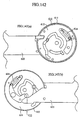
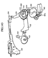


 fifth spacer,
 fifth plate spring,
 sixth spacer,
 sixth plate spring (bottom stage)