EP1321714B1 - A main liquid fuel injection device for a single combustion chamber, having a premixing chamber, of a gas turbine with low emission of pollutants - Google Patents
A main liquid fuel injection device for a single combustion chamber, having a premixing chamber, of a gas turbine with low emission of pollutants Download PDFInfo
- Publication number
- EP1321714B1 EP1321714B1 EP02258734A EP02258734A EP1321714B1 EP 1321714 B1 EP1321714 B1 EP 1321714B1 EP 02258734 A EP02258734 A EP 02258734A EP 02258734 A EP02258734 A EP 02258734A EP 1321714 B1 EP1321714 B1 EP 1321714B1
- Authority
- EP
- European Patent Office
- Prior art keywords
- injection device
- liquid fuel
- chamber
- combustion chamber
- pollutants
- Prior art date
- Legal status (The legal status is an assumption and is not a legal conclusion. Google has not performed a legal analysis and makes no representation as to the accuracy of the status listed.)
- Expired - Lifetime
Links
- 238000002485 combustion reaction Methods 0.000 title claims description 56
- 239000000446 fuel Substances 0.000 title claims description 51
- 238000002347 injection Methods 0.000 title claims description 48
- 239000007924 injection Substances 0.000 title claims description 48
- 239000007788 liquid Substances 0.000 title claims description 37
- 239000003344 environmental pollutant Substances 0.000 title claims description 19
- 231100000719 pollutant Toxicity 0.000 title claims description 19
- 238000001816 cooling Methods 0.000 claims description 14
- 230000007935 neutral effect Effects 0.000 claims description 3
- 239000007789 gas Substances 0.000 description 22
- MWUXSHHQAYIFBG-UHFFFAOYSA-N Nitric oxide Chemical compound O=[N] MWUXSHHQAYIFBG-UHFFFAOYSA-N 0.000 description 9
- OKTJSMMVPCPJKN-UHFFFAOYSA-N Carbon Chemical compound [C] OKTJSMMVPCPJKN-UHFFFAOYSA-N 0.000 description 7
- 238000002156 mixing Methods 0.000 description 6
- 206010016754 Flashback Diseases 0.000 description 4
- 239000000203 mixture Substances 0.000 description 4
- 230000015572 biosynthetic process Effects 0.000 description 3
- 229910052799 carbon Inorganic materials 0.000 description 3
- 230000006835 compression Effects 0.000 description 2
- 238000007906 compression Methods 0.000 description 2
- 230000008021 deposition Effects 0.000 description 2
- 238000012423 maintenance Methods 0.000 description 2
- 230000010355 oscillation Effects 0.000 description 2
- 238000011144 upstream manufacturing Methods 0.000 description 2
- UGFAIRIUMAVXCW-UHFFFAOYSA-N Carbon monoxide Chemical compound [O+]#[C-] UGFAIRIUMAVXCW-UHFFFAOYSA-N 0.000 description 1
- 229910002091 carbon monoxide Inorganic materials 0.000 description 1
- 238000009434 installation Methods 0.000 description 1
- 238000009533 lab test Methods 0.000 description 1
- 238000004519 manufacturing process Methods 0.000 description 1
- 230000001105 regulatory effect Effects 0.000 description 1
- 239000000243 solution Substances 0.000 description 1
Images


Classifications
-
- F—MECHANICAL ENGINEERING; LIGHTING; HEATING; WEAPONS; BLASTING
- F23—COMBUSTION APPARATUS; COMBUSTION PROCESSES
- F23R—GENERATING COMBUSTION PRODUCTS OF HIGH PRESSURE OR HIGH VELOCITY, e.g. GAS-TURBINE COMBUSTION CHAMBERS
- F23R3/00—Continuous combustion chambers using liquid or gaseous fuel
- F23R3/28—Continuous combustion chambers using liquid or gaseous fuel characterised by the fuel supply
- F23R3/286—Continuous combustion chambers using liquid or gaseous fuel characterised by the fuel supply having fuel-air premixing devices
-
- F—MECHANICAL ENGINEERING; LIGHTING; HEATING; WEAPONS; BLASTING
- F23—COMBUSTION APPARATUS; COMBUSTION PROCESSES
- F23C—METHODS OR APPARATUS FOR COMBUSTION USING FLUID FUEL OR SOLID FUEL SUSPENDED IN A CARRIER GAS OR AIR
- F23C2900/00—Special features of, or arrangements for combustion apparatus using fluid fuels or solid fuels suspended in air; Combustion processes therefor
- F23C2900/07001—Air swirling vanes incorporating fuel injectors
Definitions
- the present invention relates to a main liquid fuel injection device for a single combustion chamber, having a premixing chamber, of a gas turbine with low emission of pollutants.
- Air from the external environment is supplied to the compressor where it is pressurized.
- the pressurized air passes through a premixing chamber terminating in a nozzle or converging portion. At least one injector supplies fuel to this chamber, this fuel being mixed with the air to form a fuel-air mix for combustion.
- the fuel required for the combustion is therefore introduced into the combustion chamber from a pressurized network, the combustion process being designed to cause an increase in the temperature and enthalpy of the gas.
- a parallel fuel supply system for generating a pilot flame, is also generally provided in order to improve the stability characteristics of the flame.
- the gas at high temperature and high pressure passes through suitable ducts to reach the various stages of the turbine, which converts the enthalpy of the gas into mechanical energy which is available to a user.
- the prior art provides a premixing chamber immediately upstream from the combustion chamber.
- Both the premixing chamber and the combustion chamber are surrounded by a cavity containing pressurized air circulating in the opposite direction to the flow of combustion products leaving the combustion chamber.
- the aforesaid air (taken from the outlet of the axial compressor) is used as combustion air to be mixed with the fuel in the premixing chamber, and as cooling air for cooling the combustion chamber and the combustion products.
- the constriction is applied as a function of the quantity of fuel used, in such a way that the ratio between combustion air and fuel is kept constant at the optimal value.
- a set of burners is provided with converging axes positioned circumferentially around the outlet of the premixing chamber, so that a corresponding set of additional flames is created in the combustion region.
- These burners are supplied independently with additional fuel and with highpressure air obtained by further compression of the air supplied by the turbine's compressor; this air is sent to the burners through blades which are twisted so that an essentially helical motion is imparted to the air.
- the additional flames of the burners which are essentially pilot flames, not only is the main central combustion flame stabilized, preventing it from being extinguished, but, since the precise quantities of fuel and air used independently by the burners are known, the whole system can be regulated to achieve optimal and controlled ignition.
- liquid fuel injectors or main liquid fuel injection device provide a satisfactory distribution of the fuel-air mixture in the premixing chamber.
- the liquid fuel injector is provided with internal passages for the cooling air, these passages surrounding all the liquid fuel supply channels. This air is then injected into different points of the air and fuel premixing channel.
- Two examples of known injection devices are shown in JP 60 126521 and US 5 778 676 .
- the present invention seeks therefore to overcome the drawbacks mentioned above, and in particular to provide a main liquid fuel injection device for a single combustion chamber, having a premixing chamber, of a gas turbine, which ensures a low emission of pollutants.
- the present invention also seeks to provide a main liquid fuel injection device for a single combustion chamber, having a premixing chamber, of a gas turbine with low emission of pollutants which also provides good flame stability and reduces the pressure oscillations in the combustion chamber.
- the present invention still further seeks to provide a main liquid fuel injection device for a single combustion chamber, having a premixing chamber, of a gas turbine with low emission of pollutants which provides high combustion efficiency.
- the present invention also seeks to provide a main liquid fuel injection device for a single combustion chamber, having a premixing chamber, of a gas turbine with low emission of pollutants which enables the average life of components subject to high temperatures to be increased, by reducing the possibility of formation of carbon deposits.
- a main liquid fuel injection device for a single combustion chamber having a premixing chamber, of a gas turbine with low emission of pollutants, comprising a set of injection channels for the said liquid fuel distributed within the said premixing chamber, a set of blades extending radially with respect to the axis of symmetry of the said combustion chamber is provided, each of these blades being provided with at least one of the said injection channels, said blades having a neutral airfoil profile and extending along the axial direction, each blade having, on at least one lateral surface, at least one injection channel for the liquid fuel and at least one injection point for cooling air.
- the main liquid fuel injection device for a single combustion chamber having a premixing chamber, of a gas turbine with low emission of pollutants injects and atomizes the liquid fuel to be mixed with the air, thus creating a good distribution of fuel-air mixture before the inlet of the combustion chamber.
- the main liquid fuel injection device for a single combustion chamber, having a premixing chamber, of a gas turbine with low emission of pollutants also provides self-cooling of the walls which are subjected to high temperatures, and also makes it possible to protect the outer surfaces and the liquid fuel injection channels of the device against the damage caused by the deposition of carbon residues.
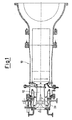
- the premixing chamber 12 also has a main liquid fuel injection device 20 according to the present invention, shown in greater detail in Figures 2 , 3 , 4 and 5 .
- the main injection device 20 comprises an elongate structure with axial symmetry, which tapers towards the combustion region within the premixing chamber 12.
- the device 20 has a base 22, which is generally circular and is fixed on the axis of the premixing chamber 12, for example by means of bolts passing through a circumferential set of holes 24.
- a cylindrical part 40 Upstream from the base 22 there is a cylindrical part 40 having a socket 38 for the entry of cooling air, a socket 39 for the entry of liquid fuel and inlets 37 for fixing flashback thermocouples, in other words safety devices for detecting flashback on to the said injection device 20.
- the injection device 20 is tapered through a large-radius connecting part 26 into an essentially cylindrical portion 28.
- the device 20 is tapered again up to a rounded end 30, which is also described as the "nose”.
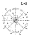
- a set of blades 32 consisting of eight blades for example, is provided around the cylindrical portion 28, the blades being positioned radially with respect to the axis of the device 20, at equal intervals.
- the blades 32 have a neutral airfoil profile and extend in the axial direction.
- Each blade 32 has, on at least one lateral surface, at least one injection channel 42 for the liquid fuel and at least one cooling air injection point 43.
- thermocouples Two flashback thermocouples are provided on the device 20. These thermocouples are easily installed in the correct position by means of the guides 36, shown in Figure 4 , which start in the inlet 37 and terminate in the proximity of the nose 30.
- thermocouples are provided both at the rounded end 30 and on the walls of the chamber 12.
- thermocouples on the rounded end 30 and four on the walls of the chamber 12.
- the liquid fuel is injected through the blades 32 tangentially, in other words in a perpendicular direction with respect to the flow of air passing through the blades 32.
- These blades 32 are located in the main duct of the premixing chamber 12, which receives air which has been preheated by the compression provided by the turbine's compressor.
- the cooling air is injected into the premixing chamber 12, from each blade 32 and also from the apex of the nose 30, this cooling air being used to keep the temperature of the liquid fuel supply channels 42 low, and thus prevent the formation of carbon residues.
- the cooling air is supplied to the inlet of the socket 38 at stabilized pressure and temperature.
- thermocouples starting with those positioned at the rounded end 30, detect dangerous flashbacks, and if these are detected they send information through transducers to the turbine control unit.
- combustion chambers used in the prior art in order to provide a distribution of the mixing between liquid fuel and air comparable to that obtained with the main injection device according to the present invention, use is made of multiple combustion chambers or chambers of annular shape with a plurality of injection points, instead of a single combustion chamber as in the case to which the present patent application relates.
- the main liquid fuel injection device for a single combustion chamber, having a premixing chamber, of a gas turbine with low emission of pollutants according to the present invention has yielded excellent results in laboratory tests, providing an excellent distribution of air and fuel mixing after the device, even when the position of the device along the axis is varied slightly.
Landscapes
- Engineering & Computer Science (AREA)
- Chemical & Material Sciences (AREA)
- Combustion & Propulsion (AREA)
- Mechanical Engineering (AREA)
- General Engineering & Computer Science (AREA)
- Turbine Rotor Nozzle Sealing (AREA)
- Combustion Methods Of Internal-Combustion Engines (AREA)
- Fuel-Injection Apparatus (AREA)
Applications Claiming Priority (2)
| Application Number | Priority Date | Filing Date | Title |
|---|---|---|---|
| ITMI20012780 | 2001-12-21 | ||
| IT2001MI002780A ITMI20012780A1 (it) | 2001-12-21 | 2001-12-21 | Dispositivo di iniezione principale di combustibile liquido per camera di combustione singola dotata di camera di pre-miscelamento di una tu |
Publications (3)
| Publication Number | Publication Date |
|---|---|
| EP1321714A2 EP1321714A2 (en) | 2003-06-25 |
| EP1321714A3 EP1321714A3 (en) | 2004-05-12 |
| EP1321714B1 true EP1321714B1 (en) | 2010-04-14 |
Family
ID=11448746
Family Applications (1)
| Application Number | Title | Priority Date | Filing Date |
|---|---|---|---|
| EP02258734A Expired - Lifetime EP1321714B1 (en) | 2001-12-21 | 2002-12-18 | A main liquid fuel injection device for a single combustion chamber, having a premixing chamber, of a gas turbine with low emission of pollutants |
Country Status (9)
Families Citing this family (19)
| Publication number | Priority date | Publication date | Assignee | Title |
|---|---|---|---|---|
| ITMI20012781A1 (it) * | 2001-12-21 | 2003-06-21 | Nuovo Pignone Spa | Assieme migliorato di camera di pre miscelamento e di camera di combustione, a basse emissioni inquinanti per turbine a gas con combustibile |
| US6691516B2 (en) * | 2002-07-15 | 2004-02-17 | Power Systems Mfg, Llc | Fully premixed secondary fuel nozzle with improved stability |
| US7165405B2 (en) * | 2002-07-15 | 2007-01-23 | Power Systems Mfg. Llc | Fully premixed secondary fuel nozzle with dual fuel capability |
| ITMI20032621A1 (it) * | 2003-12-30 | 2005-06-30 | Nuovo Pignone Spa | Sistema di combustione a basse emissioni inquinanti |
| EP1821035A1 (en) * | 2006-02-15 | 2007-08-22 | Siemens Aktiengesellschaft | Gas turbine burner and method of mixing fuel and air in a swirling area of a gas turbine burner |
| US20090255118A1 (en) * | 2008-04-11 | 2009-10-15 | General Electric Company | Method of manufacturing mixers |
| US20100024425A1 (en) * | 2008-07-31 | 2010-02-04 | General Electric Company | Turbine engine fuel nozzle |
| US8413446B2 (en) * | 2008-12-10 | 2013-04-09 | Caterpillar Inc. | Fuel injector arrangement having porous premixing chamber |
| DE102009045950A1 (de) * | 2009-10-23 | 2011-04-28 | Man Diesel & Turbo Se | Drallerzeuger |
| EP2325542B1 (en) * | 2009-11-18 | 2013-03-20 | Siemens Aktiengesellschaft | Swirler vane, swirler and burner assembly |
| US9395084B2 (en) * | 2012-06-06 | 2016-07-19 | General Electric Company | Fuel pre-mixer with planar and swirler vanes |
| US9975169B2 (en) | 2013-10-04 | 2018-05-22 | United Technologies Corporation | Additive manufactured fuel nozzle core for a gas turbine engine |
| WO2015122952A2 (en) | 2013-11-27 | 2015-08-20 | General Electric Company | Fuel nozzle with fluid lock and purge apparatus |
| WO2015147934A1 (en) | 2013-12-23 | 2015-10-01 | General Electric Company | Fuel nozzle structure for air-assisted fuel injection |
| EP3087322B1 (en) | 2013-12-23 | 2019-04-03 | General Electric Company | Fuel nozzle with flexible support structures |
| JP6611341B2 (ja) * | 2016-03-30 | 2019-11-27 | 三菱重工業株式会社 | 燃焼器、及びガスタービン |
| JP6634658B2 (ja) * | 2016-12-20 | 2020-01-22 | 三菱重工業株式会社 | メインノズル、燃焼器及びメインノズルの製造方法 |
| RU2769616C2 (ru) * | 2018-12-25 | 2022-04-04 | Ансальдо Энергия Свитзерленд Аг | Инжекционная головка для камеры сгорания газовой турбины |
| CA3217742A1 (en) * | 2021-05-12 | 2022-11-17 | Egidio PUCCI | Fuel injector and fuel nozzle for a gas turbine, and gas turbine engine including the nozzle |
Family Cites Families (26)
| Publication number | Priority date | Publication date | Assignee | Title |
|---|---|---|---|---|
| GB1139004A (en) * | 1966-02-28 | 1969-01-08 | Mini Of Technology | Improvements in or relating to combustion devices |
| US3682390A (en) * | 1970-05-13 | 1972-08-08 | Lucas Industries Ltd | Liquid atomizing devices |
| US4154056A (en) * | 1977-09-06 | 1979-05-15 | Westinghouse Electric Corp. | Fuel nozzle assembly for a gas turbine engine |
| US4263780A (en) * | 1979-09-28 | 1981-04-28 | General Motors Corporation | Lean prechamber outflow combustor with sets of primary air entrances |
| DE3241162A1 (de) * | 1982-11-08 | 1984-05-10 | Kraftwerk Union AG, 4330 Mülheim | Vormischbrenner mit integriertem diffusionsbrenner |
| JPS60126521A (ja) * | 1983-12-08 | 1985-07-06 | Nissan Motor Co Ltd | ガスタ−ビン用燃焼器の燃料噴射弁 |
| US5251447A (en) * | 1992-10-01 | 1993-10-12 | General Electric Company | Air fuel mixer for gas turbine combustor |
| FR2706588B1 (fr) * | 1993-06-16 | 1995-07-21 | Snecma | Système d'injection de carburant pour chambre de combustion. |
| US5351477A (en) * | 1993-12-21 | 1994-10-04 | General Electric Company | Dual fuel mixer for gas turbine combustor |
| GB9326367D0 (en) * | 1993-12-23 | 1994-02-23 | Rolls Royce Plc | Fuel injection apparatus |
| JP2666117B2 (ja) * | 1994-06-10 | 1997-10-22 | 財団法人石油産業活性化センター | 予蒸発予混合燃焼器 |
| US5511375A (en) * | 1994-09-12 | 1996-04-30 | General Electric Company | Dual fuel mixer for gas turbine combustor |
| US5778676A (en) * | 1996-01-02 | 1998-07-14 | General Electric Company | Dual fuel mixer for gas turbine combustor |
| JPH09210364A (ja) * | 1996-02-06 | 1997-08-12 | Nissan Motor Co Ltd | ガスタービンの予混合燃焼器 |
| US5857320A (en) * | 1996-11-12 | 1999-01-12 | Westinghouse Electric Corporation | Combustor with flashback arresting system |
| US5735466A (en) * | 1996-12-20 | 1998-04-07 | United Technologies Corporation | Two stream tangential entry nozzle |
| EP0936406B1 (en) * | 1998-02-10 | 2004-05-06 | General Electric Company | Burner with uniform fuel/air premixing for low emissions combustion |
| US6178752B1 (en) * | 1998-03-24 | 2001-01-30 | United Technologies Corporation | Durability flame stabilizing fuel injector with impingement and transpiration cooled tip |
| US6082111A (en) * | 1998-06-11 | 2000-07-04 | Siemens Westinghouse Power Corporation | Annular premix section for dry low-NOx combustors |
| US6094904A (en) * | 1998-07-16 | 2000-08-01 | United Technologies Corporation | Fuel injector with a replaceable sensor |
| WO2000011404A1 (de) * | 1998-08-20 | 2000-03-02 | Siemens Aktiengesellschaft | Verfahren zum betrieb eines hybridbrenners |
| RU2162988C2 (ru) * | 1999-02-22 | 2001-02-10 | Открытое акционерное общество "Авиадвигатель" | Камера сгорания газотурбинной установки |
| JP2001108237A (ja) * | 1999-10-07 | 2001-04-20 | Hitachi Ltd | ガスタービン燃焼装置 |
| JP2001280641A (ja) * | 2000-03-31 | 2001-10-10 | Mitsubishi Heavy Ind Ltd | ガスタービン燃焼器、および、ガスタービン燃焼器における燃料と空気の混合方法 |
| JP2002031343A (ja) * | 2000-07-13 | 2002-01-31 | Mitsubishi Heavy Ind Ltd | 燃料噴出部材、バーナ、燃焼器の予混合ノズル、燃焼器、ガスタービン及びジェットエンジン |
| JP2002039533A (ja) * | 2000-07-21 | 2002-02-06 | Mitsubishi Heavy Ind Ltd | 燃焼器、ガスタービン及びジェットエンジン |
-
2001
- 2001-12-21 IT IT2001MI002780A patent/ITMI20012780A1/it unknown
-
2002
- 2002-12-05 CA CA002413635A patent/CA2413635C/en not_active Expired - Fee Related
- 2002-12-10 TW TW091135689A patent/TWI296697B/zh not_active IP Right Cessation
- 2002-12-17 US US10/320,680 patent/US6834506B2/en not_active Expired - Fee Related
- 2002-12-18 DE DE60235948T patent/DE60235948D1/de not_active Expired - Lifetime
- 2002-12-18 EP EP02258734A patent/EP1321714B1/en not_active Expired - Lifetime
- 2002-12-20 KR KR1020020081805A patent/KR100760558B1/ko not_active Expired - Fee Related
- 2002-12-20 JP JP2002369155A patent/JP4490034B2/ja not_active Expired - Fee Related
- 2002-12-20 RU RU2002134608/06A patent/RU2320926C2/ru not_active IP Right Cessation
Also Published As
| Publication number | Publication date |
|---|---|
| KR20030053434A (ko) | 2003-06-28 |
| US20030121266A1 (en) | 2003-07-03 |
| CA2413635C (en) | 2009-10-13 |
| KR100760558B1 (ko) | 2007-09-20 |
| ITMI20012780A1 (it) | 2003-06-21 |
| DE60235948D1 (de) | 2010-05-27 |
| RU2320926C2 (ru) | 2008-03-27 |
| TW200409887A (en) | 2004-06-16 |
| JP4490034B2 (ja) | 2010-06-23 |
| TWI296697B (en) | 2008-05-11 |
| JP2003207130A (ja) | 2003-07-25 |
| EP1321714A2 (en) | 2003-06-25 |
| US6834506B2 (en) | 2004-12-28 |
| EP1321714A3 (en) | 2004-05-12 |
| CA2413635A1 (en) | 2003-06-21 |
Similar Documents
| Publication | Publication Date | Title |
|---|---|---|
| EP1321714B1 (en) | A main liquid fuel injection device for a single combustion chamber, having a premixing chamber, of a gas turbine with low emission of pollutants | |
| EP1431543B1 (en) | Injector | |
| EP3320268B1 (en) | Burner for a gas turbine and method for operating the burner | |
| EP1371906B1 (en) | Gas turbine engine combustor can with trapped vortex cavity | |
| EP1426689B1 (en) | Gas turbine combustor having staged burners with dissimilar mixing passage geometries | |
| KR960003680B1 (ko) | 연소기의 연료노즐 구조 | |
| JP4177812B2 (ja) | タービンエンジンの燃料ノズル | |
| EP3282191B1 (en) | Pilot premix nozzle and fuel nozzle assembly | |
| EP2626635B1 (en) | Combustor assembly with trapped vortex cavity | |
| EP2738355B1 (en) | A gas turbine engine system and an associated method thereof | |
| US11371706B2 (en) | Premixed pilot nozzle for gas turbine combustor | |
| EP4174379B1 (en) | Methods of operating a turbomachine combustor on hydrogen | |
| EP3211318B1 (en) | Gas-only cartridge for a premix fuel nozzle | |
| EP1672282B1 (en) | Method and apparatus for decreasing combustor acoustics | |
| EP1321715B1 (en) | Improved combination of a premixing chamber and a combustion chamber, with low emission of pollutants, for gas turbines running on liquid and/or gas fuel | |
| JP3192055B2 (ja) | ガスタービン燃焼器 | |
| US9103552B2 (en) | Burner assembly including a fuel distribution ring with a slot and recess | |
| US12404813B2 (en) | Control method for gas turbine combustor and control device for gas turbine combustor | |
| EP2068076A2 (en) | Improvements in or relating to burners for a gas-turbine engine | |
| US20200018232A1 (en) | Independently controlled three stage water injection in a diffusion burner | |
| EP1985920A2 (en) | Combustor and a fuel suppy method for the combustor |
Legal Events
| Date | Code | Title | Description |
|---|---|---|---|
| PUAI | Public reference made under article 153(3) epc to a published international application that has entered the european phase |
Free format text: ORIGINAL CODE: 0009012 |
|
| AK | Designated contracting states |
Designated state(s): AT BE BG CH CY CZ DE DK EE ES FI FR GB GR IE IT LI LU MC NL PT SE SI SK TR |
|
| AX | Request for extension of the european patent |
Extension state: AL LT LV MK RO |
|
| PUAL | Search report despatched |
Free format text: ORIGINAL CODE: 0009013 |
|
| AK | Designated contracting states |
Kind code of ref document: A3 Designated state(s): AT BE BG CH CY CZ DE DK EE ES FI FR GB GR IE IT LI LU MC NL PT SE SI SK TR |
|
| AX | Request for extension of the european patent |
Extension state: AL LT LV MK RO |
|
| 17P | Request for examination filed |
Effective date: 20041112 |
|
| AKX | Designation fees paid |
Designated state(s): CH DE FR GB LI NL |
|
| 17Q | First examination report despatched |
Effective date: 20080229 |
|
| GRAP | Despatch of communication of intention to grant a patent |
Free format text: ORIGINAL CODE: EPIDOSNIGR1 |
|
| GRAS | Grant fee paid |
Free format text: ORIGINAL CODE: EPIDOSNIGR3 |
|
| GRAA | (expected) grant |
Free format text: ORIGINAL CODE: 0009210 |
|
| AK | Designated contracting states |
Kind code of ref document: B1 Designated state(s): CH DE FR GB LI NL |
|
| REG | Reference to a national code |
Ref country code: GB Ref legal event code: FG4D |
|
| REG | Reference to a national code |
Ref country code: CH Ref legal event code: EP Ref country code: CH Ref legal event code: NV Representative=s name: SERVOPATENT GMBH |
|
| REF | Corresponds to: |
Ref document number: 60235948 Country of ref document: DE Date of ref document: 20100527 Kind code of ref document: P |
|
| REG | Reference to a national code |
Ref country code: NL Ref legal event code: T3 |
|
| PLBE | No opposition filed within time limit |
Free format text: ORIGINAL CODE: 0009261 |
|
| STAA | Information on the status of an ep patent application or granted ep patent |
Free format text: STATUS: NO OPPOSITION FILED WITHIN TIME LIMIT |
|
| 26N | No opposition filed |
Effective date: 20110117 |
|
| PGFP | Annual fee paid to national office [announced via postgrant information from national office to epo] |
Ref country code: GB Payment date: 20141229 Year of fee payment: 13 Ref country code: CH Payment date: 20141229 Year of fee payment: 13 |
|
| PGFP | Annual fee paid to national office [announced via postgrant information from national office to epo] |
Ref country code: FR Payment date: 20141217 Year of fee payment: 13 Ref country code: NL Payment date: 20141226 Year of fee payment: 13 |
|
| PGFP | Annual fee paid to national office [announced via postgrant information from national office to epo] |
Ref country code: DE Payment date: 20141230 Year of fee payment: 13 |
|
| REG | Reference to a national code |
Ref country code: DE Ref legal event code: R119 Ref document number: 60235948 Country of ref document: DE |
|
| REG | Reference to a national code |
Ref country code: CH Ref legal event code: PL |
|
| GBPC | Gb: european patent ceased through non-payment of renewal fee |
Effective date: 20151218 |
|
| REG | Reference to a national code |
Ref country code: NL Ref legal event code: MM Effective date: 20160101 |
|
| REG | Reference to a national code |
Ref country code: FR Ref legal event code: ST Effective date: 20160831 |
|
| PG25 | Lapsed in a contracting state [announced via postgrant information from national office to epo] |
Ref country code: LI Free format text: LAPSE BECAUSE OF NON-PAYMENT OF DUE FEES Effective date: 20151231 Ref country code: DE Free format text: LAPSE BECAUSE OF NON-PAYMENT OF DUE FEES Effective date: 20160701 Ref country code: GB Free format text: LAPSE BECAUSE OF NON-PAYMENT OF DUE FEES Effective date: 20151218 Ref country code: NL Free format text: LAPSE BECAUSE OF NON-PAYMENT OF DUE FEES Effective date: 20160101 Ref country code: CH Free format text: LAPSE BECAUSE OF NON-PAYMENT OF DUE FEES Effective date: 20151231 |
|
| PG25 | Lapsed in a contracting state [announced via postgrant information from national office to epo] |
Ref country code: FR Free format text: LAPSE BECAUSE OF NON-PAYMENT OF DUE FEES Effective date: 20151231 |