EP1321330A2 - Motor-driven vehicle and control method thereof - Google Patents
Motor-driven vehicle and control method thereof Download PDFInfo
- Publication number
- EP1321330A2 EP1321330A2 EP02028509A EP02028509A EP1321330A2 EP 1321330 A2 EP1321330 A2 EP 1321330A2 EP 02028509 A EP02028509 A EP 02028509A EP 02028509 A EP02028509 A EP 02028509A EP 1321330 A2 EP1321330 A2 EP 1321330A2
- Authority
- EP
- European Patent Office
- Prior art keywords
- vehicle
- motor
- reduction
- connection state
- electric power
- Prior art date
- Legal status (The legal status is an assumption and is not a legal conclusion. Google has not performed a legal analysis and makes no representation as to the accuracy of the status listed.)
- Withdrawn
Links
- 238000000034 method Methods 0.000 title claims description 21
- 239000000446 fuel Substances 0.000 claims description 91
- 230000009467 reduction Effects 0.000 claims description 80
- 238000007599 discharging Methods 0.000 claims description 4
- 238000010248 power generation Methods 0.000 abstract description 9
- 230000001172 regenerating effect Effects 0.000 description 7
- 230000008929 regeneration Effects 0.000 description 7
- 238000011069 regeneration method Methods 0.000 description 7
- 238000010276 construction Methods 0.000 description 5
- XLYOFNOQVPJJNP-UHFFFAOYSA-N water Substances O XLYOFNOQVPJJNP-UHFFFAOYSA-N 0.000 description 5
- 238000002485 combustion reaction Methods 0.000 description 4
- 238000012937 correction Methods 0.000 description 4
- 238000006243 chemical reaction Methods 0.000 description 3
- 230000008569 process Effects 0.000 description 3
- 230000005672 electromagnetic field Effects 0.000 description 2
- 230000008014 freezing Effects 0.000 description 2
- 238000007710 freezing Methods 0.000 description 2
- 239000007789 gas Substances 0.000 description 2
- UFHFLCQGNIYNRP-UHFFFAOYSA-N Hydrogen Chemical compound [H][H] UFHFLCQGNIYNRP-UHFFFAOYSA-N 0.000 description 1
- 238000004378 air conditioning Methods 0.000 description 1
- 230000000994 depressogenic effect Effects 0.000 description 1
- 150000002431 hydrogen Chemical class 0.000 description 1
- 239000001257 hydrogen Substances 0.000 description 1
- 229910052739 hydrogen Inorganic materials 0.000 description 1
- 230000007246 mechanism Effects 0.000 description 1
- 238000012986 modification Methods 0.000 description 1
- 230000004048 modification Effects 0.000 description 1
- 238000012544 monitoring process Methods 0.000 description 1
- 238000012545 processing Methods 0.000 description 1
- 238000005086 pumping Methods 0.000 description 1
- 230000001360 synchronised effect Effects 0.000 description 1
- 238000010792 warming Methods 0.000 description 1
Images



Classifications
-
- B—PERFORMING OPERATIONS; TRANSPORTING
- B60—VEHICLES IN GENERAL
- B60L—PROPULSION OF ELECTRICALLY-PROPELLED VEHICLES; SUPPLYING ELECTRIC POWER FOR AUXILIARY EQUIPMENT OF ELECTRICALLY-PROPELLED VEHICLES; ELECTRODYNAMIC BRAKE SYSTEMS FOR VEHICLES IN GENERAL; MAGNETIC SUSPENSION OR LEVITATION FOR VEHICLES; MONITORING OPERATING VARIABLES OF ELECTRICALLY-PROPELLED VEHICLES; ELECTRIC SAFETY DEVICES FOR ELECTRICALLY-PROPELLED VEHICLES
- B60L58/00—Methods or circuit arrangements for monitoring or controlling batteries or fuel cells, specially adapted for electric vehicles
- B60L58/30—Methods or circuit arrangements for monitoring or controlling batteries or fuel cells, specially adapted for electric vehicles for monitoring or controlling fuel cells
- B60L58/32—Methods or circuit arrangements for monitoring or controlling batteries or fuel cells, specially adapted for electric vehicles for monitoring or controlling fuel cells for controlling the temperature of fuel cells, e.g. by controlling the electric load
- B60L58/34—Methods or circuit arrangements for monitoring or controlling batteries or fuel cells, specially adapted for electric vehicles for monitoring or controlling fuel cells for controlling the temperature of fuel cells, e.g. by controlling the electric load by heating
-
- B—PERFORMING OPERATIONS; TRANSPORTING
- B60—VEHICLES IN GENERAL
- B60L—PROPULSION OF ELECTRICALLY-PROPELLED VEHICLES; SUPPLYING ELECTRIC POWER FOR AUXILIARY EQUIPMENT OF ELECTRICALLY-PROPELLED VEHICLES; ELECTRODYNAMIC BRAKE SYSTEMS FOR VEHICLES IN GENERAL; MAGNETIC SUSPENSION OR LEVITATION FOR VEHICLES; MONITORING OPERATING VARIABLES OF ELECTRICALLY-PROPELLED VEHICLES; ELECTRIC SAFETY DEVICES FOR ELECTRICALLY-PROPELLED VEHICLES
- B60L58/00—Methods or circuit arrangements for monitoring or controlling batteries or fuel cells, specially adapted for electric vehicles
- B60L58/30—Methods or circuit arrangements for monitoring or controlling batteries or fuel cells, specially adapted for electric vehicles for monitoring or controlling fuel cells
-
- Y—GENERAL TAGGING OF NEW TECHNOLOGICAL DEVELOPMENTS; GENERAL TAGGING OF CROSS-SECTIONAL TECHNOLOGIES SPANNING OVER SEVERAL SECTIONS OF THE IPC; TECHNICAL SUBJECTS COVERED BY FORMER USPC CROSS-REFERENCE ART COLLECTIONS [XRACs] AND DIGESTS
- Y02—TECHNOLOGIES OR APPLICATIONS FOR MITIGATION OR ADAPTATION AGAINST CLIMATE CHANGE
- Y02T—CLIMATE CHANGE MITIGATION TECHNOLOGIES RELATED TO TRANSPORTATION
- Y02T90/00—Enabling technologies or technologies with a potential or indirect contribution to GHG emissions mitigation
- Y02T90/40—Application of hydrogen technology to transportation, e.g. using fuel cells
Definitions
- the present invention relates to a motor-driven vehicle which uses a motor as its driving force source, and to a control method thereof.
- an engine-driven vehicle a fine control of the vehicle speed can be easily performed by reducing a depression amount of an accelerator pedal, namely by applying a so-called engine brake, which originates from a friction loss, pumping loss, and the like, in the internal combustion engine.
- engine brake is effectively used for decelerating the vehicle speed in a relatively high vehicle speed range, whereby the amount of load which may otherwise be applied on a mechanical braking system of the vehicle can be reduced.
- a motor-driven vehicle in the case of a vehicle including only a motor as its driving force source (will hereinafter be referred to as "a motor-driven vehicle"), even when the depression amount of the accelerator pedal is reduced, the motor that generally has a small friction loss as compared to an internal combustion engine continues to rotate due to an inertial force, thus generating driving force. With such a motor-driven vehicle, it is therefore difficult to obtain an adequate braking force such as that obtained by applying an engine brake as described above. Accordingly, as compared to engine-driven vehicles, motor-driven vehicles involve a problem related to the poor vehicle drivability attributed to the difficulty in adjusting the vehicle speed by the accelerator pedal.
- a regenerative brake is also used for applying the brake on the vehicle. This does not eliminate, however, the necessity for enforcing mechanical braking systems in a motor-driven vehicle, since the regenerative brake can no longer be used when a secondary battery has been charged to its full capacity.
- a vehicle includes a motor for outputting a vehicle required power to the vehicle, fuel cell system for generating an electric power, temperature detecting means for detecting the temperature of the fuel cell system, electric power consuming means for consuming an electric power, and switching device control means.
- the switching device is arranged to selectively switch a connection state among a first connection state wherein the fuel cell system and the electric power consuming means are connected, second connection state wherein the motor and the electric power consuming means are connected, and third connection state wherein the fuel cell system and the motor are connected.
- the switching device control means is adapted to control the switching device so as to establish the first connection state when the temperature of the fuel cell system detected by the temperature detecting means is equal to or lower than a predetermined temperature.
- the electric power consuming means is selectively connected to either one of the fuel cell system and motor.
- the warming-up operation of the fuel cell system can be accelerated and the drive motor can be used as a power generation braking device for applying the brake on the vehicle. That is, when the temperature of the fuel cell system is equal to or lower than the predetermined temperature, the electric power consuming means is connected to the fuel cell system so that the fuel cell system is operated under a high load, thus accelerating the warming-up operation thereof.
- the electric power consuming means is a variable resistor whose resistance value increases as the temperature detected by the temperature detecting means reduces below the predetermined temperature.
- an appropriate amount of load can be applied on the fuel cell system in accordance with its temperature, whereby the time required for completing the warming-up operation of the fuel cell system can be reduced regardless of its temperature.
- the vehicle according to the first aspect invention further includes a reduction detecting means for detecting a reduction in the vehicle required power, a motor control means is adapted to operate the motor as a braking means for applying the brake on the vehicle when a reduction in the vehicle required power is detected, and the switching device control means is adapted to control the switching device so as to establish the second connection state when a reduction in the vehicle required power is detected.
- a reduction detecting means for detecting a reduction in the vehicle required power
- a motor control means is adapted to operate the motor as a braking means for applying the brake on the vehicle when a reduction in the vehicle required power is detected
- the switching device control means is adapted to control the switching device so as to establish the second connection state when a reduction in the vehicle required power is detected.
- the vehicle according to the first aspect of the invention further includes an accelerator pedal for inputting the vehicle required power and vehicle speed detecting means for detecting a vehicle speed of the vehicle, and the reduction detecting means is adapted to detect a reduction in the vehicle required power when the depression amount of the accelerator pedal is equal to or smaller than a predetermined value and the vehicle speed detected by the vehicle speed detecting means is equal to or higher than a predetermined value. Accordingly, further accuracy is achieved in detecting a reduction in the vehicle required power.
- the electric power consuming means is a variable resistor whose resistance value increases as the depression amount of the accelerator pedal reduces below the predetermined value. In this case, an electric power can be appropriately consumed in accordance with the degree of reduction in the vehicle required power.
- the vehicle according to the first aspect of the invention further includes a reduction detecting means for detecting a reduction in the vehicle required power and the switching device control means is adapted to control the switching device so as to establish the third connection state when a reduction in the vehicle required power is not detected and the detected temperature of the fuel cell system is higher than the predetermined temperature.
- the motor-driven vehicle operates in a normal operating state.
- a vehicle includes a motor for outputting a vehicle required power to the vehicle, power supply for supplying a power to the motor, reduction detecting means for detecting a reduction in the vehicle required power, motor control means, electric power consuming means, switching device, and switching device control means.
- the motor control means is adapted to operate the motor as a braking means for applying the brake on the vehicle when a reduction in the vehicle required power is detected.
- the electric power consuming means is arranged to consume the electric power that is generated by the motor while it is operating as the braking means.
- the switching device is arranged to selectively switch a connection state between a first connection state wherein the motor and the electric power consuming means are connected and a second connection state wherein the power supply and the motor are connected.
- the switching device control means is adapted to control the switching device so as to establish the first connection state when the reduction detecting means detects a reduction in the vehicle required power.
- the amount of load to be applied on the mechanical braking system can be reduced by using the motor as the braking means when a reduction in the vehicle required power is detected. Also, since the electric power that is generated by the motor while it is operating as the braking means is consumed by the electric power consuming means, the motor can be used for applying the brake on the vehicle even when a power regeneration is not allowed. Accordingly, the drivability of the motor-driven vehicle can be improved.
- the vehicle according to the second aspect of the invention further includes an accelerator pedal for inputting the vehicle required power and the reduction detecting means is adapted to detect a reduction in the vehicle required power when the depression mount of the accelerator pedal changes to a smaller value.
- the reduction detecting means is adapted to detect a reduction in the vehicle required power when the depression mount of the accelerator pedal changes to a smaller value.
- a reduction in the vehicle-required power is detected on the basis of the operation of the accelerator pedal, whereby the motor-driven vehicle can have as a good drivability as that of an engine-driven vehicle.
- the electric power consuming means is a variable resistor whose resistance value increases as the depression amount of the accelerator pedal reduces or a motor for driving an auxiliary, which motor is driven when a reduction in the vehicle required power is detected.
- the electric power consuming means is such a variable resistor or motor, the electric power consuming means acts as a load on the motor when it is operating as a power generator. Thus, the rotation speed of the motor is reduced and a braking force is thereby generated.
- the vehicle according to the second aspect of the invention further includes an accelerator pedal for inputting the vehicle required power and vehicle speed detecting means for detecting the vehicle speed of the vehicle, and the reduction detecting means is adapted to detect a reduction in the vehicle required power when the depression amount of the accelerator pedal is equal to or smaller than a predetermined value and the vehicle speed detected by the vehicle speed detecting means is equal to or higher than a predetermined value.
- the reduction detecting means is adapted to detect a reduction in the vehicle required power when the depression amount of the accelerator pedal is equal to or smaller than a predetermined value and the vehicle speed detected by the vehicle speed detecting means is equal to or higher than a predetermined value.
- the power supply is a fuel cell system or consists of a fuel cell system and secondary battery.
- the vehicles uses only the fuel cell system as the power supply.
- the vehicle uses the fuel cell system and secondary battery as the power supply.
- a vehicle includes a motor for outputting a vehicle required power to the vehicle, secondary battery for charging and discharging an electric power, electric power consuming means for consuming an electric power, switching device, reduction detecting means for detecting a reduction in the vehicle required power, the motor control means is adapted to operate the motor as a braking means for applying the brake on the vehicle when a reduction in the vehicle required power is detected, and switching device control means.
- the switching device is arranged to selectively switch a connection state between a first connection state wherein the motor and the electric power consuming means are connected and a second connection state wherein the secondary battery and the motor are connected.
- the switching device control means is adapted to control the switching device so as to establish the first connection state when a reduction in the vehicle required power is detected and the charged capacity of the secondary battery is equal to or larger than a predetermined value.
- the electric power consuming means begins to consume the power that is generated by the motor operating as the braking means when a reduction in the vehicle required power is detected while the charged capacity of the secondary battery is equal to or larger than the predetermined value.
- the motor can be used for applying the brake on the vehicle and the amount of load to be applied on the mechanical braking system can be thereby reduced even when a power regeneration is not allowed.
- the electric power is thus consumed by the electric power consuming means, it reduces the rotation speed of the motor, whereby the drivability of the motor-driven vehicle can be improved.
- the switching device control means is adapted to control the switching device so as to establish the second connection state when a reduction in the vehicle required power is detected and the charged capacity of the secondary battery is smaller than the predetermined value. In this case, a means of the power that has been consumed by the motor can be regained, which results in an improved energy efficiency of the vehicle.
- the vehicle according to the third aspect of the invention further includes a fuel cell system as a main power supply and the switching device is arranged to selectively switch a connection state among the first connection state, the second connection state, and a third connection state wherein the fuel cell system and the motor are connected, and the switching device control means is adapted to control the switching device so as to establish the third connection state when a reduction in the vehicle required power is not detected.
- the motor can operate using the power supplied from the fuel cell system and a means of the power which has been consumed by the motor can be regained and charged in the secondary battery.
- a braking control method is used in a vehicle including a motor for outputting a vehicle required power, fuel cell system for generating an electric power, temperature detecting means for detecting the temperature of the fuel cell system, and electric power consuming means for consuming an electric power.
- the braking control method includes detecting a temperature of the fuel cell system by means of the temperature detecting means, determining whether the temperature of the fuel cell system is equal to or lower than a predetermined temperature, and establishing a first connection state selected from the first connection state wherein the fuel cell system and the electric power consuming means are connected, a second connection state wherein the motor and the electric power consuming means are connected, and a third connection state wherein the fuel cell system and the motor are connected, when the temperature of the fuel cell system is equal to or lower than the predetermined temperature.
- the electric power consuming means is selectively connected to either one of the fuel cell system and the motor, whereby the warming-up operation of the fuel cell system can be accelerated and the drive motor can be used as a power generation braking device for applying the brake on the vehicle. That is, when the temperature of the fuel cell system is equal to or lower than the predetermined temperature, the electric power consuming means is connected to the fuel cell system so that the fuel cell system is operated under a high load, thus accelerating the warming-up operation thereof.
- a braking control method is used in a vehicle including a motor for outputting a vehicle required power to the vehicle, a power supply for supplying a power to the motor, a reduction detecting means for detecting a reduction in the vehicle required power, a motor control means which operates the motor as a braking means for applying the brake on the vehicle when a reduction in the vehicle required power is detected, and an electric power consuming means for consuming an electric power generated by the motor being operated as the braking means.
- the braking control method includes establishing a first connection state selected from the first connection state wherein the motor and the electric power consuming means are connected and a second connection state wherein the power supply and the motor are connected when the reduction detecting means detects a reduction in the vehicle required power.
- the amount of load to be applied on the mechanical braking system can be reduced by using the motor as the braking means when a reduction in the vehicle required power is detected. Also, since the electric power that is generated by the motor while it is operating as the braking means is consumed by the electric power consuming means, the motor can be used for applying the brake on the vehicle even when a power regeneration is not allowed. Accordingly, the drivability of the motor-driven vehicle can be improved.
- a braking control method is used in a vehicle including a motor for outputting a vehicle required power to the vehicle, secondary battery for charging and discharging an electric power, electric power consuming means for consuming an electric power, reduction detecting means for detecting a reduction in the vehicle required power, and a motor control means which operates the motor as a braking means for applying the brake on the vehicle when a reduction in the vehicle required power is detected.
- This braking control method includes detecting the charged capacity of the secondary battery, determining whether the charged capacity of the secondary battery is equal to or larger than a predetermined value, and establishing a first connection state selected from the first connection state wherein the motor and the electric power consuming means are connected and a second connection state wherein the secondary battery and the motor are connected, when a reduction in the vehicle required power is detected and the charged capacity of the secondary battery is equal to or larger than the predetermined value.
- the amount of load to be applied on the mechanical braking system can be reduced by using the motor as the braking means when a reduction in the vehicle required power is detected.
- the motor can be used for applying the brake on the vehicle even when a power regeneration is not allowed.
- the drivability of the motor-driven vehicle can be improved.
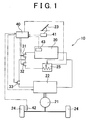
- Fig. 1 schematically shows the construction of a motor-driven vehicle 10 which includes a fuel cell system 20, drive motor 21, inverter 22, accelerator pedal 23, wheels 24, and variable resistor 25.
- the fuel cell system 20 serves as a power supply of the motor-driven vehicle 10.
- the drive motor 21 is operated to convert an electric power supplied from the power supply into a driving force.
- the inverter 22 is adapted to control the operation of the drive motor 21.
- the accelerator pedal 23 is used for inputting a vehicle required power, a power required to be output to the vehicle 10.
- the wheels 24 are driven by the drive motor 21.
- the resistance value of the variable resistor 25 can be continuously changed.
- the fuel cell system 20, inverter 22, and variable resistor 25 are connected via power lines such that three different closed electric circuits can be selectively established. More specifically, when the vehicle required power is reduced (i.e., when a braking force is required), a first relay 31 is opened while second and third relays 32, 33 are closed to establish a closed circuit in which the inverter 22 and the variable resistor 25 are connected in series. Under the normal operating state of the vehicle, the second relay 32 is opened while the first and third relays 31, 33 are closed to establish a closed circuit in which the fuel cell system 20 and the inverter 22 are connected in series. When performing a warming-up operation of the fuel cell system 20, the third relay 33 is opened while the first and second relays 31, 32 are closed to establish a closed circuit in which the fuel cell system 20 and the variable resistor 25 are connected in series.
- the motor-driven vehicle 10 is provided with an electronic control unit (ECU) 40.
- the ECU 40 is arranged to control the operation of the fuel cell system 20 and drive motor 21, the opening and closing operation of the relays 31, 32, and 33, and the resistance value of the variable resistor 25.
- the ECU 40 includes a central processing unit (CPU), recording mediums (RAM, ROM), and other components, which are not shown in the figure.
- the ECU 40 are connected via signal lines to various sensors for detecting operation conditions of the motor-driven vehicle 10, such as an accelerator opening sensor 41 that detects the depression amount of an accelerator pedal as "accelerator opening ⁇ ", vehicle speed sensor 42 which is disposed in the vicinity of one of the wheels 24 for detecting the vehicle speed, and temperature sensor 43 for detecting the temperature of the fuel cell system 20.
- the ECU 40 are also connected via signal lines to the respective relays 31, 32, and 33, inverter 22, and variable resistor 25.
- the fuel cell system 20 is a battery system which generates an electric power using a reformed gas which is produced by a reformer (not shown) and includes hydrogen, or a hydrogen gas as a fuel.
- a fuel supply system for supplying reformed gas, air, and the like is not shown in the figures.
- the drive motor 21 is a three-phase synchronous motor including a rotor provided with a plurality of permanent magnets disposed on its periphery, and a stator wound with wires to form a three-phase coil.
- the rotor of the drive motor 21 is connected via a gear mechanism, or the like, to the wheels 24.
- a driving force is generated and output to the wheels 24 when the rotor is driven to rotate by mutual reactions that occur between an electromagnetic field produced by each permanent magnet of the rotor and that produced by the three-phase coil of the stator.
- a deceleration requirement a braking requirement
- the drive motor 21 begins to operate as a power generation braking device.
- the rotor of the drive motor 21 is driven by an external force and the mutual reactions between the electromagnetic fields are thereby caused so that electromotive forces are generated at respective ends of the three-phase coil.
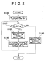
- Fig. 2 is a flowchart of a control routine that is executed when performing the warming-up operation of the fuel cell system 20
- Fig. 3 shows one example of a map used for determining the resistance value of the variable resistor 25 during the warming-up operation of the fuel cell system 20.
- This control routine begins, for example, when a requirement for starting the operation of the motor-driven vehicle 10 is made.
- the relays 31, 32, and 33 are all open before beginning this routine.
- the ECU 40 first detects a temperature Tfc of the fuel cell system 20 via the temperature sensor 43 (step S100), and then determines whether the detected temperature Tfc is equal to or lower than a reference temperature Tref (step S110).
- the reference temperature Tref is set to 0 °C, for example, whether the water produced during the operation of the fuel cell system 20 (will hereinafter be described as "the resultant water" can be frozen is determined in this step.
- step S110 NO
- the ECU 40 therefore closes the first and third relays 31, 33 while opening the second relay 32 (step S140), after which the routine ends.
- step S110 When the temperature Tfc is equal to or lower than the reference temperature Tref (step S110: YES), conversely, the ECU 40 closes the first and second relays 31, 32 and opens the third relay 33 so that the fuel cell system 20 and variable resistor 25 are connected in series (step S120). Subsequently, the ECU 40 determines a variable resistance value Rv of the variable resistor 25 in accordance with the detected temperature Tfc of the fuel cell system 20 using a map as shown in Fig. 3, and sets the resistance value of the variable resistor 25 to the determined variable resistance value Rv (step S130), after which the ECU 40 returns to the step S110. Thus, these steps S120 to S130 are repeated until the ECU 40 determines that the temperature Tfc of the fuel cell system 20 is higher than the reference temperature Tref, namely until the warming-up operation of the fuel cell system 20 has been completed.
- a horizontal axis represents the temperature Tfc of the fuel cell system 20 while a vertical axis represents the variable resistance value Rv.
- the variable resistance value Rv increases as the detected temperature Tfc reduces.
- Fig. 4 is a flowchart of a vehicle braking control routine executed in the motor-driven vehicle of the first embodiment.
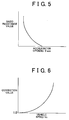
- Fig. 5 shows one example of a map used for determining a basic resistance value in accordance with an accelerator opening ⁇ acc
- Fig. 6 shows one example of a map used for determining a correction value corresponding to the basic resistance value in accordance with a vehicle speed Vc.
- this braking control routine needs to be executed appropriately when the vehicle required power is reduced (i.e., when a requirement for decelerating the vehicle or applying the brake on the vehicle is made), it is repeatedly executed at predetermined time intervals.
- the ECU 40 first detects the accelerator opening ⁇ acc via the accelerator opening sensor 41 and detects the vehicle speed Vc via the speed sensor 42 (step S200).
- the ECU 40 determines whether the detected accelerator opening ⁇ acc is equal to or smaller than a reference accelerator opening ⁇ ref (step S210). When the detected accelerator opening ⁇ acc is equal to or smaller than the reference accelerator opening ⁇ ref (step S210: YES), the ECU 40 then determines whether the detected vehicle speed Vc is equal to or higher than a reference vehicle speed Vref (step S220).
- step S220 When the vehicle speed Vc is equal to or higher than the reference vehicle speed Vref (step S220: YES), the ECU 40 closes the second and third relays 32, 33 while opening the first relay 31 (step S230) so that the drive motor 21 and variable resistor 25 are connected in series in the circuit for applying the brake on the vehicle.
- the drive motor 21 In this state where the electric connection between the fuel cell system 20 as a power supply and the drive motor 21 (inverter 22) is shut off, the drive motor 21 is driven by an external force that is input via the wheels 24, thus operating the motor 21 as a power generation braking device.
- the ECU 40 determines a basic variable resistance value Rvb in accordance with the detected accelerator opening ⁇ acc using a map as shown in Fig. 5, and the ECU 40 thereafter determines a correction value for correcting the basic variable resistance value Rvb in accordance with the detected vehicle speed Vc using a map as shown in Fig. 6.
- the ECU 40 determines a variable resistance value Rv by multiplying the basic variable resistance value Rvb with the correction value (step S240), and sets the resistance value of the variable resistor 25 to the determined variable resistance value Rv, after which the routine ends.
- the drive motor 21 can be used as needed for applying the brake on the vehicle without being put into "power regeneration impossible condition", which is a problem when the drive motor 21 is used as a regenerative motor.
- the drive motor 21 when the drive motor 21 is connected to an external resistance as described above, the current reduces and the rotation speed of the rotor of the drive motor 21 thereby reduces.
- the variable resistance Rv of the variable resistor 25 is set to a higher value as the required braking force increases. Therefore, the rotation of the rotor of the drive motor 21 can be effectively limited.
- step S210: NO when the accelerator opening ⁇ acc is larger than the reference accelerator opening ⁇ ref (step S210: NO) and the detected vehicle speed Vc is lower than the reference vehicle speed Vref (step S220: NO), the ECU 40 closes the first and third relays 31, 33 while opening the second relay 32 so that the fuel cell system 20 and drive motor 21 are connected (step S250), after which the routine ends.
- the relays 31, 32, and 33 are respectively switched ac required for allowing the normal operating state of the vehicle.
- variable resistance 25 by using one variable resistance 25, it becomes possible to accelerate the warming-up operation of the fuel cell system 20 and to apply an electric brake to the motor-driven vehicle 10. Also, as a result of using the variable resistor 25 for accelerating the warming-up operation of the fuel cell system 20 as described above, freezing of the resultant water, which may occur when the temperature Tfc of the fuel cell system 20 is low, can be prevented.
- the electric power generated by the drive motor 21 at the time of decelerating the vehicle or applying the brake on the vehicle is consumed by the variable resistor 25. Therefore, an electric brake can be applied on the vehicle as needed even when a power regeneration is not allowed. In the motor-driven vehicle 10, therefore, the amount of load to be applied on the mechanical braking system is reduced, whereby an equivalent braking force to that obtained in an engine-driven vehicle can be obtained without enforcing the mechanical braking system.
- Fig. 7 schematically shows the construction of a motor-driven vehicle 11 of the second embodiment.
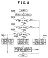
- Fig. 8 is a flow chart of a vehicle braking control routine to be executed in the motor-driven vehicle 11.
- the motor-driven vehicle 11 includes basically the same elements as those of the motor-driven vehicle 10 of the first embodiment and further includes a secondary battery 28, a fourth relay 34, and a SOC sensor 45 for detecting the charged state of the secondary battery 28. Therefore, the same elements as those of the motor-driven vehicle 10 will be denoted with the same numerals and characters and description thereof will be omitted.
- the fuel cell system 20 is used as a main power supply
- the secondary battery 28 is used as a secondary power supply which is operated when a sufficient level of power can not be supplied from the fuel cell system 20, such as before the operating state of the fuel cell system 20 becomes stable.
- the secondary battery 28 also serves as a secondary power supply of the ECU 40 and other electrical components.
- the secondary battery 28 is arranged to store the electric power that is generated while the drive motor 21 is used for applying the brake on the vehicle, thus enabling a regenerative braking operation in the motor-driven vehicle 11. Meanwhile, the power supply is switched between the fuel cell system 20 and the secondary battery 28 on the basis of a voltage control by a DC-DC converter (not shown).
- this routine needs to be performed appropriately when the vehicle required power is reduced (i.e., when a requirement for applying the brake on the vehicle is made), it is repeatedly executed at predetermined time intervals.
- the ECU 40 first detects the accelerator opening ⁇ acc via the accelerator opening sensor 41 and the vehicle speed Vc via the speed sensor 42 (step S200).
- the ECU 40 determines whether a charged capacity Bs of the secondary battery 28 detected by the SOC sensor 45 is equal to or larger than a reference charged capacity Bref (step S222). Namely, whether the secondary battery 28 is sufficiently charged is determined in this step.
- the ECU 40 closes the third and fourth relays 33, 34 while opening the first and second relays 31, 32 (step S224), thereby enabling the electric power generated by the drive motor 21 to be charged in the secondary battery 28, after which the routine ends.
- step S222 When the charged capacity Bs is equal to or larger than the reference charged capacity Bref (step S222: YES), conversely, the ECU 40 closes the second and third relays 32, 33 while opening the first and fourth relays 31, 34 (step S230), and the ECU 40 then sets the variable resistance value Rv (step S240), after which the routine ends. Accordingly, the drive motor 21 operates as a power generation braking device and the electric power generated by the drive motor 21 is consumed by the variable resistor 25.
- step S210 or S220 When “NO” is obtained in the step S210 or S220, conversely, the ECU 40 implements the step S250, after which the routine ends.
- the drive motor 21 operates as a regenerative braking device when the charged capacity of the secondary battery 28 detected by the SOC sensor 45 is not sufficient. According to the second embodiment, therefore, a portion of the power that has been consumed by the drive motor 21 can be regained at the time of decelerating the vehicle or applying the brake on the vehicle, which results in improved energy efficiency of the vehicle 11.
- the drive motor 21 can be used for applying the brake on the vehicle by operating it as a power generation braking device and the amount of load to be applied on the mechanical braking system can thereby be reduced as described in the first embodiment. Further, whether the drive motor 21 is either operated as a regenerative braking device or power generation braking device, a braking force can be obtained as needed by applying an electric brake, which leads to an improved drivability of the motor-driven vehicle 11 especially for decelerating and braking operation thereof.
- the drive motor 21 is used for applying the brake on the vehicle when the accelerator opening ⁇ acc is equal to or smaller than the reference accelerator opening ⁇ ref and the vehicle speed Vc is equal to or higher than the reference vehicle speed Vref.
- the drive motor 21 may be used for applying the brake on the vehicle, for example, when the accelerator opening ⁇ acc is zero (i.e., when the accelerator pedal 23 is released).
- the drive motor may be used for applying the brake on the vehicle when a reduction in the accelerator opening ⁇ acc per unit of time becomes equal to or larger than a predetermined value.
- the motor-driven vehicle 11 includes the fuel cell system 20 and secondary battery 28, it may include only the secondary battery 28 as its main power supply. Also in this case, even when the drive motor 21 can not be operated as a regenerative braking device, the vehicle braking operation using an electric brake can be continued by operating the drive motor 21 as a power generation braking device, whereby a desired braking ability can be achieved without enforcing the mechanical braking system. Also, in the first embodiment, the secondary battery 28 may be used in place of the fuel cell system 20. In this case, the warming-up operation of the fuel cell system 20 can be omitted.
- the vehicle braking operation by the drive motor 21 is mainly performed in accordance with the operation of the accelerator pedal 23 in the above-described embodiments, it may certainly be performed also when a brake pedal is depressed.
- variable resistor 25 is used as power consuming means in the above-described embodiments, a resistor having a constant resistance value may be used instead.
- the electric power generated by the drive motor 21 may be consumed by operating electric auxiliaries such as an air-blower for sending air to the fuel cell system 20 and a compressor of an air-conditioning system.
- an excessive amount of air which may be supplied from the air blower can be adjusted to an appropriate amount by releasing it to the outside, for example.
- the motor-driven vehicle includes a compressor which is mechanically driven by a drive shaft, or the like
- braking force may also be obtained when engaging the compressor with the drive motor 21. That is, in this case, a braking force can be obtained by applying a mechanical friction, as well as applying an electric resistance.
- the map for determining the variable resistance value Rv in the above-described embodiments is just one example. That is, the map may be such that the resistance value linearly changes with respect to the accelerator opening ⁇ acc, fuel cell temperature Tfc and so on.
- resistance value detecting portion may be provided in order to achieve further accuracy in changing the resistance value.
Landscapes
- Engineering & Computer Science (AREA)
- Life Sciences & Earth Sciences (AREA)
- Sustainable Development (AREA)
- Sustainable Energy (AREA)
- Power Engineering (AREA)
- Transportation (AREA)
- Mechanical Engineering (AREA)
- Electric Propulsion And Braking For Vehicles (AREA)
- Fuel Cell (AREA)
Abstract
An ECU closes a second relay and third relay while opening a first relay so that a drive motor and a variable resistor are connected in series, when it is determined based on detected accelerator opening θacc and vehicle speed Vc that a requirement for applying the brake on the vehicle has been made. The drive motor is driven by an external force which is input via wheels of the vehicle, thus operating as a power generation braking device. The ECU sets a variable resistance value Vc based on the accelerator opening θacc and the vehicle speed Vc. Thus, the electric power generated by the drive motor is consumed via an inverter by the variable resistor whose resistance value Rv has been set to a certain value. Accordingly, the amount of load to be applied on a mechanical braking system of a motor-driven vehicle can be reduced and an improved drivability in decelerating the vehicle can be achieved. <IMAGE>
Description
The present invention relates to a motor-driven vehicle which uses a
motor as its driving force source, and to a control method thereof.
Generally, in a vehicle including an internal combustion engine as its
driving force source (will hereinafter be referred to as "an engine-driven vehicle"), a
fine control of the vehicle speed can be easily performed by reducing a depression
amount of an accelerator pedal, namely by applying a so-called engine brake, which
originates from a friction loss, pumping loss, and the like, in the internal combustion
engine. In particular, such an engine brake is effectively used for decelerating the
vehicle speed in a relatively high vehicle speed range, whereby the amount of load
which may otherwise be applied on a mechanical braking system of the vehicle can be
reduced.
In the meantime, in the case of a vehicle including only a motor as its
driving force source (will hereinafter be referred to as "a motor-driven vehicle"), even
when the depression amount of the accelerator pedal is reduced, the motor that
generally has a small friction loss as compared to an internal combustion engine
continues to rotate due to an inertial force, thus generating driving force. With such a
motor-driven vehicle, it is therefore difficult to obtain an adequate braking force such
as that obtained by applying an engine brake as described above. Accordingly, as
compared to engine-driven vehicles, motor-driven vehicles involve a problem related
to the poor vehicle drivability attributed to the difficulty in adjusting the vehicle speed
by the accelerator pedal.
In motor-driven vehicles, moreover, since an adequate braking force
can only be obtained using a mechanical braking system, the mechanical braking
system is therefore operated under a large load as compared to mechanical braking
systems of engine-driven vehicles. In the case of motor-driven vehicles, therefore, it
is generally necessary to enforce the mechanical braking systems. To counter this
problem, in some motor-driven vehicles, a regenerative brake is also used for
applying the brake on the vehicle. This does not eliminate, however, the necessity for
enforcing mechanical braking systems in a motor-driven vehicle, since the
regenerative brake can no longer be used when a secondary battery has been charged
to its full capacity.
In view of the above problems, it is an object of the present invention
to reduce the amount of load on a mechanical braking system and improve the vehicle
drivability for deceleration in motor-driven vehicles. It is another object of the
invention to reduce the amount of load on a mechanical braking system and achieve
an earlier completion of a warming-up operation of a fuel cell system in motor-driven
vehicles which uses the fuel cell system as a power supply.
To achieve the above objects, a vehicle according to a first aspect of
the invention includes a motor for outputting a vehicle required power to the vehicle,
fuel cell system for generating an electric power, temperature detecting means for
detecting the temperature of the fuel cell system, electric power consuming means for
consuming an electric power, and switching device control means. The switching
device is arranged to selectively switch a connection state among a first connection
state wherein the fuel cell system and the electric power consuming means are
connected, second connection state wherein the motor and the electric power
consuming means are connected, and third connection state wherein the fuel cell
system and the motor are connected. The switching device control means is adapted
to control the switching device so as to establish the first connection state when the
temperature of the fuel cell system detected by the temperature detecting means is
equal to or lower than a predetermined temperature.
In the vehicle constructed as described above, the electric power
consuming means is selectively connected to either one of the fuel cell system and
motor. Thus, the warming-up operation of the fuel cell system can be accelerated and
the drive motor can be used as a power generation braking device for applying the
brake on the vehicle. That is, when the temperature of the fuel cell system is equal to
or lower than the predetermined temperature, the electric power consuming means is
connected to the fuel cell system so that the fuel cell system is operated under a high
load, thus accelerating the warming-up operation thereof.
In the vehicle according to the first aspect of the invention, it is
preferable that the electric power consuming means is a variable resistor whose
resistance value increases as the temperature detected by the temperature detecting
means reduces below the predetermined temperature. In this case, an appropriate
amount of load can be applied on the fuel cell system in accordance with its
temperature, whereby the time required for completing the warming-up operation of
the fuel cell system can be reduced regardless of its temperature.
Also, it is preferable that the vehicle according to the first aspect
invention further includes a reduction detecting means for detecting a reduction in the
vehicle required power, a motor control means is adapted to operate the motor as a
braking means for applying the brake on the vehicle when a reduction in the vehicle
required power is detected, and the switching device control means is adapted to
control the switching device so as to establish the second connection state when a
reduction in the vehicle required power is detected. With this arrangement, the
amount of load to be applied on the mechanical braking system can be reduced by
using the motor as the braking means. Also, the electric power that is generated by
the motor while it is operating as the braking means is consumed by the electric
power consuming means. Thus, the motor can be used as needed for applying the
brake on the vehicle even when power regeneration is not allowed, which results in an
improved drivability of the motor-driven vehicle.
Also, it is preferable that the vehicle according to the first aspect of
the invention further includes an accelerator pedal for inputting the vehicle required
power and vehicle speed detecting means for detecting a vehicle speed of the vehicle,
and the reduction detecting means is adapted to detect a reduction in the vehicle
required power when the depression amount of the accelerator pedal is equal to or
smaller than a predetermined value and the vehicle speed detected by the vehicle
speed detecting means is equal to or higher than a predetermined value. Accordingly,
further accuracy is achieved in detecting a reduction in the vehicle required power.
In the vehicle according to the first aspect of the invention, it is
preferable that the electric power consuming means is a variable resistor whose
resistance value increases as the depression amount of the accelerator pedal reduces
below the predetermined value. In this case, an electric power can be appropriately
consumed in accordance with the degree of reduction in the vehicle required power.
Also, it is preferable that the vehicle according to the first aspect of
the invention further includes a reduction detecting means for detecting a reduction in
the vehicle required power and the switching device control means is adapted to
control the switching device so as to establish the third connection state when a
reduction in the vehicle required power is not detected and the detected temperature
of the fuel cell system is higher than the predetermined temperature. In this case, the
motor-driven vehicle operates in a normal operating state.
A vehicle according to a second aspect of the invention includes a
motor for outputting a vehicle required power to the vehicle, power supply for
supplying a power to the motor, reduction detecting means for detecting a reduction in
the vehicle required power, motor control means, electric power consuming means,
switching device, and switching device control means. The motor control means is
adapted to operate the motor as a braking means for applying the brake on the vehicle
when a reduction in the vehicle required power is detected. The electric power
consuming means is arranged to consume the electric power that is generated by the
motor while it is operating as the braking means. The switching device is arranged to
selectively switch a connection state between a first connection state wherein the
motor and the electric power consuming means are connected and a second
connection state wherein the power supply and the motor are connected. The
switching device control means is adapted to control the switching device so as to
establish the first connection state when the reduction detecting means detects a
reduction in the vehicle required power.
With the vehicle constructed as described above, the amount of load
to be applied on the mechanical braking system can be reduced by using the motor as
the braking means when a reduction in the vehicle required power is detected. Also,
since the electric power that is generated by the motor while it is operating as the
braking means is consumed by the electric power consuming means, the motor can be
used for applying the brake on the vehicle even when a power regeneration is not
allowed. Accordingly, the drivability of the motor-driven vehicle can be improved.
It is preferable that the vehicle according to the second aspect of the
invention further includes an accelerator pedal for inputting the vehicle required
power and the reduction detecting means is adapted to detect a reduction in the
vehicle required power when the depression mount of the accelerator pedal changes to
a smaller value. In this case, a reduction in the vehicle-required power is detected on
the basis of the operation of the accelerator pedal, whereby the motor-driven vehicle
can have as a good drivability as that of an engine-driven vehicle.
In the vehicle according to the second aspect of the invention, it is
preferable that the electric power consuming means is a variable resistor whose
resistance value increases as the depression amount of the accelerator pedal reduces or
a motor for driving an auxiliary, which motor is driven when a reduction in the
vehicle required power is detected. Whether the electric power consuming means is
such a variable resistor or motor, the electric power consuming means acts as a load
on the motor when it is operating as a power generator. Thus, the rotation speed of
the motor is reduced and a braking force is thereby generated.
Also, it is preferable that the vehicle according to the second aspect
of the invention further includes an accelerator pedal for inputting the vehicle required
power and vehicle speed detecting means for detecting the vehicle speed of the
vehicle, and the reduction detecting means is adapted to detect a reduction in the
vehicle required power when the depression amount of the accelerator pedal is equal
to or smaller than a predetermined value and the vehicle speed detected by the vehicle
speed detecting means is equal to or higher than a predetermined value. In this case,
further accuracy can be achieved in detecting a reduction in the vehicle required
power.
In the vehicle according to the second aspect of the invention, it is
also preferable that the power supply is a fuel cell system or consists of a fuel cell
system and secondary battery. In the former case, the vehicles uses only the fuel cell
system as the power supply. In the latter case, the vehicle uses the fuel cell system
and secondary battery as the power supply.
A vehicle according to a third aspect of the invention includes a motor
for outputting a vehicle required power to the vehicle, secondary battery for charging
and discharging an electric power, electric power consuming means for consuming an
electric power, switching device, reduction detecting means for detecting a reduction
in the vehicle required power, the motor control means is adapted to operate the motor
as a braking means for applying the brake on the vehicle when a reduction in the
vehicle required power is detected, and switching device control means. The
switching device is arranged to selectively switch a connection state between a first
connection state wherein the motor and the electric power consuming means are
connected and a second connection state wherein the secondary battery and the motor
are connected. The switching device control means is adapted to control the
switching device so as to establish the first connection state when a reduction in the
vehicle required power is detected and the charged capacity of the secondary battery
is equal to or larger than a predetermined value.
In the vehicle constructed as described above, the electric power
consuming means begins to consume the power that is generated by the motor
operating as the braking means when a reduction in the vehicle required power is
detected while the charged capacity of the secondary battery is equal to or larger than
the predetermined value. With this arrangement, the motor can be used for applying
the brake on the vehicle and the amount of load to be applied on the mechanical
braking system can be thereby reduced even when a power regeneration is not
allowed. Also, when the electric power is thus consumed by the electric power
consuming means, it reduces the rotation speed of the motor, whereby the drivability
of the motor-driven vehicle can be improved.
In the vehicle according to the third aspect of the invention, it is
preferable that the switching device control means is adapted to control the switching
device so as to establish the second connection state when a reduction in the vehicle
required power is detected and the charged capacity of the secondary battery is
smaller than the predetermined value. In this case, a means of the power that has been
consumed by the motor can be regained, which results in an improved energy
efficiency of the vehicle.
Also, it is preferable that the vehicle according to the third aspect of
the invention further includes a fuel cell system as a main power supply and the
switching device is arranged to selectively switch a connection state among the first
connection state, the second connection state, and a third connection state wherein the
fuel cell system and the motor are connected, and the switching device control means
is adapted to control the switching device so as to establish the third connection state
when a reduction in the vehicle required power is not detected. With this
arrangement, the motor can operate using the power supplied from the fuel cell
system and a means of the power which has been consumed by the motor can be
regained and charged in the secondary battery.
A braking control method according to a forth aspect of the invention
is used in a vehicle including a motor for outputting a vehicle required power, fuel
cell system for generating an electric power, temperature detecting means for
detecting the temperature of the fuel cell system, and electric power consuming means
for consuming an electric power. The braking control method includes detecting a
temperature of the fuel cell system by means of the temperature detecting means,
determining whether the temperature of the fuel cell system is equal to or lower than a
predetermined temperature, and establishing a first connection state selected from the
first connection state wherein the fuel cell system and the electric power consuming
means are connected, a second connection state wherein the motor and the electric
power consuming means are connected, and a third connection state wherein the fuel
cell system and the motor are connected, when the temperature of the fuel cell system
is equal to or lower than the predetermined temperature. According to this method,
the electric power consuming means is selectively connected to either one of the fuel
cell system and the motor, whereby the warming-up operation of the fuel cell system
can be accelerated and the drive motor can be used as a power generation braking
device for applying the brake on the vehicle. That is, when the temperature of the fuel
cell system is equal to or lower than the predetermined temperature, the electric power
consuming means is connected to the fuel cell system so that the fuel cell system is
operated under a high load, thus accelerating the warming-up operation thereof.
A braking control method according to a fifth aspect of the invention
is used in a vehicle including a motor for outputting a vehicle required power to the
vehicle, a power supply for supplying a power to the motor, a reduction detecting
means for detecting a reduction in the vehicle required power, a motor control means
which operates the motor as a braking means for applying the brake on the vehicle
when a reduction in the vehicle required power is detected, and an electric power
consuming means for consuming an electric power generated by the motor being
operated as the braking means. The braking control method includes establishing a
first connection state selected from the first connection state wherein the motor and
the electric power consuming means are connected and a second connection state
wherein the power supply and the motor are connected when the reduction detecting
means detects a reduction in the vehicle required power. According to this method,
the amount of load to be applied on the mechanical braking system can be reduced by
using the motor as the braking means when a reduction in the vehicle required power
is detected. Also, since the electric power that is generated by the motor while it is
operating as the braking means is consumed by the electric power consuming means,
the motor can be used for applying the brake on the vehicle even when a power
regeneration is not allowed. Accordingly, the drivability of the motor-driven vehicle
can be improved.
A braking control method according to a sixth aspect of the invention
is used in a vehicle including a motor for outputting a vehicle required power to the
vehicle, secondary battery for charging and discharging an electric power, electric
power consuming means for consuming an electric power, reduction detecting means
for detecting a reduction in the vehicle required power, and a motor control means
which operates the motor as a braking means for applying the brake on the vehicle
when a reduction in the vehicle required power is detected. This braking control
method includes detecting the charged capacity of the secondary battery, determining
whether the charged capacity of the secondary battery is equal to or larger than a
predetermined value, and establishing a first connection state selected from the first
connection state wherein the motor and the electric power consuming means are
connected and a second connection state wherein the secondary battery and the motor
are connected, when a reduction in the vehicle required power is detected and the
charged capacity of the secondary battery is equal to or larger than the predetermined
value. According to this method, the amount of load to be applied on the mechanical
braking system can be reduced by using the motor as the braking means when a
reduction in the vehicle required power is detected. Also, since the electric power
generated by the motor operating as the braking means is consumed by the electric
power consuming means, the motor can be used for applying the brake on the vehicle
even when a power regeneration is not allowed. Thus, the drivability of the motor-driven
vehicle can be improved.
The foregoing and/or further objects, features and advantages of the invention
will become more apparent from the following description of preferred embodiments
with reference to the accompanying drawings, in which like numerals are used to
represent like elements and wherein:
Hereinafter, a motor-driven vehicle according to a first embodiment of the
invention will be described with reference to Fig. 1. Fig. 1 schematically shows the
construction of a motor-driven vehicle 10 which includes a fuel cell system 20, drive
motor 21, inverter 22, accelerator pedal 23, wheels 24, and variable resistor 25. The
fuel cell system 20 serves as a power supply of the motor-driven vehicle 10. The
drive motor 21 is operated to convert an electric power supplied from the power
supply into a driving force. The inverter 22 is adapted to control the operation of the
drive motor 21. The accelerator pedal 23 is used for inputting a vehicle required
power, a power required to be output to the vehicle 10. The wheels 24 are driven by
the drive motor 21. The resistance value of the variable resistor 25 can be
continuously changed.
The fuel cell system 20, inverter 22, and variable resistor 25 are
connected via power lines such that three different closed electric circuits can be
selectively established. More specifically, when the vehicle required power is
reduced (i.e., when a braking force is required), a first relay 31 is opened while
second and third relays 32, 33 are closed to establish a closed circuit in which the
inverter 22 and the variable resistor 25 are connected in series. Under the normal
operating state of the vehicle, the second relay 32 is opened while the first and third
relays 31, 33 are closed to establish a closed circuit in which the fuel cell system 20
and the inverter 22 are connected in series. When performing a warming-up operation
of the fuel cell system 20, the third relay 33 is opened while the first and second
relays 31, 32 are closed to establish a closed circuit in which the fuel cell system 20
and the variable resistor 25 are connected in series.
The motor-driven vehicle 10 is provided with an electronic control
unit (ECU) 40. The ECU 40 is arranged to control the operation of the fuel cell
system 20 and drive motor 21, the opening and closing operation of the relays 31, 32,
and 33, and the resistance value of the variable resistor 25. The ECU 40 includes a
central processing unit (CPU), recording mediums (RAM, ROM), and other
components, which are not shown in the figure.
The ECU 40 are connected via signal lines to various sensors for
detecting operation conditions of the motor-driven vehicle 10, such as an accelerator
opening sensor 41 that detects the depression amount of an accelerator pedal as
"accelerator opening ", vehicle speed sensor 42 which is disposed in the vicinity of
one of the wheels 24 for detecting the vehicle speed, and temperature sensor 43 for
detecting the temperature of the fuel cell system 20. The ECU 40 are also connected
via signal lines to the respective relays 31, 32, and 33, inverter 22, and variable
resistor 25.
The fuel cell system 20 is a battery system which generates an
electric power using a reformed gas which is produced by a reformer (not shown) and
includes hydrogen, or a hydrogen gas as a fuel. In the meantime, a fuel supply system
for supplying reformed gas, air, and the like is not shown in the figures.
The drive motor 21 is a three-phase synchronous motor including a
rotor provided with a plurality of permanent magnets disposed on its periphery, and a
stator wound with wires to form a three-phase coil. The rotor of the drive motor 21 is
connected via a gear mechanism, or the like, to the wheels 24. A driving force is
generated and output to the wheels 24 when the rotor is driven to rotate by mutual
reactions that occur between an electromagnetic field produced by each permanent
magnet of the rotor and that produced by the three-phase coil of the stator. In the
meantime, when a deceleration requirement (a braking requirement) is made, the
drive motor 21 begins to operate as a power generation braking device. At this time,
more specifically, the rotor of the drive motor 21 is driven by an external force and
the mutual reactions between the electromagnetic fields are thereby caused so that
electromotive forces are generated at respective ends of the three-phase coil.
Next, a warming-up operation of the fuel cell system 20 which is
performed in the motor-driven vehicle 10 of the first embodiment will be described
with reference to Figs. 2 and 3. Fig. 2 is a flowchart of a control routine that is
executed when performing the warming-up operation of the fuel cell system 20, and
Fig. 3 shows one example of a map used for determining the resistance value of the
variable resistor 25 during the warming-up operation of the fuel cell system 20.
This control routine begins, for example, when a requirement for
starting the operation of the motor-driven vehicle 10 is made. Here, it is to be noted
that the relays 31, 32, and 33 are all open before beginning this routine. The ECU 40
first detects a temperature Tfc of the fuel cell system 20 via the temperature sensor 43
(step S100), and then determines whether the detected temperature Tfc is equal to or
lower than a reference temperature Tref (step S110). Here, if the reference
temperature Tref is set to 0 °C, for example, whether the water produced during the
operation of the fuel cell system 20 (will hereinafter be described as "the resultant
water") can be frozen is determined in this step. When the temperature Tfc is higher
than the reference temperature Tref (step S110: NO), it means that the resultant water
can not be frozen, and the ECU 40 therefore closes the first and third relays 31, 33
while opening the second relay 32 (step S140), after which the routine ends.
When the temperature Tfc is equal to or lower than the reference
temperature Tref (step S110: YES), conversely, the ECU 40 closes the first and
second relays 31, 32 and opens the third relay 33 so that the fuel cell system 20 and
variable resistor 25 are connected in series (step S120). Subsequently, the ECU 40
determines a variable resistance value Rv of the variable resistor 25 in accordance
with the detected temperature Tfc of the fuel cell system 20 using a map as shown in
Fig. 3, and sets the resistance value of the variable resistor 25 to the determined
variable resistance value Rv (step S130), after which the ECU 40 returns to the step
S110. Thus, these steps S120 to S130 are repeated until the ECU 40 determines that
the temperature Tfc of the fuel cell system 20 is higher than the reference temperature
Tref, namely until the warming-up operation of the fuel cell system 20 has been
completed.
In the map of Fig. 3, a horizontal axis represents the temperature Tfc
of the fuel cell system 20 while a vertical axis represents the variable resistance value
Rv. As shown in Fig. 3, the variable resistance value Rv increases as the detected
temperature Tfc reduces. When the temperature Tfc is low, therefore, the fuel cell
system 20 is operated under a high load so that the reactions in the fuel cell system 20
are accelerated and the time required for completing the warming-up operation is
thereby reduced. By thus warming up the fuel cell system 20, freezing of the resultant
water, which may occur when starting up the fuel cell system 20 under low
temperature, can be prevented.
Next, a vehicle braking control procedure which is performed in the
motor-driven vehicle 10 of the first embodiment will be described with reference to
Figs. 4 to 6. Fig. 4 is a flowchart of a vehicle braking control routine executed in the
motor-driven vehicle of the first embodiment. Fig. 5 shows one example of a map
used for determining a basic resistance value in accordance with an accelerator
opening acc, while Fig. 6 shows one example of a map used for determining a
correction value corresponding to the basic resistance value in accordance with a
vehicle speed Vc. These values are determined when implementing a braking process
of the routine.
Since this braking control routine needs to be executed appropriately
when the vehicle required power is reduced (i.e., when a requirement for decelerating
the vehicle or applying the brake on the vehicle is made), it is repeatedly executed at
predetermined time intervals. When the routine begins, the ECU 40 first detects the
accelerator opening acc via the accelerator opening sensor 41 and detects the
vehicle speed Vc via the speed sensor 42 (step S200).
The ECU 40 then determines whether the detected accelerator
opening acc is equal to or smaller than a reference accelerator opening ref (step
S210). When the detected accelerator opening acc is equal to or smaller than the
reference accelerator opening ref (step S210: YES), the ECU 40 then determines
whether the detected vehicle speed Vc is equal to or higher than a reference vehicle
speed Vref (step S220).
When the vehicle speed Vc is equal to or higher than the reference
vehicle speed Vref (step S220: YES), the ECU 40 closes the second and third relays
32, 33 while opening the first relay 31 (step S230) so that the drive motor 21 and
variable resistor 25 are connected in series in the circuit for applying the brake on the
vehicle. In this state where the electric connection between the fuel cell system 20 as
a power supply and the drive motor 21 (inverter 22) is shut off, the drive motor 21 is
driven by an external force that is input via the wheels 24, thus operating the motor 21
as a power generation braking device. That is, when the vehicle speed Vc is in a high
speed range while the accelerator opening acc is small, it is generally assumed that a
deceleration requirement (a braking requirement) is being made by operating the
accelerator pedal 23, and the motor 21 is therefore used for applying the brake on the
vehicle.
Subsequently, the ECU 40 determines a basic variable resistance
value Rvb in accordance with the detected accelerator opening acc using a map as
shown in Fig. 5, and the ECU 40 thereafter determines a correction value for
correcting the basic variable resistance value Rvb in accordance with the detected
vehicle speed Vc using a map as shown in Fig. 6. The ECU 40 then determines a
variable resistance value Rv by multiplying the basic variable resistance value Rvb
with the correction value (step S240), and sets the resistance value of the variable
resistor 25 to the determined variable resistance value Rv, after which the routine
ends.
In this state where the current generated by the drive motor 21 is
applied via the inverter 22 to the variable resistor 25, the electric power converted
from a mechanical power (a driving force) by the drive motor 21 is consumed as a
thermal energy at the variable resistor 25. Thus, the drive motor 21 can be used as
needed for applying the brake on the vehicle without being put into "power
regeneration impossible condition", which is a problem when the drive motor 21 is
used as a regenerative motor.
Further, when the drive motor 21 is connected to an external
resistance as described above, the current reduces and the rotation speed of the rotor
of the drive motor 21 thereby reduces. By thus limiting the inertial motion of the
drive motor 21, it is possible to generate an equivalent braking force to that obtained
when applying an engine brake in an internal combustion engine. Also, as is apparent
from Figs. 5 and 6, the variable resistance Rv of the variable resistor 25 is set to a
higher value as the required braking force increases. Therefore, the rotation of the
rotor of the drive motor 21 can be effectively limited.
On the other hand, when the accelerator opening acc is larger than
the reference accelerator opening ref (step S210: NO) and the detected vehicle
speed Vc is lower than the reference vehicle speed Vref (step S220: NO), the ECU 40
closes the first and third relays 31, 33 while opening the second relay 32 so that the
fuel cell system 20 and drive motor 21 are connected (step S250), after which the
routine ends. In this case, since it is unnecessary to use the drive motor 21 for
applying the brake on the vehicle, the relays 31, 32, and 33 are respectively switched
ac required for allowing the normal operating state of the vehicle.
According to the first embodiment of the invention, as described
above, by using one variable resistance 25, it becomes possible to accelerate the
warming-up operation of the fuel cell system 20 and to apply an electric brake to the
motor-driven vehicle 10. Also, as a result of using the variable resistor 25 for
accelerating the warming-up operation of the fuel cell system 20 as described above,
freezing of the resultant water, which may occur when the temperature Tfc of the fuel
cell system 20 is low, can be prevented.
In the first embodiment, as described above, the electric power
generated by the drive motor 21 at the time of decelerating the vehicle or applying the
brake on the vehicle is consumed by the variable resistor 25. Therefore, an electric
brake can be applied on the vehicle as needed even when a power regeneration is not
allowed. In the motor-driven vehicle 10, therefore, the amount of load to be applied
on the mechanical braking system is reduced, whereby an equivalent braking force to
that obtained in an engine-driven vehicle can be obtained without enforcing the
mechanical braking system.
Also, since the rotation of the rotor of the drive motor 21 is limited
by connecting the drive motor 21 to the variable resistor 25, a similar brake feeling to
that of an engine brake in engine-driven vehicles can be obtained, which improves the
drivability of motor-driven vehicles.
Hereinafter, a motor-driven vehicle according to a second embodiment of the
invention will be described with reference to Figs. 7 and 8. Fig. 7 schematically
shows the construction of a motor-driven vehicle 11 of the second embodiment. Fig.
8 is a flow chart of a vehicle braking control routine to be executed in the motor-driven
vehicle 11.
The motor-driven vehicle 11 includes basically the same elements as
those of the motor-driven vehicle 10 of the first embodiment and further includes a
secondary battery 28, a fourth relay 34, and a SOC sensor 45 for detecting the charged
state of the secondary battery 28. Therefore, the same elements as those of the motor-driven
vehicle 10 will be denoted with the same numerals and characters and
description thereof will be omitted.
In the second embodiment, the fuel cell system 20 is used as a main
power supply, and the secondary battery 28 is used as a secondary power supply
which is operated when a sufficient level of power can not be supplied from the fuel
cell system 20, such as before the operating state of the fuel cell system 20 becomes
stable. The secondary battery 28 also serves as a secondary power supply of the ECU
40 and other electrical components. The secondary battery 28 is arranged to store the
electric power that is generated while the drive motor 21 is used for applying the
brake on the vehicle, thus enabling a regenerative braking operation in the motor-driven
vehicle 11. Meanwhile, the power supply is switched between the fuel cell
system 20 and the secondary battery 28 on the basis of a voltage control by a DC-DC
converter (not shown).
Next, a vehicle braking control procedure executed in the motor-driven
vehicle 11 having a foregoing construction will be described with reference to
Fig. 8. Note that the same steps as those of the vehicle braking control routine in the
first embodiment will be denoted with the same numerals and description thereof will
be omitted.
Since this routine needs to be performed appropriately when the
vehicle required power is reduced (i.e., when a requirement for applying the brake on
the vehicle is made), it is repeatedly executed at predetermined time intervals. When
the routine begins, the ECU 40 first detects the accelerator opening acc via the
accelerator opening sensor 41 and the vehicle speed Vc via the speed sensor 42 (step
S200).
When "YES" is obtained both in the steps S210 and S220, the ECU
40 then determines whether a charged capacity Bs of the secondary battery 28
detected by the SOC sensor 45 is equal to or larger than a reference charged capacity
Bref (step S222). Namely, whether the secondary battery 28 is sufficiently charged is
determined in this step. When the charged capacity Bs is smaller than the reference
charged capacity Bref (step S222: NO), the ECU 40 closes the third and fourth relays
33, 34 while opening the first and second relays 31, 32 (step S224), thereby enabling
the electric power generated by the drive motor 21 to be charged in the secondary
battery 28, after which the routine ends.
When the charged capacity Bs is equal to or larger than the reference
charged capacity Bref (step S222: YES), conversely, the ECU 40 closes the second
and third relays 32, 33 while opening the first and fourth relays 31, 34 (step S230),
and the ECU 40 then sets the variable resistance value Rv (step S240), after which the
routine ends. Accordingly, the drive motor 21 operates as a power generation braking
device and the electric power generated by the drive motor 21 is consumed by the
variable resistor 25.
When "NO" is obtained in the step S210 or S220, conversely, the
ECU 40 implements the step S250, after which the routine ends.
As described above, in the motor-driven vehicle 11 of the second
embodiment which includes the secondary battery 28 as a secondary power supply,
the drive motor 21 operates as a regenerative braking device when the charged
capacity of the secondary battery 28 detected by the SOC sensor 45 is not sufficient.
According to the second embodiment, therefore, a portion of the power that has been
consumed by the drive motor 21 can be regained at the time of decelerating the
vehicle or applying the brake on the vehicle, which results in improved energy
efficiency of the vehicle 11.
In the second embodiment, too, even when the charged capacity of
the secondary battery 28 detected by the SOC sensor 45 is sufficient, the drive motor
21 can be used for applying the brake on the vehicle by operating it as a power
generation braking device and the amount of load to be applied on the mechanical
braking system can thereby be reduced as described in the first embodiment. Further,
whether the drive motor 21 is either operated as a regenerative braking device or
power generation braking device, a braking force can be obtained as needed by
applying an electric brake, which leads to an improved drivability of the motor-driven
vehicle 11 especially for decelerating and braking operation thereof.
While the invention has been described with reference to the
preferred embodiments thereof, it is to be understood that the preferred embodiments
are provided for the purpose of facilitating understanding of the invention but do not
put any limit to the invention. To the contrary, the invention is intended to cover
various modifications and equivalent arrangements within the spirit and scope of the
invention.
In the first embodiment, the drive motor 21 is used for applying the
brake on the vehicle when the accelerator opening acc is equal to or smaller than the
reference accelerator opening ref and the vehicle speed Vc is equal to or higher than
the reference vehicle speed Vref. Alternatively, the drive motor 21 may used for
applying the brake on the vehicle, for example, when the accelerator opening acc is
zero (i.e., when the accelerator pedal 23 is released). Also, by monitoring changes in
the accelerator opening acc with time, the drive motor may be used for applying the
brake on the vehicle when a reduction in the accelerator opening acc per unit of time
becomes equal to or larger than a predetermined value.
With regard to the second embodiment, while the motor-driven
vehicle 11 includes the fuel cell system 20 and secondary battery 28, it may include
only the secondary battery 28 as its main power supply. Also in this case, even when
the drive motor 21 can not be operated as a regenerative braking device, the vehicle
braking operation using an electric brake can be continued by operating the drive
motor 21 as a power generation braking device, whereby a desired braking ability can
be achieved without enforcing the mechanical braking system. Also, in the first
embodiment, the secondary battery 28 may be used in place of the fuel cell system 20.
In this case, the warming-up operation of the fuel cell system 20 can be omitted.
Also, while the vehicle braking operation by the drive motor 21 is
mainly performed in accordance with the operation of the accelerator pedal 23 in the
above-described embodiments, it may certainly be performed also when a brake pedal
is depressed.
Also, while the variable resistor 25 is used as power consuming
means in the above-described embodiments, a resistor having a constant resistance
value may be used instead. Alternatively, the electric power generated by the drive
motor 21 may be consumed by operating electric auxiliaries such as an air-blower for
sending air to the fuel cell system 20 and a compressor of an air-conditioning system.
When the power is thus consumed by the air-blower, an excessive amount of air
which may be supplied from the air blower can be adjusted to an appropriate amount
by releasing it to the outside, for example. Also, when the motor-driven vehicle
includes a compressor which is mechanically driven by a drive shaft, or the like,
braking force may also be obtained when engaging the compressor with the drive
motor 21. That is, in this case, a braking force can be obtained by applying a
mechanical friction, as well as applying an electric resistance.
Further, the map for determining the variable resistance value Rv in
the above-described embodiments is just one example. That is, the map may be such
that the resistance value linearly changes with respect to the accelerator opening
acc, fuel cell temperature Tfc and so on.
Also, while no means for detecting the resistance value of the
variable resistor 25 is provided in the above-described embodiments, resistance value
detecting portion may be provided in order to achieve further accuracy in changing
the resistance value.
Claims (23)
- A vehicle (10) including a motor (21) for outputting a vehicle required power to the vehicle (10), a fuel cell system (20) for generating an electric power, temperature detecting means (43) for detecting a temperature of the fuel cell system (20), and electric power consuming means (25) for consuming an electric power, the vehicle being characterized by further comprising
a switching device (31, 32, 33) which selectively switches a connection state among a first connection state wherein the fuel cell system (20) and the electric power consuming means (25) are connected, a second connection state wherein the motor (21) and the electric power consuming means (25) are connected, and a third connection state wherein the fuel cell system (20) and the motor (21) are connected; and
switching device control means (40) which controls the switching device (31, 32, 33) to establish the first connection state when the temperature of the fuel cell system (20) detected by the temperature detecting means (43) is equal to or lower than a predetermined temperature. - The vehicle (10) according to claim 1, characterized in that
the electric power consuming means (25) comprises a variable resistor (25), a resistance value of which increases as the temperature detected by the temperature detecting means (43) reduces below the predetermined temperature. - The vehicle (10) according to claim 1, further comprising reduction detecting means (41) for detecting a reduction in the vehicle required power, and motor control means (22) which operates the motor (21) as braking means for applying the brake on the vehicle (10) when a reduction in the vehicle required power is detected, the vehicle (10) being characterized in that
the switching device control means (40) controls the switching device (31, 32, 33) to establish the second connection state when a reduction in the vehicle required power is detected. - The vehicle (10) according to any one of claims 3, further comprising an accelerator pedal (23) for inputting the vehicle required power; and
vehicle speed detecting means (42) for detecting a vehicle speed of the vehicle (10), the vehicle (10) being characterized in that
the reduction detecting means (41) detects a reduction in the vehicle required power when a depression amount of the accelerator pedal (23) is equal to or smaller than a predetermined value and the detected vehicle speed is equal to or higher than a predetermined value. - The vehicle (10) according to claim 4, characterized in that the electric power consuming means (25) comprises a variable resistor (25), a resistance value of which increases as the depression amount of the accelerator pedal (23) reduces below the predetermined value.
- The vehicle (10) according to any one of claims 1, further comprising reduction detecting means (41) for detecting a reduction in the vehicle required power, the vehicle (10) being characterized in that
the switching device control means (40) controls the switching device (31, 32, 33) to establish the third connection state when a reduction in the vehicle required power is not detected and the detected temperature of the fuel cell system (20) is higher than the predetermined temperature. - A vehicle (11) including a motor (21) for outputting a vehicle required power to the vehicle (11), a power supply (20) for supplying an electric power to the motor (21), reduction detecting means (41) for detecting a reduction in the vehicle required power, the vehicle (11) being characterized by further comprising
motor control means (22) which operates the motor (21) as braking means for applying the brake on the vehicle (11) when a reduction in the vehicle required power is detected;
electric power consuming means (25) for consuming an electric power generated by the motor (21) being operated as the braking means;
a switching device (31, 32, 33, 34) which selectively switches a connection state between a first connection state wherein the motor (21) and the electric power consuming means (25) are connected and a second connection state wherein the power supply (20) and the motor (21) are connected; and
switching device control means (40) which controls the switching device (31, 32, 33, 34) to establish the first connection state when the reduction detecting means (41) detects a reduction in the vehicle required power. - The vehicle (11) according to claim 7, further comprising an accelerator pedal (23) for inputting the vehicle required power, the vehicle (11) being characterized in that
the reduction detecting means (41) detects a reduction in the vehicle required power when a depression mount of the accelerator pedal (23) reduces. - The vehicle (11) according to claim 8, characterized in that
the electric power consuming means (25) comprises a variable resistor (25), a resistance value of which increases as the depression amount of the accelerator pedal (23) reduces. - The vehicle (11) according to claim 8, characterized in that
the electric power consuming means (25) comprises an motor (21) for driving an auxiliary, which motor (21) is driven when a reduction in the vehicle required power is detected. - The vehicle (11) according to claim 7, further comprising
an accelerator pedal (23) for inputting the vehicle required power; and
vehicle speed detecting means (11) for detecting a vehicle speed of the vehicle (11), the vehicle (11) being characterized in that
the reduction detecting means (41) detects a reduction in the vehicle required power when a depression amount of the accelerator pedal (23) is equal to or smaller than a predetermined value and the vehicle speed detected by the vehicle speed detecting means (42) is equal to or higher than a predetermined value. - The vehicle (11) according to claim 11, characterized in that the electric power consuming means (25) comprises a variable resistor (25), a resistance value of which increases as the depression amount of the accelerator pedal (23) reduces below the predetermined value.
- The vehicle (11) according to claim 7, characterized in that
the switching device control means (40) controls the switching device (31, 32, 33, 34) to establish the second connection state when a reduction in the vehicle required power is not detected. - The vehicle (11) according to any one of claims 7 to 13, characterized in that
the power supply (20) comprises a fuel cell system (20). - The vehicle (11) according to claim 14, characterized in that
the power supply (20, 28) further comprises a secondary battery (28). - A vehicle (11) including a motor (21) for outputting a vehicle required power to the vehicle, a secondary battery (28) for charging and discharging an electric power, and electric power consuming means (25) for consuming an electric power, the vehicle (11) being characterized by further comprising
a switching device (31, 32, 33, 34) which selectively switches a connection state between a first connection state wherein the motor (21) and the electric power consuming means (25) are connected and a second connection state wherein the secondary battery (28) and the motor (21) are connected;
reduction detecting means (41) for detecting a reduction in the vehicle required power;
motor control means (22) which operates the motor (21) as braking means for applying the brake on the vehicle (11) when a reduction in the vehicle required power is detected;and
switching device control means (40) which controls the switching device (31, 32, 33, 34) to establish the first connection state when a reduction in the vehicle required power is detected and a charged capacity of the secondary battery (28) is equal to or larger than a predetermined value. - The vehicle (11) according to claim 16, characterized in that
the switching device control means (40) controls the switching device (31, 32, 33, 34) to establish the second connection state when a reduction in the vehicle required power is detected and the charged capacity of the secondary battery (28) is smaller than the predetermined value. - The vehicle (11) according to claim 16 or 17, further comprising
a fuel cell system (20) used as a main power supply, the vehicle (11) being characterized in that the switching device (31, 32, 33, 34) selectively switches a connection state among the first connection state, the second connection state, and a third connection state wherein the fuel cell system (20) and the motor (21) are connected, and
the switching device control means (40) controls the switching device (31, 32, 33, 34) to establish the third connection state when a reduction in the vehicle required power is not detected. - The vehicle (11) according to any one of claims 16 to 18 further comprising
an accelerator pedal (23) for inputting the vehicle required power; and
vehicle speed detecting means (42) for detecting a vehicle speed of the vehicle (11), the vehicle (11) being characterized in that
the reduction detecting means (41) detects a reduction in the vehicle required power when a depression amount of the accelerator pedal (23) is equal to or smaller than a predetermined value and the detected vehicle speed is equal to or higher than a predetermined value. - The vehicle (11) according to claim 19, characterized in that
the electric power consuming means (25) comprises a variable resistor (25), a resistance value of which increases as the depression amount of the accelerator pedal (23) reduces below the predetermined value. - A braking control method for a vehicle (11) including a motor (21) for outputting a vehicle required power, a fuel cell system (20) for generating an electric power, a temperature detecting means (43) for detecting a temperature of the fuel cell system (20), and an electric power consuming means (25) for consuming an electric power, the braking control method characterized by comprising
detecting a temperature of the fuel cell system (20) by the temperature detecting means (43);
determining whether the temperature of the fuel cell system (20) is equal to or lower than a predetermined temperature; and
establishing a first connection state selected from the first connection state wherein the fuel cell system (20) and the electric power consuming means (25) are connected, a second connection state wherein the motor (21) and the electric power consuming means (25) are connected, and a third connection state wherein the fuel cell system (20) and the motor (21) are connected, when the temperature of the fuel cell system (20) is equal to or lower than the predetermined temperature. - A motor (21) for outputting a vehicle required power to the vehicle (11), a power supply for supplying a power to the motor (21), a reduction detecting means (41) for detecting a reduction in the vehicle required power, a motor control means (22) which operates the motor (21) as a braking portion for applying the brake on the vehicle (11) when a reduction in the vehicle required power is detected, and an electric power consuming means (25) for consuming an electric power generated by the motor (21) being operated as the braking portion, the braking control method characterized by comprising
establishing a first connection state selected from the first connection state wherein the motor (21) and the electric power consuming means (25) are connected and a second connection state wherein the power supply (20) and the motor (21) are connected when the reduction detecting means (41) detects a reduction in the vehicle required power. - A braking control method for a vehicle including a motor (21) for outputting a vehicle required power to the vehicle (11), a secondary battery (28) for charging and discharging an electric power, an electric power consuming means (25) for consuming an electric power, a reduction detecting means (41) for detecting a reduction in the vehicle required power, and a motor control portion which operates the motor as a braking portion for applying the brake on the vehicle when a reduction in the vehicle required power is detected, the braking control method characterized by comprising
detecting a charged capacity of the secondary battery;
determining whether the charged capacity of the secondary battery is equal to or larger than a predetermined value; and
establishing a first connection state selected from the first connection state wherein the motor and the electric power consuming portion are connected and a second connection state wherein the secondary battery and the motor are connected, when a reduction in the vehicle required power is detected and the charged capacity of the secondary battery is equal to or larger than the predetermined value.
Applications Claiming Priority (2)
| Application Number | Priority Date | Filing Date | Title |
|---|---|---|---|
| JP2001388851A JP2003189409A (en) | 2001-12-21 | 2001-12-21 | Motor mounted vehicle |
| JP2001388851 | 2001-12-21 |
Publications (1)
| Publication Number | Publication Date |
|---|---|
| EP1321330A2 true EP1321330A2 (en) | 2003-06-25 |
Family
ID=19188213
Family Applications (1)
| Application Number | Title | Priority Date | Filing Date |
|---|---|---|---|
| EP02028509A Withdrawn EP1321330A2 (en) | 2001-12-21 | 2002-12-19 | Motor-driven vehicle and control method thereof |
Country Status (3)
| Country | Link |
|---|---|
| US (1) | US20030116367A1 (en) |
| EP (1) | EP1321330A2 (en) |
| JP (1) | JP2003189409A (en) |
Cited By (3)
| Publication number | Priority date | Publication date | Assignee | Title |
|---|---|---|---|---|
| EP1588889A3 (en) * | 2004-04-21 | 2007-10-17 | Conception et Développement Michelin S.A. | Electric traction assembly for fuel cell vehicle having an electric resistor for heat dissipation |
| WO2008052695A1 (en) * | 2006-10-31 | 2008-05-08 | Knorr-Bremse Systeme für Schienenfahrzeuge GmbH | Drive and brake system of a rail vehicle, comprising a generator brake and an additional friction brake |
| US7383903B2 (en) | 2004-04-21 | 2008-06-10 | Conception Et Developpement Michelin S.A. | Electrical power train for a vehicle, comprising an electrical dissipation element cooled by cooling liquid |
Families Citing this family (15)
| Publication number | Priority date | Publication date | Assignee | Title |
|---|---|---|---|---|
| FR2847528B1 (en) * | 2002-11-27 | 2005-01-28 | Renault Sa | MOTOR VEHICLE COMPRISING MEANS FOR VARYING THE EXTREME ACTUAL POSITION OF THE ACCELERATION PEDAL |
| WO2004076254A1 (en) * | 2003-02-24 | 2004-09-10 | Bendix Commercial Vehicle Systems Llc | Electro-pneumatic latching valve system |
| US7237748B2 (en) * | 2003-12-15 | 2007-07-03 | Delos Aerospace, Llc | Landing gear method and apparatus for braking and maneuvering |
| US7354118B2 (en) * | 2005-02-25 | 2008-04-08 | Bendix Commercial Vehicle Systems, Inc. | Control valve system |
| GB0523069D0 (en) * | 2005-11-11 | 2005-12-21 | Airbus Uk Ltd | Aircraft braking system |
| US9073448B2 (en) * | 2007-05-07 | 2015-07-07 | General Electric Company | Method of operating propulsion system |
| KR20100013313A (en) * | 2007-05-21 | 2010-02-09 | 주식회사 씨티앤티 | Power conversion controlling method of fuel cell-battery hybrid-electric vehicle and control device |
| IT1398207B1 (en) * | 2010-02-16 | 2013-02-14 | Alenia Aeronautica Spa | BRAKE SYSTEM FOR AIRCRAFT TROLLEY. |
| JP2012025601A (en) * | 2010-07-21 | 2012-02-09 | Sharp Corp | Carbon dioxide separator and method for using the same |
| JP5840425B2 (en) * | 2011-08-31 | 2016-01-06 | 株式会社東芝 | Electric railway vehicle charging system |
| CN104192003A (en) * | 2014-07-28 | 2014-12-10 | 厦门纵横通电动车有限公司 | Anti-slip device for electric sightseeing vehicle |
| JP5895073B2 (en) * | 2015-02-02 | 2016-03-30 | 東芝燃料電池システム株式会社 | FUEL CELL POWER GENERATION SYSTEM AND METHOD FOR POWERING UP ELECTRIC HEATER IN FUEL CELL POWER GENERATION SYSTEM |
| CN109866621A (en) * | 2019-03-01 | 2019-06-11 | 安徽安凯汽车股份有限公司 | A kind of pure electric vehicle braking energy consumption recyclable device |
| DE102021206598A1 (en) | 2021-06-25 | 2022-12-29 | Robert Bosch Gesellschaft mit beschränkter Haftung | Device for dissipating braking energy |
| CN117325660B (en) * | 2023-11-01 | 2025-12-19 | 吉林大学 | Cooperative braking system of hub motor and small EMB and control method |
Family Cites Families (12)
| Publication number | Priority date | Publication date | Assignee | Title |
|---|---|---|---|---|
| DE2740438C2 (en) * | 1977-09-08 | 1983-09-01 | I.P.F. Gesellschaft für Verwertung von Patenten mbH, 8000 München | Electric motor drive vehicle |
| US4564798A (en) * | 1982-10-06 | 1986-01-14 | Escutcheon Associates | Battery performance control |
| JP3608017B2 (en) * | 1996-07-22 | 2005-01-05 | トヨタ自動車株式会社 | Power system |
| JP4049833B2 (en) * | 1996-07-26 | 2008-02-20 | トヨタ自動車株式会社 | Power supply device and electric vehicle |
| JP4372235B2 (en) * | 1996-08-29 | 2009-11-25 | トヨタ自動車株式会社 | Fuel cell system and electric vehicle |
| DE19810467C1 (en) * | 1998-03-11 | 1999-10-14 | Daimler Chrysler Ag | Hybrid drive concept for fuel cell vehicles |
| JP4253920B2 (en) * | 1999-05-06 | 2009-04-15 | 日産自動車株式会社 | Fuel cell vehicle power distribution control device |
| JP5140894B2 (en) * | 2000-05-15 | 2013-02-13 | トヨタ自動車株式会社 | Power supply using fuel cell and chargeable / dischargeable power storage unit |
| JP4967185B2 (en) * | 2000-10-24 | 2012-07-04 | トヨタ自動車株式会社 | Removal of precipitated carbon in the reformer |
| JP3598975B2 (en) * | 2001-01-19 | 2004-12-08 | 日産自動車株式会社 | Control device for fuel cell vehicle |
| JP3624841B2 (en) * | 2001-03-06 | 2005-03-02 | 日産自動車株式会社 | Vehicle control device |
| JP3659204B2 (en) * | 2001-08-30 | 2005-06-15 | 日産自動車株式会社 | Mobile fuel cell power plant |
-
2001
- 2001-12-21 JP JP2001388851A patent/JP2003189409A/en active Pending
-
2002
- 2002-12-16 US US10/319,613 patent/US20030116367A1/en not_active Abandoned
- 2002-12-19 EP EP02028509A patent/EP1321330A2/en not_active Withdrawn
Cited By (4)
| Publication number | Priority date | Publication date | Assignee | Title |
|---|---|---|---|---|
| EP1588889A3 (en) * | 2004-04-21 | 2007-10-17 | Conception et Développement Michelin S.A. | Electric traction assembly for fuel cell vehicle having an electric resistor for heat dissipation |
| US7383903B2 (en) | 2004-04-21 | 2008-06-10 | Conception Et Developpement Michelin S.A. | Electrical power train for a vehicle, comprising an electrical dissipation element cooled by cooling liquid |
| US7404461B2 (en) | 2004-04-21 | 2008-07-29 | Conception Et Developpement Michelin, S.A. | Electrical power train for a fuel cell vehicle, comprising an electrical dissipation element |
| WO2008052695A1 (en) * | 2006-10-31 | 2008-05-08 | Knorr-Bremse Systeme für Schienenfahrzeuge GmbH | Drive and brake system of a rail vehicle, comprising a generator brake and an additional friction brake |
Also Published As
| Publication number | Publication date |
|---|---|
| JP2003189409A (en) | 2003-07-04 |
| US20030116367A1 (en) | 2003-06-26 |
Similar Documents
| Publication | Publication Date | Title |
|---|---|---|
| EP1321330A2 (en) | Motor-driven vehicle and control method thereof | |
| CA2408785C (en) | Supply of electric power using fuel cell and chargeable/dischargeable storage | |
| US6920948B2 (en) | DC power supply using fuel cell | |
| US7436148B2 (en) | Method of determining voltage condition of fuel cell vehicle | |
| JP3868947B2 (en) | Regenerative braking system and regenerative braking method using air conditioning system of electric vehicle | |
| JP3842015B2 (en) | Idle control device for fuel cell vehicle | |
| KR100385193B1 (en) | Fuel cell system and electric car mounting it and starting control method for fuel cell system | |
| EP1983603B1 (en) | Cooling fan control device and method | |
| KR101143438B1 (en) | Vehicle power control device | |
| US6630810B2 (en) | Hybrid vehicle and control method therefor | |
| JP3180304B2 (en) | Power circuit of hybrid car | |
| JP2004056868A (en) | Idle control device for fuel cell vehicle | |
| JP2001357865A (en) | Startup control device for fuel cell vehicle | |
| US7380621B2 (en) | Hybrid system | |
| US20100009225A1 (en) | Fuel cell system and mobile body | |
| JP2005304179A (en) | Drive system and moving body equipped with the same | |
| JP2018133147A (en) | Fuel cell system | |
| JP2004312964A (en) | Electric vehicle and performance setting method | |
| US7315771B2 (en) | Control device for fuel cell vehicle | |
| JP4438231B2 (en) | FUEL CELL DEVICE AND CONTROL METHOD FOR FUEL CELL DEVICE | |
| JP3709789B2 (en) | Power control apparatus and power supply apparatus control method | |
| JPH04207908A (en) | Discharge controller for retarder | |
| US12565108B2 (en) | Electrified vehicle | |
| JP2011009133A (en) | Control device of fuel cell system | |
| JP2004213961A (en) | Fuel cell system and vehicle equipped with the same |
Legal Events
| Date | Code | Title | Description |
|---|---|---|---|
| PUAI | Public reference made under article 153(3) epc to a published international application that has entered the european phase |
Free format text: ORIGINAL CODE: 0009012 |
|
| 17P | Request for examination filed |
Effective date: 20030114 |
|
| AK | Designated contracting states |
Designated state(s): AT BE BG CH CY CZ DE DK EE ES FI FR GB GR IE IT LI LU MC NL PT SE SI SK TR |
|
| AX | Request for extension of the european patent |
Extension state: AL LT LV MK RO |
|
| STAA | Information on the status of an ep patent application or granted ep patent |
Free format text: STATUS: THE APPLICATION HAS BEEN WITHDRAWN |
|
| 18W | Application withdrawn |
Effective date: 20040920 |