EP1321305A2 - Method for making gemstones with a unique micro discrete indicia - Google Patents
Method for making gemstones with a unique micro discrete indicia Download PDFInfo
- Publication number
- EP1321305A2 EP1321305A2 EP02080196A EP02080196A EP1321305A2 EP 1321305 A2 EP1321305 A2 EP 1321305A2 EP 02080196 A EP02080196 A EP 02080196A EP 02080196 A EP02080196 A EP 02080196A EP 1321305 A2 EP1321305 A2 EP 1321305A2
- Authority
- EP
- European Patent Office
- Prior art keywords
- gemstone
- micro
- indicia
- discrete indicia
- discrete
- Prior art date
- Legal status (The legal status is an assumption and is not a legal conclusion. Google has not performed a legal analysis and makes no representation as to the accuracy of the status listed.)
- Withdrawn
Links
- 239000010437 gem Substances 0.000 title claims abstract description 107
- 229910001751 gemstone Inorganic materials 0.000 title claims abstract description 107
- 238000000034 method Methods 0.000 title claims abstract description 29
- 230000003287 optical effect Effects 0.000 description 15
- 239000010432 diamond Substances 0.000 description 13
- 229910003460 diamond Inorganic materials 0.000 description 10
- 239000000463 material Substances 0.000 description 9
- 239000000523 sample Substances 0.000 description 7
- 239000013307 optical fiber Substances 0.000 description 6
- 238000013519 translation Methods 0.000 description 6
- 238000013461 design Methods 0.000 description 5
- 238000007654 immersion Methods 0.000 description 5
- 239000007787 solid Substances 0.000 description 5
- 238000010521 absorption reaction Methods 0.000 description 4
- 230000008878 coupling Effects 0.000 description 4
- 238000010168 coupling process Methods 0.000 description 4
- 238000005859 coupling reaction Methods 0.000 description 4
- 230000000284 resting effect Effects 0.000 description 4
- 241000579895 Chlorostilbon Species 0.000 description 3
- 230000007547 defect Effects 0.000 description 3
- 229910052876 emerald Inorganic materials 0.000 description 3
- 239000010976 emerald Substances 0.000 description 3
- 238000005516 engineering process Methods 0.000 description 3
- 238000003384 imaging method Methods 0.000 description 3
- 238000012634 optical imaging Methods 0.000 description 3
- 238000005034 decoration Methods 0.000 description 2
- 239000000835 fiber Substances 0.000 description 2
- 230000003993 interaction Effects 0.000 description 2
- 238000005259 measurement Methods 0.000 description 2
- 230000007246 mechanism Effects 0.000 description 2
- 230000008569 process Effects 0.000 description 2
- 238000012552 review Methods 0.000 description 2
- 241000549343 Myadestes Species 0.000 description 1
- 238000002679 ablation Methods 0.000 description 1
- 239000011358 absorbing material Substances 0.000 description 1
- 230000009471 action Effects 0.000 description 1
- 238000013459 approach Methods 0.000 description 1
- 230000008859 change Effects 0.000 description 1
- 238000006243 chemical reaction Methods 0.000 description 1
- 239000011248 coating agent Substances 0.000 description 1
- 238000000576 coating method Methods 0.000 description 1
- 230000008021 deposition Effects 0.000 description 1
- 230000031700 light absorption Effects 0.000 description 1
- 238000004020 luminiscence type Methods 0.000 description 1
- 238000004519 manufacturing process Methods 0.000 description 1
- 229940074869 marquis Drugs 0.000 description 1
- 238000013017 mechanical damping Methods 0.000 description 1
- 238000005065 mining Methods 0.000 description 1
- 238000012986 modification Methods 0.000 description 1
- 230000004048 modification Effects 0.000 description 1
- 239000011022 opal Substances 0.000 description 1
- VBUNOIXRZNJNAD-UHFFFAOYSA-N ponazuril Chemical compound CC1=CC(N2C(N(C)C(=O)NC2=O)=O)=CC=C1OC1=CC=C(S(=O)(=O)C(F)(F)F)C=C1 VBUNOIXRZNJNAD-UHFFFAOYSA-N 0.000 description 1
- 239000010979 ruby Substances 0.000 description 1
- 229910001750 ruby Inorganic materials 0.000 description 1
- 229910052594 sapphire Inorganic materials 0.000 description 1
- 239000010980 sapphire Substances 0.000 description 1
- 238000012795 verification Methods 0.000 description 1
Images




Classifications
-
- B—PERFORMING OPERATIONS; TRANSPORTING
- B44—DECORATIVE ARTS
- B44C—PRODUCING DECORATIVE EFFECTS; MOSAICS; TARSIA WORK; PAPERHANGING
- B44C1/00—Processes, not specifically provided for elsewhere, for producing decorative surface effects
- B44C1/22—Removing surface-material, e.g. by engraving, by etching
- B44C1/228—Removing surface-material, e.g. by engraving, by etching by laser radiation
-
- A—HUMAN NECESSITIES
- A44—HABERDASHERY; JEWELLERY
- A44C—PERSONAL ADORNMENTS, e.g. JEWELLERY; COINS
- A44C17/00—Gems or the like
-
- B—PERFORMING OPERATIONS; TRANSPORTING
- B41—PRINTING; LINING MACHINES; TYPEWRITERS; STAMPS
- B41M—PRINTING, DUPLICATING, MARKING, OR COPYING PROCESSES; COLOUR PRINTING
- B41M5/00—Duplicating or marking methods; Sheet materials for use therein
- B41M5/26—Thermography ; Marking by high energetic means, e.g. laser otherwise than by burning, and characterised by the material used
- B41M5/262—Thermography ; Marking by high energetic means, e.g. laser otherwise than by burning, and characterised by the material used recording or marking of inorganic surfaces or materials, e.g. glass, metal, or ceramics
-
- B—PERFORMING OPERATIONS; TRANSPORTING
- B44—DECORATIVE ARTS
- B44B—MACHINES, APPARATUS OR TOOLS FOR ARTISTIC WORK, e.g. FOR SCULPTURING, GUILLOCHING, CARVING, BRANDING, INLAYING
- B44B7/00—Machines, apparatus or hand tools for branding, e.g. using radiant energy such as laser beams
-
- B—PERFORMING OPERATIONS; TRANSPORTING
- B44—DECORATIVE ARTS
- B44F—SPECIAL DESIGNS OR PICTURES
- B44F1/00—Designs or pictures characterised by special or unusual light effects
- B44F1/08—Designs or pictures characterised by special or unusual light effects characterised by colour effects
- B44F1/10—Changing, amusing, or secret pictures
-
- G—PHYSICS
- G09—EDUCATION; CRYPTOGRAPHY; DISPLAY; ADVERTISING; SEALS
- G09F—DISPLAYING; ADVERTISING; SIGNS; LABELS OR NAME-PLATES; SEALS
- G09F3/00—Labels, tag tickets, or similar identification or indication means; Seals; Postage or like stamps
-
- B—PERFORMING OPERATIONS; TRANSPORTING
- B41—PRINTING; LINING MACHINES; TYPEWRITERS; STAMPS
- B41M—PRINTING, DUPLICATING, MARKING, OR COPYING PROCESSES; COLOUR PRINTING
- B41M5/00—Duplicating or marking methods; Sheet materials for use therein
- B41M5/26—Thermography ; Marking by high energetic means, e.g. laser otherwise than by burning, and characterised by the material used
Definitions
- This invention relates a method and system for forming unique micro discrete indicia on a gemstone such as a diamond using near-field optical imaging.
- Recent advances in optics provide for a method of exposure of materials on a length scale much smaller than previously realized.
- Such near-field optical methods are realized by placing an aperture or a lens in close proximity to the surface of the sample or material to be exposed. Special methods for positioning control of the aperture or lens are required, as the distance between the optical elements (aperture or lens) is extremely small.
- Betzig and Trautman in US Patent No. 5,272,330 reported on the use of tapered optical fibers as a means of providing exposures in extremely small areas; exposures of the size of 10 nm in area are now relatively commonplace. In this case, the fiber tip position is maintained to be within some nanometers (typically 10-50) of the target surface. Others (see, for example, the review by Q. Wu, L.
- Optical means to mark diamonds and other gemstones have been previously described.
- Kaplan et al. in US Patent No. 6,211,484 B1 describe the use of a pulsed laser system and precision mechanical positioning controls to mark gemstones and a process to produce a secure certificate of authenticity.
- the laser in this instance operates with an approximate wavelength of 530 nanometers. This system achieves a positioning accuracy of about plus or minus a micron.
- the laser exposure produces a series of ablated or graphitic spots on the gemstone surface.
- the prior art does not teach marking a gemstone using near-field optics.
- Such near-field technology is used in the present invention to provide a means of marking a gemstone with micro discrete indicia and to use these micro discrete indicia for the purpose of authentication and personalization.
- the size of the micro discrete indicia produced using near-field technology is such that they do detract from the physical appearance of the gemstone.
- the prior art does not teach the forming of the micro discrete indicia on a gemstone using near-field optics to alter the color of gemstone materials.
- the prior art also does not teach linking the micro discrete indicia produced using near-field optics to an owner, retailer, or producer via a database for the purpose of authentication.
- a method for providing micro-discrete indicia on a gemstone comprising the steps of:
- a gemstone having a micro-discrete indicia formed thereon wherein the micro-discrete indicia image was formed using near-field optics.
- diamonds and other gemstones are frequently marked for purposes of authentication. Additionally, diamonds and other gemstones are marked for personalization, decorative, or novelty reasons. It is important that such markings do not detract from the appearance of the finished diamond or gemstone. In the authentication of such gemstones, indicia or other markings should not be visible to the purchaser under ordinary use conditions so as to preclude detracting from the finished appearance. For purposes of personalization, novelty, or decoration, such markings should be made with extreme precision, while the desirability for making such markings visible under ordinary use conditions may or may not be a requirement. In either of these situations, the use of near-field optical methods for marking is advantageous since the resolution is higher than conventional means of optical exposure.
- the invention provides a method and system for marking each gemstone with a unique identification number that is recorded in a data record so it can be used to track the heritage and ownership of the gemstone.
- the unique identification number can be assigned or registered to an owner, retailer, producer, country of origin, mine, etc.
- the method comprises a system for the creation of unique micro discrete indicia on a gemstone using near-field optics.
- the gemstone may be a diamond, ruby, sapphire, emerald, opal etc.
- the micro discrete indicia can be an alphanumeric, a logo, a symbol, a design, etc.
- the size of each micro discrete indicium is in the range of 2 to 20 microns.
- the method of identifying the gemstone using the unique micro discrete indicia includes locating and scanning or optically viewing the gemstone and viewing the micro discrete indicia.
- the obtained micro discrete indicia may be used for a variety of purposes.
- the identification indicia can be used to identify a particular gemstone on which it is formed.
- the micro discrete indicia is well suited for authentication of the gemstone.
- the gemstone is genuine and/or comes from a particular source.
- the method may be used for purposes of personalization, ornamentation, decorative, or novelty
- a gemstone 20 such as a diamond.
- Indicia 15 are created on the gemstone 20 by transmitting light from a light source 45 through a mask 25 containing an image 27.
- the light beam 40 from a variety of laser light sources 45 such as an Excimer, or a frequency doubled Nd:YAG laser passes through the mask 27 and is reflected by a mirror 50, through a lens system 55 and passes through an objective lens 66 of conventional design and impinges onto a solid immersion lens (SIL) 65.
- SIL solid immersion lens
- the light beam 75 passes through an objective lens 60 of conventional design and impinges onto a solid immersion lens (SIL) 65.
- the SIL 65 is positioned within the near-field coupling limit appropriate for the particular lens in use by the use of a positioning device 80.
- US Patent No. 5,121,256, Corle et al. discloses a method for positioning an SIL using an interferometer constructed between the SIL and the sample. A laser can be used to set up standing waves between the bottom surface of the SIL and the top surface of the sample.
- the laser can be brought into the system through a beam splitter in such a way as to produce plane waves in the region between the bottom of the SIL and the top of the sample.
- a path difference of a quarter of a wavelength ( ⁇ /4) will cause the interference pattern to change from bright to dark so that controlling the distance between the SIL and the sample to a few nanometers is achieved by sensing the reflected light with a photodiode or the like and using the output as the input to a control system.
- a number of physical mechanisms play a role in the marking of a diamond or gemstone.
- a light absorbing material is coated on the diamond or gemstone surface to facilitate direct absorption of the light beam energy. Subsequent conversion of the absorbed energy to heat causes material to be ablated from the near-surface region. Colored gemstones in most instances do not require this surface coating to be applied. It is also possible to alter the color of gemstone materials as a result of the laser light beam affecting the defect concentration in the gemstone or diamond material. It is known to those skilled in the defect physics of such materials that either through direct light absorption into existing defect optical absorption bands or through multi-photon absorption processes, color center can be produced in these materials.
- the presence of these color centers as a result of the action of the laser light write beam can be determined by a variety of optical methods including absorption or luminescence measurement.
- the stage 70 is located on an x, y, z, and ⁇ translation device 90. Alternatively there are many other known translation devices for positioning the stage 70 in the art such as nano or micro positioning techniques.
- the image 27 used to form the micro discrete indicia 15 can be an alphanumeric or a symbol such as a logo. If an alphanumeric is used as the micro image, this can also be used as a serial number and/or code for use in further authenticating the gemstone or providing additional information directly from the alphanumeric or be used to look up information from a database.
- FIGs. 2a, b, and c there are illustrated the different surfaces on which the indicia may be formed using near-field optics.
- the length "d" of the indicia 15 is no greater than approximately 10 microns and a height “h” is no greater than approximately 2 microns.
- the indicia 20 can be of such a size that can be read using near-field optical imaging when placed on the gemstone but not detract from the original appearance as viewed under normal viewing conditions.
- Indicia 15 are created on the gemstone 20 by transmitting light from a laser 100.
- the laser light beam 110 is reflected by a mirror 105, through a lens system 55 and passes through an objective lens 60 of conventional design and impinges onto a solid immersion lens (SIL) 65.
- the gemstone 20 resting on a stage 70 is placed within a critical distance f.
- the SIL 65 is positioned within the near-field coupling limit appropriate for the particular lens in use by the use of a positioning device 80.
- a positioning device 80 could be a flying head as is used in hard disk storage devices.
- the stage 70 is located on an x, y, z, and ⁇ translation device 90. Alternately there are many known in the art as nano or micro positioning technologies.
- the laser light beam 110 is used to form the image 27 of the micro discrete indicia 15 as shown in Fig. 7.
- Indicia 15 are created on the gemstone 20 by transmitting light from a laser 100.
- the laser light beam 110 is reflected by a mirror 105, through a lens system 55 and passes through a tapered optical fiber 115.
- the gemstone 20 resting on a stage 70 is placed within a critical distance f.
- the tapered optical fiber 115 is positioned within a critical distance f; images formed from such a system will have a lateral spatial resolution that exceeds the classical diffraction limit as is well known to those skilled in the art.
- the tapered optical fiber 115 is positioned within the near-field coupling limit appropriate for the particular tapered optical fiber in use by the use of a positioning device 80.
- a method for the positioning of such tapered optical fibers includes the measurement of mechanical damping forces as a result of interaction of the fiber tip with the surface of the sample material. This interaction causes a shift of the mechanical resonance frequency for the tip if it is vibrated upon approach towards the surface. As was previously described in Fig. 1, but is done one point at a time.
- a positioning device could be a flying head as is used in hard disk storage devices.
- the stage 70 is located on an x, y, z, and ⁇ translation device 90.
- the laser light beam 110 is used to form the image 27 of the micro discrete indicia 15 as shown in Fig. 4.
- a unique set of the coordinates (x 1 , y 1 ) for the location of the micro discrete indicia 15 can be specified.
- the producer's unique micro discrete indicia 15 can be located from a designated feature 128 such as a facet whose location is (x 0 , y 0 ) or if polar coordinates are used is (r 0 , ⁇ 0 ).
- the coordinates (x 1 , y 1 ) or (r 1 , ⁇ 1 ) for the location of the micro discrete indicia 15 or can be specified on a document of authenticity (not shown), which can accompany each gemstone 20.
- the location (x 1 ; y 1 ) or (r 1 , ⁇ 1 ) of the indicia 15 can be given from the designated feature 128 such as a facet whose location is (x 0 , y 0 ) or if polar coordinates are used is (r 0 , ⁇ 0 ).
- the indicia 15 can be located by repeatedly forming the indicia 15 using the near-field apparatus 10 creating a set of indicia 125.
- the set of indicia 125 forms a mark having a length "1" and height "s", which is visible through a normal optical microscope (not shown) and can be located using the normal optical microscope.
- the length "1" and height "s” can be of a range of between .02 millimeters to .1 millimeter depending on the magnification of the viewing microscope or viewing eye loop used.
- the near-field optical apparatus 200 (described in Fig. 8) is used to read the individual micro discrete indicia 15, which by itself is not readable unless view through the near-field apparatus 200.
- FIG. 8 there is illustrated the apparatus 200 for locating and viewing the indicia 15 formed on the gemstone 20.
- the indicia 15 on the gemstone 20 can be viewed using magnifying imaging device 200 or used to capture an image of the indicia 15.
- a light beam 202 from a light source 204 reflects from a beam splitter 206 and passes through an objective lens 208 of conventional design and impinges onto a solid immersion lens (SIL) 210.
- the gemstone 20 resting on a stage 212 is placed within a critical distance f.
- the SIL 210 is positioned within the near-field coupling limit appropriate for the particular lens in use by the use of a positioning device 220.
- Such a positioning device could be a flying head as is used in hard disk storage devices.
- the light beam 202 is reflected from the gemstone 20, passes through the SIL 210, the objective lens 208, and the beam splitter 206, imaging the indicia 15 onto a sensor 226 by a lens system 224.
- the stage 212 is located on an x, y, z, and ⁇ translation device 228.
- the x, y, z, and ⁇ translation device 228 is and connected to the scanner 224 by a logic, control and memory unit 230. Referring now to Fig. 9, an enlarged partial view of the image 232 of the indicia 15 captured by the device 200 is shown.
- the image of the indicia 15 on the gemstone 20 is displayed for viewing for authentication and identification purposes.
- the size of the indicia 15 is such that the indicia 15 can appear on one or more surfaces of the gemstone 20 as shown in Figs. 2a, b, and c.
- the indicia 15 formed on the gemstone 20 are of a size such that they are not visually discernable on the gemstone 20 with the unaided eye under normal viewing conditions or detract from the overall original appearance of the gemstone 20.
- the size is preferably no greater than about 20 microns, and is generally in the range of about 2 to 20 microns.
- the size of the micro discrete indicia may be made as large as deemed appropriate.
- the size of the micro discrete indicia for personalization or ornamentation may be but is not limited to a size range of 0.1 millimeters or larger. The size can be such that it can be viewed by the user with an unaided eye or with the use of a low power loop.
- the method comprises creation of the unique micro discrete indicia 15 using the apparatus 10 as described in Fig. 1.
- the unique discrete indicia 15 represents a unique identification number assigned or registered to an individual or business which directly links the individual or business such as a retailer, producer, country of origin, or mine to the gemstone 20.
- the unique discrete indicia 15 are formed on the gemstone 20 using near-field optics.
- the unique identification number is then stored in a table as shown in Table 1 on a database and linked with information such as carat, clarity, cut, color etc describing the gemstone, the information describing the owner, retailer, producer, country of origin, and/or mine along with the exact location on the gemstone 20 of the micro discrete indicia 15.
- the location of the micro discrete indicia can be the given for a specific gemstone cut such as a marquis, baguette, solitaire, etc.
- the location of the micro discrete indicia can be also be designated by the owner, retailer, producer, country of origin, and/or mine as described in Figs. 7a and 7b.
- the unique identification number is obtained by scanning the unique discrete indicia 15 on the gemstone 20 using the near-field optical imaging apparatus 200 as described in Figs. 8 and 9. The unique identification number is looked up on the table located in the database and the associated information is retrieved.
- the owner, insurance company, retailer, law enforcement, producer, gem cutters and or mine can use the unique identification number and the database to identify a particular gemstone as to where the gemstone was mined, cut, who produced the gemstone, who sold the gemstone and who bought or owns the gemstone and to insure the gemstone is authentic.
- the providing of micro discrete indicia on gemstones made in accordance with the present invention provides a method for allowing independent verification of the authenticity and/or the source of a gemstone directly from the gemstone, and also provides a mechanism for personalization, novelty, or decoration of such products.
Landscapes
- Physics & Mathematics (AREA)
- Optics & Photonics (AREA)
- Engineering & Computer Science (AREA)
- Health & Medical Sciences (AREA)
- General Health & Medical Sciences (AREA)
- Toxicology (AREA)
- Ceramic Engineering (AREA)
- General Physics & Mathematics (AREA)
- Theoretical Computer Science (AREA)
- Adornments (AREA)
- Investigating Materials By The Use Of Optical Means Adapted For Particular Applications (AREA)
Abstract
A method for providing and reading micro-discrete indicia on a
gemstone using near-field optics.
Description
- This invention relates a method and system for forming unique micro discrete indicia on a gemstone such as a diamond using near-field optical imaging.
- Recent advances in optics provide for a method of exposure of materials on a length scale much smaller than previously realized. Such near-field optical methods are realized by placing an aperture or a lens in close proximity to the surface of the sample or material to be exposed. Special methods for positioning control of the aperture or lens are required, as the distance between the optical elements (aperture or lens) is extremely small. Betzig and Trautman in US Patent No. 5,272,330 reported on the use of tapered optical fibers as a means of providing exposures in extremely small areas; exposures of the size of 10 nm in area are now relatively commonplace. In this case, the fiber tip position is maintained to be within some nanometers (typically 10-50) of the target surface. Others (see, for example, the review by Q. Wu, L. Ghislain, and V.B. Elings, Proc. IEEE (2000), 88(9), pg. 1491-1498) have developed means of exposure by the use of the solid immersion lens (SIL). Exposures produced by means of the SIL or other near-field optical methods can be much smaller in spatial extent than those produced by conventional optical systems and still be readable.
- Optical means to mark diamonds and other gemstones have been previously described. Kaplan et al. in US Patent No. 6,211,484 B1 describe the use of a pulsed laser system and precision mechanical positioning controls to mark gemstones and a process to produce a secure certificate of authenticity. The laser in this instance operates with an approximate wavelength of 530 nanometers. This system achieves a positioning accuracy of about plus or minus a micron. The laser exposure produces a series of ablated or graphitic spots on the gemstone surface.
- Smith et al. in US Patent No. 6,187,213 B1 describe the use of an ultraviolet (UV) laser system for marking diamond. The use of the 193 nanometers exposure with conventional optical elements produces a mark that is invisible because of its small size when viewed using an x10 loupe.
- In US Patent No. 5,753,887, Rosenwasser et al. describe the use of a laser system for engraving indicia on gemstones. Their invention entails the use of a gemstone holding system that minimizes internal exposure and thus damage to the internal structure of the gemstone. This minimization is accomplished by use of light transmissive elements to hold and position the gemstone. Such minimization is especially important in the application of novelty marking of larger gemstones where some considerable optical exposure is required in order to mark the gemstone.
- The prior art does not teach marking a gemstone using near-field optics. Such near-field technology is used in the present invention to provide a means of marking a gemstone with micro discrete indicia and to use these micro discrete indicia for the purpose of authentication and personalization. The size of the micro discrete indicia produced using near-field technology is such that they do detract from the physical appearance of the gemstone.
- The prior art does not teach the forming of the micro discrete indicia on a gemstone using near-field optics to alter the color of gemstone materials.
- The prior art also does not teach linking the micro discrete indicia produced using near-field optics to an owner, retailer, or producer via a database for the purpose of authentication.
- In accordance with one aspect of the present invention there is provided a method for providing micro-discrete indicia on a gemstone, comprising the steps of:
- providing a gemstone;
- selecting an area on the gemstone for placement of a micro-discrete indicia; and
- forming the micro-discrete indicia on the gemstone using near-field optics.
-
- In accordance with another aspect of the present invention there is provided a method for reading a micro-discrete indicia on a gemstone, comprising the steps of:
- locating the micro-discrete indicia on the gemstone; and
- reading the micro-discrete indicia using near-field optics.
-
- In accordance with yet another aspect of the present invention there is provided a gemstone having a micro-discrete indicia formed thereon wherein the micro-discrete indicia image was formed using near-field optics.
- These and other aspects, objects, features, and advantages of the present invention will be more clearly understood and appreciated from a review of the following detailed description of the preferred embodiments and appended claims, and by reference to the accompanying drawings.
- In the detailed description of the preferred embodiments of the invention presented below, reference is made to the accompanying drawings in which:
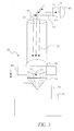
- Fig. 1 is a schematic view of an apparatus for forming the various indicia on a gemstone using near-field optics;
- Figs. 2a, b, and c are schematics illustrating different surfaces on a gemstone, onto which the indicia may be formed using near-field optics;
- Fig. 3 is an enlarged plan view of a gemstone made in accordance with the present invention containing unique micro discrete indicia;
- Fig. 4 is an enlarged partial view of a portion of the gemstone of Fig. 3 illustrating micro discrete indicia;
- Fig. 5 is a schematic view of another embodiment the apparatus for forming the various indicia on a gemstone using near-field optics made in accordance with the present invention;
- Fig. 6 is a schematic view of yet another embodiment the apparatus for forming the various indicia on a gemstone using near-field optics made in accordance with the present invention;
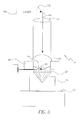
- Fig. 7a is a schematic illustrating a method for locating the indicia on a gemstone described in Fig. 4 made in accordance with the present invention;
- Fig. 7b is an enlarged partial view of a portion of the gemstone of Fig. 7a where the indicia are provided;
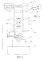
- Fig. 8 is a schematic view of an apparatus used for viewing the micro discrete indicia located on the gemstone described in Fig. 4; and
- Fig. 9 is an enlarged partial view of the image of the micro discrete indicia located on the gemstone displayed by the apparatus described in Fig. 8.
-
- The invention has been described in detail with particular reference to certain preferred embodiments thereof, but it will be understood that variations and modifications can be effected within the spirit and scope of the invention.
- Because of their high value, diamonds and other gemstones are frequently marked for purposes of authentication. Additionally, diamonds and other gemstones are marked for personalization, decorative, or novelty reasons. It is important that such markings do not detract from the appearance of the finished diamond or gemstone. In the authentication of such gemstones, indicia or other markings should not be visible to the purchaser under ordinary use conditions so as to preclude detracting from the finished appearance. For purposes of personalization, novelty, or decoration, such markings should be made with extreme precision, while the desirability for making such markings visible under ordinary use conditions may or may not be a requirement. In either of these situations, the use of near-field optical methods for marking is advantageous since the resolution is higher than conventional means of optical exposure. This enables either a more precise exposure or the production of indicia that are smaller than that produced by conventional means of optical exposure. The invention provides a method and system for marking each gemstone with a unique identification number that is recorded in a data record so it can be used to track the heritage and ownership of the gemstone. The unique identification number can be assigned or registered to an owner, retailer, producer, country of origin, mine, etc.
- The method comprises a system for the creation of unique micro discrete indicia on a gemstone using near-field optics. the gemstone may be a diamond, ruby, sapphire, emerald, opal etc. The micro discrete indicia can be an alphanumeric, a logo, a symbol, a design, etc. The size of each micro discrete indicium is in the range of 2 to 20 microns. The method of identifying the gemstone using the unique micro discrete indicia includes locating and scanning or optically viewing the gemstone and viewing the micro discrete indicia. The obtained micro discrete indicia may be used for a variety of purposes. For example, the identification indicia can be used to identify a particular gemstone on which it is formed. Alternatively, the micro discrete indicia is well suited for authentication of the gemstone. For example, the gemstone is genuine and/or comes from a particular source. Finally, the method may be used for purposes of personalization, ornamentation, decorative, or novelty reasons.
- Referring now to Fig. 1, there is illustrated an
apparatus 10 for forming unique microdiscrete indicia 15 on agemstone 20 such as a diamond.Indicia 15 are created on thegemstone 20 by transmitting light from alight source 45 through amask 25 containing animage 27. Thelight beam 40 from a variety oflaser light sources 45 such as an Excimer, or a frequency doubled Nd:YAG laser passes through themask 27 and is reflected by amirror 50, through alens system 55 and passes through an objective lens 66 of conventional design and impinges onto a solid immersion lens (SIL) 65. Thegemstone 20 resting on astage 70 is placed within a critical distance f. Images formed from such a system will have a lateral spatial resolution that exceeds the classical diffraction limit as is well known to those skilled in the art. Thelight beam 75 passes through anobjective lens 60 of conventional design and impinges onto a solid immersion lens (SIL) 65. TheSIL 65 is positioned within the near-field coupling limit appropriate for the particular lens in use by the use of apositioning device 80. US Patent No. 5,121,256, Corle et al. discloses a method for positioning an SIL using an interferometer constructed between the SIL and the sample. A laser can be used to set up standing waves between the bottom surface of the SIL and the top surface of the sample. In one configuration the laser can be brought into the system through a beam splitter in such a way as to produce plane waves in the region between the bottom of the SIL and the top of the sample. There will be interference between the laser light reflected from the bottom of the SIL and the top of the sample. A path difference of a quarter of a wavelength (λ /4) will cause the interference pattern to change from bright to dark so that controlling the distance between the SIL and the sample to a few nanometers is achieved by sensing the reflected light with a photodiode or the like and using the output as the input to a control system. A number of physical mechanisms play a role in the marking of a diamond or gemstone. Included among these is light-induced ablation of the gemstone material as a result of the rapid deposition of energy from the laser light beam. In some instances a light absorbing material is coated on the diamond or gemstone surface to facilitate direct absorption of the light beam energy. Subsequent conversion of the absorbed energy to heat causes material to be ablated from the near-surface region. Colored gemstones in most instances do not require this surface coating to be applied. It is also possible to alter the color of gemstone materials as a result of the laser light beam affecting the defect concentration in the gemstone or diamond material. It is known to those skilled in the defect physics of such materials that either through direct light absorption into existing defect optical absorption bands or through multi-photon absorption processes, color center can be produced in these materials. The presence of these color centers as a result of the action of the laser light write beam can be determined by a variety of optical methods including absorption or luminescence measurement. Thestage 70 is located on an x, y, z, and translation device 90. Alternatively there are many other known translation devices for positioning thestage 70 in the art such as nano or micro positioning techniques. Theimage 27 used to form the microdiscrete indicia 15 can be an alphanumeric or a symbol such as a logo. If an alphanumeric is used as the micro image, this can also be used as a serial number and/or code for use in further authenticating the gemstone or providing additional information directly from the alphanumeric or be used to look up information from a database. - Referring to Figs. 2a, b, and c, there are illustrated the different surfaces on which the indicia may be formed using near-field optics.
- Referring to Fig. 3, there is illustrated a plan view of the
gemstone 20 containing the microdiscrete indicia 15 shown in an enlarged plan view in Fig 4. Preferably the length "d" of theindicia 15 is no greater than approximately 10 microns and a height "h" is no greater than approximately 2 microns. Theindicia 20 can be of such a size that can be read using near-field optical imaging when placed on the gemstone but not detract from the original appearance as viewed under normal viewing conditions. - Referring now to Fig. 5, there is illustrated another embodiment of the apparatus for forming the various indicia on a gemstone using near-field optics made in accordance with the present invention.
Indicia 15 are created on thegemstone 20 by transmitting light from alaser 100. Thelaser light beam 110 is reflected by amirror 105, through alens system 55 and passes through anobjective lens 60 of conventional design and impinges onto a solid immersion lens (SIL) 65. Thegemstone 20 resting on astage 70 is placed within a critical distance f. TheSIL 65 is positioned within the near-field coupling limit appropriate for the particular lens in use by the use of apositioning device 80. Such a positioning device could be a flying head as is used in hard disk storage devices. Thestage 70 is located on an x, y, z, and translation device 90. Alternately there are many known in the art as nano or micro positioning technologies. Thelaser light beam 110 is used to form theimage 27 of the microdiscrete indicia 15 as shown in Fig. 7. - Referring now to Fig. 6, there is illustrated yet another embodiment of the apparatus for forming the various indicia on a gemstone using near-field optics made in accordance with the present invention.
Indicia 15 are created on thegemstone 20 by transmitting light from alaser 100. Thelaser light beam 110 is reflected by amirror 105, through alens system 55 and passes through a taperedoptical fiber 115. Thegemstone 20 resting on astage 70 is placed within a critical distance f. The taperedoptical fiber 115 is positioned within a critical distance f; images formed from such a system will have a lateral spatial resolution that exceeds the classical diffraction limit as is well known to those skilled in the art. The taperedoptical fiber 115 is positioned within the near-field coupling limit appropriate for the particular tapered optical fiber in use by the use of apositioning device 80. A method for the positioning of such tapered optical fibers includes the measurement of mechanical damping forces as a result of interaction of the fiber tip with the surface of the sample material. This interaction causes a shift of the mechanical resonance frequency for the tip if it is vibrated upon approach towards the surface. As was previously described in Fig. 1, but is done one point at a time. Such a positioning device could be a flying head as is used in hard disk storage devices. Thestage 70 is located on an x, y, z, and translation device 90. Thelaser light beam 110 is used to form theimage 27 of the microdiscrete indicia 15 as shown in Fig. 4. - Referring now to Figs. 7a and 7b, there is illustrated a method for locating the micro
discrete indicia 15 on the surface of thegemstone 20. For each producer of gemstones a unique set of the coordinates (x1, y1) for the location of the microdiscrete indicia 15 can be specified. Using these coordinates the producer's unique microdiscrete indicia 15 can be located from a designatedfeature 128 such as a facet whose location is (x0, y0) or if polar coordinates are used is (r0, 0). In another embodiment the coordinates (x1, y1) or (r1, 1) for the location of the microdiscrete indicia 15 or can be specified on a document of authenticity (not shown), which can accompany eachgemstone 20. The location (x1; y1) or (r1, 1) of theindicia 15 can be given from the designatedfeature 128 such as a facet whose location is (x0, y0) or if polar coordinates are used is (r0, 0). In yet another embodiment of the present invention, theindicia 15 can be located by repeatedly forming theindicia 15 using the near-field apparatus 10 creating a set ofindicia 125. The set ofindicia 125 forms a mark having a length "1" and height "s", which is visible through a normal optical microscope (not shown) and can be located using the normal optical microscope. The length "1" and height "s" can be of a range of between .02 millimeters to .1 millimeter depending on the magnification of the viewing microscope or viewing eye loop used. After the set ofindicia 125 has been located, the near-field optical apparatus 200 (described in Fig. 8) is used to read the individual microdiscrete indicia 15, which by itself is not readable unless view through the near-field apparatus 200. - Once it has been determined that
indicia 15 is present, referring now to Fig. 8, there is illustrated theapparatus 200 for locating and viewing theindicia 15 formed on thegemstone 20. Theindicia 15 on thegemstone 20 can be viewed using magnifyingimaging device 200 or used to capture an image of theindicia 15. Alight beam 202 from alight source 204 reflects from abeam splitter 206 and passes through anobjective lens 208 of conventional design and impinges onto a solid immersion lens (SIL) 210. Thegemstone 20 resting on astage 212 is placed within a critical distance f. TheSIL 210 is positioned within the near-field coupling limit appropriate for the particular lens in use by the use of apositioning device 220. Such a positioning device could be a flying head as is used in hard disk storage devices. Thelight beam 202 is reflected from thegemstone 20, passes through theSIL 210, theobjective lens 208, and thebeam splitter 206, imaging theindicia 15 onto asensor 226 by alens system 224. Thestage 212 is located on an x, y, z, and translation device 228. The x, y, z, and translation device 228 is and connected to thescanner 224 by a logic, control andmemory unit 230. Referring now to Fig. 9, an enlarged partial view of theimage 232 of theindicia 15 captured by thedevice 200 is shown. Using theimaging device 200, the image of theindicia 15 on thegemstone 20 is displayed for viewing for authentication and identification purposes. The size of theindicia 15 is such that theindicia 15 can appear on one or more surfaces of thegemstone 20 as shown in Figs. 2a, b, and c. Theindicia 15 formed on thegemstone 20 are of a size such that they are not visually discernable on thegemstone 20 with the unaided eye under normal viewing conditions or detract from the overall original appearance of thegemstone 20. As previously discussed, the size is preferably no greater than about 20 microns, and is generally in the range of about 2 to 20 microns. In situations where the micro discrete indicia is used for the purpose of personalization, ornamentation, decorative, or novelty the size of the micro discrete indicia may be made as large as deemed appropriate. The size of the micro discrete indicia for personalization or ornamentation may be but is not limited to a size range of 0.1 millimeters or larger. The size can be such that it can be viewed by the user with an unaided eye or with the use of a low power loop. - The method comprises creation of the unique micro
discrete indicia 15 using theapparatus 10 as described in Fig. 1. The uniquediscrete indicia 15 represents a unique identification number assigned or registered to an individual or business which directly links the individual or business such as a retailer, producer, country of origin, or mine to thegemstone 20. The uniquediscrete indicia 15 are formed on thegemstone 20 using near-field optics. The unique identification number is then stored in a table as shown in Table 1 on a database and linked with information such as carat, clarity, cut, color etc describing the gemstone, the information describing the owner, retailer, producer, country of origin, and/or mine along with the exact location on thegemstone 20 of the microdiscrete indicia 15. The location of the micro discrete indicia can be the given for a specific gemstone cut such as a marquis, baguette, solitaire, etc. The location of the micro discrete indicia can be also be designated by the owner, retailer, producer, country of origin, and/or mine as described in Figs. 7a and 7b. To determine the authenticity of thegemstone 20 the unique identification number is obtained by scanning the uniquediscrete indicia 15 on thegemstone 20 using the near-fieldoptical imaging apparatus 200 as described in Figs. 8 and 9. The unique identification number is looked up on the table located in the database and the associated information is retrieved. The owner, insurance company, retailer, law enforcement, producer, gem cutters and or mine can use the unique identification number and the database to identify a particular gemstone as to where the gemstone was mined, cut, who produced the gemstone, who sold the gemstone and who bought or owns the gemstone and to insure the gemstone is authentic. As can be seen from the foregoing the providing of micro discrete indicia on gemstones made in accordance with the present invention provides a method for allowing independent verification of the authenticity and/or the source of a gemstone directly from the gemstone, and also provides a mechanism for personalization, novelty, or decoration of such products.ID Number Type of Gemstone Country of Origin Producer Cuter Retailer Owner Description Mine A12345678 Diamond Botswana DeBeers Diamond Patton's Fine Jewelry John Spoonhower Carat = 2 Debswana Factory 12 First Street 34 Park Avenue Cut = Baguene Mining Company Amsterdam Webster, NY 14580 Rochester, NY Color = E Clarity = VVS 8959R3652 Emerald Columbia Gem Labs Gem Labs Patton's Fine Jewelry Juliana McClain Carat =1.07 Coscuez Mines 12 First St. 8 Central Park W. 7.0x5.0mm Emerald Cut Webster, NY 14580 New York. NY Strong Strongly Bluish Green Slightly Included
Claims (10)
- A method for providing micro-discrete indicia on a gemstone, comprising the steps of:providing a gemstone;selecting an area on said gemstone for placement of a micro-discrete indicia; andforming said micro-discrete indicia on said gemstone using near-field optics.
- A method for reading a micro-discrete indicia on a gemstone, comprising the steps of:locating said micro-discrete indicia on said gemstone; andreading said micro-discrete indicia using near-field optics.
- A gemstone having a micro-discrete indicia formed thereon wherein said micro-discrete indicia image was formed using near-field optics.
- A method according to claim 2 wherein said micro-discrete indicia is located initially located using an eye-loop and/or a microscope.
- A method according to claim 2 wherein said micro-discrete indicia is located by using predetermined coordinates associated with the characteristics of said gemstone.
- A method according to claim 2 where a document is provided that designates the appropriate coordinates of the micro-discrete indicia of said gemstone.
- A invention according to claim 1, 2 or 3 wherein said micro-discrete indicia has a size no greater than about 20 microns.
- A invention according to claim 1, 2 or 3 wherein said micro-discrete indicia comprises a logo.
- A invention according to claim 1, 2 or 3 wherein in micro-discrete indicia is associated with a particular retail establishment that sold said gemstone.
- A invention according to claim 1, 2 or 3 wherein in micro-discrete indicia is associated with a particular producer, country of origin, mine of said gemstone.
Applications Claiming Priority (2)
| Application Number | Priority Date | Filing Date | Title |
|---|---|---|---|
| US27016 | 2001-12-21 | ||
| US10/027,016 US6624385B2 (en) | 2001-12-21 | 2001-12-21 | Method for marking gemstones with a unique micro discrete indicia |
Publications (1)
| Publication Number | Publication Date |
|---|---|
| EP1321305A2 true EP1321305A2 (en) | 2003-06-25 |
Family
ID=21835168
Family Applications (1)
| Application Number | Title | Priority Date | Filing Date |
|---|---|---|---|
| EP02080196A Withdrawn EP1321305A2 (en) | 2001-12-21 | 2002-12-09 | Method for making gemstones with a unique micro discrete indicia |
Country Status (2)
| Country | Link |
|---|---|
| US (3) | US6624385B2 (en) |
| EP (1) | EP1321305A2 (en) |
Cited By (9)
| Publication number | Priority date | Publication date | Assignee | Title |
|---|---|---|---|---|
| WO2007020493A1 (en) * | 2005-08-19 | 2007-02-22 | L'universite De Geneve | Method, arrangement and sign for authenticating an object |
| WO2006130887A3 (en) * | 2005-06-09 | 2008-07-10 | Swarovski & Co | Marked member made of transparent material, and production method |
| RU2421816C2 (en) * | 2008-12-11 | 2011-06-20 | Смирнов Владимир Алексеевич | Device with identification numerical number |
| AT511056B1 (en) * | 2011-03-07 | 2012-09-15 | Swarovski D Kg | LASER MARKED SUBJECT |
| US20240104326A1 (en) * | 2022-12-15 | 2024-03-28 | EllansaLabs Inc. | Systems for authentication and related devices and methods |
| WO2024129847A1 (en) * | 2022-12-15 | 2024-06-20 | EllansaLabs Inc. | System and method authenticating an integrated circuit using a diamond-based read-only memory |
| US12160533B2 (en) | 2022-04-20 | 2024-12-03 | EllansaLabs Inc. | System and method for etching internal surfaces of transparent gemstones with information pertaining to a blockchain |
| US12213295B2 (en) | 2023-03-15 | 2025-01-28 | EllansaLabs Inc. | Diamond-based electromagnetic interference shield |
| US12368585B2 (en) | 2022-04-20 | 2025-07-22 | EllansaLabs Inc. | System and method for internal etching of transparent materials with information pertaining to a blockchain |
Families Citing this family (23)
| Publication number | Priority date | Publication date | Assignee | Title |
|---|---|---|---|---|
| US5932119A (en) * | 1996-01-05 | 1999-08-03 | Lazare Kaplan International, Inc. | Laser marking system |
| US6624385B2 (en) * | 2001-12-21 | 2003-09-23 | Eastman Kodak Company | Method for marking gemstones with a unique micro discrete indicia |
| US7994450B2 (en) * | 2002-01-07 | 2011-08-09 | International Business Machines Corporation | Debris minimization and improved spatial resolution in pulsed laser ablation of materials |
| US20030120613A1 (en) * | 2003-01-28 | 2003-06-26 | Jayant Neogi | Customizing objects and materials with digital identifiers |
| US20050193766A1 (en) * | 2004-03-03 | 2005-09-08 | Pasmanik Guerman A. | System and method for viewing micro-markings on jewelry and other objects |
| US20050274144A1 (en) * | 2004-06-09 | 2005-12-15 | Goughnour Roy R | Multiplet jewelry product and method of manufacture |
| US20060066877A1 (en) * | 2004-09-30 | 2006-03-30 | Daniel Benzano | Capture and display of image of three-dimensional object |
| US20060144821A1 (en) * | 2005-01-04 | 2006-07-06 | Academia Sinica | Method for engraving irreproducible pattern on the surface of a diamond |
| US7284396B2 (en) * | 2005-03-01 | 2007-10-23 | International Gemstone Registry Inc. | Method and system for laser marking in the volume of gemstones such as diamonds |
| US20070005486A1 (en) * | 2005-06-30 | 2007-01-04 | Collectors Universe, Inc. | Process for verifying, labeling and rating diamonds and other gemstones from mine to market |
| US20070118409A1 (en) * | 2005-11-22 | 2007-05-24 | Artinger Charles K | Methods and system for processing insurance claims for damaged gemstones |
| US20070209390A1 (en) * | 2006-03-06 | 2007-09-13 | Jack Malinowski | Multiplet gemstones with directly printed embedded translucent images |
| US20090269702A1 (en) * | 2008-04-29 | 2009-10-29 | Direct Shopping Network, Llc | Method for introducing inclusion image into gemstone |
| US20120098971A1 (en) * | 2010-10-22 | 2012-04-26 | Flir Systems, Inc. | Infrared binocular system with dual diopter adjustment |
| SG10201506282WA (en) | 2015-08-12 | 2017-03-30 | Jubilee Diamond Instr S Pte Ltd | Diamond Identification Apparatus |
| US9888742B2 (en) | 2015-09-11 | 2018-02-13 | Nike, Inc. | Article of footwear with knitted component having plurality of graduated projections |
| WO2017208053A1 (en) | 2016-06-01 | 2017-12-07 | Jubilee Diamond Instrument (S) Pte.Ltd. | Precious stone testing device |
| WO2018213294A1 (en) * | 2017-05-15 | 2018-11-22 | The Trustees Of The University Of Pennsylvania | Systems and methods for laser cleaving diamonds |
| US10989667B2 (en) | 2017-06-01 | 2021-04-27 | Jubilee Diamond Instrument (S) Pte. Ltd. | UV reflection tester |
| GB2584876A (en) | 2019-06-19 | 2020-12-23 | Jubilee Diamond Instr S Pte Ltd | Gemstone testing apparatus |
| RU2751986C1 (en) * | 2020-04-17 | 2021-07-21 | Общество с ограниченной ответственностью «Микролазер» (ООО «Микролазер») | Space code for recording information inside a transparent object with the ability to read from any direction |
| JP2022164940A (en) * | 2021-04-18 | 2022-10-28 | 株式会社シンテック | Engraved diamond crystal and method for manufacturing the same |
| KR20240118023A (en) * | 2023-01-26 | 2024-08-02 | 프랑크 치머 홀딩 아게 | Method and system for determining authenticity of a manufactured diamond |
Family Cites Families (23)
| Publication number | Priority date | Publication date | Assignee | Title |
|---|---|---|---|---|
| US4200506A (en) * | 1977-11-08 | 1980-04-29 | Dreschhoff Gisela A M | Process for providing identification markings for gemstones |
| US4392476A (en) * | 1980-12-23 | 1983-07-12 | Lazare Kaplan & Sons, Inc. | Method and apparatus for placing identifying indicia on the surface of precious stones including diamonds |
| US4467172A (en) * | 1983-01-03 | 1984-08-21 | Jerry Ehrenwald | Method and apparatus for laser engraving diamonds with permanent identification markings |
| US4809417A (en) * | 1986-01-31 | 1989-03-07 | George Normann & Associates | Method of making a multiplet jewelry product with internally embedded visual indicia |
| US4847183A (en) * | 1987-09-09 | 1989-07-11 | Hewlett-Packard Company | High contrast optical marking method for polished surfaces |
| US5149938A (en) | 1990-10-11 | 1992-09-22 | Harry Winston, S.A. | Methods for producing indicia on diamonds |
| US5410125A (en) | 1990-10-11 | 1995-04-25 | Harry Winston, S.A. | Methods for producing indicia on diamonds |
| US5272330A (en) | 1990-11-19 | 1993-12-21 | At&T Bell Laboratories | Near field scanning optical microscope having a tapered waveguide |
| US5121256A (en) | 1991-03-14 | 1992-06-09 | The Board Of Trustees Of The Leland Stanford Junior University | Lithography system employing a solid immersion lens |
| US5393976A (en) * | 1992-11-26 | 1995-02-28 | Kabushiki Kaisha Topcon | Apparatus for displaying a sample image |
| DE4243489A1 (en) * | 1992-12-22 | 1994-06-23 | Zeiss Carl Fa | Process for lighting with a focused electron beam and associated electron-optical lighting system |
| JPH07108007A (en) * | 1993-10-13 | 1995-04-25 | Daiwa Kako Kk | Ornament |
| US5721687A (en) * | 1995-02-01 | 1998-02-24 | The Regents Of The University Of California Office Of Technology Transfer | Ultrahigh vacuum focused ion beam micromill and articles therefrom |
| US5760367A (en) * | 1995-05-16 | 1998-06-02 | Engraving Technologies, Inc. | Apparatus and method of engraving indicia on gemstones, and gemstones, produced thereby |
| US5753887A (en) | 1995-05-16 | 1998-05-19 | Engraving Technologies, Inc. | Apparatus for laser engraving indicia on gemstones |
| GB9514558D0 (en) | 1995-07-17 | 1995-09-13 | Gersan Ets | Marking diamond |
| US5932119A (en) | 1996-01-05 | 1999-08-03 | Lazare Kaplan International, Inc. | Laser marking system |
| US6230071B1 (en) * | 1996-05-24 | 2001-05-08 | The Regents Of The University Of California | Depth enhancement of ion sensitized data |
| US5773116A (en) * | 1996-08-01 | 1998-06-30 | The Regents Of The University Of California, Ofc. Of Technology Transfer | Focused ion beam micromilling and articles therefrom |
| IL124592A (en) * | 1997-05-23 | 2002-07-25 | Gersan Ets | Method of marking a gemstone or diamond |
| GB2325439A (en) * | 1997-05-23 | 1998-11-25 | Gersan Ets | Marking diamond gemstone by plasma or ion beam etching through a laser ablated resist |
| US6710943B2 (en) * | 2001-05-18 | 2004-03-23 | David Alan Weir | Viewer for laser-inscribed diamonds |
| US6624385B2 (en) * | 2001-12-21 | 2003-09-23 | Eastman Kodak Company | Method for marking gemstones with a unique micro discrete indicia |
-
2001
- 2001-12-21 US US10/027,016 patent/US6624385B2/en not_active Expired - Fee Related
-
2002
- 2002-12-09 EP EP02080196A patent/EP1321305A2/en not_active Withdrawn
-
2003
- 2003-06-26 US US10/607,184 patent/US20040008888A1/en not_active Abandoned
- 2003-06-26 US US10/607,185 patent/US20040000575A1/en not_active Abandoned
Cited By (12)
| Publication number | Priority date | Publication date | Assignee | Title |
|---|---|---|---|---|
| WO2006130887A3 (en) * | 2005-06-09 | 2008-07-10 | Swarovski & Co | Marked member made of transparent material, and production method |
| WO2007020493A1 (en) * | 2005-08-19 | 2007-02-22 | L'universite De Geneve | Method, arrangement and sign for authenticating an object |
| RU2421816C2 (en) * | 2008-12-11 | 2011-06-20 | Смирнов Владимир Алексеевич | Device with identification numerical number |
| AT511056B1 (en) * | 2011-03-07 | 2012-09-15 | Swarovski D Kg | LASER MARKED SUBJECT |
| AT511056A4 (en) * | 2011-03-07 | 2012-09-15 | Swarovski D Kg | LASER MARKED SUBJECT |
| US10365499B2 (en) | 2011-03-07 | 2019-07-30 | D. Swarovski Kg | Laser-marked article with moire pattern |
| US12160533B2 (en) | 2022-04-20 | 2024-12-03 | EllansaLabs Inc. | System and method for etching internal surfaces of transparent gemstones with information pertaining to a blockchain |
| US12368585B2 (en) | 2022-04-20 | 2025-07-22 | EllansaLabs Inc. | System and method for internal etching of transparent materials with information pertaining to a blockchain |
| US20240104326A1 (en) * | 2022-12-15 | 2024-03-28 | EllansaLabs Inc. | Systems for authentication and related devices and methods |
| WO2024129847A1 (en) * | 2022-12-15 | 2024-06-20 | EllansaLabs Inc. | System and method authenticating an integrated circuit using a diamond-based read-only memory |
| WO2024129840A1 (en) * | 2022-12-15 | 2024-06-20 | EllansaLabs Inc. | Systems for authentication and related devices and methods |
| US12213295B2 (en) | 2023-03-15 | 2025-01-28 | EllansaLabs Inc. | Diamond-based electromagnetic interference shield |
Also Published As
| Publication number | Publication date |
|---|---|
| US6624385B2 (en) | 2003-09-23 |
| US20040008888A1 (en) | 2004-01-15 |
| US20040000575A1 (en) | 2004-01-01 |
| US20030121897A1 (en) | 2003-07-03 |
Similar Documents
| Publication | Publication Date | Title |
|---|---|---|
| US6624385B2 (en) | Method for marking gemstones with a unique micro discrete indicia | |
| JP4885151B2 (en) | Method and system for laser marking in the volume of gemstones such as diamond | |
| US8893973B2 (en) | Coded articles and systems and methods of identification of the same | |
| JP3238875B2 (en) | Apparatus and method for micro-engraving by laser energy | |
| JP2587762B2 (en) | How to seal a diamond | |
| AU2017321840B2 (en) | Information display medium and manufacturing method relating thereto | |
| US8319145B2 (en) | System and method for gemstone micro-inscription | |
| CN112771595B (en) | Light-transmitting mark for precious stone mark | |
| TWI744841B (en) | Method for creation and detection of optically permeable image inside a diamond and detection systems (options) | |
| RU2750068C1 (en) | Method for information recording inside diamond crystal | |
| JP5269603B2 (en) | Engraved gem viewer | |
| ATE545518T1 (en) | DATA CARRIER WITH MARKINGS INSCRIBED BY LASER BEAM AND METHOD FOR PRODUCING IT | |
| US20050274144A1 (en) | Multiplet jewelry product and method of manufacture | |
| EP0833755B1 (en) | Monitoring of covert marks | |
| US20250289258A1 (en) | Method for forming micro-pattern on surface of product, and product having micro-pattern formed thereon by applying method | |
| RU2357870C1 (en) | Method and system for laser marking precious stones, such as diamonds | |
| EP2394816B1 (en) | Procedure for marking, encryption, labelling and optical coding | |
| BE877326A (en) | METHOD AND DEVICE FOR MARKING GEMSTONES | |
| US20030081300A1 (en) | Digital analog recording using near field optical imaging | |
| JP2005270993A (en) | Material surface processing method by pulse laser, surface processing data processing method, replica plate manufacturing method, information carrier and identification information | |
| EP1202776A1 (en) | Method apparatus and article of manufacture for a branding diamond branding with a focused ion beam | |
| RU2857753C2 (en) | Object verification system and methods of using same | |
| CN114258341A (en) | Method of marking solid material, mark formed by the method and solid material marked according to the method | |
| Meinertz et al. | Precision marking of glass with excimer lasers: Laser‐generated microstructures and material modifications serve as colored marks | |
| JP4143769B2 (en) | Gradation laser marking method |
Legal Events
| Date | Code | Title | Description |
|---|---|---|---|
| PUAI | Public reference made under article 153(3) epc to a published international application that has entered the european phase |
Free format text: ORIGINAL CODE: 0009012 |
|
| AK | Designated contracting states |
Designated state(s): AT BE BG CH CY CZ DE DK EE ES FI FR GB GR IE IT LI LU MC NL PT SE SI SK TR |
|
| AX | Request for extension of the european patent |
Extension state: AL LT LV MK RO |
|
| STAA | Information on the status of an ep patent application or granted ep patent |
Free format text: STATUS: THE APPLICATION IS DEEMED TO BE WITHDRAWN |
|
| 18D | Application deemed to be withdrawn |
Effective date: 20050702 |