EP1321248A1 - Authoring system and authoring method, and storage medium - Google Patents
Authoring system and authoring method, and storage medium Download PDFInfo
- Publication number
- EP1321248A1 EP1321248A1 EP01970302A EP01970302A EP1321248A1 EP 1321248 A1 EP1321248 A1 EP 1321248A1 EP 01970302 A EP01970302 A EP 01970302A EP 01970302 A EP01970302 A EP 01970302A EP 1321248 A1 EP1321248 A1 EP 1321248A1
- Authority
- EP
- European Patent Office
- Prior art keywords
- data
- action
- editing
- sound
- chronological
- Prior art date
- Legal status (The legal status is an assumption and is not a legal conclusion. Google has not performed a legal analysis and makes no representation as to the accuracy of the status listed.)
- Withdrawn
Links
Images








Classifications
-
- G—PHYSICS
- G05—CONTROLLING; REGULATING
- G05B—CONTROL OR REGULATING SYSTEMS IN GENERAL; FUNCTIONAL ELEMENTS OF SUCH SYSTEMS; MONITORING OR TESTING ARRANGEMENTS FOR SUCH SYSTEMS OR ELEMENTS
- G05B19/00—Program-control systems
- G05B19/02—Program-control systems electric
- G05B19/04—Program control other than numerical control, i.e. in sequence controllers or logic controllers
- G05B19/05—Programmable logic controllers, e.g. simulating logic interconnections of signals according to ladder diagrams or function charts
-
- B—PERFORMING OPERATIONS; TRANSPORTING
- B25—HAND TOOLS; PORTABLE POWER-DRIVEN TOOLS; MANIPULATORS
- B25J—MANIPULATORS; CHAMBERS PROVIDED WITH MANIPULATION DEVICES
- B25J9/00—Program-controlled manipulators
- B25J9/16—Program controls
- B25J9/1656—Program controls characterised by programming, planning systems for manipulators
- B25J9/1671—Program controls characterised by programming, planning systems for manipulators characterised by simulation, either to verify existing program or to create and verify new program, CAD/CAM oriented, graphic oriented programming systems
-
- G—PHYSICS
- G05—CONTROLLING; REGULATING
- G05B—CONTROL OR REGULATING SYSTEMS IN GENERAL; FUNCTIONAL ELEMENTS OF SUCH SYSTEMS; MONITORING OR TESTING ARRANGEMENTS FOR SUCH SYSTEMS OR ELEMENTS
- G05B19/00—Program-control systems
- G05B19/02—Program-control systems electric
- G05B19/04—Program control other than numerical control, i.e. in sequence controllers or logic controllers
- G05B19/042—Program control other than numerical control, i.e. in sequence controllers or logic controllers using digital processors
- G05B19/0426—Programming the control sequence
-
- G—PHYSICS
- G05—CONTROLLING; REGULATING
- G05B—CONTROL OR REGULATING SYSTEMS IN GENERAL; FUNCTIONAL ELEMENTS OF SUCH SYSTEMS; MONITORING OR TESTING ARRANGEMENTS FOR SUCH SYSTEMS OR ELEMENTS
- G05B2219/00—Program-control systems
- G05B2219/20—Pc systems
- G05B2219/23—Pc programming
- G05B2219/23267—Program derived from sequence time diagram and stored in table
-
- G—PHYSICS
- G05—CONTROLLING; REGULATING
- G05B—CONTROL OR REGULATING SYSTEMS IN GENERAL; FUNCTIONAL ELEMENTS OF SUCH SYSTEMS; MONITORING OR TESTING ARRANGEMENTS FOR SUCH SYSTEMS OR ELEMENTS
- G05B2219/00—Program-control systems
- G05B2219/20—Pc systems
- G05B2219/26—Pc applications
- G05B2219/2666—Toy
Definitions
- This invention relates to an authoring system and an authoring method for supporting creation and editing of data in accordance with a preset scenario and, more particularly, to an authoring system and an authoring method for supporting creation and editing of a sequence of commands/data stating a preset operating pattern of a robot.
- an authoring system and an authoring method for supporting creation and editing of an operating pattern using a set of components prescribing the operating states of a robot and to an authoring system and an authoring method for arraying the respective components on a computer display for supporting creation and editing of the operating pattern.
- robot A mechanical apparatus for performing movements simulating the movement of the human being, using electrical or magnetic operation, is termed a "robot".
- the etymology of the term robot is said to be "ROBOTA" (slave machine) of the Slavic language.
- ROBOTA slave machine
- the robots started to be used widely in this country towards the end of the sixtieth. Most of the robots used were industrial robots, such as manipulators or transporting robots, aimed at automation or unmanned operations in plants.
- legged mobile robots including pet type robots, simulating the bodily mechanism or movements of animals, such as quadruples, e.g., dogs or cats, or so-called humanoid robots, simulating the bodily mechanism or movements of animals erected and walking on feet, such as human being, are progressing, and expectations are made of practical utilization of these types of robots.
- the legged mobile robots while being unstable and difficult to control as to their orientation or walking, as compared to crawler or tire type robots, are superior in their performance in climbing up and down a ladder or a staircase, in riding over obstacles or walking or in running flexibly on a leveled or non-leveled terrain.
- the standstill type robots installed and used at a fixed place, such as armed robots, are in operation only in a stationary or local working space, such as for assembling or sorting of component parts.
- the mobile robots are not limited as to working space and are movable on a preset or undefined path in an unrestricted fashion to perform operations to take the place of human operators or to offer variegated services to take the place of the human being, dogs or other living organisms.
- One of the usages of the legged mobile robot is substitution of a variety of operations dangerous or difficult to perform in industrial or productive activities. Examples of these usages include substitution of a variety of operations dangerous or difficult to perform, such as maintenance operations in nuclear power plants, thermal power plants or petrochemical plants, transporting or assembling operations in manufacturing plants, cleaning in high-rise buildings or rescuing e.g., on the site of conflagrations.
- Another usage of the legged mobile robot is life-related usage, such as co-living with or rendering entertainment for the human being, rather than acting as the operational support described above.
- This sort of robot emulates a rich feeling expression exploiting the four limbs or an operation mechanism of the legged walking animal of high intellect, such as human being or dog (pet).
- this sort of the robot is requested not only to execute the pre-set operating pattern measly faithfully, but also to realize vivid expressions dynamically responding to the language or behavior of a counterpart operator, such as 'praising', 'scolding' or 'patting'.
- an intellectual robot owns a behavioral or learning model, emanating from movements, and determines its movements as it varies the model based on the input information from outside, such as speech, image or tactile feeling, to realize autonomous thinking or operation control.
- the feeling or the autonomous behavior of the robot itself can be represented by providing the robot with the feeling or instinct model.
- the legged mobile robot owns a high information processing capability, such that the robot itself may be thought of as a sort of a computing system. Consequently, the sequence of the highly advanced sophisticated operations, constructed by the operating pattern, realized on the robot, or by the combination of plural basic operating patterns, may be constructed by an operation similar to that performed in the computer programming.
- An authoring system is such a system supporting the creation and editing of an action of a multi-joint structure comprised of a combination of a plurality of chronological data, including a user inputting unit for inputting commands or data from a user, a user presenting unit for presenting an editing area in which chronological data making up the action are arrayed chronologically along the time axis, and a chronological data editing unit provided for each chronological data making up the action.
- the chronological data editing unit creates or edits relevant chronological data based on a user input through the user presenting unit.
- the 'system' herein means a logical assembly of plural devices or functional modules realizing specified functions, without regard to whether or not the individual devices or functional modules are enclosed in one casing.
- the multi-joint structure is a legged robots having two legs, four legs and so forth and which are constructed from plural joint actuators.
- the multi-joint structure may be other types of multi-joint robots, or a character for producing an animation, based on joint movements, as a result of computer graphics.
- the chronological data making up the action may be motion data stating the chronological movements of respective joints of the multi-joint structure.
- the motion data may prescribe chronological movements of respective joints of the multi-joint structure and, by arraying two or more keyframes, each representing the multi-joint structure striking a preset pose on the time axis, may smoothly join the respective keyframes.
- Another chronological data making up the action is sound data output as sound in timed relation to reproduction of the action.
- the sound data may be stated in the MIDI (Musical Instrumental Digital Interface) form or WAVE form.
- indicator display data stating the turning on/off of display indicators displayed in timed relation to action reproduction.
- the indicator display data may be stated in the MIDI (Musical Instrumental Digital Interface) form.
- the editing area presented by the user presenting unit may be comprised of chronological-data-based chronological data display channels. These data extend along the horizontally arrayed time axis, with the display channels being arrayed in the vertical direction.
- the chronological data making up an action of the mobile robot may be displayed as they are arrayed along the time axis on the time table of the two-dimensional time line style. Consequently, the creation and editing may be prosecuted as synchronization between the respective chronological data is visually checked so that a working environment efficient and intuitively comprehensible may be provided for action editing.
- the editing area presented by the user presenting unit may include one or more time display lines extending in the vertical direction for specifying the relevant time as prescribed by the time ruler.
- the state of progress between the respective time indicating lines or the state of synchronization between the respective chronological data channels may be visually checked with the time indicating lines as a reference.
- the editing area presented by the user presenting unit may include a vertically extending current time display line for indicating the current time on the time axis prescribed by the time ruler.
- the current time display line may be configured for being shifted on the time ruler to a position corresponding to user actuation.
- the editing area presented by the user presenting unit may include a display window for previewing movements of the multi-joint structure at the current time.
- the editing area presented by the user presenting unit may include a keyframe channel for indicating the respective keyframes or thumbnails thereof along the time axis as prescribed by the time ruler.
- the time changes of the keyframe may be accommodated so as to follow up with keyframe or thumbnail dragging.
- a pose editing picture for editing a relevant pose may be started responsive to the operation of selection by the user of the keyframe or thumbnail within the keyframe channel.
- the editing area presented by the user presenting unit may also include a motion channel for editing and displaying the contents of a motion along the time axis prescribed by the time ruler.
- This motion channel is constructed by arraying respective timing charts, representing the chronological movements of respective joints of the multi-joint structure in the vertical direction. It is also possible to accommodate changes in the joint movements at a relevant time point so as to follow up with dragging on the timing chart in the motion channel.
- the editing area presented by the user presenting unit may also be provided with a sound channel for indicating the contents of the sound along the time axis as prescribed by the time ruler, or with a display indicator channel for displaying the contents of the indicator display data along the time axis prescribed by the time ruler.
- the user presenting unit may also be provided with a sound editing area for displaying and editing the sound contents along the time axis prescribed by the time ruler.
- the sound editing area may include a score channel constituted by a basic grid along the time axis direction and by a piano keyboard.
- a score is formed by the sound duration as the reference of the time axis and the pitch of the piano keys.
- the sound may be edited by arraying the color corresponding to sound notes in a cell corresponding to the desired time point and the sound scale.
- the velocity channel may also be demonstrated for representing the intensity of each sound along the time axis.
- the user presenting unit may further include an indicator editing area for displaying and editing the contents of indicator data along the time axis prescribed by the time ruler.
- the indicator editing area includes a score channel constituted by a list of sites of arraying of display indicators and by the basic grid along the time axis direction.
- a score may be edited from one site list to another by indicating the turned-on state of the indicator in each site on the time axis on a score channel.
- the user presenting unit may further display a preview window for visually checking an action of the multi-joint structure generated based on each chronological data as edited by the chronological data editing unit.
- the preview window may include a 3D view area for three-dimensional display of movements of the multi-joint structure generated based on motion data.
- the preview window may include a display indicator operation preview area for displaying the operation of the indicators corresponding to the indicator display data in synchronism with the preview of other chronological data.
- the user presenting unit may further display a pose window for editing the pose of the multi-joint structure by the GUI operation.
- the pose window may include an entity specifying area for displayingthe multi-joint structure in a developed plan view for accepting user selection of editable sites.
- the authoring pose window may include a list specifying area for displaying a list of editable sites of the multi-joint structure and setting values thereof.
- the pose window may also include a setting value area for displaying a list of the names of setting sites, setting values, settable maximum values and settable minimum values of editable sites of the multi-joint structure.
- the pose window may also include a 3D display area for 3D displaying a full image of the multi-joint structure generated by 3D graphics and for accepting user selection on the 3D display.
- the authoring system may also include data inputting means for inputting chronological data making up an action of the multi-joint structure from outside.
- the pose window may also display the pose generated based on data input from the data inputting means.
- the user presenting unit may further display a motion preview window arraying one or more key frames making up the motion or thumbnails thereof in accordance with the chronological sequence used in motion reproduction.
- An authoring method is such a method for supporting the creation and editing of an action of a multi-joint structure comprised of a combination of a plurality of chronological data, and includes a user presenting step of presenting an editing area in which the chronological data making up the action are arrayed chronologically along the time axis and a chronological data editing step for creating or editing relevant chronological data based on a user input through the editing area, provided for each chronological data making up the action, via the user presenting step.
- One of the chronological data making up the action is motion data stating the chronological movements of respective joints of the multi-joint structure.
- This motion data may prescribe chronological movements of respective joints of the multi-joint structure.
- the motion data smoothly joins two or more keyframes by arraying these keyframes each representing the multi-joint structure striking a preset pose on the time axis.
- chronological data making up the action is sound data output as sound in timed relation to reproduction of the action.
- the sound data maybe stated in the MIDI (Musical Instrumental Digital Interface) form or WAVE form.
- display indicator display data stating the turning on/off of display indicators, with the display data being displayed in timed relation to reproduction of the action.
- the indicator display data may be stated in the MIDI (Musical Instrumental Digital Interface) form.
- the editing area presented in the user presenting step may be comprised of chronological-data-based chronological data display channels, with the data extending along the horizontally arrayed time axis, the channels being arrayed in the vertical direction.
- the chronological data forming the action of the mobile robot such as motion data, sound data or LED operating data
- the chronological data forming the action of the mobile robot may be arrayed and displayed along the time axis on the timetable of the two-dimensional time line style to render it possible to visually check the synchronization between respective chronological data in prosecuting the creation or editing.
- the editing area presented in the user presenting step may include a time ruler comprised of graduations used to display the time axis in real-time. In such case, it is possible to readily visually recognize the synchronization between the respective chronological data channels and the time axis.
- the editing area presented by the user presenting step may include one or more time display lines extending in the vertical direction for indicating the relevant time prescribed by a time ruler.
- the state of progress between the respective time indicating lines or the state of synchronization between the respective chronological data channels may be visually checked with the time indicating lines as a reference.
- the user presenting step may present an editing area having a vertically extending current time display line for indicating the current time on the time axis prescribed by the time ruler. There may further be included a further step of shifting the current time display line on the time ruler to a position corresponding to user actuation.
- the user presenting step may further present an editing area having a keyframe channel for demonstrating each keyframe or its thumbnail in accordance with the time axis prescribed by the time ruler.
- there may further be provided a step of changing the keyframe time so as to follow up with dragging of the keyframe or its thumbnail in the keyframe channel.
- There may also be provided a step of starting a pose editing picture for editing the relevant pose responsive to the user's operation for selecting the keyframe or its thumbnail in the keyframe channel.
- the user presenting step may also present an editing area provided with a motion channel for editing and displaying the motion contents along the time axis prescribed by the time ruler.
- the respective timing charts representing the chronological movements of the respective joints of the multi-joint structure may be arrayed vertically to represent the motion channel.
- There may further be provided a step of changing the joint movements at the relevant time points such as to follow up with dragging on the timing charts in the motion channel.
- the user presenting step there may be presented an editing area having a sound channel for demonstrating the sound contents along the time axis prescribed by the time ruler.
- the user presenting step may present an editing area having a display indicator channel for displaying the contents of the indicator display data along the time axis prescribed by the time ruler.
- the authoring method may further include a step of displayingthe sound editing area for displaying and editing the sound contents along the time axis prescribed by the time ruler.
- the sound editing area may include a score channel constituted by a basic grid along the time axis direction and a piano keyboard. In such case, a score is formed by the sound duration as the reference of the time axis and by the pitch of the piano keys. On the score channel, the sound may be edited by arraying the color corresponding to sound notes in a cell corresponding to the desired time point and the sound scale on the score channel.
- the sound editing area may also include a velocity channel for representing the intensity of each sound along the time axis.
- the authoring method may further include a step of demonstrating a display indicator editing area for displaying and editing the contents of the indicator display area along the time axis prescribed by the tie ruler.
- the indicator editing area may include a score channel constituted by a list of arraying sites of the display indicators and by the basic grid along the time axis direction.
- the score may be edited from one site list to another by demonstrating the turned-on state of the display indicators in respective sites on the time axis on a score channel.
- the authoring method may further include a step of displaying a preview window for visually checking an action of the multi-joint structure generated based on each chronological data as edited in the chronological data editing step.
- the preview window indicating step may three-dimensionally display movements of the multi-joint structure, generated based on motion data, in a 3D view area.
- the preview window indicating step may display the operation of the display indicators corresponding to the indicator display data in synchronism with the preview of other chronological data.
- the authoring method may further include a step of displaying a pose window for editing the pose of the multi-joint structure by the GUI operation.
- the pose window may include an entity specifying area for displayingthe multi-joint structure in a developed plan view for accepting user selection of editable sites, a list specifying area for displaying a list of editable sites of the multi-joint structure and setting values thereof, a setting value area for displaying a list of the names of setting sites, setting values, settable maximum values and settable minimum values of editable sites of the multi-joint structure, or a 3D display area for 3D demonstrating a full image of the multi-joint structure generated by 3D graphics and for accepting user selection of the editable sites on the 3D display.
- the authoring method may further include a data inputting step of inputting chronological data making up an action of the multi-joint structure from outside.
- the pose window displays the pose generated based on data input from the data inputting step.
- the authoring method may also include a step of displaying a motion preview window arraying one or more key frames making up the motion or thumbnails thereof in accordance with the chronological sequence used in motion reproduction.
- a recording medium has physically stored thereon, in a computer-readable form, a computer software stating the processing for supporting the creation and editing of an action of a multi-joint structure, comprised of the combination of plural chronological data, on a computer system.
- the computer software includes a user presenting step of presenting an editing area in which chronological data making up the action are arrayed chronologically along the time axis, and a chronological data editing step of creating or editing relevant chronological data based on a user input through an editing area by the user presenting step.
- the editing area is provided for each chronological data making up the action.
- the recording medium according to the present invention is a medium for physically furnishing a computer software in a computer readable form to the general-purpose computer system capable of executing a variety of program codes.
- Such medium is a removable portable recording medium, exemplified by a CD (Compact Disc), an FD (Floppy Disc), a MD (Mini-Disc) or a MO (Magneto-Optical Disc).
- a transmission medium such as a network, which may be a wireless or cable network.
- This recording medium represents a definition of the cooperative relationship between the computer software an the recording medium in structure or function in order to achieve the functions of the preset computer software on the computer system.
- the cooperative action may be manifested on the computer system to achieve the operation and effect similar to those of the authoring system and method in the first and second aspects of the present invention.
- Fig.1 shows the appearance and the structure of the mobile robot 1 performing legged movements on four legs, embodying the present invention.
- the robot 1 is a multi-articulated mobile robot, constructed after the shape and the structure of a four-legged animal as a model.
- the mobile robot 1 of the present embodiment has the aspect of a pet type robot, designed after the shape and the structure of a dog, as representative of a pet animal, and is able to co-exist with the human being in the human living environment and to express the operations responsive to the user's operations.
- the mobile robot 1 has a trunk unit 2, a head unit 3, a tail 4 and four limbs, that is leg units 6A to 6D.
- the head unit 3 is arranged at approximately the fore upper end of the trunk unit 2 through a neck joint 7 having the degrees of freedom in the roll, pitch and yaw directions, as shown.
- a CCD (charge coupled device) camera 15 equivalent to the 'eye' of the dog
- a microphone 16 equivalent to its 'ear'
- a loudspeaker 17 equivalent to its 'mouth'
- a touch sensor 18 equivalent to its tactile sense
- LED indicators 19 a plural number of LED indicators 19.
- the tail 4 is mounted for bending or pivoting movements on the approximately rear upper end of the trunk unit 2 through a tail joint 8 having the degrees of freedom of roll and pitch axes.
- a pair of leg units 6A, 6B make up fore legs, whilst leg units 6C, 6D make up hind legs.
- the leg units 6A to 6D are each comprised of combination of thigh units 9A to 9D and shank units 10A to 10D, and are mounted at fore and aft and left and right corners of the bottom surface of the trunk unit 2.
- the thigh units 9A to 9D are connected to preset sites of the trunk unit 2 by hip joints 11A to 11D having the degrees of freedom about roll, pitch and yaw axes.
- the thigh units 9A to 9D and the shank units 10A to 10D are interconnected by knee joints 12A to 12D having the degrees of freedom about the roll and pitch axes.
- the respective joint actuators may be driven under the commands from a controller, as later explained, for swinging the head unit 3 in the up-and-down or in the left-and-right directions, swinging the tail 4 or driving the leg units 6A to 6D in concert synchronously for realizing such movements as running or walking.
- the degree of freedom of the joints of the mobile robot 1 is furnished by rotational driving of joint actuators, not shown, arranged on the respective axes. It should be noted that the number of the degree of freedom of the joints of the mobile robot 1 is optional and may be freely determined without departing from the scope of the present invention.
- Fig.2 schematically shows the structure of the electrical and controlling system of the mobile robot 1.
- the mobile robot 1 is made up of a controller 20, an input/output unit 40, a driving unit 50 and a power source unit 60, performing the comprehensive control of the overall operations and the processing of other data. These respective components are hereinafter explained.
- the input/output unit 40 includes a CCD camera 15, equivalent to the 'eye' of the mobile robot 1, a microphone 16, equivalent to its 'ear', a touch sensor 18, equivalent to its tactile sense, and a plural number of sensors equivalent to the five senses.
- a loudspeaker 17 equivalent to the mouth
- a number of LED indicators 19 forming facial expressions based on the combinations of lighting/extinguishment or the lightingtiming.
- the mobile robot 1, provided with the camera 15, is able to recognize the shape or the color of an optional object present in a workspace.
- the mobile robot 1 may also be provided with a receipt device for receiving transmitted waves, such a IR rays, sound waves, ultrasonic waves or electrical waves, in addition to visual means, such as cameras.
- transmitted waves such as a IR rays, sound waves, ultrasonic waves or electrical waves
- the positions or orientation from the transmitting source may be measured based on an output of a sensor detecting the transmitted waves.
- the driving unit 50 is a functional block for realizing mechanical movements of the mobile robot 1 in accordance with a preset movement pattern as commanded by the controller 20.
- the driving unit is comprised of driving units provided on each of the roll, pitch and yaw axes of the neck joint 7, tail joint 8, hip joints 11A to 11D and the knee joints 12A to 12D.
- the mobile robot 1 has n degrees of freedom, at the respective joints, so that the driving unit 50 is made up of n driving units.
- Each driving unit is comprised of combinations of a motor 51 for producing rotational movements about preset axes, an encoder 52 for detecting rotational positions of the motor 51 and a driver 53 for adaptively controlling the rotational positions and rotational speeds of the motor 51 based on the outputs of the encoder 52.
- the power source unit 60 is a functional module responsible for current supply to respective electrical circuits within the mobile robot 1.
- the mobile robot 1 of the instant embodiment is of an autonomous driving system, employing a battery.
- the power source unit 60 includes a battery for charging 61 and a charging/discharging controller 62 for supervising the charging/discharge state of the battery for charging 61.
- the battery for charging 61 is of a 'battery pack' configuration comprised of plural nickel cadmium battery cells packed into a cartridge.
- the charging/discharging controller 62 measures the terminal voltage or the charging/discharge current of the battery 61 and the temperature around the battery 61 to grasp its residual capacity to determine the start and end time points of charging.
- the charging start and end timings, as determined by the charging/discharging controller 62, are notified to the controller 20 for use as a trigger for the mobile robot 1 to start or terminate the charging operations.
- the controller 20 is equivalent to a 'brain' and is loaded on, for example, the head unit 3 or the trunk unit 2 of the mobile robot 1.
- Fig.3 shows a more detailed structure of the controller 20.
- the controller 20 is comprised of a CPU (central processing unit) 21, as a main controller, interconnected over a bus with respective circuit components, such as memories, or peripheral circuits.
- the bus 27 is a common signal transmission path, inclusive of data buses, address buses and control buses. To each device on the bus, there is assigned a unique address (memory address or I/O address), so that, subject to addressing, the CPU 21 is able to communicate with a specified device on the bus 28.
- a unique address memory address or I/O address
- a RAM (random access memory) 22 is a write memory, comprised of a volatile memory, such as DRAM (dynamic RAM), and is used for loading program codes, executed by the CPU 21, and for transient storage of work data by a program then running.
- DRAM dynamic RAM
- a ROM (read-only memory) 23 is a read-only memory for permanently recording programs or data.
- control programs for the robot 1 there are a 'sensor input processing program' for processing sensor inputs, such as inputs from the camera 15 or the microphone 16, a 'behavior command program' for generating the behavior, that is movement patterns, of the mobile robot 1 based on the sensor inputs and a preset movement model, and a 'driving control program' for controlling the driving of respective motors or speech outputs of the loudspeaker 17 in accordance with the so generated movement pattern.
- the generated movement pattern may include, in addition to the routine walking and running movements, the speech or movements rich in entertainment properties, such as [ote] (meaning 'raise hands'), [oazuke] (meaning 'raise fore feet', [osuwari] meaning 'sit down', or whining such as [waw-waw].
- entertainment properties such as [ote] (meaning 'raise hands'), [oazuke] (meaning 'raise fore feet', [osuwari] meaning 'sit down', or whining such as [waw-waw].
- control programs for the robot 1 there are a variety of programs for operating sequences, created and edited using an authoring tool.
- the authoring tool is booted in an environment in which a preset program is run on a computer system installed outside the robot 1.
- the authoring tool and the programs created and edited on the tool will be explained subsequently.
- the non-volatile memory 24 is constructed by electrically erasable and overwritable memory devices, such as EEPROM (electrically erasable programmable ROM), and is used for non-volatile storage of data which should be updated sequentially.
- EEPROM electrically erasable programmable ROM
- data to be updated sequentially there may, for example, be the security information, such as production numbers or secret keys, and a variety of models regulating the behavioral pattern of the robot 1.
- An interface 25 is a device for establishing interconnection with equipment other than the controller 20 to enable data exchange.
- the interface 25 effectuates input/output of data with e.g. the camera 15, microphone 16 or the loudspeaker 17.
- the interface 25 also effectuates input/output of data and commands with respective drivers 53-1 ⁇ within the driver 50.
- the interface 25 may also be provided with serial interfaces, such as RS (Recommended Standard) - 232C, parallel interfaces, such as IEEE (Institute of Electrical and Electronics Engineers) 1284, or general-purpose interfaces for connection to computer peripherals, such as USB (Universal Serial Bus) interface, i-Link (IEEE1394) interface, SCSI (small computer system interface) or memory card interface, to run the programs or to effect data transfer with locally connected external equipment.
- serial interfaces such as RS (Recommended Standard) - 232C
- parallel interfaces such as IEEE (Institute of Electrical and Electronics Engineers) 1284
- general-purpose interfaces for connection to computer peripherals, such as USB (Universal Serial Bus) interface, i-Link (IEEE1394) interface, SCSI (small computer system interface) or memory card interface
- an interface for IR communication may be used to effectuate radio communication with external equipment.
- the controller 20 may also be provided with a radio communication interface 26 and a network interface card (NIC) 27 to effectuate proximity radio communication, such as 'Bluetooth' or '11B', or data communication with the external host computer 100 over LAN (Local Area network, e.g., Ethernet) or Internet.
- NIC Network interface card
- the transmission/receipt unit for radio communication is preferably provided on distal ends of the main body unit of the mobile robot 1, such as head unit 2 or tail 3, in light of reception sensitivity.
- An objective of data communication between the mobile robot 1 and the host computer 100 is to compute complex operational control of the mobile robot 1, or to perform remote control, using computer resources, that is resources outside the robot 1, that is those on a remote computer.
- Another objective of the data communication is to supply data or programs, necessary for program codes, such as movement model, necessary for movement control of the robot 1, from a remote device to the mobile robot 1 over the network.
- Still another objective of the data communication is to effectuate downloading of the robot movement controlling program, created and edited on the host computer 100 using an authoring tool, as later explained, and debugging in real-time of the operation controlling program by cooperative operation in concert between the host computer 100 and the robot 1.
- Yet another objective of the data communication is to transfer operational setting values, such as angular data, of respective joint actuators, prescribing the pose directly taught by the operator to the mobile robot 1, to the host computer 100.
- operational setting values such as angular data
- the 'pose' prescribed by the angular data of the respective joint actuators may be edited on the pose window to produce a key frame for motion.
- the pose provided from the mobile robot 1 may be used for e.g., action editing.
- the controller 20 may be provided with a keyboard 29, made up of ten keys and/or an alphabetical keys.
- the keyboard 29 is directly used for inputting a command by the user on the operating site of the robot 1, while being used for inputting the owner authentication information, such as a password.
- the mobile robot 1 of the instant embodiment is able to execute autonomous movements, that is movements devoid of human intervention, by the controller 20 executing a preset movement controlling program. Moreover, the mobile robot 1 of the instant embodiment is provided with a picture inputting device, that is camera 15, a speech input device, that is microphone 16, or an input device equivalent to the five senses of the human being or animals, such as touch sensor 18, while being endowed with intelligence sufficient to enable intellectual or emotional movements to be executed responsive to these external inputs.
- the mobile robot 1 constructed as shown in Figs.1 to 3, has the following characteristics:
- the mobile robot 1 of the instant embodiment is connected over a network to the external host computer 100.
- the mobile robot 1 may be connected to the host computer 100 by radio communication, such as Bluetooth or 11B proximity radio communication, or the like communication means.
- a preset software execution environment is constructed, so that, under this environment, the authoring tool can be booted to create and edit the operating sequence of the robot 1 by interactive processing relatively easily and efficiently.
- the authoring tool will be discussed in detail subsequently.
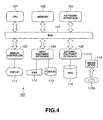
- Fig.4 schematically illustrates an exemplary structure of the hardware of the host computer 100.
- the respective components of the computer 100 will be hereinafter explained in detail.
- a CPU (central processing unit) 101 as a main controller of the system 100, is configured for executing various applications under control by an operating system (OS).
- OS operating system
- the OS furnishes a GUI (graphical user interface) environment.
- GUI graphical user interface
- the OS may be Windows98/NT of Microsoft Inc., USA.
- the CPU 101 is connected over bus 107 to other equipment, not shown.
- the respective equipment on the bus 107 are afforded with unique memory addresses or I/O addresses, so that the CPU 101 is able to access the equipment based on these addresses.
- the bus 107 is a common signal transmission path, including data, address and control buses, and may be typified by a PCI (Peripheral Component Interconnect) bus.
- PCI Peripheral Component Interconnect
- a memory 102 is used for storage of program codes executed on the CPU 101 or transient storage of current operating data. It should be noted that the memory 102 shown may be a non-volatile memory or a volatile memory, as desired.
- Adisplay controller 103 is a dedicated controller for actually processing drawing commands issued by the CPU 101, and supports the bitmap drawing function equivalent to, for example, SVGA (Super Video Graphic Arrays) or XGA (eXtended Graphic Array).
- the drawing data, processed by the display controller 103 is transiently written in a frame buffer, not shown, and subsequently output to a display device 111, which display device 111 may, for example, be a CRT (Cathode Ray Tube) display or a liquid crystal display.
- CTR Cathode Ray Tube
- An input equipment interface 104 is a device for connecting user input equipment, such as keyboard 112 or mouse 113, to the system 100.
- the input equipment interface 104 is responsive to a coordinate command input through key input from a keyboard 112 or a mouse 113 to produce interrupt in the CPU 101.
- a network interface 105 is able to connect the system 100 to a network, such as LAN (Local Area network), or to a proximity radio data communication, such as Bluetooth or 11B, in accordance with a preset communication protocol, such as Ethernet.
- the network interface 105 is furnished in general in a form of a LAN adapter card, and is used as it is loaded in a PCI bus slot on a motherboard, not shown.
- the host computer 100 is interconnected to the robot 1 via radio data communication or a network.
- the computer 100 may also be connected to the robot 1 by other suitable communication means or data movement means.
- data exchange or movement may also be performed using a recording medium, such as memory cards (memory stick).
- plural host computers are interconnected in a transparent state to form a distributed computer environment.
- software programs or data are distributed.
- the authoring tool of the instant embodiment and the movement sequence program for robots, prepared and edited by the present authoring tool, or even the action files, motion files, sound files or LED operation files, as the movement files, may be distributed over the network.
- the network distribution service of these programs/data may be rendered either for pay or free of charge.
- An external equipment interface 106 is a device for connecting an external device, such as a hard disc drive (HDD) 114 or a media drive 115, to the system 100.
- the external equipment interface 106 is designed so as to comply with interface standards, such as IDE (Integrated Drive Electronics) or SCSI (Small Computer System Interface).
- the HDD114 is an external storage device, well-known per se, having a magnetic disc as a storage medium loaded thereon permanently, and is superior to other external storage devices as to storage capacity and data transfer rate.
- the mounting of a software program on the HDD 116 in an executable state is termed installation of the program on a system.
- program codes of the operating system to be executed by the CPU 101, application programs or device drivers are stored in a non-volatile fashion.
- the authoring tool of the instant embodiment, or the movement sequence program, prepared and edited using the authoring tool may be installed on the HDD 114.
- a media drive 115 is a device in which a CD (Compact Disc), MO ( magneto-optical disc) or a DVD (Digital Versatile Disc) is loaded for accessing the data recording surface.
- a portable medium 115a is used for backup mainly of software programs or data files in a computer readable data form or for moving the data between different systems, such as selling, circulating or distributing the data.
- the authoring tool of the instant embodiment and the movement sequence program for robots, prepared and edited by the present authoring tool, or even the action files, motion files, sound files or LED operation files may be physically circulated or distributed between different equipment, using the portable medium 115a.
- an example of the host computer 100 is a computer compatible with or inheriting a personal computer "PC/AT (Personal Computer/Advanced Technology)" manufactured by IBM of USA.
- PC/AT Personal Computer/Advanced Technology
- IBM IBM of USA.
- computer systems equipped with other architectures may be used as the host computer 100 of the instant embodiment.
- the movement control program comprised of a series of command/data, stating a preset movement pattern of the robot 1, may be created and edited, using an authoring tool booted on the computer 100.
- the movement control program, prepared and edited using this authoring tool may be transferred to the robot 1, using radio communication means, such as Bluetooth or 11B, to execute debugging by concerted operation between the host computer 100 and the robot 1.
- radio communication means such as Bluetooth or 11B
- the authoring system for supporting the creation and editing of the movement control program is constructed by organic linkage between the host computer 100 and the robot 1.
- Fig.5 schematically shows the overall structure of the authoring system.
- the user is able to prepare and edit a prescribed scenario for the mobile robot 1, by a mouse operation, using the GUI picture presented by the authoring tool.
- the GUI picture for preparing the scenario and the editing operation on the GUI picture will be explained in detail subsequently.
- the user is able to create and edit the movement control program for the robot 1, in a script form, such as a high grade language system, e.g., C-language, using a routine text editor etc.
- the authoring tool converts the scenario, prepared and edited by the user on the GUI picture, or the movement control program of the script style, prepared and edited on the text editor, into an assembler-like pneumonic code, termed "RCODE".
- the RCODE means a program language, formulated to control the robot 1 by simple commands. Since the RCODE also has a basic control structure, such as "IF” or "GO", it may also be used as a the lowest level script language for robot control.
- the RCODE movement control program created and edited on the side host computer 100, may be moved to the robot 1 using e.g., a storage medium, such as memory stick.
- a storage medium such as memory stick.
- the RCODE program is taken out row by row and encrypted so as to be sequentially transferred to the robot 1, using radio communication means, such as Bluetooth or 11B.
- the robot 1 on the other hand, is provided with an interpreter/debugger, middleware, driver and an operating system (OS), as an environment for execution and debugging of the movement control program, stated in the RCODE etc.
- OS operating system
- the interpreter is a high level language program for reading-in, row-by-row, the program stated in the RCODE form, for executing the so read-in program. It should be noted that, when the RCODE program in the encrypted form is transmitted from the side host computer 100, as in debugging, it is necessary for an interpreter to decode it transiently before proceeding to interpretation and execution.
- the debugger is a program for finding and correcting errors (bugs) in the RCODE program. That is, a debugger is able to halt the program running at a specified row or to refer to the contents of the memory or the variable at such time.
- the middleware is a set of software modules furnishing basic functions of the robot 1.
- the structure of each module is affected by mechanical and electrical properties of the robot 1, or hardware attributes, such as specifications or shape.
- the middleware is classified into the middleware of the recognition system and that of the output system.
- the middleware of the recognition system is an engine for receiving and processing crude data from the hardware, such as picture or speech data or detection data obtained from other types of the sensor, through a virtual robot. That is, the middleware of the recognition system performs speech or color recognition or detection of distance, orientation, contact, motion or color to acquire the results of recognition, which are notified to an upper application layer, that is a movement control program.
- the middleware of the output system furnishes the functions, such as reproduction of the walking and movements, synthesis of output sound or control of the turning on/off of LED indicators. That is, the middleware of the output system receives behavioral schedules, mapped out on the application layer, to generate the servo control values of the robot, output sound, output light (LED) or output speech, on the joint basis, from one function of the robot 1 to the next, to realize the various actual performances on the robot 1.
- the driver is a program code for performing operations of the respective joint actuators and other hardware operations.
- the middleware and the driver are implemented by the object oriented programs.
- the object orientation based software is handled in terms of a module termed an 'object' which basically is data and a processing sequence for the data, unified together.
- One software is completed by preparing or combining plural objects as necessary.
- the object oriented programming is felt to help improve software development and maintenance.
- An operating system exercises control of data communication between these objects and of execution of other programs.
- the OS is also implemented by an object oriented program.
- the movement scenario created using the authoring tool of the instant embodiment, is made up of creation and editing of the 'behavior' and creation and editing of the 'action', with the resultant product being termed a 'project'.
- this project is set the configuration or CPC (configured peripheral component) of the mobile robot 1, that is the hardware constituent information, comprised of the combination of the trunk, head and legs of the mobile robot 1.
- the project is made up of the behavior file, action file, motion file, sound file and LED operation file.
- the behavior is composed of combination of actions.
- Each action is made up of respective contents, such as motion, sound and the LED operations.
- the motion file is a file which prescribes the movements of the respective joint actuators of the mobile robot 1.
- the motion is prescribed by chronologically arranging two or more key frames delineating the mobile robot 1 striking a pose on a GUI editing picture. The motion editing operation on the GUI editing picture will be explained later in detail.
- the sound file is acoustic data for speech outputting via loudspeaker 17, and is constructed e.g., as MIDI (Musical Instrumental Digital Interface) or WAVE form file.
- MIDI Musical Instrumental Digital Interface
- WAVE Wideband Image File
- the acoustic file stated in the MIDI form, is designed to represent music not as the information of the sound itself, but on converting the performance information, such as loudness, length, timbre or effect into numerical data.
- the numerical data of the MIDI form, constituting the sound are acted on through the GUI editing picture for editing the performance information, as will be explained subsequently in detail.
- the LED movement file is data for prescribing the combination of the turning on/off of the plural LED indicators 19, and is used for forming facial expressions.
- the LED operation file is stated in the MIDI form, and is designed to be edited in desired manner through the GUI editing picture. The editing operation of the GUI editing picture will be explained in detail subsequently.
- the motion, sound and the LED operations represent constituent elements of an action, and are chronological data changing with lapse of time. For accurate reproduction of an action, these constituent elements must be temporally synchronized with one another.
- each file can be edited so that the motion and the sound as well as the turning on/off of the plural LEDs will be synchronized with one another on the time axis, as will be explained in detail subsequently.
- An action is constructed by unifying the respective contents, that is the motion file, sound file and the turning on/off of the plural LEDs.
- One action file is a command reproduced in approximately ten seconds, and is also termed 'semantics'.
- action edition in which time lines are utilized on the GUI editing picture to achieve the synchronization between the respective contents with much ease, as will be explained subsequently.
- the respective contents can not only be processed as individual data, but may be handled as an action, that is in a form unified with other contents.
- the behavior is a file prescribing the behavior of the mobile robot 1 and which is constituted by arraying two or more commands, that is actions. An action is reproduced in one direction from the beginning until the end. Conversely, with the behavior, the action reproducing sequence can be prescribed.
- subroutines may also be defined by branching based on conditions or probability or by forming plural commands or actions into a box. Thus, with the behavior, it is possible to state a higher and more complex movement sequence of the mobile robot 1 than with the action.
- Fig.29 schematically shows a functional structure of the authoring system.
- the authoring system of the present embodiment, shown therein, is particularly designed for editing an action, and is made up by an action editor, a keyframe editor, a motion editor, a sound editor, an LED movement editor and a user interface controller for achieving the editing operation by the user with these functional modules by dialog on the GUI picture.
- the action editor is a functional module for editing the motion file, the sound file and the LED movement file with synchronization on the time axis.
- the action editor presents, through the user interface controller, the joint movement (motion) along the time axis of the mobile robot 1, and an action editing window, for setting the timing of the sound and the LED operations, to the user.
- the action editing window including an editing area, made up by a time-line style table for setting the various files on the time axis, will be explained in detail subsequently.
- the keyframe editor is a functional module for editing a keyframe, that is a picture frame delineating a pose of the mobile robot performing a motion at a relevant time point.
- the key frame editor is invoked responsive to the user's actuation on the action editor and accepts the editing operation by the user through a keyframe channel opened on the action editing window.
- the keyframe channel in which thumbnails representing the keyframe are placed at relevant positions on the time axis, will be explained im detail subsequently.
- the motion editor is a functional module for editing the motion, that is chronological movements of the respective joint actuators making up the mobile robot.
- the motion editor is invoked responsive to the user's actuation on the action editor and accepts the editing operation by the user through a motion channel opened on the action editing window.
- the motion channel in which each timing chart stating the chronological movements of the respective joint actuators is listed up (in a tree-view) in a living body simulating model, will be explained in detail subsequently.
- the motion editor presents, through the user interfacing unit, the pose window for editing the pose of the mobile robot 1 on a 3D display screen, and a motion previewer, for pre-viewing the finished motion, to the user.
- the pose window and the motion previewer will be explained in detail subsequently.
- the sound editor is a functional module for setting details of the sound as one of the constituent elements of an action.
- the sound is treated in the MIDI or WAVE form.
- the sound editor presents to the user the sound detail window, usable for setting details of the sound along the time axis, through user interface controller.
- the sound detail window includes an editing area, comprised of a two-dimensional time-line style table, made up by a time axis in the horizontal direction and by a channel in the vertical direction.
- the sound detail window will be explained later in detail.
- the contents as set on the sound detail window are used for demonstration on a sound channel, as later explained, within the action editing window.
- the LED movement editor is a functional module for setting details of the LED operation as one of the constituent elements of the action.
- the LED movement is treated in the MIDI style.
- the LED movement editor presents, through the user interface controller, an LED detail window usable for setting details of the LED movements along the time axis, to the user.
- the LED detail window including an editing area, comprised of a two-dimensional time-line style table, made up by a time axis in the horizontal direction and by a channel in the vertical direction, will be explained subsequently.
- the contents as set on the LED detail window are used for demonstration on an LED movement channel, as later explained, within the action editing window.
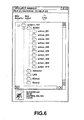
- the user interface controller presents a project window to the user.
- the user interface controller is responsive to the user command, input through each editing window, to access each file system or database supervising the behavior file, action file, motion file, sound file and the LED movement file.
- the project window includes a title bar, a menu bar, a tool bar and a list display area.
- the project window is formed e.g., by an SDI (Single Document Interface) main window.
- the SDI is a user interface of the type operating for opening one document in one window.
- a list of files namely the behavior file, action file, motion file, sound file and the LED movement file, used for editing the behavior and the action, is displayed in a tree style in the project window.
- the project window has the function of displaying the detailed information concerning the item as selected on the tree list.
- the detailed information concerning the behavior includes thumbnails, filenames, items of classification, epitomized description of operation and operating time.
- the detailed information concerning the action includes the thumbnail (initial pose), filename, operating time, initial pose, end pose or the file capacity.
- the detailed information concerning the motion includes the thumbnail (initial pose), filename, operating time, initial pose, end pose and the file capacity.
- the detailed information concerning the sound includes the thumbnail (icon representing the sound), filename, operating time and the file capacity.
- the detailed information concerning the LED operation includes the thumbnail (icon representing the sound), filename, operating time and the file capacity.
- menu bar including menus 'file', 'edit', 'material' and 'help'.
- a pull-down menu made up of respective sub-menus 'new project', 'open project', 'save project', 'save new project' and 'end', appears (see Fig.7).
- the pre-existing project file is opened. If the unsaved project is already opened, a dialog appears to prompt the user to confirm whether or not the project is to be saved, in the manner as described above.
- the relevant project file is overwrite-saved. If the file has not been saved, a file setting dialog, as later explained, appears, as in saving a new project, to prompt the user to input the filename.
- a file setting dialog appears to prompt the user to input the filename.
- this project window is closed. If the project file in the window has not been saved, a dialog appears to prompt the user whether or not this is to be saved.
- a pull-down menu made up of sub-menus 'create new behavior', 'create new action', 'read-in material' and 'delete material' appears (see Fig.8).
- the behavior editing window is opened in a novel state. This behavior is automatically added to the list of the behavior in the project window.
- the behavior editing is not directly related to the purport of the present invention and hence is not explained in further detail herein.
- the action editing window 200 is opened in a novel state. This action is automatically added to the list of the actions in the project window.
- the menu 'help' includes sub-menus such as topic, support web or version information.
- the create new behavior button is equivalent to the sub-menu 'create new behavior' in the menu 'material'.
- the create new action button is equivalent to the sub-menu 'create new action' in the menu 'material'.
- the trash is equivalent to the sub-menu 'delete material' in the menu 'material'.
- the so-called drag-and-drop operation is allowed. That is, a file icon on the explorer may be dragged to an optional site of the tree for direct registration.
- the material on the tree list can be dragged to any desired editing window.
- the action can be dragged to the behavior window, whilst the motion, sound and LED operations can be dragged tot the action window.
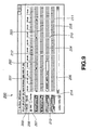
- Fig.9 schematically shows the structure of an action editing window 200.
- the timings of the joint movement (motion) and the those of the sound and LED operations of the mobile robot 1 along time axis may be set.
- the results of editing on the editing window are saved as action files having the extension "act".
- the action editing windows 200 may be adapted to be switched responsive to the model selection operations by the user.
- the action editing window 200 is made up of a title bar, a menu bar and an editing area for setting the motion data, sound data and the LED operation data on the time axis.
- menus 'file', 'material' and 'help' are provided in the menu bar.
- a pre-existing action file is opened. If an unsaved action has already been opened, there appears a dialog prompting the user to confirm whether or not the action is to be saved.
- the relevant action file is overwrite-saved.
- a file setting dialog appears, as in the case of new action saving, as later explained, to prompt the user to input the filename.
- a file setting dialog appears to prompt the user to input a filename.
- the action file edited on the action editing window 200, shown in Fig.9, is transferred to the actual machine, that is to the mobile robot 1, to really reproduce the file by way of a trial.
- the action file may be transferred to the mobile robot 1 via near radio data communication, such as Bluetooth, or moved between devices through the intermediary of a medium, such as a memory card.
- this action editing window 200 is closed. If an action file(s) in the window is as yet not saved, a dialog appears to prompt the user to confirm whether or not this file is to be saved.
- the motion over a selected time span, if any, is cut, whereas, if there is no such time span, the motion, sound and the LED operations of the frame in question, are cut.
- the so cut data is transiently stored in a clipboard.
- the motion over a selected time span, if any, is cut.
- the so cut data is transiently stored in a clipboard.
- the sound over a selected time span, if any, is cut. Actually, the so cut data is transiently stored in a clipboard.
- the LED operation over a selected time span, if any, is copied.
- the so copied data is transiently stored in a clipboard.
- the motion over a selected time span, if any, is deleted, whereas, if there is no such time span, the motion, sound and the LED operation, that is the action, of the frame in question is deleted.
- the frame of the current time point is formed into a key frame. That is, a pose can be generated on interpolation between pre-existing keyframes and formed into new keyframe data.
- the frame(s) for a selected time span, if any, is inserted at the current time point.
- the overall time of the action is elongated by the specified frame time period.
- the frame(s) corresponding to a selected time span, if any, is deleted from the current time point. At this time, frames lying towards left in the editing area are padded. As a result of the frame deletion, the overall time of the action is shorter by the time corresponding to the deleted frames.
- the sub-menu 'delete specified frames' is selected, there appears a numerically input dialog to delete the frames corresponding to the numerical figure input on the dialog.
- the numerical figures as input are time-specifying figures. At this time, frames lying towards left in the editing area are padded. As a result of the frame deletion, the overall time of the action is shorter by the time corresponding specified frame time.
- the motion file is read-in from the specified site of storage, such as local disc, so as to be inserted at the current time point on a motion channel 203 in the editing area as later explained.
- the keyframe included in the motion file directly becomes a keyframe.
- the motion of the selected time span is stored as the motion file in the site of storage specified, such as local disc.
- the sound file is read-in from the site of storage as specified, such as local disc, and is inserted at the current time point on a sound channel 204 in the editing area.
- the sound of the specified time span is stored as a sound file of, for example, the MIDI style, in the specified storage site, such as local disc.
- the LED operating file is read-in from the site of storage as specified, such as local disc, and is inserted at the current time point on an LED channel in the editing area, as later explained.
- the sound of the specified time span is stored as an LED file of, for example, the MIDI style, in the specified storage site, such as local disc.
- sub-menus such as topics, support webs and the version information.
- the editing area in the action editing window 200 is a two-dimensional time line style table comprised of the time axis in the horizontal direction and the channel in the vertical direction.
- the time line table there are a time ruler 201, a keyframe channel 202, a motion channel 203, a sound channel 204 and an LED operation channel 205.
- real-time display can be switched to display of the number of frames, and vice versa, using a unit switching radio button 207.
- real-time display is selected.
- the real-time display is graduated in seconds and milliseconds, each being of two digits.
- the relationship between display in real-time display and display on the time ruler 201 is shown by the following equation 1:
- the number of frames is in four digits.
- the maximum number of frames of 9999 is approximately 160 seconds.
- the possible display time in seconds means an approximate number of seconds for the maximized window size in a display in SVGA(Super Video Graphic Array).
- the time ruler 201 includes an end time display field 208 and a current time display field 209, in addition to the unit switching radio button 207.
- a time representing numerical value, indicating the end time of an action being edited, that is the operating time, is displayed (in the illustrated example,"09:40" ( 9 seconds 40), is displayed).
- an 'initial pose specifying popup menu' not shown, for specifying the initial pose
- a 'final pose specifying popup menu' not shown, for specifying the final pose
- the 'time width changing popup menu' again not shown, for changing the interval of the time ruler 201
- a 'keyframe line 210' an 'end time line 211' and a 'current time line 212' are displayed.
- a keyframe line 210 indicating the time of keyframes 202a to 202b, as later explained, is displayed as intersecting the respective channels.
- the user is able to continue the editing operation as the or she checks for synchronization between the motion, sound and the LED operations.
- the end time line 211 indicating the end time of an action being edited, is displayed as intersecting the respective channels, the user is able to visually grasp the time range being edited.
- the end time line 211 may be grasped as the final pose keyframe line.
- the current time line 212 indicating the current time, is displayed as intersecting the respective channels. Basically, when any one channel is clicked, the current time is moved to such clicked position.
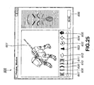
- a three-dimensional image of the mobile robot 1 at the current time is displayed at all times.
- This three-dimensional image is obtained by the authoring system automatically generating an interpolated frame for the current time and carrying out picture processing, such as coordinate transformation, based on e.g., the movements of the respective joint actuators.
- the keyframe channel 202 is an area in which to display the keyframe along the time axis prescribed by the time ruler 201.
- the keyframe channel 202 can be opened or closed as desired.
- Fig.13 shows the action editing window 200 as the keyframe channel 202 is opened (keyframe detail channel).
- a thumbnail representing a key frame.
- the 'keyframe' here means a picture frame delineating the pose at the relevant time of the mobile robot effectuating the motion.
- the initial pose and the final pose means special keyframes at the beginning and trailing ends of a keyframe channel.
- the first and last keyframes are put from the outset.
- interpolated frame a frame interpolated by the keyframes on both sides of this time interval, referred to below as interpolated frame.
- the interpolated frame is not displayed on the keyframe.
- Each keyframe is arranged on the keyframe channel so that the left end of the thumbnail will be the time point of the keyframe. Moreover, the thumbnail can be dragged in the left and right direction along the time axis, the keyframe line then performing the followup movement to change the time of the corresponding keyframe. It is noted that the extension and contraction of the keyframe of the last pose is the extension and contraction of the overall action time.
- the pose editing window of the relevant pose is opened to enable the pose editing. It should be noted that the initial and trailing poses are not editable such that double-clicking these poses cannot open the pose editing window.
- the pose editing window will be explained in detail subsequently.
- the motion channel 203 is an area for editing and displaying the motion contents along the time axis prescribed by the time ruler 201.
- the motion channel 203 may be opened and closed.
- Fig.14 shows the action editing window 200, with the motion channel 203 opened (motion detail channel).
- the motion is defined by the movements of the respective joint actuators forming the mobile robot 1.
- the timing charts stating the chronological movements of the respective joint actuators are listed up in a tree style in accordance with the living body simulating model (tree view).
- the segmented line graphs of the respective timing charts represent time changes of movements, that is rotational angles, of the relevant joint actuators.
- the setting values at the relevant time of the relevant joint actuators can be changed by vertically dragging the points of intersection of the keyframe line 210 and the segmented line. Moreover, the dragging changes the poses corresponding to the keyframe line 210 to enable the automatic updating of the keyframe contents.
- each joint actuator can be visually grasped in the timing chart style.
- the segmented line can be directly acted on by drag-and-drop.
- a segmented line concerning a given joint actuator can be copied to another joint actuator.
- the motion file editing operation can be performed intuitively, while the labor in the editing operation can be saved appreciably.
- regular movements such as movements symmetrical in the left and right direction, may be edited extremely readily.
- motion data of a given motion differs depending on the difference of the model of the mobile robot 1, that is the difference in the information in the hardware structure ascribable to different combinations of the CPC components.
- the data can be re-used as data for different models by applying data transformation on the basis of the model-based fixed data.
- the motion detail channel and its tree view are scrolled horizontally and vertically in keeping with the operation of the scroll bar for the horizontal direction and that for the vertical direction.
- the sound channel is an area for displaying sound data along the time axis prescribed by the time ruler 201.
- the 'sound detail window' independent from the action editing window 200 may be opened to edit the sound data of the MIDI style on the window by GUI operation.
- the sound detail window will be explained in detail subsequently.
- the sound channel 204 is provided with a sound ON/OFF check box 213. By marking the check box, the sound may be issued in reproduction.
- the LED operation channel 205 is an area in which to display LED operating data along the tine axis prescribed by the time ruler 201.
- an 'LED detail window 500' independent from the action editing window 200 may be opened to edit the LED operating data of the MIDI style on the window by GUI operation.
- the LED detail window 500 will be explained later in detail.
- the LED operating channel 205 is provided with an LED ON/OFF check box 214. By marking the check box, the LED operation may be energized in reproduction.
- the action editing window 200 is able to accept the drag-and-drop operation from the project window (see Fig.6). That is, the respective files, as constituent elements of an action, such as motion file, sound file or the LED file, can be directly dragged and dropped from the project window for registration in the action window extremely readily.
- the action editing window 200 is also able to accept the drag-and-drop operation from the MS Windows explorer. That is, the respective files, as constituent elements of an action, such as motion file, sound file or the LED file, can be directly dragged and dropped from the explorer window for registration in the action window extremely readily.
- the files registered in the action window are simultaneously registered in the project window.
- Fig.15 schematically shows the structure of a sound detail window 300 used for editing the sound file of the MIDI style.
- the sound detail window 300 is made up by a title bar, a menu bar and an editing area in which to execute the editing of the sound file of the MIDI style by GUI operations.
- menu bar there are provided respective menus 'file', 'edit', 'set' and 'help'.
- a novel MIDI sound is produced. If already an unsaved MIDI sound is opened, there appears a dialog prompting the user to confirm whether or not the MIDI sound is to be saved.
- a pre-existing MINI sound file is opened. If an unsaved MIDI sound has already been opened, there appears a dialog prompting the user to confirm whether or not the action is to be saved (see the same figure).
- the relevant action file is overwrite-saved.
- a file setting dialog appears, as in the case of new action saving, as later explained, to prompt the user to input the filename.
- a file setting dialog appears to prompt the user to input a filename.
- the sound detail window 300 is closed. If the sound file in the window is not as yet saved, there appears a dialog prompting the user to confirm whether or not the unsaved file is to be saved.
- the sound over a selected time span, if any, is cut.
- the so cut data is transiently stored in a clipboard. By this cutting, not the frame itself but the information concerning the contents of the frame is lost.
- the sound over a selected time span, if any, is cut. Actually, the so cut data is transiently stored in a clipboard.
- the motion over a selected time span, if any, is deleted. It is not the frame itself but the information on the contents of the frame that is lost.
- the sub-menu 'length of a quarter note' further has a sub-menu, not shown, and can be subdivided only for one fourths of the note.
- the length so set is displayed as a grid on the score along the time axis direction.
- the sub-menu 'meter' further has a sub-menu specifying the rhythm. Based on the value, here set, there is delineated a line determining the meter on the time axis grid on the score.
- the editing area is a two-dimensional time-line table, formed by the time axis in the transverse direction and by the channel in the vertical direction.
- the time line table is made up by a time ruler 301, a keyframe channel 302, a score channel 303 and a velocity channel 304.
- the time ruler 301 exploits a unit switching radio button 305 to switch between real time display and the display with the number of frames.
- real-time display is selected.
- the real-time display is in second: millisecond, each being of two digits.
- the time ruler 301 with display with the number of frames is graduated so that the number of frames is represented by four digits.
- the maximum number 9999 of frames is equivalent to approximately 160 seconds.
- the time ruler 301 includes an end time display field 306 and a current time display field 307, in addition to the unit switching radio button 305.
- These fields are editable text fields. When a numerical figure for any meaningful time point is input, it becomes the end time such that the last keyframe is moved or the current time is moved to such position.
- a 'time width changing popup menu' not shown, for changing the interval of the time ruler 301, may be invoked.
- a 'keyframe line 308', an 'end time line 309' and a 'current time line' 310 are displayed as time display lines.
- the keyframe line 308, representing the time of each keyframe, as later explained, is demonstrated as intersecting the respective channels.
- the user is able to perform the operation of editing the MIDI sound as the or she visually checks for synchronization with the keyframe.
- the end time line 309 indicating the end time of the action being edited is displayed as intersecting the respective channels, the user is able to visually comprehend the time range for editing.
- the current time line 310, indicating the current time is displayed as intersecting the respective channels. Basically, when any optional channel is clicked, the current time shifts to such position.
- keyframe channel 302 keyframe positions, as acquired from the action editing window 200 along time axis as specified by the time ruler 301, are displayed.
- the keyframe channel cannot be opened nor closed within the sound detail window 300.
- the score channel is an area for editing the MIDI sound by GUI operation, and is made up by a piano keyboard and a basic grid along the time axis direction. It should be noted that the effective sound range differs depending on the model of the mobile robot 1.
- the maximum sound range allowed by the hardware specifications of the mobile robot 1 is demonstrated by image display of the piano keyboard.
- the reproducible sound range may be displayed brightly, with the remaining areas being displayed in gray.
- the pitch of the absolute sound such as C3 or C4, is displayed.
- the grid of time width of the quarter note as set is displayed.
- the lines of the two grids, that is two beats, three grids, that is three beats, or four grids, that is four beats are emphasized.
- a score is formed by the sound duration as the basis of the time axis and by the pitch of piano keys.
- One mesh is termed a cell.
- the cell with the sound is colored.
- no sound can be put in the different scales on the same time axis.
- a void, that is uncolored, cell is clicked, the sound of a duration of the sound note mark as selected is put. If the sound is present at another pitch position at the same time, the sound is replaced by the clicked pitch. If the cell where the sound is already present is clicked, the sound is removed.
- the velocity channel 304 is an area for demonstrating the intensity of the velocity from one sound to another.
- Fig.15 shows the sound intensity in a bar graph, it may also be shown by a segmented line graph.
- the sound intensity at each nodal point can be adjusted by dragging the upper end of each bar in the bar graph.
- the maximum sound volume is set as default.
- a 'replay button' for commanding the replay of the edited sound may also be provided in the sound detail channel.
- Fig.19 schematically shows the structure of a sound detail window 400 for displaying the sound file of the WAVE form.
- the sound detail window 400 is made up of a title bar, a menu bar and an editing area for editing the sound file of the WAVE form.
- menus 'file', 'edit' and 'help' are provided in the menu bar.
- the pre-existing WAVE sound file is opened. If an unsaved sound has already been opened, there appears a dialog prompting the user to confirm whether or not the WAVE sound is to be saved.
- the relevant WAVE sound file is overwrite-saved. If the sub-menu 'save new sound' is selected, a file setting dialog appears to prompt the user to input a filename.
- this sound editing window 400 is closed. If a sound file(s) in the window is as yet not saved, a dialog appears to prompt the user to confirm whether or not this file is to be saved.
- the sound over a selected time span, if any, is cut.
- the so cut data is transiently stored in a clipboard. By this cutting, not the frame itself but the information concerning the contents of the frame is lost.
- the motion over a selected time span, if any, is copied.
- the so copied data is transiently stored in a clipboard.
- the motion over a selected time span, if any, is deleted.
- the frame itself is not lost, but is in a silent state.
- sub-menus such as topic, support web or the version information.
- the editing area of the sound detail window 400 for WAVE sound is two-dimensional time-line table, formed by the time axis in the transverse direction and by the channel in the vertical direction.
- the time line table is made up by a time ruler 401, a keyframe channel 402 and a WAVE channel 403.
- the time ruler 401 exploits a unit switching radio button 404 to switch between real time display and the display with the number of frames.
- real-time display is selected.
- the real-time display is in second: millisecond, each being of two digits.
- the time ruler 401 with display with the number of frames is graduated so that the number of frames is represented by four digits.
- the maximum number 9999 of frames is equivalent to approximately 160 seconds.
- the time ruler 401 includes an end time display field 405 and the current time display field 406, in addition to the unit switching radio button 404.
- a 'time width changing popup menu' not shown, for changing the interval of the time ruler 401, may be invoked.
- a 'keyframe line 407', an 'end time line 408' and a 'current time line 409' are displayed as time display line.
- the keyframe line 407 representing the time of each keyframe, as later explained, is demonstrated as intersecting the respective channels.
- the user is able to perform the operation of editing the MIDI sound as the or she visually checks for synchronization with the keyframe.
- the end time line 408 indicating the end time of the action being edited is displayed as intersecting the respective channels, the user is able to visually comprehend the time range for editing.
- the current time line 409 indicating the current time, is displayed as intersecting the respective channels. Basically, when any optional channel is clicked, the current time shifts to such position.
- keyframe channel 402 keyframe positions, as acquired from the action editing window 200 along time axis as specified by the time ruler 401, are displayed.
- the keyframe channel cannot be opened nor closed within the sound detail window 400.
- the contents of the sound file of the WAVE form are represented as the waveform, as shown in Fig.19.
- the score channel for MIDI style described above, only the basic slicing operation is allowed on the WAVE channel 403.
- a 'replay button' for commanding the replay of the edited sound may also be provided in the sound detail channel.
- Fig.22 schematically shows the structure of a sound detail window 500 used for displaying and editing the LED operation file stated in the MIDI style.
- the sound detail window 500 is made up by a title bar, a menu bar and an editing area in which to execute the editing of the LED operation file of the WAVE style.
- menu bar there are provided respective menus 'file', 'edit', 'set' and 'help'.
- a pre-existing LED operation file is opened. If an unsaved MIDI sound has already been opened, there appears a dialog prompting the user to confirm whether or not its MIDI sound is to be saved (as above).
- the relevant LED operation file is overwrite-saved.
- a file setting dialog appears, as in the case of saving a new LED operation, as later explained, to prompt the user to input the filename.
- a file setting dialog appears to prompt the user to input a filename.
- the LED operation detail window is closed. If the LED operation file in the window is not as yet saved, there appears a dialog to prompt the user to confirm whether or not the unsaved file is to be saved.
- the LED operation over a selected time span, if any, is cut.
- the so cut data is transiently stored in a clipboard.
- the LED operation over a selected time span, if any, is cut.
- the so copied data is transiently stored in a clipboard.
- the LED operation over a selected time span, if any, is deleted. It is not the frame itself but the information on the contents of the frame that is lost.
- sub-menus such as topic, support web or the version information.
- the editing area of the LED detail window 500 is a two-dimensional time-line table, formed by the time axis in the transverse direction and by the channel in the vertical direction.
- the time line table is made up by a time ruler 501, a keyframe channel 502 and a WAVE channel 503.
- the time ruler 501 exploits a unit switching radio button 504 to switch between real time display and the display with the number of frames.
- real-time display is selected.
- the real-time display is in second: millisecond, each being of two digits.
- the time ruler 501 with display with the number of frames is graduated so that the number of frames is represented by four digits.
- the maximum number 9999 of frames is equivalent to approximately 160 seconds.
- the time ruler 501 includes an end time display field 505 and a current time display field 506, in addition to the unit switching radio button 504.
- These fields are editable text fields. When a numerical figure for any meaningful time point is input, it becomes the end time such that the last keyframe is moved or the current time is moved to such position.
- a 'time width changing popup menu' not shown, for changing the interval of the time ruler 501, may be invoked.
- a 'keyframe line 507', an 'end time line 508' and a 'current time line 509' are displayed as time display lines.
- the keyframe line 507 representing the time of each keyframe, as later explained, is demonstrated as intersecting the respective channels.
- the user is able to perform the operation of editing the LED operation as the or she visually checks for synchronization with the keyframe.
- the end time line 508 indicating the end time of the action being edited is displayed as intersecting the respective channels, the user is able to visually comprehend the time range for editing.
- the current time line 509, indicating the current time is displayed as intersecting the respective channels. Basically, when any optional channel is clicked, the current time shifts to such position.
- keyframe channel 502 keyframe positions, as acquired from the action editing window 200 along time axis as specified by the time ruler 501, are displayed.
- the keyframe channel cannot be opened nor closed within the sound detail window 500.
- the score channel is an area for editing the LED operation, stated in the MIDI style, by GUI operations, and is constituted by a list of mounting sites of LEDs on the main body unit of the mobile robot 1, and by a basic grid in the time axis direction.
- LEDs are arranged on the forehead, a right eye ⁇ , a left eye ⁇ , aright eye ⁇ , a left eye ⁇ , a right eye ⁇ , a left eye ⁇ , a tail ⁇ and a tail ⁇ .
- the score channel On the score channel, there are formed scores of respective site list by displaying the illuminated state of the LEDs of the respective sites on the time axis.
- One mesh is termed a 'cell'.
- the cells of the positions of lighting of the LEDs on the time axis are colored depending on the color and the lighting intensity.
- the LEDs of the respective sites can be turned on/off independently of one another.
- an LED site visual 510 which graphically represents the respective sites of the LEDs that can be modified.
- the authoring system of the present embodiment includes a preview window 600 for visually confirming the contents of the action edited on the action editing window 200.
- Fig.25 schematically shows the structure of the preview window 600.
- the preview window 600 is made up of a '3D view 601', a 'set of 3D display switching buttons', a 'current time field' 606 and a 'set of replay buttons'.
- the 3D preview 601 is perpetually displayed an image of the three-dimensional mobile robot 1 generated by computer graphics processing.
- the line of sight direction can be moved to change the 'look' of the view by dragging on this view.
- the 3C model can also be designed to be pre-viewed simultaneously from two or more viewing points.
- the view movement is operatively linked to the user's inputting operations on the set of 3D display switching buttons.
- the center of gravity of the 3D model can be set on each key frame to approximate the apparent movement of the 3D model to closer to the movement of an actual machine.
- an LED operation preview area for demonstrating the LED operations.
- this preview area the manner of the turning on/off of the LEDs of the mobile robot 1 is displayed in synchronism with the movements of the mobile robot 1 on the 3D preview 601.
- the set of the set of 3D display switching buttons includes a 'rotational button 602', 'zoom-in zoom-out button 603', a 'pan button' 604 and a 'home position button 605'. The user may click these buttons to change the line of sight direction within the 3D preview 601.
- the rotating mode is set. If then the 3D preview 601 is dragged, the 3D mobile robot 1 in the 3D preview 601 is rotated.
- the 3D preview 601 is in the zoom mode. If then the 3D preview 601 is dragged in the vertical direction, the 3D mobile robot 1 in the 3D preview 601 is zoomed in/out.
- the 3D preview 601 is in the pan mode. If the 3D view 601 then is dragged in the vertical direction and in the left and right direction, the mobile robot 1 in the 3D preview 601 is panned, that is moved at a high speed.
- the three-dimensional display of the mobile robot 1 reverts to a state of view of default, that is to a state of the robot as seen from the line of sight direction.
- the current time field 606 the current time of the contents as displayed on the 3D preview 601 is displayed. In the instance shown, the current time "04:60" is displayed. If any numerical figure meaningful as time is input to ths field, the display on the 3D preview 601 is changed to a frame of the relevant time. The current time position is also relatively visually displayed.
- the set of replay buttons include a 'frame rewind button 607', a 'previous key frame button 608', a 'play/stop button 609', a 'stepwise frame feed button 610', a 'frame feed button 611' and a 'loop replay button 612'.
- the display of the 3D preview 601 reverts to the first frame. If the 'previous key frame button 608' is clicked, the replay of the display on the 3D preview 601 skips from the current position to the directly previous keyframe. If the 'play/stop button 609' is clicked, the replay of the display of the 3D preview 601 is started or stopped (the play/stop button 609 is halted or in operation during play or stop, respectively).
- the 'stepwise frame feed button 610' is valid only during reproduction of the display of the 3D preview 601 and, if the button is clicked, the display is intermittently fed on the frame basis. When the 'frame feed button 611' is clicked, the display of the 3D preview 601 skips to the last frame. When the 'loop replay button 612' is clicked, the 3D preview 601 is displayed in a loop fashion.
- the authoring system of the instant embodiment includes a pose window 700 for editing a three-dimensional pose of the mobile robot 1 by GUI operations consisting essentially in dragging.
- the pose edited on the pose window 700 can be used e.g., as a keyframe making up the motion.
- the pose window 700 can be booted by double-clicking the desired keyframe on the keyframe channel.
- Fig.26 schematically shows the structure of the pose window 700.
- the pose window 700 is made up of an entity specifying area 701, a list specifying area 702, a setting value area 703, a 3D display area 704, a set of 3D display switching buttons 705 and a display switching popup 706.
- a developed plan view of the mobile robot 1 is displayed to permit the user to select the editable sites.
- the so selected sites correspond to the items of list commands and are displayed with emphasis or 'blinked' on the 3D display to switch the contents of the setting value areas.
- the editable sites of the mobile robot 1 and the setting values thereof are displayed as a list. If the user selects a specified site from this list, the relevant site in the entity specifying area 701 is displayed with emphasis. In the 3D display area 704, emphasized display or blinking occurs to switch the contents of the setting value area 703.
- the names of the setting sites, setting values, minimum settable values and maximum settable values of the editable sites are displayed in a list. If the user selects a specified site, its contents are switched.
- the setting values can be directly set on key input in an inputtable field.
- the angular expression is by an arc, with the setting value being varied on dragging a line for selection.
- the full-body image of the mobile robot 1 generated by 3D graphics is delineated along with the terrestrial ground. If the user clicks to select the relevant site from the 3D display, the site can be selected with emphasis. The setting value can be directly switched on dragging the selected site.
- the contents displayed in the 3D display area 704 are operatively linked with the 3D display switching button, such that, on dragging on the view of the 3D display area 704, the 'look' of the view, that is the line of sight direction, can be changed.
- the set of 3D display switching buttons includes a 'rotational button', a 'zoom-in zoom-out button', a 'pan button' and a 'home position button'. The user may click these buttons to change the line of sight direction within the 3D display area 704.
- the rotating mode is set. If then the 3D display area 704 is dragged, the mobile robot 1 in the 3D display area 704 is rotated. If then the zoom-in zoom-out button is clicked, the mode is the zoom mode. If then the 3D display area 704 is dragged in the vertical direction, the mobile robot 1 is zoomed in and out in the 3D display area 704. If then the pan button is clicked, the mode is the pan mode. If the mobile robot 1 then is dragged in the vertical direction and in the left and right direction in the 3D display area 704, the mobile robot 1 in the 3D display area 704 is panned, that is moved at a high speed. If the home position button is clicked, the three-dimensional display of the mobile robot 1 reverts to a state of view of default, that is to a state of the robot as seen from the line of sight direction.
- the a popup menu (not shown, comprised of a front side/ back side/ right lateral side/ left lateral side/ upper side/ bottom side/ 3D is displayed for switching to a view from the direction as selected by menu selection.
- an OK button and a cancel button On the pose window 700, there are provided an OK button and a cancel button. If the OK button is clicked, all editing items in the window are validated to close the window and, if conversely the cancel button is clicked, all editing items are invalidated to close the window, in a well-known manner.
- the pose window 700 can be used not only for editing the pose of the mobile robot 1 on the authoring system, but also for reading in the orientation as taught to the mobile robot 1 on an actual device, that is joint values of the respective joint actuators, into the system for pre-viewing.
- Fig.27 shows a block diagram for illustrating the processing sequence for previewing the contents as directly taught on the actual device on the pose window 700. The operations of the flowchart are hereinafter explained.
- an operator of the mobile robot 1 performs direct teaching, such as by manually holding the trunk or legs on the actual machine to cause the actual machine to strike a pose (step S1).
- the setting values in the editable sites, such as joint actuators, obtained as a result of the direct teaching, are then read-in and transiently saved (step S2).
- the setting values are then transferred to the authoring system (step S3).
- near radio data communication such as Bluetooth
- data transfer may be made between different devices over a recording medium, such as memory stick.
- the authoring system reads-in the setting values of the editable sites (step S4) to open the pose window 700 to update the display contents or picture contents in the entity specifying area 701, list specifying area 702, setting value area 703 3D and in the display area 704 in accordance with the read-in setting values (step S5).
- the authoring system of the present embodiment includes a motion previewer 800 for previewing the motion as edited by the motion channel as explained previously or the motion having the respective poses edited by the pose window as keyframes.
- Fig.28 schematically shows the structure of the motion previewer 800.
- This motion previewer 800 can be opened on double-clicking the motion file displayed in a tree style on the project window.
- the motion can be previewed, while it can also be copied for pasting on the action editing window 200.
- the motion previewer 800 is adapted for displaying a thumbnail of one or more keyframes 801 making up the motion, that is the thumbnail of the poses.
- the keyframes 801 are arrayed e.g., in the chronological order in which the motion is reproduced.
- the keyframes in the motion previewer 800 may be dragged into the action editing window 200. If there are too many keyframes making up the motion in the preview, horizontal scrolling is used.
- the present embodiment is directed to an authoring system for a pet type robot walking on four legs, like a dog, this is not intended to limit the present invention because the present invention can similarly be applied to a two-legged robot such as a humanoid robot or to a mobile robot other than a legged robot.
- the 'multi-joint' as defined in the claim is not limited to a physical apparatus typified in particular by a legged robot .
- the authoring system of the present invention may, of course, be used for creating and editing the operating sequence for an animation employing a character generated by computer graphics.
- an excellent authoring system and method capable of supporting the creation and editing of the sequence of commands and data stating a preset pattern of operations for a robot.
- an excellent authoring system and method capable of supporting the creation and editing of the movement patterns can be supported using a set of components prescribing the operating states of the robot.
- an excellent authoring system and method whereby the component parts of the robot can be arrayed on the computer display to support the creation and editing of the movement pattern.
- chronological data forming the action of the mobile robot such as motion data, sound data or LED operation data
- time axis for display on a time table of a two-dimensional time line style. Consequently, such a working environment may be provided in which creation and editing may be made as the user visually checks for synchronization between respective chronological data to warrant a working environment of efficient and intuitively comprehensible action edition.
- such a tool may be provided in which a multi-joint structure, including a robot first of all, may be handled as a new entertainment.
- the behavior of the multi-joint structure, including a robot in particular can be programmed to formulate contents extremely readily even in the absence of the profound knowledge about computer programming.
- the user owns a tool for expressing a multi-joint structure to expand the world offered by the robot.
- a user is able to execute programming pertaining to the behavioral sequence of a multi-joint structure through GUI operations.
- the programing operations on the GUI picture may be further simplified and improved in efficiency by providing abundant library.
- the operating sequence that is behavior, of a robot, may be constructed by unifying respective contents, that is motion, sound and the LD operations. According to the present invention, such a working environment may be provided which warrants facilitated synchronization between the respective contents by exploiting a time line in an editing picture of these respective contents.
- the contents can not only be processed as individual data but also treated as actions comprised of combinations of different contents.
Landscapes
- Engineering & Computer Science (AREA)
- Physics & Mathematics (AREA)
- General Physics & Mathematics (AREA)
- Automation & Control Theory (AREA)
- Robotics (AREA)
- Mechanical Engineering (AREA)
- Processing Or Creating Images (AREA)
- Numerical Control (AREA)
- Manipulator (AREA)
- Electrophonic Musical Instruments (AREA)
- Toys (AREA)
Abstract
Description
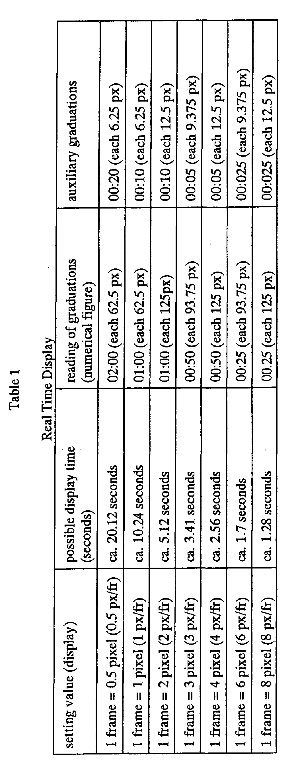
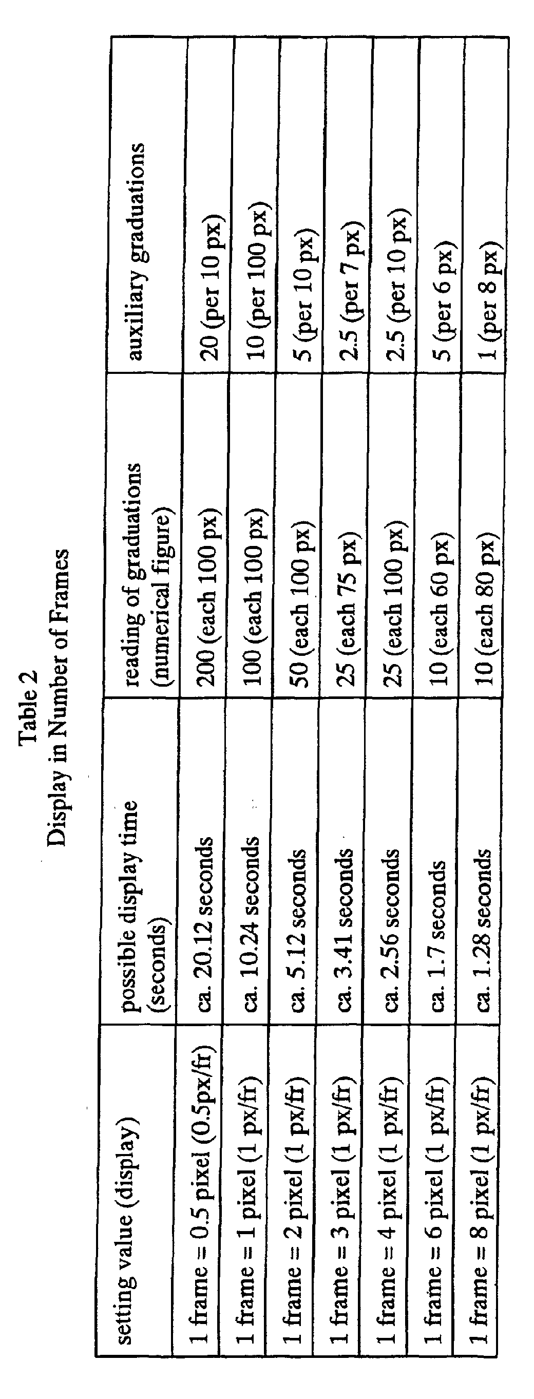
Claims (71)
- An authoring system for supporting the creation and editing of an action of a multi-joint structure comprised of a combination of a plurality of chronological data, comprising:a user inputting unit for inputting commands or data from a user;a user presenting unit for presenting an editing area in which chronological data making up the action are arrayed chronologically along the time axis; anda chronological data editing unit provided for each chronological data making up the action, said chronological data editing unit creating or editing relevant chronological data based on a user input through said user presenting unit.
- The authoring system according to claim 1 wherein one of the chronological data making up the action is motion data stating the chronological movements of respective joints of the multi-joint structure.
- The authoring system according to claim 1 wherein one of the chronological data making up the action is motion data which prescribes chronological movements of respective joints of the multi-joint structure and which, by arraying two or more keyframes each representing the multi-joint structure striking a preset pose on the time axis, smoothly joins the respective keyframes.
- The authoring system according to claim 1 wherein one of the chronological data making up the action is sound data output as sound in timed relation to reproduction of said action.
- The authoring system according to claim 4 wherein the sound data is stated in the MIDI (Musical Instrumental Digital Interface) form or WAVE form.
- The authoring system according to claim 1 wherein one of the chronological data making up the action is indicator display data stating the turning on/off of display indicators displayed in timed relation to reproduction of said action.
- The authoring system according to claim I wherein indicator display data is stated in the MIDI (Musical Instrumental Digital Interface) form.
- The authoring system according to claim 1 wherein the editing area presented by said user presenting unit is comprised of chronological data based chronological data display channels, said data extending along the horizontally arrayed time axis, said channels being arrayed in the vertical direction.
- The authoring system according to claim 8 wherein the editing area presented by said user presenting unit includes a time ruler made up by graduations representing the time axis in real-time.
- The authoring system according to claim 8 wherein the editing area presented by said user presenting unit includes one or more time display lines extending in the vertical direction for indicating the relevant time prescribed by a time ruler.
- The authoring system according to claim 8 wherein the editing area presented by said user presenting unit includes a vertically extending current time display line for indicating the current time on the time axis prescribed by the time ruler;said current time display line being shifted on the time ruler to a position corresponding to user actuation.
- The authoring system according to claim 8 wherein the editing area presented by said user presenting unit includes a display window for previewing movements of the multi-joint structure at the current time.
- The authoring system according to claim 8 wherein one of the chronological data making up the action is motion data which prescribes the chronological movements of respective joints of the multi-joint structure and which arrays two or more keyframes, each representing the multi-joint structure striking a preset pose, to smoothly join the respective keyframes;said editing area presented by said user presenting unit including a keyframe channel representing each keyframe or its thumbnail along the time axis prescribed by said time ruler.
- The authoring system according to claim 13 wherein the keyframe time is changed so as to follow up with dragging of said keyframe or its thumbnail within the keyframe channel.
- The authoring system according to claim 13 wherein a pose editing picture for editing a relevant pose is started responsive to a selecting operation by a user of a keyframe or its thumbnail within the keyframe channel.
- The authoring system according to claim 8 wherein one of the chronological data making up the action is motion data stating the chronological movements of respective joints of the multi-joint structure;the editing area presented by said user presenting unit includes a motion channel for editing and displaying the contents of a motion along the time axis prescribed by the time ruler.
- The authoring system according to claim 16 wherein said motion channel is comprised of respective timing charts representing chronological movements of respective joints of the multi-joint structure, said timing charts being arrayed in the vertical direction.
- The authoring system according to claim 17 wherein the movements of joints at a relevant timing are changed so as to follow up with dragging on the timing chart in said motion channel.
- The authoring system according to claim 8 wherein one of the chronological data making up the action is sound data issued as sound in timed relation to reproduction of an action;the editing area presented by said user presenting unit including a sound channel for indicating the contents of the sound along the time axis prescribed by the time ruler.
- The authoring system according to claim 8 wherein one of the chronological data making up the action is indicator display data stating the operation of the turning on/off of display indicators, as output in timed relation to the reproduction of an action;the editing area presented by said user presenting unit including a display indicator channel for indicating the contents of the indicator data along the time axis prescribed by the time ruler.
- The authoring system according to claim 1 wherein one of the chronological data making up the action is sound data output as sound in timed relation to the reproduction of an action;said user presenting unit further indicating a sound editing area for indicating and editing the sound contents along the time axis prescribed by said time ruler.
- The authoring system according to claim 21 wherein said sound editing area includes a score channel constituted by a basic grid along the time axis direction and a piano keyboard;a score being formed by the sound duration as the reference of the time axis and the pitch of the piano keys;the sound being edited by arraying the color corresponding to sound notes in a cell corresponding to the desired time point and the sound scale.
- The authoring system according to claim 21 wherein said sound editing area includes a velocity channel for representing the intensity of each sound along the time axis.
- The authoring system according to claim 1 wherein one of the chronological data making up an action is indicator data stating the turning on/off of an indicator, output in timed relation to the reproduction of an action;said user presenting unit further indicating an indicator editing area for displaying and editing the contents of indicator data along the time axis prescribed by the time ruler.
- The authoring system according to claim 24 wherein said indicator editing area includes a score channel constituted by a list of sites of arraying of display indicators and by the basic grid along the time axis direction;a score being edited from one site list to another by indicating the turned-on state of the indicator in each site on the time axis on a score channel.
- The authoring system according to claim 1 wherein said user presenting unit further displays a preview window for visually checking an action of the multi-joint structure generated based on each chronological data as edited by the chronological data editing unit.
- The authoring system according to claim 26 wherein one of the chronological data making up an action is motion data stating the chronological movements of the respective joints of the multi-joint structure;said preview window including a 3D view area for three-dimensional display of movements of the multi-joint structure generated based on motion data.
- The authoring system according to claim 26 wherein one of the chronological data making up an action is indicator data stating the turning on/off of an indicator, output in timed relation to the reproduction of an action;said preview window including an indicator operation preview area for displaying the operation of the indicators corresponding to the indicator display data in synchronism with the preview of other chronological data.
- The authoring system according to claim 1 wherein said user presenting unit further displays a pose window for editing the pose of the multi-joint structure by the GUI operation.
- The authoring system according to claim 29 wherein said pose window includes an entity specifying area for displaying the multi-joint structure in a developed plan view for accepting user selection of editable sites.
- The authoring system according to claim 29 wherein said pose window includes a list specifying area for displaying a list of editable sites of the multi-joint structure and setting values thereof.
- The authoring system according to claim 29 wherein said pose window includes a setting value area for displaying a list of the names of setting sites, setting values, settable maximum values and settable minimum values of editable sites of the multi-joint structure.
- The authoring system according to claim 29 wherein said pose window includes a 3D display area for 3D displaying a full image of the multi-joint structure generated by 3D graphics and for accepting user selection on said 3D display.
- The authoring system according to claim 29 further comprising:data inputting means for inputting chronological data making up an action of the multi-joint structure from outside;said pose window displaying the pose generated based on data input from said data inputting means.
- The authoring system according to claim 1 wherein one of the chronological data making up an action is motion data which prescribes chronological movements of respective joints of the multi-joint structure and which arrays two or more keyframes each representing the multi-joint structure striking a preset pose to smoothly join the respective keyframes;said user presenting unit further displaying a motion preview window arraying one or more key frames making up the motion or thumbnails thereof in accordance with the chronological sequence used in motion reproduction.
- An authoring method for supporting the creation and editing of an action of a multi-joint structure comprised of a combination of a plurality of chronological data, comprising:a user presenting step of presenting an editing area in which the chronological data making up the action are arrayed chronologically along the time axis; anda chronological data editing step for creating or editing relevant chronological data based on a user input through the editing area, provided for each chronological data making up the action, via said user presenting step.
- The authoring method according to claim 36 wherein one of the chronological data making up the action is motion data stating the chronological movements of respective joints of the multi-joint structure.
- The authoring method according to claim 36 wherein one of the chronological data making up the action is motion data which prescribes chronological movements of respective joints of the multi-joint structure and which, by arraying two or more keyframes each representing the multi-joint structure striking a preset pose on the time axis, smoothly joins the respective keyframes.
- The authoring method according to claim 36 wherein one of the chronological data making up the action is sound data output as sound in timed relation to reproduction of said action.
- The authoring method according to claim 39 wherein the sound data is stated in the MIDI (Musical Instrumental Digital Interface) form or WAVE form.
- The authoring method according to claim 36 wherein one of the chronological data making up the action is indicator display data stating the turning on/off of display indicators, said display data being displayed in timed relation to reproduction of said action.
- The authoring method according to claim 36 wherein indicator display data is stated in the MIDI (Musical Instrumental Digital Interface) form.
- The authoring method according to claim 36 wherein the editing area presented in said user presenting step is comprised of chronological data based chronological data display channels, said data extending along the horizontally arrayed time axis, said channels being arrayed in the vertical direction.
- The authoring method according to claim 43 wherein the editing area presented in said user presenting step includes a time ruler made up by graduations representing the time axis in real-time.
- The authoring method according to claim 43 wherein the editing area presented by said user presenting step includes one or more time display lines extending in the vertical direction for indicating the relevant time prescribed by a time ruler.
- The authoring method according to claim 43 wherein the editing area presented by said user presenting step includes a vertically extending current time display line for indicating the current time on the time axis prescribed by the time ruler;
there being included a further step of shifting said current time display line on the time ruler to a position corresponding to user actuation. - The authoring method according to claim 43 further comprising a step of presenting a display window for previewing movements of the multi-joint structure at the current time.
- The authoring method according to claim 43 wherein one of the chronological data making up the action is motion data which prescribes the chronological movements of respective joints of the multi-joint structure and which arrays two or more keyframes each representing the multi-joint structure striking a preset pose to smoothly join the respective keyframes;said user presenting step including presenting a key frame channel representing each keyframe or its thumbnail along the time axis prescribed by said time ruler.
- The authoring method according to claim 48 wherein the keyframe time is changed so as to follow up with dragging of said keyframe or its thumbnail within the keyframe channel.
- The authoring method according to claim 48 wherein a pose editing picture for editing a relevant pose is started responsive to a user selecting operation of a keyframe or its thumbnail within the keyframe channel.
- The authoring method according to claim 43 wherein one of the chronological data making up the action is motion data stating the chronological movements of respective joints of the multi-joint structure;said user presenting step including a motion channel for editing and displaying the contents of a motion along the time axis prescribed by the time ruler.
- The authoring method according to claim 51 wherein said user presenting step represents a motion channel by arraying respective timing charts representing chronological movements of respective joints of the multi-joint structure in the vertical direction.
- The authoring method according to claim 52 further comprising a step of changing the movements of joints at a relevant time so as to follow up with dragging on the timing chart in said motion channel.
- The authoring method according to claim 43 wherein one of the chronological data making up the action is sound data issued as sound in timed relation to reproduction of an action;said user presenting step presenting an editing area including a sound channel for indicating the contents of the sound along the time axis prescribed by the time ruler.
- The authoring method according to claim 43 wherein one of the chronological data making up the action is indicator data stating the operation of the turning on/off of the indicator, as output in timed relation to the reproduction of an action;said user presenting step presenting an editing area including a display indicator channel for indicating the contents of the indicator display data along the time axis prescribed by the time ruler.
- The authoring method according to claim 36 wherein one of the chronological data making up the action is sound data output as sound in timed relation to the reproduction of an action;there being further provided a step of indicating a sound editing area for indicating and editing the sound contents along the time axis prescribed by said time ruler.
- The authoring method according to claim 56 wherein said sound editing area includes a score channel constituted by a basic grid along the time axis direction and a piano keyboard;a score being formed by the sound duration as the reference of the time axis and the pitch of the piano keys;the sound being edited by arraying the color corresponding to sound notes in a cell corresponding to the desired time point and the sound scale on said score channel.
- The authoring method according to claim 56 wherein said sound editing area includes a velocity channel for representing the intensity of each sound along the time axis.
- The authoring method according to claim 36 wherein one of the chronological data making up an action is indicator display data stating the turning on/off of a display indicator, output in timed relation to the reproduction of an action;there being further provided a step of indicating an indicator editing area for displaying and editing the contents of indicator data along the time axis prescribed by the time ruler.
- The authoring method according to claim 59 wherein said indicator editing area includes a score channel constituted by a list of arraying sites of the display indicators and by the basic grid along the time axis direction;a score being edited from one site list to another by indicating the turned-on state of the display indicators in respective sites on the time axis on a score channel.
- The authoring method according to claim 36 further comprising a step of displaying a preview window for visually checking an action of the multi-joint structure generated based on each chronological data as edited in the chronological data editing step.
- The authoring method according to claim 61 wherein one of the chronological data making up an action is motion data stating the chronological movements of respective joints of the multi-joint structure;said preview window indicating step three-dimensionally displaying movements of the multi-joint structure, generated based on motion data, in a 3D view area.
- The authoring method according to claim 61 wherein one of the chronological data making up an action is indicator data stating the turning on/off of display indicators, output in timed relation to the reproduction of an action;said preview window indicating step displaying the operation of the display indicators corresponding to the indicator display data in synchronism with the preview of other chronological data.
- The authoring method according to claim 36 further comprising a step of displaying a pose window for editing the pose of the multi-joint structure by the GUI operation.
- The authoring method according to claim 64 wherein said pose window includes an entity specifying area for displaying the multi-joint structure in a developed plan view for accepting user selection of editable sites.
- The authoring method according to claim 64 wherein said pose window includes a list specifying area for displaying a list of editable sites of the multi-joint structure and setting values thereof.
- The authoring method according to claim 64 wherein said pose window includes a setting value area for displaying a list of the names of setting sites, setting values, settable maximum values and settable minimum values of editable sites of the multi-joint structure.
- The authoring method according to claim 64 wherein said pose window includes a 3D display area for 3D displaying a full image of the multi-joint structure generated by 3D graphics and for accepting user selection of said editable sites on said 3D display.
- The authoring method according to claim 64 further comprising a data inputting step of inputting chronological data making up an action of the multi-joint structure from outside;said pose window displaying the pose generated based on data input from said data inputting means.
- The authoring method according to claim 36 wherein one of the chronological data making up an action is motion data which prescribes chronological movements of respective joints of the multi-joint structure and which arrays two or more keyframes each representing the multi-joint structure striking a preset pose to smoothly join the respective keyframes;there being further provided a step of displaying a motion preview window arraying one or more key frames making up the motion or thumbnails thereof in accordance with the chronological sequence used in motion reproduction.
- A recording medium having physically stored thereon, in a computer-readable form, a computer software stating the processing for supporting the creation and editing of an action of a multi-joint structure, comprised of the combination of plural chronological data, on a computer system, said computer software comprising:a user presenting step of presenting an editing area in which chronological data making up the action are arrayed chronologically along the time axis; anda chronological data editing step for creating or editing relevant chronological data based on a user input through an editing area by said user presenting step, said editing area being provided for each chronological data making up the action.
Applications Claiming Priority (3)
| Application Number | Priority Date | Filing Date | Title |
|---|---|---|---|
| JP2000295719A JP4765155B2 (en) | 2000-09-28 | 2000-09-28 | Authoring system, authoring method, and storage medium |
| JP2000295719 | 2000-09-28 | ||
| PCT/JP2001/008602 WO2002026450A1 (en) | 2000-09-28 | 2001-09-28 | Authoring system and authoring method, and storage medium |
Publications (2)
| Publication Number | Publication Date |
|---|---|
| EP1321248A1 true EP1321248A1 (en) | 2003-06-25 |
| EP1321248A4 EP1321248A4 (en) | 2005-10-26 |
Family
ID=18778099
Family Applications (1)
| Application Number | Title | Priority Date | Filing Date |
|---|---|---|---|
| EP01970302A Withdrawn EP1321248A4 (en) | 2000-09-28 | 2001-09-28 | AUTHOR SYSTEM AND AUTHOR METHOD, AND MEMORY MEDIUM |
Country Status (6)
| Country | Link |
|---|---|
| US (1) | US6718231B2 (en) |
| EP (1) | EP1321248A4 (en) |
| JP (1) | JP4765155B2 (en) |
| KR (1) | KR20020056949A (en) |
| CN (1) | CN1392824A (en) |
| WO (1) | WO2002026450A1 (en) |
Cited By (4)
| Publication number | Priority date | Publication date | Assignee | Title |
|---|---|---|---|---|
| WO2012010437A1 (en) * | 2010-07-23 | 2012-01-26 | Aldebaran Robotics | Humanoid robot equipped with a natural dialogue interface, method for controlling the robot and corresponding program |
| EP2168018B1 (en) * | 2007-07-04 | 2012-05-02 | Aldebaran Robotics S.A. | Method of editing movements of a robot |
| WO2012093967A3 (en) * | 2011-01-03 | 2012-11-29 | Katotec Pte. Ltd. (Singapore) | Robot controllers and content files therefor |
| WO2017050895A1 (en) * | 2015-09-23 | 2017-03-30 | Universität Bayreuth | Robot controller |
Families Citing this family (148)
| Publication number | Priority date | Publication date | Assignee | Title |
|---|---|---|---|---|
| US8944070B2 (en) | 1999-04-07 | 2015-02-03 | Intuitive Surgical Operations, Inc. | Non-force reflecting method for providing tool force information to a user of a telesurgical system |
| US20030009664A1 (en) * | 2001-06-28 | 2003-01-09 | Eastman Kodak Company | Method and player for authenticating playback of animated content |
| US7426717B1 (en) * | 2001-11-27 | 2008-09-16 | Adobe Systems Incorporated | System and method for debugging files in a runtime environment |
| JP4194272B2 (en) * | 2001-12-28 | 2008-12-10 | キヤノン株式会社 | Moving image management apparatus and method |
| JP2004001162A (en) * | 2002-03-28 | 2004-01-08 | Fuji Photo Film Co Ltd | Pet robot charging system, receiving arrangement, robot, and robot system |
| JP4081747B2 (en) * | 2002-05-17 | 2008-04-30 | 技研株式会社 | Robot drive control method and apparatus |
| JP3860519B2 (en) * | 2002-09-02 | 2006-12-20 | 株式会社バンダイ | Motor body control system, motor body and program thereof |
| US7024277B2 (en) * | 2002-11-11 | 2006-04-04 | Alfred Schurmann | Determination and control of activities of an emotional system |
| JP2004291174A (en) * | 2003-03-27 | 2004-10-21 | Denso Corp | Robot, robot interaction device and program |
| JP2005046926A (en) * | 2003-07-30 | 2005-02-24 | Toshiba Corp | Service robot system, main robot and driven robot |
| CN100436082C (en) * | 2003-08-12 | 2008-11-26 | 株式会社国际电气通信基础技术研究所 | Control system for communication robot |
| US20050081138A1 (en) * | 2003-09-25 | 2005-04-14 | Voss James S. | Systems and methods for associating an image with a video file in which the image is embedded |
| EP1530138A1 (en) * | 2003-11-10 | 2005-05-11 | Robert Bosch Gmbh | Generic measurement and calibration interface for development of control software |
| JP2005148789A (en) * | 2003-11-11 | 2005-06-09 | Fanuc Ltd | Robot teaching program editing device by voice input |
| JP4244812B2 (en) * | 2004-01-16 | 2009-03-25 | ソニー株式会社 | Action control system and action control method for robot apparatus |
| JP4516344B2 (en) * | 2004-04-12 | 2010-08-04 | 本田技研工業株式会社 | Legged mobile robot |
| WO2006002385A1 (en) * | 2004-06-24 | 2006-01-05 | Irobot Corporation | Programming and diagnostic tool for a mobile robot |
| US7543663B2 (en) | 2004-10-01 | 2009-06-09 | Applied Minds, Inc. | Bimodal conveyance mechanism |
| US7588105B2 (en) * | 2004-10-01 | 2009-09-15 | Applied Minds, Inc. | Virtual-wheeled vehicle |
| US8000837B2 (en) * | 2004-10-05 | 2011-08-16 | J&L Group International, Llc | Programmable load forming system, components thereof, and methods of use |
| US9789608B2 (en) | 2006-06-29 | 2017-10-17 | Intuitive Surgical Operations, Inc. | Synthetic representation of a surgical robot |
| JP2007030060A (en) * | 2005-07-22 | 2007-02-08 | Honda Motor Co Ltd | Mobile robot controller |
| EP1762345A1 (en) * | 2005-09-08 | 2007-03-14 | Asea Brown Boveri Ab | An industrial robot system comprising a control unit and an external computer |
| US20070098281A1 (en) * | 2005-10-31 | 2007-05-03 | International Business Machines Corporation | Damping rotational vibration in a multi-drive tray |
| US8607147B2 (en) * | 2005-12-09 | 2013-12-10 | International Business Machines Corporation | System and methods for previewing alternative compositions and arrangements when composing a strictly-structured flow diagram |
| US20070168975A1 (en) * | 2005-12-13 | 2007-07-19 | Thomas Kessler | Debugger and test tool |
| TWI312992B (en) * | 2005-12-15 | 2009-08-01 | Ind Tech Res Inst | Video disc containing description data structure for displaying a menu and method for selecting an option of the menu from the video disc |
| US20080064927A1 (en) | 2006-06-13 | 2008-03-13 | Intuitive Surgical, Inc. | Minimally invasrive surgery guide tube |
| US9718190B2 (en) | 2006-06-29 | 2017-08-01 | Intuitive Surgical Operations, Inc. | Tool position and identification indicator displayed in a boundary area of a computer display screen |
| US20090192523A1 (en) | 2006-06-29 | 2009-07-30 | Intuitive Surgical, Inc. | Synthetic representation of a surgical instrument |
| US12357400B2 (en) | 2006-06-29 | 2025-07-15 | Intuitive Surgical Operations, Inc. | Synthetic representation of a surgical robot |
| US10008017B2 (en) | 2006-06-29 | 2018-06-26 | Intuitive Surgical Operations, Inc. | Rendering tool information as graphic overlays on displayed images of tools |
| US10258425B2 (en) | 2008-06-27 | 2019-04-16 | Intuitive Surgical Operations, Inc. | Medical robotic system providing an auxiliary view of articulatable instruments extending out of a distal end of an entry guide |
| US20080004749A1 (en) * | 2006-06-30 | 2008-01-03 | Honeywell International, Inc. | System and method for generating instructions for a robot |
| US20080082214A1 (en) * | 2006-10-03 | 2008-04-03 | Sabrina Haskell | Method for animating a robot |
| KR100772175B1 (en) * | 2006-10-23 | 2007-11-01 | 한국전자통신연구원 | Communication method in network robot system and network robot system |
| JP2008206668A (en) * | 2007-02-26 | 2008-09-11 | Taya Engineering Kk | Wireless remote-control model |
| JP2008254074A (en) * | 2007-03-30 | 2008-10-23 | Sega Corp | Robot motion editing apparatus and program thereof |
| US9469034B2 (en) | 2007-06-13 | 2016-10-18 | Intuitive Surgical Operations, Inc. | Method and system for switching modes of a robotic system |
| US8620473B2 (en) | 2007-06-13 | 2013-12-31 | Intuitive Surgical Operations, Inc. | Medical robotic system with coupled control modes |
| US9138129B2 (en) | 2007-06-13 | 2015-09-22 | Intuitive Surgical Operations, Inc. | Method and system for moving a plurality of articulated instruments in tandem back towards an entry guide |
| US9084623B2 (en) | 2009-08-15 | 2015-07-21 | Intuitive Surgical Operations, Inc. | Controller assisted reconfiguration of an articulated instrument during movement into and out of an entry guide |
| US9089256B2 (en) | 2008-06-27 | 2015-07-28 | Intuitive Surgical Operations, Inc. | Medical robotic system providing an auxiliary view including range of motion limitations for articulatable instruments extending out of a distal end of an entry guide |
| JP5181541B2 (en) * | 2007-06-15 | 2013-04-10 | 富士通株式会社 | Robot system, editor terminal, and editor program |
| US8353767B1 (en) * | 2007-07-13 | 2013-01-15 | Ganz | System and method for a virtual character in a virtual world to interact with a user |
| GB0714148D0 (en) * | 2007-07-19 | 2007-08-29 | Lipman Steven | interacting toys |
| US8689139B2 (en) * | 2007-12-21 | 2014-04-01 | Adobe Systems Incorporated | Expandable user interface menu |
| US8864652B2 (en) | 2008-06-27 | 2014-10-21 | Intuitive Surgical Operations, Inc. | Medical robotic system providing computer generated auxiliary views of a camera instrument for controlling the positioning and orienting of its tip |
| US12239396B2 (en) | 2008-06-27 | 2025-03-04 | Intuitive Surgical Operations, Inc. | Medical robotic system providing an auxiliary view including range of motion limitations for articulatable instruments extending out of a distal end of an entry guide |
| CN101650553B (en) * | 2008-08-11 | 2013-04-24 | 悠进机器人股份公司 | Application of robot manufacturing tool for controlling robot and manufacturing robot contents |
| US12266040B2 (en) | 2009-03-31 | 2025-04-01 | Intuitive Surgical Operations, Inc. | Rendering tool information as graphic overlays on displayed images of tools |
| FR2946160B1 (en) * | 2009-05-26 | 2014-05-09 | Aldebaran Robotics | SYSTEM AND METHOD FOR EDIT AND ORDER BEHAVIOR OF MOBILE ROBOT. |
| US8918211B2 (en) | 2010-02-12 | 2014-12-23 | Intuitive Surgical Operations, Inc. | Medical robotic system providing sensory feedback indicating a difference between a commanded state and a preferred pose of an articulated instrument |
| US9492927B2 (en) | 2009-08-15 | 2016-11-15 | Intuitive Surgical Operations, Inc. | Application of force feedback on an input device to urge its operator to command an articulated instrument to a preferred pose |
| KR100968944B1 (en) * | 2009-12-14 | 2010-07-14 | (주) 아이알로봇 | Apparatus and method for synchronizing robot |
| JP5645618B2 (en) * | 2009-12-24 | 2014-12-24 | キヤノン株式会社 | Information processing apparatus, information processing method, and program |
| TWI395153B (en) * | 2009-12-28 | 2013-05-01 | Nat Univ Tsing Hua | Action Mechanism and Generating Method of Mimic - level Digital Model Based on Object Feature |
| US9240066B2 (en) | 2010-03-02 | 2016-01-19 | Kun Yu | Methods and apparatuses for facilitating skeletal animation |
| TWI416289B (en) | 2010-05-28 | 2013-11-21 | Compal Communications Inc | Automatic machine and method for controlling the same |
| CN102279569B (en) * | 2010-06-08 | 2013-05-08 | 华宝通讯股份有限公司 | Action editing system and method for mechanical device |
| CN102279570A (en) * | 2010-06-10 | 2011-12-14 | 华宝通讯股份有限公司 | Robot and control method thereof |
| TWI478798B (en) * | 2010-06-18 | 2015-04-01 | Compal Electronics Inc | Automatic mechanical device and control method thereof |
| US9015093B1 (en) | 2010-10-26 | 2015-04-21 | Michael Lamport Commons | Intelligent control with hierarchical stacked neural networks |
| US8775341B1 (en) | 2010-10-26 | 2014-07-08 | Michael Lamport Commons | Intelligent control with hierarchical stacked neural networks |
| KR101714791B1 (en) * | 2010-12-01 | 2017-03-09 | 한국전자통신연구원 | Apparatus for controlling service of network robot system based on remote procedure calls and method thereof |
| JP5370376B2 (en) * | 2011-01-13 | 2013-12-18 | 横河電機株式会社 | Device information display device, device information display program, and recording medium |
| US9566710B2 (en) | 2011-06-02 | 2017-02-14 | Brain Corporation | Apparatus and methods for operating robotic devices using selective state space training |
| US10104333B2 (en) | 2011-06-02 | 2018-10-16 | Gree, Inc. | Vector data conversion output device, vector data conversion output method, and vector data conversion output program |
| JP5479541B2 (en) * | 2011-08-23 | 2014-04-23 | パナソニック株式会社 | Parallel link robot and its operation teaching method |
| TW201322752A (en) * | 2011-11-17 | 2013-06-01 | Chiuan Yan Technology Co Ltd | Bi-directional synchronous operation displacement device |
| US8843235B2 (en) * | 2012-01-13 | 2014-09-23 | Toyota Motor Engineering & Manufacturing North America, Inc. | Robots, computer program products, and methods for trajectory plan optimization |
| US8988578B2 (en) | 2012-02-03 | 2015-03-24 | Honeywell International Inc. | Mobile computing device with improved image preview functionality |
| US20130215144A1 (en) * | 2012-02-20 | 2013-08-22 | Sony Corporation | Display control device and display control method |
| CN103456150A (en) * | 2012-05-30 | 2013-12-18 | 华硕电脑股份有限公司 | Remote control system and remote control method thereof |
| CN102915755A (en) * | 2012-09-07 | 2013-02-06 | 博康智能网络科技股份有限公司 | Method for extracting moving objects on time axis based on video display |
| JP5582427B2 (en) * | 2012-12-18 | 2014-09-03 | 株式会社安川電機 | Teaching data creation apparatus, robot system, and teaching data creation method |
| US10507066B2 (en) | 2013-02-15 | 2019-12-17 | Intuitive Surgical Operations, Inc. | Providing information of tools by filtering image areas adjacent to or on displayed images of the tools |
| US9764468B2 (en) | 2013-03-15 | 2017-09-19 | Brain Corporation | Adaptive predictor apparatus and methods |
| US20170206064A1 (en) * | 2013-03-15 | 2017-07-20 | JIBO, Inc. | Persistent companion device configuration and deployment platform |
| KR101626966B1 (en) * | 2013-03-22 | 2016-06-02 | 주식회사 케이티 | Apparatus and method for developing robot contents |
| US9495788B2 (en) | 2013-03-22 | 2016-11-15 | Kt Corporation | Apparatus and method for developing robot contents |
| US9242372B2 (en) | 2013-05-31 | 2016-01-26 | Brain Corporation | Adaptive robotic interface apparatus and methods |
| US10262462B2 (en) * | 2014-04-18 | 2019-04-16 | Magic Leap, Inc. | Systems and methods for augmented and virtual reality |
| US9384443B2 (en) | 2013-06-14 | 2016-07-05 | Brain Corporation | Robotic training apparatus and methods |
| US9792546B2 (en) | 2013-06-14 | 2017-10-17 | Brain Corporation | Hierarchical robotic controller apparatus and methods |
| US9314924B1 (en) | 2013-06-14 | 2016-04-19 | Brain Corporation | Predictive robotic controller apparatus and methods |
| US9436909B2 (en) | 2013-06-19 | 2016-09-06 | Brain Corporation | Increased dynamic range artificial neuron network apparatus and methods |
| US9579789B2 (en) | 2013-09-27 | 2017-02-28 | Brain Corporation | Apparatus and methods for training of robotic control arbitration |
| US9296101B2 (en) | 2013-09-27 | 2016-03-29 | Brain Corporation | Robotic control arbitration apparatus and methods |
| US9597797B2 (en) | 2013-11-01 | 2017-03-21 | Brain Corporation | Apparatus and methods for haptic training of robots |
| US9463571B2 (en) | 2013-11-01 | 2016-10-11 | Brian Corporation | Apparatus and methods for online training of robots |
| US9248569B2 (en) | 2013-11-22 | 2016-02-02 | Brain Corporation | Discrepancy detection apparatus and methods for machine learning |
| US9358685B2 (en) | 2014-02-03 | 2016-06-07 | Brain Corporation | Apparatus and methods for control of robot actions based on corrective user inputs |
| EP3102366B1 (en) * | 2014-02-05 | 2018-06-27 | ABB Schweiz AG | A system and method for creating and editing a playlist defining motions of a plurality of robots cooperatively performing a show |
| US9346167B2 (en) | 2014-04-29 | 2016-05-24 | Brain Corporation | Trainable convolutional network apparatus and methods for operating a robotic vehicle |
| US9972115B2 (en) * | 2014-06-12 | 2018-05-15 | Dreamworks Animation L.L.C. | Timeline tool for producing computer-generated animations |
| JP5671644B2 (en) * | 2014-06-18 | 2015-02-18 | グリー株式会社 | Movie output device, movie output method, and program |
| US9904500B2 (en) * | 2014-06-18 | 2018-02-27 | David Milton Durlach | Choreography of kinetic artwork via video |
| US9895804B1 (en) * | 2014-08-26 | 2018-02-20 | Boston Dynamics, Inc. | Failure mode |
| US9630318B2 (en) | 2014-10-02 | 2017-04-25 | Brain Corporation | Feature detection apparatus and methods for training of robotic navigation |
| JP5756558B2 (en) * | 2014-12-19 | 2015-07-29 | グリー株式会社 | Movie output device, movie output method, and program |
| WO2016121921A1 (en) * | 2015-01-30 | 2016-08-04 | 株式会社電通 | Data structure for computer graphics, information processing device, information processing method, and information processing system |
| US9717387B1 (en) | 2015-02-26 | 2017-08-01 | Brain Corporation | Apparatus and methods for programming and training of robotic household appliances |
| CN106292407A (en) * | 2015-06-02 | 2017-01-04 | 兆利丰股份有限公司 | Automatic control method for built-in graphic user interface described in internet of things device |
| JP6684556B2 (en) * | 2015-08-28 | 2020-04-22 | 株式会社電通 | Data converter, robot, program, and information processing method |
| US10565889B2 (en) | 2016-03-21 | 2020-02-18 | Ying Chieh Mitchell | Method and system for authoring animated human movement examples with scored movements |
| CN105666526A (en) * | 2016-03-22 | 2016-06-15 | 北京百度网讯科技有限公司 | Robot debugging system based on artificial intelligence |
| US10241514B2 (en) | 2016-05-11 | 2019-03-26 | Brain Corporation | Systems and methods for initializing a robot to autonomously travel a trained route |
| US20170329503A1 (en) * | 2016-05-13 | 2017-11-16 | Google Inc. | Editing animations using a virtual reality controller |
| US11185989B2 (en) | 2016-06-06 | 2021-11-30 | Sony Corporation | Virtual creature control system and virtual creature control method |
| US9987752B2 (en) | 2016-06-10 | 2018-06-05 | Brain Corporation | Systems and methods for automatic detection of spills |
| US10282849B2 (en) | 2016-06-17 | 2019-05-07 | Brain Corporation | Systems and methods for predictive/reconstructive visual object tracker |
| CN106131374B (en) * | 2016-06-29 | 2019-07-19 | 上海未来伙伴机器人有限公司 | A kind of robotic archival uses, storage method and system |
| US10016896B2 (en) | 2016-06-30 | 2018-07-10 | Brain Corporation | Systems and methods for robotic behavior around moving bodies |
| US10366499B2 (en) * | 2016-09-23 | 2019-07-30 | Robotis Co., Ltd. | Device, method, and computer-readable recording medium for editing and playing robot motion |
| US10274325B2 (en) | 2016-11-01 | 2019-04-30 | Brain Corporation | Systems and methods for robotic mapping |
| US10001780B2 (en) | 2016-11-02 | 2018-06-19 | Brain Corporation | Systems and methods for dynamic route planning in autonomous navigation |
| US10723018B2 (en) | 2016-11-28 | 2020-07-28 | Brain Corporation | Systems and methods for remote operating and/or monitoring of a robot |
| JP6295313B1 (en) * | 2016-12-02 | 2018-03-14 | 株式会社ドワンゴ | Information processing apparatus, information processing method, and program |
| US10377040B2 (en) | 2017-02-02 | 2019-08-13 | Brain Corporation | Systems and methods for assisting a robotic apparatus |
| US10852730B2 (en) | 2017-02-08 | 2020-12-01 | Brain Corporation | Systems and methods for robotic mobile platforms |
| CN106985150A (en) * | 2017-03-21 | 2017-07-28 | 深圳泰坦创新科技有限公司 | The method and apparatus of control machine human action |
| CN106945036A (en) * | 2017-03-21 | 2017-07-14 | 深圳泰坦创新科技有限公司 | Robot motion generation method and device |
| US10293485B2 (en) | 2017-03-30 | 2019-05-21 | Brain Corporation | Systems and methods for robotic path planning |
| JP6708581B2 (en) * | 2017-04-07 | 2020-06-10 | ライフロボティクス株式会社 | Teaching device, display device, teaching program and display program |
| CN107168221A (en) * | 2017-04-11 | 2017-09-15 | 北京智能管家科技有限公司 | Robot behavior expression and computer-readable medium |
| WO2018188001A1 (en) * | 2017-04-12 | 2018-10-18 | 曾华均 | Flight action editing and formation control system and control method for unmanned aerial vehicle |
| CN107363835B (en) * | 2017-08-06 | 2019-11-08 | 北京镁伽机器人科技有限公司 | Configuration method, device, medium and robot system of motion control components |
| US10635102B2 (en) * | 2017-10-17 | 2020-04-28 | Steering Solutions Ip Holding Corporation | Driver re-engagement assessment system for an autonomous vehicle |
| US10754318B2 (en) * | 2017-12-21 | 2020-08-25 | X Development Llc | Robot interaction with objects based on semantic information associated with embedding spaces |
| US11097418B2 (en) | 2018-01-04 | 2021-08-24 | X Development Llc | Grasping of an object by a robot based on grasp strategy determined using machine learning model(s) |
| US11972339B2 (en) * | 2018-03-23 | 2024-04-30 | Google Llc | Controlling a robot based on free-form natural language input |
| JP7069971B2 (en) * | 2018-03-30 | 2022-05-18 | セイコーエプソン株式会社 | Controls, robots, and robot systems |
| WO2020059342A1 (en) * | 2018-09-21 | 2020-03-26 | 日本電産株式会社 | Robot simulator |
| US11548151B2 (en) | 2019-04-12 | 2023-01-10 | Boston Dynamics, Inc. | Robotically negotiating stairs |
| JP2021083488A (en) * | 2019-11-25 | 2021-06-03 | 株式会社バンダイ | Program and structure control system |
| JP6787616B1 (en) * | 2020-01-28 | 2020-11-18 | 株式会社オプトン | Control program generator, control program generation method, program |
| US12094195B2 (en) | 2020-04-20 | 2024-09-17 | Boston Dynamics, Inc. | Identifying stairs from footfalls |
| US12077229B2 (en) | 2020-04-22 | 2024-09-03 | Boston Dynamics, Inc. | Stair tracking for modeled and perceived terrain |
| US12325134B2 (en) * | 2020-05-18 | 2025-06-10 | Fanuc Corporation | Robot control device and robot system |
| CN112959319A (en) * | 2021-01-19 | 2021-06-15 | 穆特科技(武汉)股份有限公司 | Device and method for rapidly editing motion data of multi-degree-of-freedom robot |
| IT202100003821A1 (en) * | 2021-02-19 | 2022-08-19 | Univ Pisa | PROCESS OF INTERACTION WITH OBJECTS |
| JP7621139B2 (en) * | 2021-03-05 | 2025-01-24 | Thk株式会社 | Performance control device, performance control method, and performance control program |
| JP7756525B2 (en) * | 2021-09-17 | 2025-10-20 | Thk株式会社 | Motion creation device, motion creation method, and motion creation program |
| JP7607608B2 (en) * | 2022-03-24 | 2024-12-27 | エスペック株式会社 | Setting device, program, environment forming device, and setting method |
| CN114710704B (en) * | 2022-05-05 | 2023-12-12 | 艾迪普科技股份有限公司 | Method for editing three-dimensional graph and image in real time by using time line |
| US12430296B2 (en) * | 2022-07-01 | 2025-09-30 | Gregory Scott Gordon | Secure file synchronization tool |
| CN121487813A (en) * | 2024-06-05 | 2026-02-06 | 北京有竹居网络技术有限公司 | Methods, equipment, and products for determining the motion of a robotic arm |
Family Cites Families (8)
| Publication number | Priority date | Publication date | Assignee | Title |
|---|---|---|---|---|
| US6005589A (en) * | 1990-07-12 | 1999-12-21 | Hitachi, Ltd. | Method and apparatus for representing motion of multiple-jointed object, computer graphic apparatus, and robot controller |
| US5594856A (en) * | 1994-08-25 | 1997-01-14 | Girard; Michael | Computer user interface for step-driven character animation |
| JPH08249026A (en) * | 1995-03-10 | 1996-09-27 | Fanuc Ltd | Programming method for system including robot |
| JP3668289B2 (en) * | 1995-05-22 | 2005-07-06 | リコーエレメックス株式会社 | Robot motion teaching system |
| EP0856174A4 (en) * | 1995-10-13 | 2000-03-08 | James B Roseborough | Creature animation and simulation technique |
| IL120856A0 (en) * | 1997-05-19 | 1997-09-30 | Creator Ltd | Controllable toy system operative in conjunction with a household audio entertainment player |
| JPH1158274A (en) * | 1997-08-22 | 1999-03-02 | Sony Corp | Robot device control system and robot device control method |
| JP2000083194A (en) * | 1998-06-24 | 2000-03-21 | Hitachi Denshi Ltd | How to edit video data |
-
2000
- 2000-09-28 JP JP2000295719A patent/JP4765155B2/en not_active Expired - Lifetime
-
2001
- 2001-09-28 US US10/130,935 patent/US6718231B2/en not_active Expired - Lifetime
- 2001-09-28 KR KR1020027006629A patent/KR20020056949A/en not_active Withdrawn
- 2001-09-28 EP EP01970302A patent/EP1321248A4/en not_active Withdrawn
- 2001-09-28 WO PCT/JP2001/008602 patent/WO2002026450A1/en not_active Ceased
- 2001-09-28 CN CN01802941A patent/CN1392824A/en active Pending
Cited By (7)
| Publication number | Priority date | Publication date | Assignee | Title |
|---|---|---|---|---|
| EP2168018B1 (en) * | 2007-07-04 | 2012-05-02 | Aldebaran Robotics S.A. | Method of editing movements of a robot |
| WO2012010437A1 (en) * | 2010-07-23 | 2012-01-26 | Aldebaran Robotics | Humanoid robot equipped with a natural dialogue interface, method for controlling the robot and corresponding program |
| WO2012010451A1 (en) * | 2010-07-23 | 2012-01-26 | Aldebaran Robotics | Humanoid robot equipped with a natural dialogue interface, method for controlling the robot and corresponding program |
| FR2963132A1 (en) * | 2010-07-23 | 2012-01-27 | Aldebaran Robotics | HUMANOID ROBOT HAVING A NATURAL DIALOGUE INTERFACE, METHOD OF USING AND PROGRAMMING THE SAME |
| US8942849B2 (en) | 2010-07-23 | 2015-01-27 | Aldebaran Robotics | Humanoid robot equipped with a natural dialogue interface, method for controlling the robot and corresponding program |
| WO2012093967A3 (en) * | 2011-01-03 | 2012-11-29 | Katotec Pte. Ltd. (Singapore) | Robot controllers and content files therefor |
| WO2017050895A1 (en) * | 2015-09-23 | 2017-03-30 | Universität Bayreuth | Robot controller |
Also Published As
| Publication number | Publication date |
|---|---|
| WO2002026450A1 (en) | 2002-04-04 |
| US20030023347A1 (en) | 2003-01-30 |
| US6718231B2 (en) | 2004-04-06 |
| JP2002103258A (en) | 2002-04-09 |
| JP4765155B2 (en) | 2011-09-07 |
| CN1392824A (en) | 2003-01-22 |
| KR20020056949A (en) | 2002-07-10 |
| EP1321248A4 (en) | 2005-10-26 |
Similar Documents
| Publication | Publication Date | Title |
|---|---|---|
| US6718231B2 (en) | Authoring system and authoring method, and storage medium | |
| JP4670136B2 (en) | Authoring system, authoring method, and storage medium | |
| US6470235B2 (en) | Authoring system and method, and storage medium used therewith | |
| Biggs et al. | A survey of robot programming systems | |
| EP1310844B1 (en) | Simulation device | |
| JP2012528015A (en) | System and method for editing and controlling mobile robot behavior | |
| Shaer et al. | A specification paradigm for the design and implementation of tangible user interfaces | |
| EP1610221A1 (en) | Information providing device, method, and information providing system | |
| EP3673334B1 (en) | Method for engineering autonomous system with reusable skills | |
| US20030066050A1 (en) | Method and system for programming devices using finite state machine descriptions | |
| CN101570020B (en) | Method and device for programming robot motion sequence | |
| Briggs | An essential introduction to Maya character rigging | |
| CN109191590A (en) | It is a kind of for making the processing system and processing method of virtual reality applications | |
| Thai | Exploring robotics with ROBOTIS Systems | |
| Sturges Jr | Practical field robotics: a systems approach | |
| CN120134318A (en) | Robot control method, device, electronic device and computer readable storage medium | |
| JP7756525B2 (en) | Motion creation device, motion creation method, and motion creation program | |
| Al-Allaq et al. | The The Application of Virtual Reality to (Mechatronics Engineering) by Creating an Articulated Robotic Work Cell Using EON Reality V9. 22.24. 24477 | |
| CN112883450A (en) | Icon-based control method, device, system and medium for mechanical control system | |
| de Vries et al. | Development of an intuitive 3D sketching tool | |
| CN111862297A (en) | Visual simulation teaching method of collaborative robot based on Coin3D | |
| Gertz | A visual programming environment for real-time control systems | |
| Redondo Verdú et al. | Mixed reality for industrial robot programming | |
| Ngui et al. | ERUPT: An Open Toolkit for Interfacing with Robot Motion Planners in Extended Reality | |
| Weichel | Mixed physical and virtual design environments for digital fabrication |
Legal Events
| Date | Code | Title | Description |
|---|---|---|---|
| PUAI | Public reference made under article 153(3) epc to a published international application that has entered the european phase |
Free format text: ORIGINAL CODE: 0009012 |
|
| 17P | Request for examination filed |
Effective date: 20020523 |
|
| AK | Designated contracting states |
Designated state(s): AT BE CH CY DE DK ES FI FR GB GR IE IT LI LU MC NL PT SE TR |
|
| RBV | Designated contracting states (corrected) |
Designated state(s): DE FR GB |
|
| A4 | Supplementary search report drawn up and despatched |
Effective date: 20050913 |
|
| RIC1 | Information provided on ipc code assigned before grant |
Ipc: 7B 25J 9/16 B Ipc: 7G 06T 15/70 B Ipc: 7G 05B 19/05 B Ipc: 7B 25J 9/22 A Ipc: 7G 05B 19/042 B Ipc: 7B 25J 5/00 B |
|
| STAA | Information on the status of an ep patent application or granted ep patent |
Free format text: STATUS: THE APPLICATION IS DEEMED TO BE WITHDRAWN |
|
| 18D | Application deemed to be withdrawn |
Effective date: 20051126 |