EP1321025A1 - Harvester machine with crop detection device - Google Patents
Harvester machine with crop detection device Download PDFInfo
- Publication number
- EP1321025A1 EP1321025A1 EP02102728A EP02102728A EP1321025A1 EP 1321025 A1 EP1321025 A1 EP 1321025A1 EP 02102728 A EP02102728 A EP 02102728A EP 02102728 A EP02102728 A EP 02102728A EP 1321025 A1 EP1321025 A1 EP 1321025A1
- Authority
- EP
- European Patent Office
- Prior art keywords
- crop
- detection device
- roller
- control
- harvester
- Prior art date
- Legal status (The legal status is an assumption and is not a legal conclusion. Google has not performed a legal analysis and makes no representation as to the accuracy of the status listed.)
- Granted
Links
Images


Classifications
-
- A—HUMAN NECESSITIES
- A01—AGRICULTURE; FORESTRY; ANIMAL HUSBANDRY; HUNTING; TRAPPING; FISHING
- A01D—HARVESTING; MOWING
- A01D41/00—Combines, i.e. harvesters or mowers combined with threshing devices
- A01D41/12—Details of combines
- A01D41/127—Control or measuring arrangements specially adapted for combines
Abstract
Description
Die Erfindung betrifft eine Erntemaschine, die zur Bewegung über ein Feld mit zu erntendem Gut eingerichtet und mit einer Erntegutbearbeitungseinrichtung ausgestattet ist, der Erntegut durch eine Fördereinrichtung zuführbar ist, wobei die Ernte - maschine mit einer automatischen Steuerung ausgestattet ist, die auf eine Erntegutverarbeitungsvariable reagiert.The invention relates to a harvester that is used to move a field with crop to be harvested and one Harvesting equipment is equipped, the crop can be fed by a conveyor, the harvest - machine is equipped with an automatic control that reacts to a crop processing variable.
Zahlreiche Funktionen moderner landwirtschaftlicher Mähdrescher werden derzeit automatisch gesteuert. Beispielsweise enthalten manche Mähdrescher Umsetzer, die die Menge des Materials erfassen, das in den Mähdrescher eintritt und einer Steuerung Signale bereitstellen, um die Geschwindigkeit des Mähdreschers als Reaktion auf Änderungen des Materials einzustellen, um einen im Wesentlichen konstanten Durchsatz aufrecht zu erhalten. Eine derartige Einrichtung ist in der Europäischen Patentanmeldung 02005829 beschrieben. Der Durchsatz kann verändert werden, wenn eine Erntequalitätsvariable, wie der Kornverlust oder Kornbeschädigungen, von einem gewünschten Qualitätszielbereich über eine ausgedehnte Zeitperiode abweicht. In einer anderen Patentanmeldung der vorliegenden Anmelderin (Case 15674) steuert eine konventionelle Geschwindigkeitssteuerung die Erntemaschinengeschwindigkeit als Funktion der Ausgabe eines oder mehrerer Sensoren einschließlich eines Durchsatzsensors, der stromab des Erntevorsatzes angeordnet ist. Wenn der Erntevorsatz jedoch abgesenkt wird, wird die Geschwindigkeit des Mähdreschers bald abgesenkt, um einen plötzlichen Anstieg der Materialmenge stromab des Einlasses des Schrägförderers zu vermeiden.Numerous functions of modern agricultural combine harvesters are currently controlled automatically. For example included some combine converters that change the amount of material capture that enters the combine and a controller Provide signals to the speed of the combine in response to changes in material to discontinue one to maintain essentially constant throughput. A such facility is in the European patent application 02005829. The throughput can be changed if a crop quality variable, such as grain loss or Grain damage, from a desired quality target area deviates over an extended period of time. In another Patent application of the present applicant (case 15674) controls a conventional speed control Harvester speed as a function of the output of a or several sensors including a flow rate sensor, which is arranged downstream of the header. If the However, when the header is lowered, the speed of the Combine soon lowered to a sudden surge in Quantity of material downstream of the feeder inlet avoid.
Ein Problem mit diesen und ähnlichen Typen automatischer Steuerungen von Erntemaschinen ist der korrekte Arbeitsbeginn der automatischen Steuerungseinrichtung. Beispielsweise kann bei Mähdreschern mit Durchsatzsteuerung zu viel Erntegut in die Maschine eintreten und einen unstabilen Betrieb bewirken, wenn die selbsttätige Steuerung zu spät initiiert wird. Wenn die Initiierung zu früh ist, kann sowohl die Produktivität als auch die Betriebsstabilität beeinträchtigt sein. Ein einfacher und zuverlässiger Weg zum Initiieren eines automatischen Betriebs, um Durchsatzvariationen und Instabilität zu vermeiden, wäre wünschenswert.A problem with these and similar types of automatic Controlling harvesting machines is the correct start of work the automatic control device. For example, at Combine harvesters with throughput control put too much crop in the Enter the machine and cause unstable operation if automatic control is initiated too late. If the Initiation is too early, can increase productivity as well operational stability may be affected. A simple and reliable way to initiate automatic operation, to avoid throughput variations and instability desirable.
Die der Erfindung zu Grunde liegende Aufgabe wird darin gesehen, ein verbessertes System zur Betriebsaufnahme einer automatischen Steuerung einer landwirtschaftlichen Erntemaschine bereitzustellen.The object on which the invention is based is seen in an improved system for starting an automatic Provide control of an agricultural harvester.
Diese Aufgabe wird erfindungsgemäß durch die Lehre des Patentanspruchs 1 gelöst, wobei in den weiteren Patentansprüchen Merkmale aufgeführt sind, die die Lösung in vorteilhafter Weise weiterentwickeln.This object is achieved by the teaching of the claim 1 solved, features in the further claims are listed, the solution in an advantageous manner develop.
Eine Erntemaschine ist mit einer Erntegutbearbeitungseinrichtung und einer automatischen Steuerung ausgestattet, die auf eine Erntegutverarbeitungsvariable reagiert, beispielsweise den Durchsatz und/oder Erntegutverluste, und eingerichtet ist, Arbeitsparameter der Erntemaschine selbsttätig einzustellen bzw. zu regeln. Der Steuerung werden durch Sensoren Informationen über die Erntegutverarbeitungsvariable zugeführt. Ihr können auch weitere Umgebungsparameter, wie die Bodenneigung, signalisiert werden. Um ein Anfangssignal für die automatische Steuerung bereitzustellen, wird eine Erfassungseinrichtung in einer Fördereinrichtung vorgesehen, die sich zwischen der Erntebergungsvorrichtung und dem Einlass der Erntegutbearbeitungseinrichtung befindet. Die Fördereinrichtung kann aktiv sein, d.h. mit einem angetriebenen Gutförderer ausgestattet, oder passiv; dann fühlt die Erfassungseinrichtung einen Förderkanal ab, durch den Erntegut mittels vor- und/oder nachgeordneter Förderer gefördert wird. Auf diese Weise wird der Eintritt von Erntegut in die Fördereinrichtung nachgewiesen und der Steuerung ein Startsignal bereitgestellt. Die Steuerung reagiert auf das Startsignal und beginnt dann mit der automatischen Steuerung, beispielsweise der Einstellung der Vortriebsgeschwindigkeit bzw. der Lageregelung des Erntevorsatzes. Zwischen dem Startsignal und dem Beginn der automatischen Steuerung kann eine bestimmte Verzögerung liegen, um beispielsweise die Zeit auszugleichen, die das Gut noch bis zum Erreichen der Gutbearbeitungseinrichtung benötigt. Solange die Erfassungseinrichtung jedoch kein Erntegut nachweist, greift die Steuerung vorzugsweise auf vorgegebene Einstellwerte für die Arbeitsparameter zurück.A harvester is with a crop processing facility and equipped with an automatic control system that operates on a Crop processing variable responds, for example the Throughput and / or crop losses, and is set up Set the working parameters of the harvester automatically or to regulate. The control system receives information from sensors fed via the crop processing variable. You can also other environmental parameters, such as the slope of the ground, be signaled. To an initial signal for automatic Providing control is a detection device in a conveyor is provided, which is between the harvesting device and the inlet of the crop processing device located. The conveyor can be active i.e. equipped with a driven material conveyor, or passive; then the detection device feels a delivery channel from, through the crop by means of upstream and / or downstream Is funded. In this way the entry of Harvested evidence in the conveyor and control a start signal is provided. The controller responds to that Start signal and then starts automatic control, for example setting the speed of advance or the position control of the header. Between the start signal and the start of automatic control can be a specific one Delay, for example to compensate for the time who still have the property until reaching the Good processing facility needed. As long as the detection device however, the crop is not detected by the control preferably to predetermined setting values for the Working parameters back.
Bei einer zweckmäßigen Ausführungsform umfasst die Erfassungseinrichtung mindestens einen Schalter, z. B. einen Näherungsschalter, der auf die Bewegung einer Walze oder eines anderen Elements, beispielsweise eines federvorgespannten, in die Fördereinrichtung ragenden Fühlers reagiert, welche(s) durch in die Fördereinrichtung eintretendes Gut bewegt wird. Sobald sich die Walze beim Eintritt des Ernteguts nach oben (oder eine andere Richtung) bewegt, ändert sich der Zustand des Schalters. Die Steuerung erkennt die Änderung des Zustands als Hinweis, dass bald zu verarbeitendes Erntegut in die Erntegutbearbeitungseinrichtung eintreten wird und beginnt in Reaktion auf den Hinweis mit der automatischen Steuerung. Ein unnötiges Verlangsamen der Erntemaschine und eine verminderte Produktivität, die anderenfalls auftreten würden, können vermieden werden, wenn wenig oder kein Erntegut in der Fördereinrichtung vorhanden ist. Der Anfang des automatischen Steuerprozesses ist optimiert, so dass Erntegutverluste und Steuerungsinstabilitäten vermindert oder vermieden sind.In an expedient embodiment, the detection device comprises at least one switch, e.g. B. a proximity switch, on the movement of a roller or another Elements, for example a spring-loaded, in the conveyor protruding sensor reacts, which (s) by in the Material entering the conveyor is moved. As soon as the Roll up as the crop enters (or another Direction) moves, the state of the switch changes. The The controller recognizes the change in status as an indication that crop to be processed soon in the crop processing facility will occur and begin in response to the Note with the automatic control. An unnecessary slowdown the harvester and reduced productivity, the otherwise would occur can be avoided if little or no crop is present in the conveyor. The beginning of the automatic control process is optimized, so that crop losses and control instabilities are reduced or avoided.
Die Erfassungseinrichtung wirkt, wie oben ausgeführt, vorzugsweise mit einer Walze in einem Förderer zusammen, beispielsweise der höhenbeweglich unteren Walze eines Schrägförderers. Derartige Walzen sind in vielen Fällen zur Anpassung an die Gutart mit verstellbaren unteren Anschlägen ausgestattet. Es bietet sich in diesem Fall an, die Erfassungseinrichtung an einem derartigen Anschlag anzubringen. Dadurch wird die Erfassungseinrichtung mit dem Anschlag verstellt und sie kann die Bewegung der Walze aus ihrer Ruhelage unproblematisch erfassen. Eine derartige Erfassungseinrichtung umfasst beispielsweise einen Näherungsschalter (z.B. Reed-Schalter) und einen Permanent- oder Elektro-Magneten. Dabei kann der Magnet an der Walze befestigt werden, während der Näherungsschalter am Anschlag angeordnet ist. Aber auch eine vertauschte Anordnung (Magnet am Anschlag, Näherungsschalter an der Walze) ist möglich.As stated above, the detection device preferably acts with a roller in a conveyor, for example the vertically movable lower roller of a feeder. Such rollers are in many cases to adapt to the Gutart is equipped with adjustable lower stops. It In this case, the detection device is a good choice to attach such a stop. This makes the detection device adjusted with the stop and she can Detect movement of the roller from its rest position without problems. Such a detection device includes, for example a proximity switch (e.g. reed switch) and one Permanent or electro magnets. The magnet on the Roller are attached while the proximity switch on Stop is arranged. But also an interchanged arrangement (Magnet on the stop, proximity switch on the roller) possible.
In den Zeichnungen ist ein nachfolgend näher beschriebenes Ausführungsbeispiel der Erfindung dargestellt. Es zeigt:
- Fig. 1
- eine Seitenansicht einer Erntemaschine,
- Fig. 2
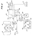
- ein Schema eines Steuerungssystems mit Durchsatzkontrolle für die Erntemaschine aus Figur 1,
- Fig. 3
- eine seitliche perspektivische Ansicht eines Abschnitts des Schrägförderers der Erntemaschine aus Figur 1, in der ein einstellbarer Walzenanschlag mit einem Schalter gezeigt ist, der die Arbeitsaufnahme einer automatischen Steuerung ermöglicht,
- Fig. 4
- eine vergrößerte Ansicht eines Abschnitts des Schrägförderers aus Figur 3, in der der am Anschlag angebrachte Schalter gezeigt wird,
- Fig. 5
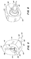
- eine perspektivische walzenseitige Ansicht des Anschlags und des Schalters aus Figur 3, und
- Fig. 6
- eine perspektivische Ansicht des Anschlags und des Schalters aus Figur 5, gesehen von der gegenüberliegenden oder nach außen gewandten Seite des Schalters.
- Fig. 1
- a side view of a harvester,
- Fig. 2
- 2 shows a diagram of a control system with throughput control for the harvesting machine from FIG. 1,
- Fig. 3
- 2 shows a side perspective view of a section of the inclined conveyor of the harvesting machine from FIG. 1, in which an adjustable roller stop is shown with a switch which enables automatic control to be started,
- Fig. 4
- 3 shows an enlarged view of a section of the inclined conveyor from FIG. 3, in which the switch attached to the stop is shown,
- Fig. 5
- a perspective roller-side view of the stop and the switch of Figure 3, and
- Fig. 6
- a perspective view of the stop and the switch of Figure 5, seen from the opposite or facing side of the switch.
Es wird auf die Figur 1 Bezug genommen, in der eine
landwirtschaftliche Erntemaschine in Form eines Mähdreschers 10
gezeigt ist, der eine tragende Struktur oder einen Rahmen 12 mit
im Eingriff mit dem Erdboden stehenden Rädern 14 umfasst, die
von der tragenden Struktur abstehen. Obwohl der Mähdrescher 10
mit Rädern dargestellt ist, könnte er auch mit zwei oder vier im
Bodeneingriff befindlichen Gleisketten versehen sein. Ein
Schneidwerk 16 wird zum Ernten von Erntegut und um es einem
Schrägförderer 18 zuzuführen benutzt. Der Schrägförderer 18
enthält eine Fördereinrichtung 19, die um eine vordere Walze 19d
herumgeführt ist, um das geerntete Gut einer Leittrommel 20
zuzuführen. Die Leittrommel 20 führt das Gut nach oben durch
einen Einlassübergangsabschnitt 22 hindurch und einem drehbaren
Dresch- und Trennzusammenbau 24 zu. Obwohl der dargestellte
Dresch- und Trennzusammenbau 24 axial im Mähdrescher 10
angeordnet ist, könnte er in anderen Orientierungen relativ zur
Längsachse des Mähdreschers 10 angeordnet sein. Obwohl die
vorliegende Erfindung anhand eines Dresch- und Trennzusammenbaus
24 mit einem Rotor beschrieben wird, könnte sie auch an einem
Feldhäcksler, einer Ballenpresse oder einem Mähdrescher 10 mit
einer konventionellen, quer angeordneten Dreschtrommel, die mit
einem Dreschkorb zusammenwirkt, verwendet werden.Reference is made to FIG. 1, in which a
agricultural harvester in the form of a
Der drehbare Dresch- und Trennzusammenbau 24 drischt und trennt
das geerntete Gut. Das Korn und die Spreu fallen durch Roste am
Boden des Zusammenbaus 24 in ein Reinigungssystem 26. Das
Reinigungssystem 26 entfernt die Spreu und führt das saubere
Korn einem (nicht gezeigten) Elevator für sauberes Korn zu. Der
Elevator für sauberes Korn legt das Korn in einem Korntank 28
ab. Das saubere Korn im Korntank 28 kann durch einen
Entladeschneckenförderer 30 auf einen Lastwagen oder Anhänger
entladen werden.The rotatable threshing and separating
Ausgedroschenes, vom Korn befreites Stroh wird von dem Dreschund
Trennzusammenbau 24 durch einen Auslass 32 einer
Auswurftrommel 34 zugeführt. Die Auswurftrommel 34 stößt das
Stroh wiederum an der Rückseite des Mähdreschers 10 aus. Es ist
anzumerken, dass die Auswurftrommel 34 das vom Korn befreite Gut
auch direkt einem Strohhäcksler zuführen könnte. Der Betrieb des
Mähdreschers 10 wird von einer Bedienerkabine 35 aus gesteuert. Threshed straw, freed from grain, becomes the threshing
Der drehbare Dresch- und Trennzusammenbau 24 umfasst ein
zylindrisches Rotorgehäuse 36 und einen im Rotorgehäuse 36
angeordneten, drehbaren Rotor 37. Der vordere Teil des Rotors 37
und das Rotorgehäuse 36 definieren einen Beschickungsabschnitt
38. Stromab des Beschickungsabschnitts 38 sind ein
Dreschabschnitt 39, ein Trennabschnitt 40 und ein
Auslassabschnitt 41. Der Rotor 37 ist im Beschickungsabschnitt
38 mit einer konischen Rotortrommel versehen, die wendelförmige
Beschickungselemente zum Eingreifen in Gut aufweist, das sie von
der Leittrommel 20 und vom Einlassübergangsbereich 22 erhält.
Unmittelbar stromab des Beschickungsabschnitts 38 befindet sich
der Dreschabschnitt 39. Im Dreschabschnitt 39 weist der Rotor 37
eine zylindrische Rotortrommel auf, die mit einer Anzahl von
Dreschelementen versehen ist, um das vom Beschickungsabschnitt
38 erhaltene Gut zu dreschen. Stromab des Dreschabschnitts 39
befindet sich der Trennabschnitt 40, in dem das im gedroschenen
Gut gefangene Korn freigesetzt wird und durch einen
bodenseitigen Rost im Rotorgehäuse 36 hindurch in das
Reinigungssystem 28 fällt. Der Trennabschnitt 40 geht in den
Auslassabschnitt 41 über, in dem das vom Korn verschiedene Gut
von der Gutbearbeitungseinrichtung 24 ausgestoßen wird.The rotatable threshing and separating
Die vorderen Räder 14 des Mähdreschers 10 werden durch einen
hydrostatischen Motor 49 angetrieben, der mit einem
hydrostatischen Getriebe 50 (Figur 2) verbunden ist. Der Motor
49 wird auf konventionelle Weise durch eine motorgetriebene
hydrostatische Pumpe 51 angetrieben. Die Pumpe 51 ist mit
einstellbaren Taumelplatten ausgestattet, die die
Ausgangsgeschwindigkeit und Drehrichtung des Getriebes 50
steuern. Elektromagnetische Steuerventile steuern die Positionen
der Taumelplatten. Das hydrostatische Getriebe 50 treibt ein
Schaltgetriebe 52 an, und zwei treibende Wellen 54 erstrecken
sich vom Schaltgetriebe 52 nach außen und treiben Endantriebe 56
der vorderen Räder 14 an. Die lenkbaren hinteren Räder 14 können
ebenfalls durch Radmotore angetrieben werden, die direkt an den
Rädern befestigt sind. Die Geschwindigkeit der Radmotore kann
durch das unten beschriebene Durchsatzsteuerungssystem gesteuert
werden.The
Ein verstellbarer Antrieb 60 mit variablem Drehmoment und Fühler
treibt den Rotor 37 an. Derselbe Verbrennungsmotor, der auch das
hydrostatische Getriebe 50 antreibt, treibt auch den
verstellbaren Antrieb 60 an. Der verstellbare Antrieb 60 umfasst
eine antreibende Riemenscheibe 62 mit variablem Durchmesser und
eine angetriebene Riemenscheibe 63 mit variablem Durchmesser.
Ein Riemen 64 erstreckt sich zwischen der antreibenden
Riemenscheibe 62 und der angetriebenen Riemenscheibe 63, um
Rotationsleistung auf den Rotor 37 zu übertragen. Ein
Hydraulikzylinder 66 steuert den Durchmesser der antreibenden
Riemenscheibe 62, und die angetriebene Riemenscheibe ist
federvorgespannt, um die Spannung des Riemens 64
aufrechtzuerhalten. Der Hydraulikzylinder 66 ist mit der
antreibenden Riemenscheibe 62 gekoppelt und bewegt die
Stirnplatten 68 der Riemenscheibe 62 nach innen bzw. außen, um
den wirksamen Durchmesser der Riemenscheibe 62 gegenüber dem
Riemen 64 zu steuern. Durch eine Änderung des wirksamen
Durchmessers der Riemenscheibe 62 wird die effektive
Geschwindigkeit der angetriebenen Riemenscheibe 63 geändert.
Durch eine Hydraulikleitung 70 wird dem Hydraulikzylinder 66
unter Druck stehende Hydraulikflüssigkeit von einem Ventilzusammenbau
72 zugeführt. Der Rotor 37 wird durch die Riemenscheiben
62, 63 variablen Durchmessers mit einer konstanten, ausgewählten
Rotorgeschwindigkeit angetrieben. Das vom Riemen 64 und den
Riemenscheiben 62, 63 übertragene Drehmoment variiert mit dem
Gutdurchsatz.An adjustable drive 60 with variable torque and sensor
drives the
Eine elektronische Steuerung 80 steuert die Erntegeschwindigkeit
des Mähdreschers 10, indem sie die elektromagnetisch betätigten
Steuerventile der hydrostatischen Pumpe 51 über die Leitung 82
steuert, um die Position der Taumelplatten in der Pumpe 51
einzustellen. Die Steuerung 80 empfängt durch die Leitung 84 ein
aktuelles Hydraulikdrucksignal oder den Druck des Aktors des
variablen Rotorantriebs von einem Hydraulikdrucksensor 86. Der
Druck des Aktors des variablen Rotorantriebs ist eine Funktion
der Zuführrate, und die Zuführrate tendiert dahin, bei
konstantem Druck des Aktors des variablen Rotorantriebs im
Wesentlichen konstant zu sein. Indem somit die
Erntegeschwindigkeit derart gesteuert wird, dass ein
vorbestimmter Druck des Aktors des variablen Rotorantriebs
aufrechterhalten wird, bleibt der Durchsatz im Wesentlichen
konstant. Der Hydraulikdrucksensor 86 erfasst den Hydraulikdruck
des Hydraulikzylinders 66, der den variablen Antrieb 60 mit
Fühler verstellt. Der Hydraulikdruck im variablen Antrieb 60 mit
Sensor steht mit dem Durchsatz in Beziehung, der wiederum
Erntequalitätsvariablen, wie Kornverlust, Kornbeschädigung und
Fremdanteil im Korn beeinflusst.An
Die Steuerung 80 empfängt über eine Leitung 88 von einer Bedienersteuerung
90 in der Kabine 35 oder ein anderes Eingabegerät
eine Signaleingabe über ein gewünschtes Erntequalitätsniveau,
wie eine annehmbare Kornverlustrate. Ein Erntequalitätsumsetzer
91, der in Figur 1 als nahe dem Auslass 32 angeordneter
Kornverlustsensor gezeigt ist, stellt der Steuerung 80
Erntequalitätssignale bereit. Ein Erntemaschinenneigungssensor
oder Umsetzer 92 ist an einer geeigneten Stelle des Rahmens 12
(Figur 1) abgestützt und stellt der Steuerung 80 Signale bereit,
die auf den Betrag hinweisen, um den sich die Erntemaschine aus
einer im Wesentlichen ebenen oder horizontalen Position, die in
Figur 1 gezeigt ist, hinausneigt. Der Umsetzer 92 stellt
vorzugsweise der Steuerung 80 Information über den seitlichen
Neigungswinkel und den Neigungswinkel in Fahrtrichtung bereit.
Wie in Figur 2 gezeigt ist, ist der Umsetzer direkt in die
Platine der Steuerung 80 integriert, um den Aufwand für einen
externen Sensor, ein separates Gehäuse und eine Verkabelung zu
vermeiden.
Um ein Startsignal für die automatische Steuerung
bereitzustellen, ist eine Erfassungseinrichtung 100 zur
Signalisierung des Vorhandenseins von Erntegut zwischen dem
Schneidwerk 16 und dem Eingang des Dresch- und Trennzusammenbaus
24 angeordnet. Die Erfassungseinrichtung 100 reagiert auf
Erntegut im Schrägförderer 18 und stellt der Steuerung 80 ein
Startsignal bereit. Die Steuerung 80 reagiert auf das
Startsignal, um mit der automatischen Steuerung anzufangen. Wie
gezeigt, umfasst die Erfassungseinrichtung 100 Näherungsschalter,
die auf die Bewegung der Walze 19d reagieren, die
daher resultiert, dass Erntegut in den Schrägförderer 18
eintritt. Wenn sich die Walze 19d mit dem Ernteguteintritt nach
oben bewegt, ändert der Schalter der Erfassungseinrichtung 100
seinen Zustand. Die Steuerung 80 erkennt die Änderung der
Zustände als einen Hinweis darauf, dass zu verarbeitendes
Erntegut bald in den Zusammenbau 24 eintreten wird.To a start signal for automatic control
is to be provided, a
Wie zeichnerisch dargestellt, ist die Erfassungseinrichtung 100
zur Signalisierung des Vorhandenseins von Erntegut an einem
Abschnitt einer Walzenjustierungsstruktur angebracht, die
insgesamt mit 110 gekennzeichnet ist. Die Walze 19d ist an ihren
Enden von den Seiten des Schrägförderers 18 durch
Verbindungsarme 112 mit verstellbarer Länge abgestützt, die
Spannanker zur Einstellung der Spannung der Förderkette 10c des
Schrägförderers 18 aufweisen. Die Förderkette 19c ist um die
Walze 19d herumgeführt und bewegt Erntegut entlang des Bodens
des Schrägförderers 18 nach hinten und oben zur Leittrommel 20.
Die Verbindungsarme 112 erlauben der Walze 19d, sich beim
Eintritt von Erntegut vertikal zu bewegen. Der ideale
anfängliche Zwischenraum zwischen der Walze 19d und dem Boden
des Schrägförderers 18 variiert bei verschiedenen Gutarten. Der
optimale Zwischenraum wird beispielsweise bei kleinen Körnern
kleiner sein als für Kolbenmais, und die Walzenjustierungsstruktur
110 stellt verschiedene untere Anschlaggrenzen bereit.As shown in the drawing, the
Die Walzenjustierungsstruktur 110 umfasst einen Nocken 114, der
drehbar von einer Konsole 116 abgestützt wird, die an der
Seitenwand des Schrägförderers 18 angeschraubt ist. Der Nocken
114 umfasst eine radial am weitesten außen angeordnete
Überhöhung 116 und eine zweite Überhöhung 118, die gegenüber der
Überhöhung 116 radial nach innen und um 90° versetzt ist. Die
Überhöhung 116 erstreckt sich nach oben, um die Unterseite des
Verbindungsarms 112 zu berühren, wenn die Struktur 110 auf
Kolbenmais eingestellt ist. Die Überhöhung 118 erstreckt sich
nach oben, um eine untere Anschlagsgrenze bereitzustellen, wenn
die Struktur 110 auf anderes Erntegut als Kolbenmais eingestellt
ist. Der Nocken 114 umfasst einen sich axial erstreckenden
Lagerabschnitt 120, der innerhalb einer Öffnung der Konsole 116
drehbar aufgenommen ist. Ein nicht-kreisförmiger Abschnitt 122
erstreckt sich vom Lagerabschnitt 120 axial nach außen und nimmt
einen Verstellhandgriff 124 auf, der eine passende Öffnung
besitzt. Ein hohler, mit Gewinde versehener Abschnitt 126
erstreckt sich vom Abschnitt 122 axial nach außen, und ein
Zusammenbau 128 mit Mutter und Unterlegscheibe ist auf den
Abschnitt 126 gegen den Handgriff 124 geschraubt, um die
Struktur 110 auf der Halterung 116 zu haltern. Die
Winkelposition des Handgriffs 124 entspricht der Winkelposition
der radial am weitesten außen angeordneten Überhöhung 116. Um
den unteren Grenzanschlag der Walze 19d einzustellen, wird der
Handgriff 124 zwischen der in den Figuren 3 und 4 gezeigten
obersten Position, in der die Überhöhung 116 den Verbindungsarm
112 berührt und einer untersten Position (neunzig Grad im
Uhrzeigersinn aus der in den Figuren 3 und 4 gezeigten Position)
gedreht, in der die Überhöhung 118 den Verbindungsarm 112
berührt. Um den Handgriff 124 in der ausgewählten unteren
Anschlagsposition zu sichern, wird ein Schnellanbringungsstift
132 in einer Öffnung im Handgriff 124 und in einem
entsprechenden Schlitz in der Konsole 116 positioniert.The
Der Nocken 114, der vorzugsweise aus Edelstahl hergestellt ist,
umfasst zwei Bohrungen 136 und 138, die sich von einer zentralen
Höhlung 140 im Wesentlichen radial auf die jeweiligen
Überhöhungen 116 und 118 zu erstrecken. Magnetisch gesteuerte
Reed-Schalter 141 und 142 sind innerhalb der Bohrungen 136 und
138 abgestützt und umfassen elektrische, in sie hineinführende
Drähte 144, die sich axial durch den hohlen Abschnitt des Nocken
114 erstrecken und mit einem Eingang der Steuerung 80 verbunden
sind. Ein langgestreckter Magnet 146 ist an der unteren, inneren
Kante des Verbindungsarms 112 abgestützt, um den Reed-Schalter
141 oder 142 zu betätigten, wenn der Verbindungsarm 112 sich in
der Anschlagsposition befindet und auf den Überhöhungen 116 bzw.
118 ruht. Der Magnet 146 erstreckt sich über eine hinreichende
Länge des Verbindungsarms 112, um den Betrieb der Reed-Schalter
141, 142 über den gesamten Verstellbereich des Verbindungsarms
112 sicherzustellen.The
Eine in der Bedienerkabine 35 angeordnete Bedienerkonsole 150
umfasst konventionelle Bedienereingabeeinrichtungen einschließlich
eines Hydroverschiebehebels 152 zur manuellen Steuerung des
Geschwindigkeitsbereichs und der Ausgangsgeschwindigkeit des
hydrostatischen Getriebes 50. Ein Bedienerschnittstellengerät
154 in der Bedienerkabine 35 erleichtert Eingaben von Informationen
in ein Prozessorsystem 80p, um eine automatische
Geschwindigkeitssteuerung und vielfältige andere Steuerfunktionen
für den Mähdrescher 10 bereitzustellen. Ausgaben von
verschiedenen an Bord befindlichen Sensoren 157 und Mikrocontrollern
158 werden von dem Bedienerschnittstellengerät 154
bereitgestellt. Der Bediener kann verschiedene Typen von
Informationen über die Eingabeleitungen 88 und 154a eingeben,
einschließlich der Gutart, des Orts, der Ausbeute, des
akzeptablen Kornverlusts, Beschädigungen, Fremdanteil und
dergleichen.An operator console 150 arranged in the
Für den Betrieb des Mähdreschers 10 wird der Steuerung 80 eine
gewünschte Erntequalitätsvariable, wie Verlustrate, unter
Verwendung der Bedienereingabeeinrichtung 90 zugeführt.
Basierend auf anfänglichen Voreinstellungseinträgen oder auf
gelernten Zusammenhängen berechnet die Steuerung 80 einen
anfänglichen Zieldruck des Aktors des variablen Rotorantriebs
entsprechend der Einstellung der Bedienereingabeeinrichtung 90.
Wenn eine automatische Steuerung gewünscht wird, wählt der
Bediener die automatische Steuerfunktion durch einen Schalter in
der Bedienerkonsole 150 aus. Wenn das Schneidwerk 16 oder ein
anderes Erntebergungsgerät am Mähdrescher 10 Erntegut aufnimmt
und es in den Schrägförderer 18 bewegt, hebt die Walze 19d von
dem Nocken 114 ab und ändert den Zustand der Reed-Schalter 141
bzw. 142 und stellt der Steuerung 80 ein Anfangssignal zum
Starten des automatischen Betriebs bereit.For the operation of the
Die Steuerung 80 empfängt das aktuelle Drucksignal vom
Hydraulikdruckumsetzer 86 und ein aktuelles Verlustratensignal
oder ein anderes Erntequalitätssignal vom Erntequalitätsumsetzer
91 und reguliert die Vorwärtsgeschwindigkeit des Mähdreschers
10, so dass sich der Druck des Aktors des variablen
Rotorantriebs auf das anfängliche Zielniveau einstellt. Die
Steuerung 80 fragt den Erntequalitätsumsetzer 91 ab und stellt
fest, ob sich die Verlustrate für den anfänglichen Zielwert des
Druck des Aktors bei dem gewünschten Niveau befindet, während
der Mähdrescher bei ebenen Bedingungen arbeitet. Wenn die
Verlustrate über einen ausgedehnten Zeitraum größer ist, als sie
von der Steuerung 80 für den anfänglichen Zielwert des Drucks
des Aktors bestimmt wurde, wird der Zieldruck des Aktors in der
Weise nach und nach vermindert, dass die
Vortriebsgeschwindigkeit des Mähdreschers vermindert wird, bis
die gewünschte Verlustrate erreicht ist, und ein neuer Zielwert
des Drucks des Aktors wird festgelegt. Wenn die Verlustrate über
einen ausgedehnten Zeitraum kleiner ist als die eingegebene
Rate, wird der Zieldruck des Aktors dadurch nach und nach
vergrößert, dass die Vortriebsgeschwindigkeit des Mähdreschers
erhöht wird, bis die gewünschte Verlustrate erreicht ist. Die
Steuerung 80 aktualisiert den Zieldruck des Aktors für den
Betrieb in der Ebene während des Erntens kontinuierlich, um sich
ändernde Bedingungen zu kompensieren.
Wenn sich der Mähdrescher 10 aus der nivellierten Lage neigt und
die Steuerung 80 ein Neigungssignal vom Neigungssensor 92
erhält, wird die Steuerung 80 den Mähdrescher 10 verlangsamen,
um den Durchsatz zu vermindern und dadurch einen Anstieg der
Erntequalitätsvariablen zu vermeiden. Durch eine Überwachung des
Signals vom Gerät 100 kann das Verlangsamen des Mähdreschers 10
verschoben oder hinausgezögert werden, falls das Signal darauf
hinweist, dass nur wenig oder kein Erntegut im Schrägförderer 18
vorhanden ist.When the
Der Prozessor 80p speichert oder berechnet eine Information über
die erwarteten Qualitätsvariablen als Funktion der
Neigungswinkel und des Durchsatzes. Für einen gegebenen
Neigungswinkel kann daher der Zielwert des Drucks des Aktors
verändert werden, um die Mähdreschergeschwindigkeit zu ändern,
so dass die Qualitätsvariable im Wesentlichen konstant bleiben
wird. Bei einer Ausführungsform der Erfindung lernt der
Prozessor 80p den Zusammenhang zwischen der Neigung, der
Erntequalität und dem Durchsatz und aktualisiert fortdauernd die
gespeicherte Information, so dass Durchsatzeinstellungen schnell
und genau durchgeführt werden können, sogar bei sich ändernden
Erntegut- und Erntebedingungen.The
Der Durchsatz wird gemessen als Funktion des Drucks des Aktors
des variablen Rotorantriebs (Umsetzer 86) und bleibt fast
konstant bei konstantem Druck des Aktors des variablen
Rotorantriebs. Während des Betriebs des Mähdreschers wird der
Druck des Aktors des variablen Rotorantriebs fortdauernd
überwacht. Falls der Druck des Aktors des variablen
Rotorantriebs vom gewünschten Bereich abweicht, wird die
Geschwindigkeit des Mähdreschers 10 gesteigert oder vermindert,
je nachdem, ob der Druck des Aktors des variablen Rotorantriebs
unter oder über dem Zielniveau liegt. Außerdem wird der
Neigungsumsetzer 92 abgefragt, um festzustellen, ob sich der
Mähdrescher aus einer ebenen Lage herausneigt. Wenn eine Neigung
des Mähdreschers 10 nachgewiesen wird, bestimmt der Prozessor
80p eine Beziehung zwischen den Verlusten, dem Druck des Aktors
des variablen Rotorantriebs und der Neigung, um eine
Korrelationsgleichung zu bestimmen oder im Speicher eine Karte
der Beziehungen zwischen dem Verlust und dem Druck des Aktors
des variablen Rotorantriebs als Funktion der Neigung abzulegen.
Wenn eine Neigung der Maschine nachgewiesen wird und ein
gesteigerter Verlust (oder eine andere Beeinträchtigung der
Erntequalität) nachgewiesen wird, modifiziert der Prozessor 80p
den Zielwert des Drucks des Aktors des variablen Rotorantriebs. The throughput is measured as a function of the pressure of the actuator
of the variable rotor drive (converter 86) and almost remains
constant at constant pressure of the variable actuator
Rotor drive. While the combine is operating, the
Pressure of the actuator of the variable rotor drive continues
supervised. If the actuator pressure of the variable
Rotor drive deviates from the desired range, the
Dieser Prozess ermöglicht es der Steuerung 80, die
Geschwindigkeit anzupassen, bis der Prozessor 80p den richtigen
Zusammenhang zwischen Neigung, Verlusten und Druck des Aktors
des variablen Rotorantriebs identifiziert und einen konstanten
Verlust aufrechterhalten kann, indem er im selben Moment den
Zielwert entsprechend des gelernten Zusammenhangs ändert.This process enables the
Indem das Signal von der Erfassungseinrichtung 100 fortdauernd
überwacht wird, können unnötige Verlangsamungen des Mähdreschers
10 und verminderte Produktivitäten vermieden werden, die
anderenfalls auftreten würden, wenn der Prozessor 80p bestimmte
Bedingungen erkennt, wenn nur wenig oder kein Erntegut an der
Walze 19d des Schrägförderers 18 vorhanden ist. Der Beginn der
automatischen Steuerung kann durch Überwachung des Signals der
Reed-Schalter 141 und 142 optimiert werden, so dass
Erntegutverluste und Steuerungsinstabilitäten vermindert oder
vermieden werden.By continuing the signal from
Claims (9)
Applications Claiming Priority (2)
| Application Number | Priority Date | Filing Date | Title |
|---|---|---|---|
| US10/021,581 US6834484B2 (en) | 2001-12-18 | 2001-12-18 | Automatic control initiation for a harvester |
| US21581 | 2001-12-18 |
Publications (2)
| Publication Number | Publication Date |
|---|---|
| EP1321025A1 true EP1321025A1 (en) | 2003-06-25 |
| EP1321025B1 EP1321025B1 (en) | 2007-02-14 |
Family
ID=21805032
Family Applications (1)
| Application Number | Title | Priority Date | Filing Date |
|---|---|---|---|
| EP02102728A Expired - Lifetime EP1321025B1 (en) | 2001-12-18 | 2002-12-11 | Harvester machine with crop detection device |
Country Status (8)
| Country | Link |
|---|---|
| US (1) | US6834484B2 (en) |
| EP (1) | EP1321025B1 (en) |
| AR (1) | AR037872A1 (en) |
| AU (1) | AU2002309050B2 (en) |
| BR (1) | BR0205253B1 (en) |
| CA (1) | CA2399234C (en) |
| DE (1) | DE50209468D1 (en) |
| DK (1) | DK1321025T3 (en) |
Cited By (4)
| Publication number | Priority date | Publication date | Assignee | Title |
|---|---|---|---|---|
| EP1668975A1 (en) | 2004-12-09 | 2006-06-14 | CLAAS Selbstfahrende Erntemaschinen GmbH | Agricultural working vehicle |
| EP2060165A1 (en) * | 2007-11-16 | 2009-05-20 | CLAAS Selbstfahrende Erntemaschinen GmbH | Self-propelled agricultural harvester |
| DE102007055074A1 (en) | 2007-11-16 | 2009-05-20 | Claas Selbstfahrende Erntemaschinen Gmbh | Self-propelled agricultural machine |
| EP3753391A1 (en) * | 2019-06-18 | 2020-12-23 | CLAAS Selbstfahrende Erntemaschinen GmbH | Material feed height roller in feed channel with rubber bearing mounting |
Families Citing this family (22)
| Publication number | Priority date | Publication date | Assignee | Title |
|---|---|---|---|---|
| DE10327758A1 (en) * | 2003-06-18 | 2005-01-05 | Claas Selbstfahrende Erntemaschinen Gmbh | Method for controlling a threshing unit of a combine harvester |
| DE102004036183A1 (en) * | 2004-07-26 | 2006-03-23 | Claas Selbstfahrende Erntemaschinen Gmbh | Inclined conveyor of an agricultural harvester |
| US8504256B2 (en) | 2012-01-06 | 2013-08-06 | Cnh America Llc | Harvester cruise control |
| DE102013106128A1 (en) * | 2012-07-16 | 2014-06-12 | Claas Selbstfahrende Erntemaschinen Gmbh | Agricultural work machine with at least one control device |
| CA2799093A1 (en) | 2012-12-18 | 2014-06-18 | Honey Bee Manufacturing Ltd. | Draper seal for crop header |
| DE102013100793A1 (en) * | 2013-01-28 | 2014-07-31 | Usines Claas France S.A.S. | Combination of a towing vehicle and an agricultural harvesting machine pulled therefrom |
| US8833048B2 (en) | 2013-02-14 | 2014-09-16 | Honey Bee Manufacturing, Ltd. | Harvesting header bat with adjustably spaced quick release fingers |
| BE1021155B1 (en) | 2013-07-03 | 2016-01-08 | Cnh Industrial Belgium Nv | HARVESTER FOR USE IN AGRICULTURE |
| US9265199B2 (en) * | 2013-11-21 | 2016-02-23 | Deere & Company | Side hill compensation for a harvesting head |
| US9901032B2 (en) | 2013-12-30 | 2018-02-27 | Honey Bee Manufacturing Ltd. | Harvesting header transport |
| US10021823B2 (en) | 2013-12-30 | 2018-07-17 | Honey Bee Manufacturing Inc. | Harvesting header transport apparatus and method |
| US9844183B2 (en) | 2014-03-26 | 2017-12-19 | Honey Bee Manufacturing Ltd. | Cam reel with complex bat path |
| CA2847456C (en) | 2014-03-26 | 2021-01-19 | Honey Bee Manufacturing Ltd. | Cam reel with complex bat path |
| DE102014105820A1 (en) * | 2014-04-25 | 2015-10-29 | Usines Claas France S.A.S. | Combination of a towing vehicle and a harvester pulled by it |
| CA2853947A1 (en) | 2014-06-09 | 2015-12-09 | Honey Bee Manufacturing Ltd. | Harvesting header knife drive assemby |
| CA2876686C (en) | 2014-12-24 | 2021-01-19 | Honey Bee Manufacturing Ltd. | Reel system |
| CA3062675C (en) | 2015-03-13 | 2021-03-23 | Honey Bee Manufacturing Ltd. | Controlling a positioning system for an agricultural implement |
| US10462966B2 (en) | 2015-03-13 | 2019-11-05 | Honey Bee Manufacturing Ltd. | Controlling a positioning system for an agricultural implement |
| JP6675843B2 (en) * | 2015-09-02 | 2020-04-08 | 株式会社クボタ | Combine |
| CA2937639A1 (en) | 2016-07-29 | 2018-01-29 | Honey Bee Manufacturing Ltd. | Header cutting system |
| US11140807B2 (en) | 2017-09-07 | 2021-10-12 | Deere & Company | System for optimizing agricultural machine settings |
| DE102018212075A1 (en) * | 2018-07-19 | 2020-01-23 | Deere & Company | Combine harvester with an inclined conveyor with an actuator-adjustable lower deflection roller |
Citations (10)
| Publication number | Priority date | Publication date | Assignee | Title |
|---|---|---|---|---|
| DE1407720A1 (en) * | 1961-09-08 | 1969-05-08 | Deere & Co | Procedure for achieving the optimal utilization of the combine harvester capacity |
| US3606742A (en) * | 1969-04-05 | 1971-09-21 | Franz Wieneke | Arrangement for the automatic control of the threshing process on combine harvesters |
| CA960873A (en) * | 1971-11-17 | 1975-01-14 | Leonard O. Short | Automatic feed rate control for combines |
| US4337611A (en) * | 1980-12-10 | 1982-07-06 | Purdue Research Foundation | Automatic control of a combine threshing cylinder and feeder conveyor |
| EP0077667A1 (en) * | 1981-10-21 | 1983-04-27 | Tecalemit Electronics Limited | Control apparatus for a combine harvester |
| US4487002A (en) * | 1981-07-17 | 1984-12-11 | Gary W. Krutz | Automatic ground speed controller |
| DE4311054A1 (en) * | 1993-04-03 | 1994-10-06 | Claas Ohg | Self-propelled agricultural harvesting machine |
| DE20001144U1 (en) * | 1999-02-04 | 2000-05-04 | Same Deutz Fahr Spa | Agricultural harvester |
| EP1243173A1 (en) * | 2001-03-20 | 2002-09-25 | Deere & Company | Elevator conveyor with force sensor for detecting the throughput of a combine |
| AU2613902A (en) * | 2001-03-20 | 2002-09-26 | Deere & Company | Throughput control for combines |
Family Cites Families (8)
| Publication number | Priority date | Publication date | Assignee | Title |
|---|---|---|---|---|
| US4327544A (en) * | 1981-05-06 | 1982-05-04 | Sperry Corporation | Variable speed indicator for combine |
| EP0122343B1 (en) * | 1983-04-15 | 1988-01-07 | Ford New Holland N.V. | Combine harvester |
| DE19524752B4 (en) * | 1995-07-07 | 2004-08-12 | Claas Kgaa Mbh | Device and method for measuring throughput in an agricultural harvesting machine |
| US6036597A (en) * | 1998-02-11 | 2000-03-14 | Agco Corporation | Combine harvester rotor load control |
| GB9811177D0 (en) * | 1998-05-26 | 1998-07-22 | Ford New Holland Nv | Methods for generating field maps |
| DE19903471C1 (en) * | 1999-01-29 | 2000-06-08 | Deere & Co | Crop machine throughput measurement arrangement derives throughput from distance between pre-baling rollers and crop speed, corrects for displacement force on pre-baling roller |
| DE19921466A1 (en) * | 1999-05-08 | 2000-11-09 | Deere & Co | Device for regulating the speed of advance of a harvesting machine with fuzzy logic |
| US6431981B1 (en) * | 1999-06-30 | 2002-08-13 | Wisconsin Alumni Research Foundation | Yield monitor for forage crops |
-
2001
- 2001-12-18 US US10/021,581 patent/US6834484B2/en not_active Expired - Fee Related
-
2002
- 2002-08-22 CA CA002399234A patent/CA2399234C/en not_active Expired - Fee Related
- 2002-11-29 AU AU2002309050A patent/AU2002309050B2/en not_active Ceased
- 2002-12-11 DK DK02102728T patent/DK1321025T3/en active
- 2002-12-11 DE DE50209468T patent/DE50209468D1/en not_active Expired - Lifetime
- 2002-12-11 EP EP02102728A patent/EP1321025B1/en not_active Expired - Lifetime
- 2002-12-13 BR BRPI0205253-9A patent/BR0205253B1/en not_active IP Right Cessation
- 2002-12-17 AR ARP020104903A patent/AR037872A1/en active IP Right Grant
Patent Citations (10)
| Publication number | Priority date | Publication date | Assignee | Title |
|---|---|---|---|---|
| DE1407720A1 (en) * | 1961-09-08 | 1969-05-08 | Deere & Co | Procedure for achieving the optimal utilization of the combine harvester capacity |
| US3606742A (en) * | 1969-04-05 | 1971-09-21 | Franz Wieneke | Arrangement for the automatic control of the threshing process on combine harvesters |
| CA960873A (en) * | 1971-11-17 | 1975-01-14 | Leonard O. Short | Automatic feed rate control for combines |
| US4337611A (en) * | 1980-12-10 | 1982-07-06 | Purdue Research Foundation | Automatic control of a combine threshing cylinder and feeder conveyor |
| US4487002A (en) * | 1981-07-17 | 1984-12-11 | Gary W. Krutz | Automatic ground speed controller |
| EP0077667A1 (en) * | 1981-10-21 | 1983-04-27 | Tecalemit Electronics Limited | Control apparatus for a combine harvester |
| DE4311054A1 (en) * | 1993-04-03 | 1994-10-06 | Claas Ohg | Self-propelled agricultural harvesting machine |
| DE20001144U1 (en) * | 1999-02-04 | 2000-05-04 | Same Deutz Fahr Spa | Agricultural harvester |
| EP1243173A1 (en) * | 2001-03-20 | 2002-09-25 | Deere & Company | Elevator conveyor with force sensor for detecting the throughput of a combine |
| AU2613902A (en) * | 2001-03-20 | 2002-09-26 | Deere & Company | Throughput control for combines |
Cited By (8)
| Publication number | Priority date | Publication date | Assignee | Title |
|---|---|---|---|---|
| EP1668975A1 (en) | 2004-12-09 | 2006-06-14 | CLAAS Selbstfahrende Erntemaschinen GmbH | Agricultural working vehicle |
| US9072223B2 (en) | 2004-12-09 | 2015-07-07 | Claas Selbstfahrende Erntemaschinen Gmbh | Agricultural working machine forward travel regulator |
| EP2060165A1 (en) * | 2007-11-16 | 2009-05-20 | CLAAS Selbstfahrende Erntemaschinen GmbH | Self-propelled agricultural harvester |
| DE102007055073A1 (en) | 2007-11-16 | 2009-05-20 | Claas Selbstfahrende Erntemaschinen Gmbh | Self-propelled agricultural harvester |
| DE102007055074A1 (en) | 2007-11-16 | 2009-05-20 | Claas Selbstfahrende Erntemaschinen Gmbh | Self-propelled agricultural machine |
| EP2060164A1 (en) | 2007-11-16 | 2009-05-20 | CLAAS Selbstfahrende Erntemaschinen GmbH | Self-propelled agricultural machine |
| US8161718B2 (en) | 2007-11-16 | 2012-04-24 | Claas Selbstfahrende Erntemaschinen Gmbh | Self-propelled agricultural working machine |
| EP3753391A1 (en) * | 2019-06-18 | 2020-12-23 | CLAAS Selbstfahrende Erntemaschinen GmbH | Material feed height roller in feed channel with rubber bearing mounting |
Also Published As
| Publication number | Publication date |
|---|---|
| DK1321025T3 (en) | 2007-06-11 |
| AR037872A1 (en) | 2004-12-09 |
| CA2399234C (en) | 2007-01-09 |
| BR0205253B1 (en) | 2009-05-05 |
| EP1321025B1 (en) | 2007-02-14 |
| CA2399234A1 (en) | 2003-06-18 |
| US20030110748A1 (en) | 2003-06-19 |
| DE50209468D1 (en) | 2007-03-29 |
| AU2002309050B2 (en) | 2008-07-31 |
| US6834484B2 (en) | 2004-12-28 |
| BR0205253A (en) | 2004-07-20 |
Similar Documents
| Publication | Publication Date | Title |
|---|---|---|
| EP1321025B1 (en) | Harvester machine with crop detection device | |
| EP1297734B1 (en) | Harvesting machine with an inclination-dependent rate of advance | |
| EP3403485B1 (en) | Self-learning assembly which incorporates correcting inputs for automatic controlling of a work parameter of a crop conveyor and/or processing device | |
| EP1281310B1 (en) | Harvesting machine with speed control | |
| EP1243173B1 (en) | Elevator conveyor with force sensor for detecting the throughput of a combine | |
| EP1668975B1 (en) | Self propelled working vehicle | |
| EP2223588B1 (en) | Automotive harvesting machine | |
| EP2681984B1 (en) | Combine harvester | |
| EP1306536B1 (en) | Vehicle engine control | |
| EP1051898B1 (en) | Device for regulate the rate of advance of a harvester by fuzzy logic | |
| EP2060164B1 (en) | Self-propelled agricultural machine | |
| EP1266558B1 (en) | Elevator conveyor with force sensor for detecting the throughput of a combine | |
| DE10134137B4 (en) | Self-propelled agricultural harvester | |
| EP2060165B1 (en) | Self-propelled agricultural harvester | |
| EP2308281B1 (en) | Harvester | |
| EP3326446B1 (en) | Speed control of a harvesting machine | |
| EP3597027B1 (en) | Combine with an inclined conveyor with lower deflection roller adjusted by means of an actuator | |
| EP2636297A1 (en) | Self-propelled harvester | |
| EP1243174A1 (en) | Combine with humidity sensor | |
| EP3348135B1 (en) | Drive system for a harvesting attachment of a harvesting machine with automatic shut-off in the case of overload | |
| BE1029599A1 (en) | Drive system for a harvesting machine | |
| DE102013214561B4 (en) | Forage harvester with an arrangement for controlling the height of a front pressure bar of a header |
Legal Events
| Date | Code | Title | Description |
|---|---|---|---|
| PUAI | Public reference made under article 153(3) epc to a published international application that has entered the european phase |
Free format text: ORIGINAL CODE: 0009012 |
|
| AK | Designated contracting states |
Designated state(s): AT BE BG CH CY CZ DE DK EE ES FI FR GB GR IE IT LI LU MC NL PT SE SI SK TR |
|
| AX | Request for extension of the european patent |
Extension state: AL LT LV MK RO |
|
| 17P | Request for examination filed |
Effective date: 20031229 |
|
| AKX | Designation fees paid |
Designated state(s): BE DE DK FR GB IT |
|
| GRAP | Despatch of communication of intention to grant a patent |
Free format text: ORIGINAL CODE: EPIDOSNIGR1 |
|
| GRAS | Grant fee paid |
Free format text: ORIGINAL CODE: EPIDOSNIGR3 |
|
| GRAA | (expected) grant |
Free format text: ORIGINAL CODE: 0009210 |
|
| AK | Designated contracting states |
Kind code of ref document: B1 Designated state(s): BE DE DK FR GB IT |
|
| REG | Reference to a national code |
Ref country code: GB Ref legal event code: FG4D Free format text: NOT ENGLISH |
|
| REF | Corresponds to: |
Ref document number: 50209468 Country of ref document: DE Date of ref document: 20070329 Kind code of ref document: P |
|
| GBT | Gb: translation of ep patent filed (gb section 77(6)(a)/1977) |
Effective date: 20070308 |
|
| ET | Fr: translation filed | ||
| PLBE | No opposition filed within time limit |
Free format text: ORIGINAL CODE: 0009261 |
|
| STAA | Information on the status of an ep patent application or granted ep patent |
Free format text: STATUS: NO OPPOSITION FILED WITHIN TIME LIMIT |
|
| 26N | No opposition filed |
Effective date: 20071115 |
|
| PGFP | Annual fee paid to national office [announced via postgrant information from national office to epo] |
Ref country code: GB Payment date: 20131227 Year of fee payment: 12 |
|
| PGFP | Annual fee paid to national office [announced via postgrant information from national office to epo] |
Ref country code: IT Payment date: 20131223 Year of fee payment: 12 Ref country code: FR Payment date: 20131217 Year of fee payment: 12 |
|
| GBPC | Gb: european patent ceased through non-payment of renewal fee |
Effective date: 20141211 |
|
| REG | Reference to a national code |
Ref country code: FR Ref legal event code: ST Effective date: 20150831 |
|
| PG25 | Lapsed in a contracting state [announced via postgrant information from national office to epo] |
Ref country code: GB Free format text: LAPSE BECAUSE OF NON-PAYMENT OF DUE FEES Effective date: 20141211 |
|
| PG25 | Lapsed in a contracting state [announced via postgrant information from national office to epo] |
Ref country code: FR Free format text: LAPSE BECAUSE OF NON-PAYMENT OF DUE FEES Effective date: 20141231 |
|
| PG25 | Lapsed in a contracting state [announced via postgrant information from national office to epo] |
Ref country code: IT Free format text: LAPSE BECAUSE OF NON-PAYMENT OF DUE FEES Effective date: 20141211 |
|
| PGFP | Annual fee paid to national office [announced via postgrant information from national office to epo] |
Ref country code: SE Payment date: 20181108 Year of fee payment: 9 |
|
| PGFP | Annual fee paid to national office [announced via postgrant information from national office to epo] |
Ref country code: BE Payment date: 20181227 Year of fee payment: 17 |
|
| REG | Reference to a national code |
Ref country code: DK Ref legal event code: EBP Effective date: 20191231 |
|
| REG | Reference to a national code |
Ref country code: BE Ref legal event code: MM Effective date: 20191231 |
|
| PG25 | Lapsed in a contracting state [announced via postgrant information from national office to epo] |
Ref country code: BE Free format text: LAPSE BECAUSE OF NON-PAYMENT OF DUE FEES Effective date: 20191231 |
|
| PG25 | Lapsed in a contracting state [announced via postgrant information from national office to epo] |
Ref country code: DK Free format text: LAPSE BECAUSE OF NON-PAYMENT OF DUE FEES Effective date: 20191231 |
|
| REG | Reference to a national code |
Ref country code: DE Ref legal event code: R084 Ref document number: 50209468 Country of ref document: DE |
|
| PGFP | Annual fee paid to national office [announced via postgrant information from national office to epo] |
Ref country code: DE Payment date: 20211119 Year of fee payment: 20 |
|
| REG | Reference to a national code |
Ref country code: DE Ref legal event code: R071 Ref document number: 50209468 Country of ref document: DE |