EP1320244A1 - Modular Door Intercom System - Google Patents
Modular Door Intercom System Download PDFInfo
- Publication number
- EP1320244A1 EP1320244A1 EP02027577A EP02027577A EP1320244A1 EP 1320244 A1 EP1320244 A1 EP 1320244A1 EP 02027577 A EP02027577 A EP 02027577A EP 02027577 A EP02027577 A EP 02027577A EP 1320244 A1 EP1320244 A1 EP 1320244A1
- Authority
- EP
- European Patent Office
- Prior art keywords
- insert
- communication system
- station
- bus
- module
- Prior art date
- Legal status (The legal status is an assumption and is not a legal conclusion. Google has not performed a legal analysis and makes no representation as to the accuracy of the status listed.)
- Granted
Links
Images


Classifications
-
- H—ELECTRICITY
- H04—ELECTRIC COMMUNICATION TECHNIQUE
- H04M—TELEPHONIC COMMUNICATION
- H04M1/00—Substation equipment, e.g. for use by subscribers
- H04M1/02—Constructional features of telephone sets
- H04M1/0291—Door telephones
-
- H—ELECTRICITY
- H04—ELECTRIC COMMUNICATION TECHNIQUE
- H04M—TELEPHONIC COMMUNICATION
- H04M1/00—Substation equipment, e.g. for use by subscribers
- H04M1/71—Substation extension arrangements
- H04M1/715—Substation extension arrangements using two or more extensions per line
-
- H—ELECTRICITY
- H04—ELECTRIC COMMUNICATION TECHNIQUE
- H04M—TELEPHONIC COMMUNICATION
- H04M11/00—Telephonic communication systems specially adapted for combination with other electrical systems
- H04M11/02—Telephonic communication systems specially adapted for combination with other electrical systems with bell or annunciator systems
- H04M11/025—Door telephones
-
- H—ELECTRICITY
- H04—ELECTRIC COMMUNICATION TECHNIQUE
- H04M—TELEPHONIC COMMUNICATION
- H04M9/00—Arrangements for interconnection not involving centralised switching
- H04M9/02—Arrangements for interconnection not involving centralised switching involving a common line for all parties
-
- H—ELECTRICITY
- H04—ELECTRIC COMMUNICATION TECHNIQUE
- H04N—PICTORIAL COMMUNICATION, e.g. TELEVISION
- H04N7/00—Television systems
- H04N7/18—Closed-circuit television [CCTV] systems, i.e. systems in which the video signal is not broadcast
- H04N7/183—Closed-circuit television [CCTV] systems, i.e. systems in which the video signal is not broadcast for receiving images from a single remote source
- H04N7/186—Video door telephones
-
- H—ELECTRICITY
- H01—ELECTRIC ELEMENTS
- H01H—ELECTRIC SWITCHES; RELAYS; SELECTORS; EMERGENCY PROTECTIVE DEVICES
- H01H2229/00—Manufacturing
- H01H2229/022—Modular assembly
-
- H—ELECTRICITY
- H01—ELECTRIC ELEMENTS
- H01H—ELECTRIC SWITCHES; RELAYS; SELECTORS; EMERGENCY PROTECTIVE DEVICES
- H01H2300/00—Orthogonal indexing scheme relating to electric switches, relays, selectors or emergency protective devices covered by H01H
- H01H2300/03—Application domotique, e.g. for house automation, bus connected switches, sensors, loads or intelligent wiring
-
- Y—GENERAL TAGGING OF NEW TECHNOLOGICAL DEVELOPMENTS; GENERAL TAGGING OF CROSS-SECTIONAL TECHNOLOGIES SPANNING OVER SEVERAL SECTIONS OF THE IPC; TECHNICAL SUBJECTS COVERED BY FORMER USPC CROSS-REFERENCE ART COLLECTIONS [XRACs] AND DIGESTS
- Y02—TECHNOLOGIES OR APPLICATIONS FOR MITIGATION OR ADAPTATION AGAINST CLIMATE CHANGE
- Y02B—CLIMATE CHANGE MITIGATION TECHNOLOGIES RELATED TO BUILDINGS, e.g. HOUSING, HOUSE APPLIANCES OR RELATED END-USER APPLICATIONS
- Y02B90/00—Enabling technologies or technologies with a potential or indirect contribution to GHG emissions mitigation
- Y02B90/20—Smart grids as enabling technology in buildings sector
-
- Y—GENERAL TAGGING OF NEW TECHNOLOGICAL DEVELOPMENTS; GENERAL TAGGING OF CROSS-SECTIONAL TECHNOLOGIES SPANNING OVER SEVERAL SECTIONS OF THE IPC; TECHNICAL SUBJECTS COVERED BY FORMER USPC CROSS-REFERENCE ART COLLECTIONS [XRACs] AND DIGESTS
- Y04—INFORMATION OR COMMUNICATION TECHNOLOGIES HAVING AN IMPACT ON OTHER TECHNOLOGY AREAS
- Y04S—SYSTEMS INTEGRATING TECHNOLOGIES RELATED TO POWER NETWORK OPERATION, COMMUNICATION OR INFORMATION TECHNOLOGIES FOR IMPROVING THE ELECTRICAL POWER GENERATION, TRANSMISSION, DISTRIBUTION, MANAGEMENT OR USAGE, i.e. SMART GRIDS
- Y04S20/00—Management or operation of end-user stationary applications or the last stages of power distribution; Controlling, monitoring or operating thereof
- Y04S20/14—Protecting elements, switches, relays or circuit breakers
Definitions
- the present invention relates to a home communication system with at least a door station and at least one home station, at least each Home station is connected or connectable via a two-wire line.
- Today's house communication systems (door intercoms) use for connection one of possibly several home stations with a door station usually only two more wires.
- the Supply voltage for the subscriber devices as well as voice and eventual Transfer switching data via this pair of wires.
- the power supply will generally ensured via a central power supply.
- Such facilities can Bus systems or so-called "1 + n systems”.
- the door station serves as an exchange. Every home station is thereby via a separate line with the door station and with a ground line connected.
- the "1" in “1 + n” stands for the common ground line, the "n” for the number of home stations and thus the single wires.
- the Supply voltage from the power supply unit is fed to the door station and from from there to the individual home stations.
- the existing door and apartment stations consist of different devices for indoor and outdoor use, each device also specifically for the respective predetermined use, for example as a door station or is designed as a home station.
- each device also specifically for the respective predetermined use, for example as a door station or is designed as a home station.
- AP mounting surface
- UP installation under plaster
- UP installation under plaster
- the present invention has for its object a To create home communication system of the type mentioned, with which the effort for Manufacturing, warehousing and assembly are reduced while maintaining a high level Installation variability is achieved.
- this is achieved in that at least a subset of the existing door and / or home stations is modular, each modular station consisting of at least one main module and at least one a functional module, the / each main module in the manner of an electrical installation device a common building installation system from one socket-like insert that can be inserted into a standard electrical installation box there, the functional module electrically and / or mechanically with the Main module is connectable.
- each expediently Function module can be plugged directly onto the respective main module.
- the functional module is held via mechanical connecting means and / or via electrical connectors connected.
- Each basically universal for everyone Any main module that can be used receives a specific one for the respective one Station-specific device function by connecting to a specific, correspondingly coded function module or a specific additional main module and / or by special switching / setting means (coding switch).
- the invention thus becomes a modular house communication system created because of a few, very largely universally usable Components (modules) a simple and inexpensive manufacture, one low storage or storage costs, simple assembly (installation) as well as a wide range of variations.
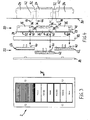
- Fig. 1 is an exemplary structure of a house communication system in one Execution as bus system illustrated.
- a system usually exists from (at least) one door station 2 installed in the outer area of a front door is, as well as from at least one home station 4, the indoor area is usually installed next to an apartment entrance door.
- four home stations 4 are provided.
- the facility is but can be expanded as required.
- the stations 2, 4 are common Bus connection 6 connected, which is preferably a 2-wire bus. Via the bus connection 6 all for communication and connection establishment transmit the required signals and commands.
- the bus connection 6 also serves for the power supply of the individual stations 2, 4.
- a central, to the Bus connection 6 connected bus control device 8 is provided, which in particular a power supply unit and preferably one from the home stations 4 Has door opener control 10 which can be controlled by digital signals.
- the Bus control unit 8 generates from a supply voltage V, usually the Mains voltage of 230 volts, an operating voltage for all stations 2, 4. This Operating voltage is supplied to all stations via bus connection 6.
- V usually the Mains voltage of 230 volts
- This Operating voltage is supplied to all stations via bus connection 6.
- a Call button actuation on the door station 2 uses a digital address code the bus connection 6 sent. This calls a specific home station 4, the was previously programmed for this address code during installation.
- the Home station 4 with a matching address code generates one after receipt Ringer.
- a voice connection to the door station 2 can thereby be established. Speech signals are preferably transmitted analogously via the bus connection 6.
- a door release button on home station 4 becomes a digital one Telegram transmitted as a command signal via the bus connection 6, which in Bus control device 8
- a light actuator 14 also preferably belongs to the system illustrated in FIG. 1 for controlling staircase lighting in larger residential buildings.
- the For this purpose, light actuator 14 receives a light button from home station 4 emitted, individual digital telegram as a command signal to activate the Stairway lighting.
- the light actuator 14 can also be in the stairwell installed light switch 16 can be activated.
- the lighting to be controlled is shown in FIG. 1 exemplified by only one lamp 18.
- actuators for example relays for certain switching functions, dimmers and / or the like may be provided.
- each door station 2 and each home station 4 are modular built up.
- Each station 2, 4 consists of at least one main module 20 and at least one function module 22.
- Each main module 20 is characterized by this from the fact that it is like a conventional electrical installation device from a socket-like, in a standard electrical installation box 24 (see Fig. 4 and 6) insert 26 is used.
- each insert 26 has a customary, frame- or plate-shaped support element 28 (e.g. so-called support ring).
- Each insert 26 is inserted into the can 24 that the support element 28 then essentially in the opening plane of the can 24 and lies on the edge of a mounting surface 30.
- Installation boxes 24 is a UP version, the Mounting surface 30 is a wall surface.
- Such UP cans are used in one Multiple arrangement plugged together via channel-like connections 32.
- This Connections 32 are used to make line connections.
- the Center distance of the cans 24 and thus also of the inserts 26 installed therein from each other corresponds to the usual installation pitch of in particular 71 mm.
- Each of these main modules 20 can be electrically and / or with a function module 22 mechanically connected.
- Each functional module 22 is expediently can be plugged directly onto the respective main module 20 and thus via mechanical connection means held and / or via electrical connectors connected.
- the existing modules 20, 22 are predominantly universal for the construction of the can be used throughout the system.
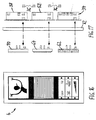
- FIG. 2 different main modules 20 are illustrated, all of which Stations, whether door station 2 or home station 4, can be set up.
- the first main module is a bus coupler insert 34, which is modular in each installed device must be available.
- This bus coupler insert 34 is that Link to the bus connection 6.
- the bus coupler 34 receives and sends Data from and to the bus connection 6.
- each station has 2, 4 generally have at least one further, second main module 20.
- each main module 20 has interfaces 38 (plug connectors), which are looped through internally.
- To connect the respective function module 22 are further connector parts 40 are provided, which at least partially the signals of Intembus 36 can transmit.
- 4 connecting lines 42 are provided, which are preferably as Flat cables consist of a few, for example six, wires.
- the Connection lines 42 can through the channel-like connections 32 of the Installation boxes 24 guided and via connector 44 with the internal bus interfaces 38 are connected.
- the connector 44 of the connecting lines 42 are designed in terms of their size in such a way that they can be passed through the Allow channel connections 32.
- the bus coupler insert 34 according to FIG. 2 has 6 corresponding connection elements for connecting the bus connection (especially double clamps). Other connection means are used for connection a storey call button 46 (doorbell button).
- a storey call button 46 doorbell button.
- connection elements provided for an additional supply line 48. hereby an additional power supply unit can be connected locally for the power supply. This additional supply can also lead directly to two Adem of the intembus 36 become.
- a key insert 50 can be used as an additional main module 20 Speech insert 52, a handset insert 54, a camera insert 56 and / or a Display insert 58 may be provided. It can also be the other main module 20 also according to FIGS. 12 and 13 around a speech recorder insert 60 or around one Act image recorder. Tasks and functions of these missions are as follows described in more detail.
- a function module 22 can be connected to the main modules 20 different types of function modules 22 become.
- a function module 22 are a key attachment 62 with preferably several (As shown, for example, three) push buttons, a speech attachment 64 with a microphone and / or loudspeaker, an earpiece receiving attachment 66 with holding means for an earpiece 68, a display attachment 70, a camera attachment and / or a signal attachment 72 with acoustic and / or optical signal generator provided.
- the bus coupler insert 34 receives and sends data to and from the bus connection 6. Received data are evaluated in an integrated microcontroller forwarded via the interface 38 to the internal bus 36 if necessary. To be sent The bus coupler 34 receives data from the intembus 36, which it evaluates and to which Bus connection 6 forwards. A preferably takes place in the bus coupler 34 Address comparison with the addresses previously stored during installation instead. Data, that are not intended for evaluation by the bus coupling unit are sent directly to the Intembus 36 forwarded. The bus coupler 34 is thus advantageous transparent.
- the bus coupler 34 is preferably used as a function module 22 with a Key attachment 62 connected, the keys in the case of a home station Form control buttons or call buttons in the case of a door station.
- the stations can be fitted with further key attachments 62 expand (especially for door station 2).
- the key insert 50 only grinds the Signals of the Interbus 36 on to the corresponding interfaces 38 and takes a key top 62.
- the speech insert 52 contains electronics for a hands-free function. This is usually used at door station 2. But also with the In principle, home stations 4 can have a hands-free function.
- a speech attachment 64 with loudspeaker and microphone is placed on the speech insert 52 placed.
- the interface 40 contains the necessary signal connections.
- Audio signals to be sent are sent from the speech insert 52 via the internal bus 36 the bus coupling unit 34 is sent, which amplifies the signals and opens them if necessary forwards the bus connection 6. Audio signals to be received from the Bus connection 6 are connected to the speech insert 52 through the bus coupler 34 forwarded.
- the speech electronics are activated controlled by the bus coupling unit 34, and only in the case of a voice connection after pressing a call button the door station 2.
- the handset insert 54 basically works analogously to the speech insert 52, but is the electronic effort is lower because of the connected handset 68 no feedback can occur and therefore it does not occur as with Speech insert 52 must be avoided by special measures.
- the listener 68 is connected to the handset insert 54 via a connecting cable.
- the camera insert 56 is used for video door intercoms.
- the Camera insert 56 has a lens 74 and preferably a light source 76 Illumination of the object to be displayed.
- a camera cover 78 is placed (cf. 14 and 15).
- a camera attachment can also be used instead of the cover 78 be provided, which then has the actual camera, the camera insert 56 essentially only contains the electronics required for signal transmission
- Video signal can be used as a standard video signal via a separate bus / video line 80 be transmitted.
- the video signal can also be in one Frequency range modulated outside the hearing frequency range and over the Internal bus 36 routed and sent via bus coupler 34 to bus connection 6 become.
- the display insert 58 (also for video door intercom systems) basically works Similar to the camera insert 56, only the video signals are received and via the display attachment 70 to be attached (or alternatively via an integrated Display).
- 3 is an example of the structure of the door station 2 illustrated. This is, for example, an audio version with six call buttons.
- This embodiment is implemented with three main modules 20, namely a mandatory bus coupler insert 34, a speech insert 52 and one Additional key insert 50.
- Two key attachments 62 are function modules 22 and a speech essay 64 is provided.
- the main modules 20 and the functional modules 22 is also a carrier frame 82 arranged, and a frame 84 is provided as an outer cover.
- Further Keys can be arranged with corresponding key inserts 50 with corresponding Key attachments 62 can be realized.
- At least that with the bus coupling unit 34 too connecting key attachment 62 is programmed with a corresponding identifier, Via which the bus coupling unit 34 learns that it should and should only work as a door station Call buttons are provided.
- the bus coupler 34 and the receiver insert are the main modules 20 54 provided.
- the bus coupling unit 34 is equipped with a Key attachment 62 with a special identifier (as a control button) connected, whereby the Bus coupling unit 34 works as a home station, that is, it causes reception of a matching address code, the output of a ring tone via the internal bus 36 to the handset 54, whereby a call sounds.
- the bus coupler 34 is activated to establish the connection via the handset 54 the speech-hearing circuit.
- the Information that the device has a handset is received by the bus coupling unit 34 via a specific identifier of the receiver insert 54.
- the Functions of the key top 62 are preferably staircase light activation here, Door release activation, call cut-off and volume control of the ring tone and Earpiece volume.
- this station is set up by a bus coupler 34 Key attachment 62 and through a speech insert 52 with speech attachment 64.
- Der Keypad 62 has an identifier (as a control button) for the home station and the Speech insert 52 is an identifier for hands-free calling.
- the bus coupling unit knows 34, which device is designed overall and can use the buttons as well as the respective Evaluate bus protocols accordingly, especially with regard to one Call acceptance button, which is not available on the handset. With this button the operator after receiving a call from another participant in the speech-hearing circuit activated.
- buttons 10 and 11 is the execution of a home station 4 with internal call buttons shown.
- These internal call keys can advantageously be used by one Home station other home stations can be called. So you can Communicate neighbors via the system according to the invention. You can use the buttons additional functions can be realized, for example switching lights, opening and Closing blinds, etc.
- the key tops 62 have different ones Identifiers on the one hand as control buttons and on the other hand as call buttons. That's why Avoiding undefined conditions provided that the identifier of the Control buttons have priority over the call buttons. Thus, for example, a Door station quickly by changing the keypad to the home station Hands-free function can be converted.
- a home station 4 with voice recorder insert 60 This is an additional device, which in the manner of a Answering machine in the absence of the resident voice messages Visitor records.
- the Voice recorder insert 60 connected to a key attachment 62, the keys have special control functions.
- the device is activated via a "Active" button.
- the resident can say an announcement text using a "Text” button Played after pressing the call button and via the loudspeaker at the door station 2 is reproduced.
- the recorder functions can be controlled using arrow keys.
- the Voice recorder insert 60 simulates call acceptance and even when activated establishes the connection to the calling station. If the voice recorder is listened to, so the device uses the speaker or handset. Basically, this could also a video recording using a video recorder or a Image recording can be provided by means of an image recorder.
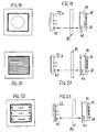
- the stations illustrated in Figures 14 to 17 are for video transmission designed. 14 and 15, the door station 2 contains a camera insert 56 with camera cover 78.
- the camera insert 56 is placed over the intembus 36 connected or placed anywhere.
- the camera 74 of the Camera insert 56 is controlled by bus coupling unit 34. Becomes one of the call buttons operated the door station 2, the camera is turned on, the video signal either sends via the separate video line 80 or modulated via the bus connection 6. When the connection is ended, the camera is switched off. A camera use can also be installed in the home station to create a video counter-connection realize.
- the camera insert 56 also reports to the identifier Bus coupling unit 34.
- the associated video home station 4 is illustrated in FIGS. 16 and 17. This is with the display insert 58 and the associated display attachment 70 fitted.
- the display insert 58 is also via the internal bus 36 connected or lined up.
- the display attachment 70 is from the bus coupling unit 34 controlled. When there is an incoming call, the display is switched on and shows this Image sent by the camera at the calling door station 2. After completing the Connection, the display is switched off.
- the display insert 58 also reports via a specific identifier at the bus coupling unit 34.
- FIG. 18 there are still certain modular additional devices illustrates that separately or in direct combination with a station 2, 4 can be installed.
- 18 and 19 is a light signal device, consisting of the bus coupler 34 and an optical signal attachment 72 (e.g. Strobe). This device enables hearing impaired people to use the optical Signaling a door call.
- an optical signal attachment 72 e.g. Strobe
- a call signal device consisting of Bus coupling unit 34 and acoustic signal attachment 72 (call attachment).
- This device serves as an additional device for amplifying the volume of a door call, especially in large ones Houses or apartments.
- FIGS. 22 and 23 show an additional button, which acts like an internal call button is working. It consists of the bus coupling unit 34 and a key top 62. Thereby however, an identifier is provided in such a way that the keys are used only for Sending switching commands to any actuator, such as light switches, Dimmers etc.
- the actuators are, for example, in an electrical sub-distribution and / or as built-in devices in false ceilings or the like. They include at Receive data the electronics corresponding to the bus coupling unit 34.
- House communication system in deviation from the previous concrete Description can also be a so-called "1 + n system”.
- This serves then the bus coupler 34 in each case as a connecting link between the intembus 36 and the external two-wire line, in which case the door station 2 correspondingly one has multi-core connection (one for each connected home station 4 separate wire + a common ground wire).
- the invention is not limited to that shown and described Embodiments limited, but also includes all within the meaning of the invention equivalent designs.
- the modular structure allows additional Main and / or function modules realized with almost any function be such.
- B. a code lock with numeric keypad, a transponder receiver (Radio receiver), personal identification devices (fingerprint / iris recognition), TK coupler for connection to a telecommunication system, any Actuators or the like.
- the invention is not yet based on the Claim 1 defined combination of features limited, but can also by any other combination of certain features all together disclosed individual features can be defined. This means that basically virtually every single feature of claim 1 omitted or by at least one individual feature disclosed elsewhere in the application is replaced can be. In this respect, claim 1 is only a first To understand formulation attempt for an invention.
Abstract
Description
Die vorliegende Erfindung betrifft eine Hauskommunikationsanlage mit mindestens einer Türstation und mindestens einer Wohnungsstation, wobei zumindest die/jede Wohnungsstation über eine Zweidraht-Leitung angeschlossen bzw. anschließbar ist.The present invention relates to a home communication system with at least a door station and at least one home station, at least each Home station is connected or connectable via a two-wire line.
Heutige Hauskommunikationsanlagen (Türsprechanlagen) verwenden zur Verbindung einer von eventuell mehreren Wohnungsstationen mit einer Türstation in der Regel nur noch zwei Leitungsadern. Dabei werden - wie bei einem analogen Telefon - die Versorgungsspannung für die Teilnehmergeräte sowie Sprach- und eventuelle Vermittlungsdaten über dieses Aderpaar übertragen. Die Spannungsversorgung wird im allgemeinen über einen zentrales Netzteil sichergestellt. Solche Anlagen können Bussysteme oder sogenannte "1+n-Anlagen" sein.Today's house communication systems (door intercoms) use for connection one of possibly several home stations with a door station usually only two more wires. As with an analog telephone, the Supply voltage for the subscriber devices as well as voice and eventual Transfer switching data via this pair of wires. The power supply will generally ensured via a central power supply. Such facilities can Bus systems or so-called "1 + n systems".
Bei 1+n-Anlagen dient die Türstation als Vermittlungsstelle. Jede Wohnungsstation ist dabei über eine eigene Leitung mit der Türstation sowie mit einer Masseleitung verbunden. Die "1" in "1+n" steht dabei für die gemeinsame Masseleitung, das "n" für die Anzahl der Wohnungsstationen und damit der Einzeladern. Die Versorgungsspannung aus dem Netzteil wird dabei an die Türstation geführt und von dort aus an die einzelnen Wohnungsstationen.With 1 + n systems, the door station serves as an exchange. Every home station is thereby via a separate line with the door station and with a ground line connected. The "1" in "1 + n" stands for the common ground line, the "n" for the number of home stations and thus the single wires. The Supply voltage from the power supply unit is fed to the door station and from from there to the individual home stations.
Bei Busanlagen werden alle Teilnehmer, ob Tür- oder Wohnungsstation, an eine gemeinsame Zweidraht-Busleitung angeschlossen, die an ein Netzteil geführt ist, welches die erforderliche Betriebsspannung über die Busleitung einspeist. Solche Hauskommunikationsanlagen bzw. sogenannte Türsprechanlagen des Typs "Zweidraht-Bussystem" sind beispielsweise in den Druckschriften DE 195 48 744 C2, DE 197 16 598 C1, DE 197 16 599 C2 und DE 30 23 988 A1 beschrieben.In bus systems, all participants, whether door or home station, are connected to one shared two-wire bus line connected to a power supply unit, which feeds the required operating voltage via the bus line. Such House communication systems or so-called door intercoms of the type "Two-wire bus system" are described, for example, in documents DE 195 48 744 C2, DE 197 16 598 C1, DE 197 16 599 C2 and DE 30 23 988 A1.
Bei bekannten Anlagen bestehen die vorhandenen Tür- und Wohnungsstationen aus unterschiedlichen Geräten für den Innen- und Aussenbereich, wobei jedes Gerät zudem speziell für die jeweils vorbestimmte Verwendung zum Beispiel als Türstation oder als Wohnungsstation konzipiert ist. Üblicherweise handelt es sich um jeweils einheitliche Geräte mit einem auf einer Montagefläche (zum Beispiel einer Wand), also "auf Putz (AP)" zu installierenden Gerätegehäuse. Eine Installation unter Putz (UP) ist nur auf sehr aufwändige Weise über recht große UP-Kästen möglich. Im Falle einer nachträglichen Gebäudeinstallation bedingt dies aufwändige Stemmarbeiten. Diese bekannten Anlagen führen deshalb zu einem hohen Aufwand für Herstellung der einzelnen Geräte, Lagerhaltung (Bereitstellung verschiedener Geräte) und auch Montage.In known systems, the existing door and apartment stations consist of different devices for indoor and outdoor use, each device also specifically for the respective predetermined use, for example as a door station or is designed as a home station. Usually they are each uniform devices with one on a mounting surface (for example a wall), so Device housing to be installed "on plaster (AP)". An installation under plaster (UP) is only possible in a very complex manner using quite large UP boxes. In case of a retrofitting the building requires extensive chiselling work. This Known systems therefore lead to a high expenditure for the production of individual devices, warehousing (provision of various devices) and also Assembly.
Der vorliegenden Erfindung liegt die Aufgabe zugrunde, eine Hauskommunikationsanlage der genannten Art zu schaffen, mit der der Aufwand für Herstellung, Lagerhaltung und Montage reduziert und dabei eine hohe Installationsvariabilität erreicht wird.The present invention has for its object a To create home communication system of the type mentioned, with which the effort for Manufacturing, warehousing and assembly are reduced while maintaining a high level Installation variability is achieved.
Erfindungsgemäß wird dies dadurch erreicht, dass zumindest eine Teilmenge der vorhandenen Tür- und/oder Wohnungsstationen modular aufgebaut ist, wobei jede modular aufgebaute Station aus mindestens einem Hauptmodul sowie mindestens einem Funktionsmodul besteht, wobei das/jedes Hauptmodul nach Art eines Elektro-Installationsgerätes eines üblichen Gebäudeinstallationssystems aus einem sockelartigen, in eine normgemäße Elektro-Installationsdose einsetzbaren Einsatz besteht, wobei das Funktionsmodul elektrisch und/oder mechanisch mit dem Hauptmodul verbindbar ist.According to the invention, this is achieved in that at least a subset of the existing door and / or home stations is modular, each modular station consisting of at least one main module and at least one a functional module, the / each main module in the manner of an electrical installation device a common building installation system from one socket-like insert that can be inserted into a standard electrical installation box there, the functional module electrically and / or mechanically with the Main module is connectable.
Durch diese vorteilhafte Ausgestaltung ist auf eine sehr einfache und damit wirtschaftliche Weise optional eine UP-Installation oder eine AP-Installation der einzelnen Stationen möglich, indem das jeweilige Hauptmodul lediglich - nach Art eines normgemäßen Installationsgerätes, wie Schalter, Steckdose oder dergleichen (in Deutschland DIN 49200 maßgeblich) - in eine übliche Installationsdose (UP oder AP) eingesetzt zu werden braucht. Für Unterputz-Gerätedosen ist in Deutschland insbesondere die DIN 49073 maßgeblich.This advantageous embodiment is very simple and therefore economically, an optional UP installation or an AP installation of the individual stations by simply adding the respective main module - according to Art a standard installation device, such as a switch, socket or the like (in Germany DIN 49200 relevant) - in a usual installation box (UP or AP) needs to be used. For flush-mounted device boxes is in Germany DIN 49073 is particularly relevant.
Mit besonderem Vorteil können alle oder zumindest eine überwiegende Anzahl der vorhandenen Tür- und Wohnungsstationen der Anlage aus universell einsetzbaren Haupt- und Funktionsmodulen aufgebaut sein, wobei zweckmäßig jedes Funktionsmodul unmittelbar auf das jeweilige Hauptmodul aufsteckbar ist. Dadurch wird das Funktionsmodul über mechanische Verbindungsmittel gehalten und/oder über elektrische Steckverbinder angeschlossen. Jedes grundsätzlich universell für jede beliebige Station einsetzbare Hauptmodul erhält eine bestimmte, für die jeweilige Station spezifische Gerätefunktion durch Verbindung mit einem bestimmten, entsprechend kodierten Funktionsmodul oder einem bestimmten weiteren Hauptmodul und/oder durch spezielle Schalt-/Einstellmittel (Kodierschalter).With particular advantage, all or at least a majority of the Existing door and apartment stations in the system can be used universally Main and functional modules are constructed, each expediently Function module can be plugged directly onto the respective main module. Thereby the functional module is held via mechanical connecting means and / or via electrical connectors connected. Each basically universal for everyone Any main module that can be used receives a specific one for the respective one Station-specific device function by connecting to a specific, correspondingly coded function module or a specific additional main module and / or by special switching / setting means (coding switch).
Durch die Erfindung wird somit eine modular aufgebaute Hauskommunikationsanlage geschaffen, die auf Grund von wenigen, sehr weitgehend universell verwendbaren Komponenten (Modulen) eine einfache und kostengünstige Herstellung, einen geringen Lager- bzw. Bevorratungsaufwand, eine einfache Montage (Installation) sowie ein großes Variationsspektrum gewährleistet.The invention thus becomes a modular house communication system created because of a few, very largely universally usable Components (modules) a simple and inexpensive manufacture, one low storage or storage costs, simple assembly (installation) as well as a wide range of variations.
Weitere vorteilhafte Ausgestaltungsmerkmale und Vorteile der Erfindung sind in den Unteransprüchen und der folgenden Beschreibung enthalten.Further advantageous design features and advantages of the invention are in the Subclaims and the following description included.
An Hand der Zeichnung soll die Erfindung beispielhaft genauer erläutert werden. Dabei zeigen:
- Fig. 1
- eine schematische, blockschaltbildartige Darstellung einer Hauskommunikationsanlage in bevorzugter Ausführung als Bussystem und in einem beispielhaften Ausbauumfang,
- Fig.2
- mehrere Ausführungsformen von Hauptmodulen nach der Erfindung jeweils in stark schematischer Seitenansicht,
- Fig. 3
- ein Beispiel einer Türstation in einer Ansicht auf die Vorderseite (Bedienungsseite),
- Fig. 4
- eine schematische Explosions-Seitenansicht der Bestandteile in Pfeilrichtung IV gemäß Fig. 3,
- Fig. 5
- eine Ansicht einer Wohnungsstation analog zu Fig. 3 in einer ersten möglichen Ausführung,
- Fig. 6
- eine Seitenansicht analog zu Fig. 4 in Pfeilrichtung VI gemäß Fig. 5,
- Fig. 7
- eine Ansicht einer Wohnungsstation in einer Ausführungsvariante,
- Fig. 8
- eine Explosions-Seitenansicht dieser Wohnungsstation nach Fig. 7,
- Fig. 9
- eine Ansicht in Pfeilrichtung IX der Komponenten nach Fig. 8,
- Fig. 10
- eine weitere Ausführungsvariante einer Wohnungsstation in Vorderansicht,
- Fig. 11
- die Wohnungsstation nach Fig. 10 in Explosions-Seitenansicht (Pfeilrichtung XI gemäß Fig. 10),
- Fig. 12 und 13
- eine weitere Ausführung einer Wohnungsstation in Ansichten analog zu beispielsweise Fig. 3 und 4,
- Fig. 14 und 15
- weitere Ansichten wie zuvor einer alternativen Ausführung einer Türstation,
- Fig. 16 und 17
- analoge Ansichten einer zugehörigen Wohnungsstation ,
- Fig. 18 und 19
- gleichartige Ansichten eines speziellen Lichtsignalgerätes,
- Fig. 20 und 21
- entsprechende Ansichten eines speziellen Rufsignalgerätes und
- Fig. 22 und 23
- gleichartige Darstellungen eines speziellen Tastergerätes.
- Fig. 1
- 1 shows a schematic, block diagram representation of a house communication system in a preferred embodiment as a bus system and in an exemplary scope of expansion,
- Fig.2
- several embodiments of main modules according to the invention each in a highly schematic side view,
- Fig. 3
- an example of a door station in a view from the front (operating side),
- Fig. 4
- 3 shows a schematic exploded side view of the components in the direction of arrow IV according to FIG. 3,
- Fig. 5
- 3 shows a view of a home station analogous to FIG. 3 in a first possible embodiment,
- Fig. 6
- 4 in the direction of arrow VI in FIG. 5,
- Fig. 7
- a view of a home station in one embodiment,
- Fig. 8
- 7 shows an exploded side view of this home station according to FIG. 7,
- Fig. 9
- 8 shows a view in the direction of arrow IX of the components according to FIG. 8,
- Fig. 10
- another embodiment of a home station in front view,
- Fig. 11
- 10 in an exploded side view (arrow direction XI according to FIG. 10),
- 12 and 13
- another embodiment of a home station in views analogous to, for example, FIGS. 3 and 4,
- 14 and 15
- further views as before of an alternative version of a door station,
- 16 and 17
- analog views of an associated home station,
- 18 and 19
- similar views of a special light signal device,
- 20 and 21
- corresponding views of a special call signal device and
- 22 and 23
- Similar representations of a special push button device.
In den verschiedenen Figuren der Zeichnungen sind gleiche Teile stets mit den gleichen Bezugszeichen versehen. Daher gilt jede evtl. nur einmal vorkommende Beschreibung eines Teils auch für alle anderen Zeichnungsfiguren, in denen dieses Teil mit der entsprechenden Bezugsziffer ebenfalls zu erkennen ist.In the different figures of the drawings, the same parts are always with the provided with the same reference numerals. Therefore, every one that occurs only once applies Description of a part also for all other drawing figures in which this Part with the corresponding reference number can also be seen.
In Fig. 1 ist ein beispielhafter Aufbau einer Hauskommunikationsanlage in einer
Ausführung als Bussystem veranschaulicht. Eine solche Anlage besteht üblicherweise
aus (mindestens) einer Türstation 2, die im Aussenbereich einer Haustür installiert
wird, sowie aus mindestens einer Wohnungsstation 4, die im Innenbereich
üblicherweise neben einer Wohnungseingangstür installiert wird. Bei dem in Fig. 1
veranschaulichten Beispiel sind vier Wohnungsstationen 4 vorgesehen. Die Anlage ist
jedoch beliebig ausbaufähig. Die Stationen 2, 4 sind über eine gemeinsame
Busverbindung 6 verbunden, wobei es sich bevorzugt um einen 2-Draht-Bus handelt.
Über die Busverbindung 6 werden alle für Kommunikation und Verbindungsaufbau
benötigten Signale und Befehle übertragen. Zudem dient die Busverbindung 6 auch
zur Spannungsversorgung der einzelnen Stationen 2, 4. Dazu ist ein zentrales, an die
Busverbindung 6 angeschlossenes Bussteuergerät 8 vorgesehen, welches
insbesondere ein Netzteil und vorzugsweise eine von den Wohnungsstationen 4 aus
durch digitale Signale ansteuerbare Türöffner-Ansteuerung 10 aufweist. Das
Bussteuergerät 8 erzeugt aus einer Versorgungsspannung V, üblicherweise der
Netzspannung von 230 Volt, eine Betriebsspannung für alle Stationen 2, 4. Diese
Betriebsspannung wird über die Busverbindung 6 an alle Stationen geführt. Bei einer
Ruftastenbetätigung an der Türstation 2 wird von dieser ein digitaler Adresscode über
die Busverbindung 6 versendet. Dieser ruft eine bestimmte Wohnungsstation 4, die
zuvor bei der Installation auf diesen Adresscode programmiert wurde. Die
Wohnungsstation 4 mit übereinstimmendem Adresscode erzeugt nach Empfang einen
Rufton. Dadurch kann eine Sprechverbindung zur Türstation 2 hergestellt werden.
Sprachsignale werden bevorzugt analog über die Busverbindung 6 übertragen. Bei
Betätigung einer Türöffnertaste an der Wohnungsstation 4 wird ein digitales
Telegramm als Befehlssignal über die Busverbindung 6 übertragen, wodurch im
Bussteuergerät 8 über die Türöffner-Ansteuerung 10 ein Türöffner 12 aktiviert wird.In Fig. 1 is an exemplary structure of a house communication system in one
Execution as bus system illustrated. Such a system usually exists
from (at least) one
Zu der in Fig. 1 veranschaulichten Anlage gehört weiterhin bevorzugt ein Lichtaktor 14
zur Ansteuerung einer Treppenhausbeleuchtung in größeren Wohnhäusern. Der
Lichtaktor 14 empfängt dazu ein von einer Lichttaste der Wohnungsstation 4
ausgesendetes, individuelles digitales Telegramm als Befehlssignal zur Aktivierung der
Treppenhausbeleuchtung. Zudem kann der Lichtaktor 14 auch über im Treppenhaus
installierte Lichttaster 16 aktiviert werden. Die zu steuemde Beleuchtung ist in Fig. 1
beispielhaft durch nur eine Leuchte 18 veranschaulicht.A light actuator 14 also preferably belongs to the system illustrated in FIG. 1
for controlling staircase lighting in larger residential buildings. The
For this purpose, light actuator 14 receives a light button from
Weiterhin können optional zusätzliche (beliebige) Aktoren, beispielsweise Relais für bestimmte Schaltfunktionen, Dimmer und/oder dergleichen vorgesehen sein.Furthermore, additional (arbitrary) actuators, for example relays for certain switching functions, dimmers and / or the like may be provided.
Erfindungsgemäß sind die (jede) Türstation 2 und jede Wohnungsstation 4 modular
aufgebaut. Jede Station 2, 4 besteht aus mindestens einem Hauptmodul 20 und
mindestens einem Funktionsmodul 22. Jedes Hauptmodul 20 zeichnet sich dadurch
aus, dass es nach Art eines üblichen Elektro-Installationsgerätes aus einem
sockelartigen, in eine normgemäße Elektro-Installationsdose 24 (siehe dazu Fig. 4 und
6) einsetzbaren Einsatz 26 besteht. Zur Befestigung in der jeweiligen Installationsdose
24 weist jeder Einsatz 26 ein übliches, rahmen- oder plattenförmiges Tragelement 28
(z. B. sogenannter Tragring) auf. Jeder Einsatz 26 wird so in die Dose 24 eingesetzt,
dass das Tragelement 28 dann im Wesentlichen in der Öffnungsebene der Dose 24
und randlich auf einer Montagefläche 30 liegt. Bei den in Fig. 4 und 6 dargestellten
Installationsdosen 24 handelt es sich um eine UP-Ausführung, wobei die
Montagefläche 30 eine Wandoberfläche ist. Derartige UP-Dosen werden bei einer
Mehrfachanordnung über kanalartige Verbindungen 32 zusammengesteckt. Diese
Verbindungen 32 dienen zum Durchführen von Leitungsverbindungen. Der
Mittenabstand der Dosen 24 und damit auch der darin installierten Einsätze 26
voneinander entspricht dem üblichen Installations-Stichmaß von insbesondere 71 mm.According to the (each)
Jedes dieser Hauptmodule 20 kann mit einem Funktionsmodul 22 elektrisch und/oder
mechanisch verbunden werden. Zweckmäßigerweise ist jedes Funktionsmodul 22
unmittelbar auf das jeweilige Hauptmodul 20 aufsteckbar und dadurch über
mechanische Verbindungsmittel gehalten und/oder über elektrische Steckverbinder
angeschlossen.Each of these
Die vorhandenen Module 20, 22 sind überwiegend universell zum Aufbau der
gesamten Anlage einsetzbar.The existing
In Fig. 2 sind unterschiedliche Hauptmodule 20 veranschaulicht, mit denen alle
Stationen, ob Türstation 2 oder Wohnungsstation 4, aufgebaut werden können. Als
erstes Hauptmodul ist ein Busankoppler-Einsatz 34 vorgesehen, der in jedem modular
aufgebauten Gerät vorhanden sein muss. Dieser Busankoppler-Einsatz 34 ist das
Verbindungsglied zur Busverbindung 6. Der Busankoppler 34 empfängt und sendet
Daten von und zur Busverbindung 6.In Fig. 2 different
Zusätzlich zu diesem ersten Hauptmodul 20, dem Busankoppler 34, weist jede Station
2, 4 in der Regel mindestens ein weiteres, zweites Hauptmodul 20 auf. Dabei sind die
Hauptmodule 20 innerhalb jeder einzelnen Station 2, 4 untereinander sowie eventuell
auch mit bestimmten zugehörigen Funktionsmodulen 22 über einen Internbus 36
verbindbar. Jedes Hauptmodul 20 weist dazu Schnittstellen 38 (Steckverbinder) auf,
die intern durchgeschleift sind. Zum Anschluss des jeweiligen Funktionsmoduls 22 sind
weitere Steckverbinderteile 40 vorgesehen, die zumindest teilweise die Signale des
Intembus 36 übertragen können. Zur gegenseitigen Verbindung der Hauptmodule 20
jeder Station 2, 4 sind Verbindungsleitungen 42 vorgesehen, die bevorzugt als
Flachleitungen aus wenigen, beispielsweise sechs Adern bestehen. Die
Verbindungsleitungen 42 können durch die kanalartigen Verbindungen 32 der
Installationsdosen 24 geführt und über Steckverbinder 44 mit den Internbus-Schnittstellen
38 verbunden werden. Die Steckverbinder 44 der Verbindungsleitungen
42 sind bzgl. ihrer Größe derart ausgelegt, dass sie ein Durchführen durch die
Kanalverbindungen 32 gestatten. Der Busankoppler-Einsatz 34 gemäß Fig. 2 weist
zum Anschluss der Busverbindung 6 entsprechende Anschlusselemente
(insbesondere Doppelklemmen) auf. Weitere Anschlussmittel dienen zum Anschluss
eines Etagenruftasters 46 (Türklingelknopf). Vorzugsweise sind zusätzliche
Anschlusselemente für eine Zusatz-Versorgungsleitung 48 vorgesehen. Hierdurch
kann lokal ein zusätzliches Netzteil zur Spannungsversorgung angeschlossen werden.
Diese Zusatzversorgung kann auch direkt auf zwei Adem des Intembusses 36 geführt
werden. In addition to this first
Gemäß Fig. 2 können als zusätzliches Hauptmodul 20 ein Tasteneinsatz 50, ein
Sprecheinsatz 52, ein Hörereinsatz 54, ein Kameraeinsatz 56 und/oder ein
Displayeinsatz 58 vorgesehen sein. Zudem kann es sich bei dem weiteren Hauptmodul
20 auch gemäß Fig. 12 und 13 um einen Sprachrekordereinsatz 60 oder um einen
Bildrekorder handeln. Aufgaben und Funktionen dieser Einsätze werden im Folgenden
noch genauer beschrieben.2, a
Wie sich an Hand der verschiedenen Ausführungsbeispiele ab Fig. 3 erkennen lässt,
können mit den Hauptmodulen 20 verschiedenartige Funktionsmodule 22 verbunden
werden. Als Funktionsmodul 22 sind ein Tastenaufsatz 62 mit vorzugsweise mehreren
(wie dargestellt beispielsweise drei) Drucktasten, ein Sprechaufsatz 64 mit Mikrophon
und/oder Lautsprecher, ein Hörer-Aufnahmeaufsatz 66 mit Haltemitteln für einen Hörer
68, ein Displayaufsatz 70, ein Kameraufsatz und/oder ein Signalaufsatz 72 mit
akustischem und/oder optischem Signalgeber vorgesehen.As can be seen from the various exemplary embodiments from FIG. 3,
can be connected to the
Der Busankoppler-Einsatz 34 empfängt und sendet Daten von und zur Busverbindung
6. Empfangene Daten werden in einem integrierten Microcontroller ausgewertet und
bei Bedarf über die Schnittstelle 38 zum Internbus 36 weitergeleitet. Zu sendende
Daten erhält der Busankoppler 34 vom Intembus 36, die er auswertet und auf die
Busverbindung 6 weiterleitet. Bevorzugt in dem Busankoppler 34 findet ein
Adressvergleich mit den zuvor bei der Installation abgelegten Adressen statt. Daten,
die nicht zur Auswertung durch den Busankoppler bestimmt sind, werden direkt an den
Intembus 36 weitergeleitet. Der Busankoppler 34 ist somit vorteilhafterweise
transparent. Als Funktionsmodul 22 wird der Busankoppler 34 bevorzugt mit einem
Tastenaufsatz 62 verbunden, dessen Tasten im Falle einer Wohnungsstation
Steuertasten bzw. im Falle einer Türstation Ruftasten bilden.The
Mit dem Tasteneinsatz 50 lassen sich die Stationen um weitere Tastenaufsätze 62
erweitem (insbesondere für die Türstation 2). Der Tasteneinsatz 50 schleift lediglich die
Signale des Interbusses 36 zu den entsprechenden Schnittstellen 38 weiter und nimmt
einen Tastenaufsatz 62 auf.With the
Der Sprecheinsatz 52 beinhaltet eine Elektronik für eine Freisprechfunktion. Diese
findet gewöhnlich an der Türstation 2 ihren Einsatz. Aber auch bei den
Wohnungsstationen 4 kann eine Freisprechfunktion grundsätzlich realisiert werden.
Auf den Sprecheinsatz 52 wird ein Sprechaufsatz 64 mit Lautsprecher und Mikrophon
aufgesetzt. Die Schnittstelle 40 beinhaltet die dafür notwendigen Signalverbindungen. The
Zu sendende Audiosignale werden vom Sprecheinsatz 52 über den Internbus 36 an
den Busankoppler 34 gesendet, welcher die Signale gegebenenfalls verstärkt und auf
die Busverbindung 6 weiterleitet. Zu empfangende Ausiosignale von der
Busverbindung 6 werden durch den Busankoppler 34 an den Sprecheinsatz 52
weitergeleitet. Die Sprechelektronik wird vom Busankoppler 34 gesteuert aktiviert, und
zwar nur im Falle eines Sprechverbindungsaufbaus nach einer Ruftastenbetätigung an
der Türstation 2.Audio signals to be sent are sent from the
Der Hörereinsatz 54 arbeitet grundsätzlich analog zum Sprecheinsatz 52, jedoch ist
der elektronische Aufwand geringer, weil auf Grund des angeschlossenen Hörers 68
keine Rückkopplungen auftreten können und diese deshalb auch nicht wie beim
Sprecheinsatz 52 durch spezielle Maßnahmen vermieden werden müssen. Der Hörer
68 wird über ein Anschlusskabel an dem Hörereinsatz 54 angeschlossen.The
Der Kameraeinsatz 56 wird für Video-Türsprechanlagen eingesetzt. Der
Kameraeinsatz 56 weist ein Objektiv 74 und bevorzugt eine Lichtquelle 76 zur
Beleuchtung des jeweils darzustellenden Objektes auf. Im Falle des Kameraeinsatzes
56 wird an Stelle eines Funktionsmoduls lediglich ein Kameradeckel 78 aufgesetzt (vgl.
Fig. 14 und 15). Alternativ kann dabei auch anstatt des Deckels 78 ein Kameraaufsatz
vorgesehen sein, der dann die eigentliche Kamera aufweist, wobei der Kameraeinsatz
56 im Wesentlichen nur die zur Signalübertragung erforderliche Elektronik enthält.Das
Videosignal kann als Normvideosignal über eine separate Bus-/Videoleitung 80
übertragen werden. Prinzipiell kann das Videosignal aber auch in einen
Frequenzbereich ausserhalb des Hörfrequenzbereichs moduliert und über den
Internbus 36 geleitet und über den Busankoppler 34 auf die Busverbindung 6 gesendet
werden.The
Der Displayeinsatz 58 (ebenfalls für Video-Türsprechanlagen) arbeitet grundsätzlich
ähnlich zum Kameraeinsatz 56, nur werden lediglich die Videosignale empfangen und
über den aufzusetzenden Displayaufsatz 70 (oder alternativ über ein integriertes
Display) angezeigt.The display insert 58 (also for video door intercom systems) basically works
Similar to the
Mit den genannten Modulen können nun nahezu beliebige Stationen 2, 4 auf einfache
Weise aufgebaut werden. Dies soll an Hand der konkreten Ausführungsbeispiele
erläutert werden. So ist zunächst in Fig. 3 ein Beispiel für den Aufbau der Türstation 2
veranschaulicht. Hier handelt es sich beispielsweise um eine Audio-Ausführung mit
sechs Ruftasten. Realisiert wird diese Ausführung mit drei Hauptmodulen 20, und zwar
einem obligatorischen Busankoppler-Einsatz 34, einem Sprecheinsatz 52 und einem
zusätzlichen Tasteneinsatz 50. Als Funktionsmodule 22 sind zwei Tastenaufsätze 62
und ein Sprechaufsatz 64 vorgesehen. Im Verbindungsbereich zwischen den
Hauptmodulen 20 und den Funktionsmodulen 22 ist zudem ein Trägerrahmen 82
angeordnet, und als äussere Abdeckung ist ein Blendrahmen 84 vorgesehen. Weitere
Tasten können durch Anreihung weiterer Tasteneinsätze 50 mit entsprechenden
Tastenaufsätzen 62 realisiert werden. Zumindest der mit dem Busankoppler 34 zu
verbindende Tastenaufsatz 62 ist mit einer entsprechenden Kennung programmiert,
über die der Busankoppler 34 erfährt, dass er als Türstation arbeiten soll und nur
Ruftasten vorgesehen sind.With the modules mentioned, almost any
In Fig. 5 und 6 ist eine Ausführung der Wohnungsstation 4 mit Hörer 68
veranschaulicht. Als Hauptmodule 20 sind der Busankoppler 34 und der Hörereinsatz
54 vorgesehen. Als Funktionsmodul 22 wird der Busankoppler 34 mit einem
Tastenaufsatz 62 mit spezieller Kennung (als Steuertaster) verbunden, wodurch der
Busankoppler 34 als Wohnungsstation arbeitet, das heißt, er veranlasst beim Empfang
eines übereinstimmenden Adresscodes die Ausgabe eines Ruftons über den Internbus
36 an den Hörereinsatz 54, wodurch ein Ruf erklingt. Der Busankoppler 34 aktiviert
zum Verbindungsaufbau über den Hörereinsatz 54 den Sprech-Hörkreis. Die
Information, dass das Gerät einen Hörer besitzt, erhält der Busankoppler 34 über eine
bestimmte Kennung des Hörereinsatzes 54. Zur Halterung des Hörers 68 sind zwei
Hörer-Aufnahmeaufsätze 66 vorgesehen, die auf dem Hörereinsatz 54 und einem
Tragelement 28 insbesondere über Rastverbindungen gehalten werden. Die
Funktionen des Tastenaufsatzes 62 sind hier bevorzugt Treppenhauslichtaktivierung,
Türöffneraktivierung, Rufabschaltung und Lautstärkeregelung des Ruftons und der
Hörerlautstärke.5 and 6 is an embodiment of
In Fig. 7 bis 9 ist einen Ausführung der Wohnungsstation 4 mit Freisprechfunktion
veranschaulicht. Dazu wird diese Station aufgebaut durch einen Busankoppler 34 mit
Tastenaufsatz 62 sowie durch einen Sprecheinsatz 52 mit Sprechaufsatz 64. Der
Tastenaufsatz 62 hat eine Kennung (als Steuertaster) für die Wohnungsstation und der
Sprecheinsatz 52 eine Kennung für Freisprechen. Dadurch weiss der Busankoppler
34, welches Gerät insgesamt konzipiert ist und kann die Tasten sowie die jeweiligen
Bus-Protokolle entsprechend auswerten, insbesondere bezüglich einer
Rufannahmetaste, welche beim Hörergerät nicht vorhanden ist. Über diese Taste wird
vom Bediener nach Eingang eines Rufens von einem anderen Teilnehmer der Sprech-Hörkreis
aktiviert. 7 to 9 is an embodiment of the
In Fig. 10 und 11 ist die Ausführung einer Wohnungsstation 4 mit Internruftasten
dargestellt. Über diese Internruftasten können vorteilhafterweise von einer
Wohnungsstation andere Wohnungsstationen angerufen werden. Somit können
Nachbarn über die erfindungsgemäße Anlage kommunizieren. Über die Tasten können
weitere Funktionen realisiert werden, beispielsweise Schalten von Licht, Öffnen und
Schließen von Jalousien usw. Die Tastenaufsätze 62 haben unterschiedliche
Kennungen einerseits als Steuertasten und andererseits als Ruftasten. Deshalb ist zur
Vermeidung von undefinierten Zuständen vorgesehen, dass die Kennung der
Steuertasten Vorrang gegenüber den Ruftasten hat. Somit kann beispielsweise eine
Türstation schnell durch Wechsel des Tastenaufsatzes zur Wohnungsstation mit
Freisprechfunktion umgebaut werden.10 and 11 is the execution of a
Bei der Ausführung nach Fig. 12 und 13 handelt es sich um eine Wohnungsstation 4
mit Sprachrekordereinsatz 60. Dies ist ein Zusatzgerät, welches nach Art eines
Anrufbeantworters bei Abwesenheit des Hausbewohners Sprachmitteilungen eines
Besuchers aufzeichnet. Zur Steuerung dieser Funktionen wird der
Sprachrekordereinsatz 60 mit einem Tastenaufsatz 62 verbunden, dessen Tasten
spezielle Steuerfunktionen aufweisen. Über eine Taste "Aktiv" wird das Gerät aktiviert.
Über eine Taste "Text" lässt sich vom Bewohner ein Ansagetext aufsprechen, welcher
nach Ruftastenbetätigung abgespielt und über den Lautsprecher an der Türstation 2
wiedergegeben wird. Über Pfeiltasten lassen sich die Rekorderfunktionen steuern. Der
Sprachrekordereinsatz 60 simuliert auch im aktivierten Zustand die Rufannahme und
stellt die Verbindung zur rufenden Station her. Wird der Sprachrekorder abgehört, so
wird der Sprech- bzw. Hörereinsatz des Gerätes genutzt. Grundsätzlich könnte hierbei
auch eine Video-Aufzeichnung mittels eines Videorekorders oder eine
Bildaufzeichnung mittels eines Bildrekorders vorgesehen sein.12 and 13 is a
Die in den Fig. 14 bis 17 veranschaulichten Stationen sind zur Videoübertragung
ausgelegt. Gemäß Fig. 14 und 15 enthält dazu die Türstation 2 einen Kameraeinsatz
56 mit Kameradeckel 78. Der Kameraeinsatz 56 wird über den Intembus 36
angeschlossen bzw. an beliebiger Stelle eingereiht. Die Kamera 74 des
Kameraeinsatzes 56 wird vom Busankoppler 34 aus gesteuert. Wird eine der Ruftasten
der Türstation 2 betätigt, wird die Kamera eingeschaltet, die ihr Videosignal entweder
über die gesonderte Videoleitung 80 oder moduliert über die Busverbindung 6 sendet.
Nach Beendigung der Verbindung wird die Kamera abgeschaltet. Ein Kameraeinsatz
kann auch in der Wohnungsstation installiert sein, um eine Video-Gegenverbindung zu
realisieren. Der Kameraeinsatz 56 meldet sich ebenfalls über eine Kennung beim
Busankoppler 34 an.The stations illustrated in Figures 14 to 17 are for video transmission
designed. 14 and 15, the
In den Fig. 16 und 17 ist die zugehörige Video-Wohnungsstation 4 veranschaulicht.
Diese ist mit dem Displayeinsatz 58 und dem zugehörigen Displayaufsatz 70
ausgestattet. Der Displayeinsatz 58 wird ebenfalls über den Internbus 36
angeschlossen bzw. eingereiht. Der Displayaufsatz 70 wird vom Busankoppler 34 aus
gesteuert. Bei einem eingehenden Ruf wird das Display eingeschaltet und zeigt das
von der Kamera an der rufenden Türstation 2 gesendete Bild. Nach Beendigung der
Verbindung wird das Display abgeschaltet. Auch der Displayeinsatz 58 meldet sich
über eine bestimmte Kennung beim Busankoppler 34 an.The associated
In den weiteren Figuren ab Fig. 18 sind noch bestimmte modulare Zusatzgeräte
veranschaulicht, die gesondert oder in direkter Kombination mit einer Station 2, 4
installiert werden können.In the further figures from FIG. 18 there are still certain modular additional devices
illustrates that separately or in direct combination with a
Bei der Ausführung nach Fig. 18 und 19 handelt es sich um ein Lichtsignalgerät,
bestehend aus dem Busankoppler 34 und einem optischen Signalaufsatz 72 (z. B.
Stroboskop). Dieses Gerät ermöglicht schwerhörigen Menschen die optische
Signalisierung eines Türrufes.18 and 19 is a light signal device,
consisting of the
Gemäß Fig. 20 und 21 handelt es sich um ein Rufsignalgerät, bestehend aus
Busankoppler 34 und akustischem Signalaufsatz 72 (Rufaufsatz). Dieses Gerät dient
als Zusatzgerät zur Verstärkung der Lautstärke eines Türrufs insbesondere in großen
Häusern oder Wohnungen.20 and 21, it is a call signal device consisting of
Schließlich zeigen Fig. 22 und 23 einen Zusatztaster, der wie ein Intemruftaster
arbeitet. Er besteht aus dem Busankoppler 34 und einem Tastenaufsatz 62. Dabei ist
allerdings eine Kennung derart vorgesehen, dass die Tasten ausschließlich zum
Aussenden von Schaltbefehlen an beliebige Aktoren arbeiten, wie Lichtschalter,
Dimmer usw. Die Aktoren befinden sich beispielsweise in einer Elektro-Unterverteilung
und/oder als Einbaugeräte in Zwischendecken oder dergleichen. Sie beinhalten zum
Empfang von Daten die Elektronik entsprechend dem Busankoppler 34.Finally, FIGS. 22 and 23 show an additional button, which acts like an internal call button
is working. It consists of the
An dieser Stelle sei abschließend nochmals erwähnt, dass es sich bei dem
Hauskommunikationssystem in Abweichung von der bisherigen konkreten
Beschreibung auch um eine sogenannte "1+n-Anlage" handeln kann. Hierbei dient
dann der Busankoppler 34 jeweils als Verbindungsglied zwischen dem Intembus 36
und der externen Zweidraht-Leitung, wobei dann die Türstation 2 entsprechend einen
mehradrigen Anschluß besitzt (für jede angeschlossene Wohnungsstation 4 einen
gesonderten Draht + einen gemeinsamen Massedraht).At this point, it should finally be mentioned again that the
House communication system in deviation from the previous concrete
Description can also be a so-called "1 + n system". This serves
then the
Die Erfindung ist nicht auf die dargestellten und beschriebenen
Ausführungsbeispiele beschränkt, sondern umfaßt auch alle im Sinne der Erfindung
gleichwirkenden Ausführungen. So können durch den modularen Aufbau zusätzliche
Haupt- und/oder Funktionsmodule mit nahezu beliebigen Funktionen realisiert
werden, wie z. B. ein Code-Schloss mit Ziffern-Tastatur, ein Transponderempfänger
(Funkempfänger), Personenidentifizierungsgeräte (Fingerabdruck-/Iriserkennung),
TK-Koppler zur Verbindung zu einem Telekommunikationssystem, beliebige
Aktoren oder dergleichen. Ferner ist die Erfindung bislang auch noch nicht auf die im
Anspruch 1 definierte Merkmalskombination beschränkt, sondern kann auch durch
jede beliebige andere Kombination von bestimmten Merkmalen aller insgesamt
offenbarten Einzelmerkmalen definiert sein. Dies bedeutet, daß grundsätzlich
praktisch jedes Einzelmerkmal des Anspruchs 1 weggelassen bzw. durch
mindestens ein an anderer Stelle der Anmeldung offenbartes Einzelmerkmal ersetzt
werden kann. Insofern ist der Anspruch 1 lediglich als ein erster
Formulierungsversuch für eine Erfindung zu verstehen.The invention is not limited to that shown and described
Embodiments limited, but also includes all within the meaning of the invention
equivalent designs. The modular structure allows additional
Main and / or function modules realized with almost any function
be such. B. a code lock with numeric keypad, a transponder receiver
(Radio receiver), personal identification devices (fingerprint / iris recognition),
TK coupler for connection to a telecommunication system, any
Actuators or the like. Furthermore, the invention is not yet based on the
Claims (14)
dadurch gekennzeichnet, dass zumindest eine Teilmenge der vorhandenen Tür- und/oder Wohnungsstationen (2, 4) modular aufgebaut ist, wobei jede modular aufgebaute Station (2, 4) aus mindestens einem Hauptmodul (20) sowie mindestens einem Funktionsmodul (22) besteht, wobei das/jedes Hauptmodul (20) nach Art eines Elektro-lnstallationsgerätes eines üblichen Gebäudeinstallationssystems aus einem sockelartigen, in eine normgemäße Elektro-Installationsdose (24) einsetzbaren Einsatz (26) besteht, wobei das Funktionsmodul (22) elektrisch und/oder mechanisch mit dem Hauptmodul (20) verbindbar ist.House communication system with at least one door station (2) and at least one home station (4), at least the / each home station (4) being connected or connectable via a two-wire line.
characterized in that at least a subset of the existing door and / or apartment stations (2, 4) has a modular structure, each modularly constructed station (2, 4) consisting of at least one main module (20) and at least one function module (22), wherein the / each main module (20) in the manner of an electrical installation device of a conventional building installation system consists of a base-like insert (26) which can be inserted into a standard electrical installation box (24), the functional module (22) being electrically and / or mechanically connected to the Main module (20) can be connected.
gekennzeichnet durch eine Ausgestaltung als Zweidraht-Bussystem, wobei als Zweidraht-Leitung eine gemeinsame Zweidraht-Busverbindung (6) zur Verbindung aller Stationen (2, 4) und zur Übertragung von Steuer- und Kommunikationssignalen sowie bevorzugt auch einer Versorgungsspannung vorgesehen ist.House communication system according to claim 1,
characterized by a configuration as a two-wire bus system, a two-wire line being a common two-wire bus connection (6) for connecting all stations (2, 4) and for transmitting control and communication signals and preferably also a supply voltage.
gekennzeichnet durch eine Ausgestaltung als "1+n-Anlage", wobei einerseits alle Stationen (2, 4) mit einer Masseleitung und andererseits jede Wohnungsstation (4) über eine gesonderte, zweite Leitung zur Übertragung von Kommunikationssignalen und bevorzugt auch einer Versorgungsspannung mit der Türstation (2) verbunden sind.House communication system according to claim 1,
characterized by a configuration as a "1 + n system", all stations (2, 4) with a ground line on the one hand and each home station (4) on the other hand via a separate, second line for the transmission of communication signals and preferably also a supply voltage to the door station (2) are connected.
dadurch gekennzeichnet,dass alle oder zumindest eine überwiegende Zahl der Tür- und Wohnungsstationen (2, 4) aus universell einsetzbaren Haupt- und Funktionsmodulen (20, 22) aufgebaut sind. House communication system according to one of claims 1 to 3,
characterized in that all or at least a predominant number of the door and apartment stations (2, 4) are constructed from universally usable main and functional modules (20, 22).
dadurch gekennzeichnet, dass das/jedes Funktionsmodul (22) unmittelbar auf das jeweilige Hauptmodul (20) aufsteckbar ist.House communication system according to one of claims 1 to 4,
characterized in that the / each functional module (22) can be plugged directly onto the respective main module (20).
dadurch gekennzeichnet,dassjedes Hauptmodul (20) durch Verbindung mit einem bestimmten Funktionsmodul (22) oder mit einem bestimmten weiteren Hauptmodul (20) und/oder durch Schalt-/Einstellmittel eine bestimmte, elektrische und/oder mechanische Gerätefunktion erhält.House communication system according to one of claims 1 to 5,
characterized in that each main module (20) is given a specific electrical and / or mechanical device function by connection to a specific function module (22) or to a specific further main module (20) and / or by switching / setting means.
dadurch gekennzeichnet, dass jede Station (2, 4) als Hauptmodul (20) einen an die Zweidraht-Leitung anzuschließenden Busankoppler-Einsatz (34) aufweist.House communication system according to one of claims 1 to 6,
characterized in that each station (2, 4) has as main module (20) a bus coupling insert (34) to be connected to the two-wire line.
dadurch gekennzeichnet, dass jede Station (2, 4) wenigstens zwei Hauptmodule (20) aufweist, wobei die Hauptmodule (20) jeder Station (2, 4) und die zugehörigen Funktionsmodule (22) über einen Internbus (36) verbindbar sind, wobei der Busankoppler-Einsatz (34) ein Verbindungsglied zwischen dem Intembus (36) und der externen Zweidraht-Leitung bildet.House communication system according to claim 7,
characterized in that each station (2, 4) has at least two main modules (20), the main modules (20) of each station (2, 4) and the associated function modules (22) being connectable via an internal bus (36), the Bus coupling insert (34) forms a connecting link between the intembus (36) and the external two-wire line.
dadurch gekennzeichnet,dass das Hauptmodul (20) oder zumindest eines der Hauptmodule (20) als Tasteneinsatz (50) oder als Sprecheinsatz (52) mit Freisprechfunktion oder als Hörereinsatz (54) zum Anschluss eines Hörers (68) oder als Kamera- oder Displayeinsatz (56, 58) zur Videoübertragung oder als Sprachrekordereinsatz (60) oder als Bildrekordereinsatz ausgebildet ist.House communication system according to one of claims 1 to 8,
characterized in that the main module (20) or at least one of the main modules (20) as a key insert (50) or as a speech insert (52) with a hands-free function or as a handset insert (54) for connecting a handset (68) or as a camera or display insert ( 56, 58) for video transmission or as a voice recorder insert (60) or as an image recorder insert.
dadurch gekennzeichnet, dass als Funktionsmodul (22) ein Tastenaufsatz (62) mit vorzugsweise mehreren Drucktasten, ein Sprechaufsatz (64) mit Mikrophon und/oder Lautsprecher, ein Hörer-Aufnahmeaufsatz (66) mit Haltemitteln für einen Hörer (68), ein Displayaufsatz (70) und/oder ein Signalaufsatz (72) mit akustischem und/oder optischem Signalgeber vorgesehen sind/ist.House communication system according to one of claims 1 to 9,
characterized in that the function module (22) is a key attachment (62) with preferably a plurality of pushbuttons, a speech attachment (64) with a microphone and / or loudspeaker, a receiver attachment attachment (66) with holding means for a receiver (68), a display attachment ( 70) and / or a signal attachment (72) with an acoustic and / or optical signal transmitter are / is provided.
gekennzeichnet durch ein zentrales, an die Zweidraht-Busverbindung (6) anzuschließendes Bussteuergerät (8), das ein Netzteil und vorzugsweise eine von den Wohnungsstationen (4) aus durch digitale Signale ansteuerbare Türöffner-Ansteuerung (10) aufweist.House communication system according to one of claims 2, 4 to 10,
characterized by a central bus control device (8) to be connected to the two-wire bus connection (6), which has a power supply unit and preferably a door opener control (10) which can be controlled by digital signals from the home stations (4).
gekennzeichnet durch mindestens einen an die Busverbindung (6) anzuschließenden, zumindest von den Wohnungsstationen (4) aus durch digitale Signale und/oder über separate Lichttaster (16) ansteuerbaren Lichtaktor (14).House communication system according to one of claims 2, 4 to 11,
characterized by at least one light actuator (14) which is to be connected to the bus connection (6) and can be controlled at least from the home stations (4) by digital signals and / or by separate light switches (16).
gekennzeichnet t durch mindestens ein modulares Zusatzgerät in Form eines Lichtsignalgerätes, eines Rufsignalgerätes bzw. eines Tastergerätes, wobei jedes Zusatzgerät als Hauptmodul (20) einen Busankoppler-Einsatz (34) und als Funktionsmodul (22) einen Lichtsignalaufsatz (72a), einen Tonsignalaufsatz (72b) bzw. einen Tastenaufsatz (62) aufweist.House communication system according to one of claims 1 to 12,
characterized by at least one modular additional device in the form of a light signal device, a call signal device or a button device, each additional device being a main module (20), a bus coupler insert (34) and a function module (22) being a light signal attachment (72a), a sound signal attachment (72b ) or a key attachment (62).
dadurch gekennzeichnet,dass zumindest jedes Hauptmodul (20), vorzugsweise auch zumindest ein Teil der Funktionsmodule, als dezentrale Intelligenz jeweils einen Mikrocontroller aufweist.House communication system according to one of claims 1 to 13,
characterized in that at least each main module (20), preferably also at least part of the function modules, has a microcontroller as decentralized intelligence.
Priority Applications (2)
| Application Number | Priority Date | Filing Date | Title |
|---|---|---|---|
| EP06101412A EP1677492A1 (en) | 2001-12-11 | 2002-12-10 | Modular Door Intercom System |
| SI200230313T SI1320244T2 (en) | 2001-12-11 | 2002-12-10 | Modular Door Intercom System |
Applications Claiming Priority (2)
| Application Number | Priority Date | Filing Date | Title |
|---|---|---|---|
| DE10160813 | 2001-12-11 | ||
| DE10160813A DE10160813B4 (en) | 2001-12-11 | 2001-12-11 | House communications system |
Related Child Applications (2)
| Application Number | Title | Priority Date | Filing Date |
|---|---|---|---|
| EP06101412A Division EP1677492A1 (en) | 2001-12-11 | 2002-12-10 | Modular Door Intercom System |
| EP06101412.2 Division-Into | 2006-02-08 |
Publications (4)
| Publication Number | Publication Date |
|---|---|
| EP1320244A1 true EP1320244A1 (en) | 2003-06-18 |
| EP1320244B1 EP1320244B1 (en) | 2006-05-03 |
| EP1320244B2 EP1320244B2 (en) | 2010-03-03 |
| EP1320244B9 EP1320244B9 (en) | 2011-01-26 |
Family
ID=7708793
Family Applications (2)
| Application Number | Title | Priority Date | Filing Date |
|---|---|---|---|
| EP02027577A Expired - Lifetime EP1320244B9 (en) | 2001-12-11 | 2002-12-10 | Modular Door Intercom System |
| EP06101412A Withdrawn EP1677492A1 (en) | 2001-12-11 | 2002-12-10 | Modular Door Intercom System |
Family Applications After (1)
| Application Number | Title | Priority Date | Filing Date |
|---|---|---|---|
| EP06101412A Withdrawn EP1677492A1 (en) | 2001-12-11 | 2002-12-10 | Modular Door Intercom System |
Country Status (7)
| Country | Link |
|---|---|
| EP (2) | EP1320244B9 (en) |
| AT (1) | ATE325498T1 (en) |
| DE (3) | DE10160813B4 (en) |
| DK (1) | DK1320244T5 (en) |
| ES (1) | ES2261586T5 (en) |
| PT (1) | PT1320244E (en) |
| SI (1) | SI1320244T2 (en) |
Cited By (12)
| Publication number | Priority date | Publication date | Assignee | Title |
|---|---|---|---|---|
| EP1353490A2 (en) * | 2002-04-11 | 2003-10-15 | Ritto GmbH & Co.KG | Housing station for a door phone apparatus |
| WO2005029820A1 (en) * | 2003-09-02 | 2005-03-31 | Ritto Gmbh & Co.Kg | Door station for an intercom system |
| WO2007028423A1 (en) | 2005-09-09 | 2007-03-15 | Robert Bosch Gmbh | Conference system discussion unit with exchangeable modules |
| EP1848082A1 (en) | 2006-04-21 | 2007-10-24 | GIRA Giersiepen GmbH & Co. KG | Electrical installation system comprising a device socket with bearing surface and staggered lay-on surface for the device |
| EP1850596A1 (en) * | 2006-03-31 | 2007-10-31 | GIRA Giersiepen GmbH & Co. KG | Domestic intercom system with video transmission |
| EP1936968A1 (en) * | 2006-12-20 | 2008-06-25 | Albrecht Jung GmbH & Co. KG | Multimedia device |
| DE202008017438U1 (en) | 2008-04-04 | 2009-08-20 | Ritto Gmbh | Home station for a door intercom |
| DE102010014471A1 (en) * | 2010-04-09 | 2011-10-13 | Gira Giersiepen Gmbh & Co. Kg | House communication gateway |
| EP2690730A1 (en) | 2012-07-26 | 2014-01-29 | GIRA GIERSIEPEN GmbH & Co. KG | Installation system for electric installation |
| EP3123569A4 (en) * | 2014-03-26 | 2018-05-09 | Elbex Video Ltd. | Intelligent support box for electric hybrid switches, power outlets and combinations thereof |
| EP3522510A1 (en) | 2018-02-01 | 2019-08-07 | GIRA GIERSIEPEN GmbH & Co. KG | Interphone system for a building or a building complex from a plurality of buildings and a corresponding method |
| CN111540104A (en) * | 2019-02-07 | 2020-08-14 | 吉拉吉尔斯芬两合公司 | Entrance guard communication device for a residential or commercial installation comprising a plurality of residential or commercial units and corresponding method |
Families Citing this family (15)
| Publication number | Priority date | Publication date | Assignee | Title |
|---|---|---|---|---|
| DE20217877U1 (en) | 2002-11-18 | 2004-04-01 | Gira Giersiepen Gmbh & Co. Kg | House communication system with two-wire subscriber connection |
| DE102004020311B3 (en) * | 2004-04-18 | 2005-12-15 | Ritto-Werk Loh Gmbh & Co. Kg | Room station for door intercom system, has complementary contacts in upper and lower parts of housing, which form connection when housing parts are locked together |
| DE102008017638A1 (en) * | 2008-04-04 | 2009-10-08 | Ritto Gmbh & Co. Kg | Door intercom unit for use as e.g. door station, in office building, has electronic module in computer unit producing and/or receiving data contents, which are transferred by standardized network protocol |
| DE102008058661B4 (en) | 2008-11-22 | 2016-02-04 | Abb Ag | Access control system |
| DE102008058659B3 (en) | 2008-11-22 | 2010-04-08 | Abb Ag | Access control system |
| DE102008058660A1 (en) | 2008-11-22 | 2010-05-27 | Abb Ag | Access control system |
| DE102008058657A1 (en) | 2008-11-22 | 2010-05-27 | Abb Ag | Access control system |
| DE102008058658A1 (en) | 2008-11-22 | 2010-05-27 | Abb Ag | Access control system |
| DE102010016181B4 (en) * | 2010-03-29 | 2017-08-31 | Schneider Electric Industries Sas | Telephone station with a connection device |
| DE102011008506B4 (en) | 2011-01-13 | 2014-02-13 | Abb Ag | Electrical / Electronic Flush-mounted Installation Device of House and Building Systems engineering or home communication technology |
| DE102011103178A1 (en) * | 2011-06-01 | 2012-12-06 | Abb Ag | Image recording and storage device |
| DE202017005523U1 (en) | 2017-10-25 | 2017-12-18 | Vattenfall Europe Netcom Gmbh | House communication system |
| EP4216495A1 (en) * | 2022-01-20 | 2023-07-26 | GIRA Giersiepen GmbH & Co. KG | Electrical device for controlling an electricity consumer |
| EP4262152A1 (en) * | 2022-04-14 | 2023-10-18 | GIRA GIERSIEPEN GmbH & Co. KG | Bus supply component for use in a bus system of an access control system for a building and corresponding access control system for a building |
| DE102022111678A1 (en) | 2022-05-10 | 2023-11-16 | Schneider Electric Gmbh | Module carrier to accommodate a module for door systems, module unit and door system |
Citations (3)
| Publication number | Priority date | Publication date | Assignee | Title |
|---|---|---|---|---|
| DE19548744A1 (en) * | 1995-02-28 | 1996-09-05 | Tuercontrolsysteme Gmbh | Intercom device e.g. for house, flat |
| DE19836457C1 (en) * | 1998-08-12 | 2000-01-20 | Loh Kg Ritto Werk | Door system, especially door intercom system |
| EP1135013A1 (en) * | 2000-03-16 | 2001-09-19 | A. Grothe & Söhne GmbH & Co. KG | Door installation |
Family Cites Families (14)
| Publication number | Priority date | Publication date | Assignee | Title |
|---|---|---|---|---|
| DE1927251U (en) * | 1965-06-29 | 1965-11-18 | Gero Naeder | INTERCOM DEVICE FOR BUILDINGS. |
| DE2316487A1 (en) * | 1973-04-03 | 1974-10-24 | Siedle & Soehne S | INTERCOM OR INTERCOM DEVICE |
| DE3402826A1 (en) * | 1984-01-27 | 1985-08-01 | Siemens AG, 1000 Berlin und 8000 München | ELECTRICAL INSTALLATION DEVICE, IN PARTICULAR FOR TRANSMITTING INFORMATION ABOUT INSTALLATION CABLES |
| DE4009190C1 (en) * | 1990-03-22 | 1991-09-19 | Ritto-Werk Loh Gmbh & Co Kg, 6342 Haiger, De | Door-installation for modular system - has arresting springs for receptacle for flat fixing frame e.g. for entry phone units |
| DE19541154A1 (en) * | 1995-11-04 | 1997-05-07 | Insta Elektro Gmbh & Co Kg | Actuator / sensor combination for building system technology |
| IT1289468B1 (en) * | 1996-12-19 | 1998-10-15 | Bticino Spa | ASSEMBLY SYSTEM FOR DOOR PHONE AND VIDEO DOOR PHONE SYSTEMS OUTDOOR STATIONS |
| DE19710535C1 (en) † | 1997-03-14 | 1998-06-10 | Loh Kg Ritto Werk | Door entry system with door station and several apartment stations |
| DE19716598C1 (en) * | 1997-04-21 | 1998-07-23 | Loh Kg Ritto Werk | Door entryphone system with two-wire bus |
| DE19716599C5 (en) * | 1997-04-21 | 2004-03-18 | Ritto-Werk Loh Gmbh & Co. Kg | Door intercom with several bus telephones, a door station and a power supply unit for powering the same |
| DE19943570B4 (en) * | 1998-09-14 | 2005-05-04 | Horst Siedle Gmbh & Co. Kg. | door station |
| DE10020257A1 (en) * | 1999-09-02 | 2001-03-08 | Siemens Ag | Telephone installation combined with door intercom system |
| DE10004866A1 (en) * | 2000-02-04 | 2001-08-09 | S. Siedle & Soehne,Telefon- Und Telegrafenwerke Stiftung & Co | Door unit with camera, has camera concealed in a display module and operating in a frequency range outside the frequency of visible light |
| DE10007557A1 (en) * | 2000-02-18 | 2001-09-06 | S. Siedle & Soehne,Telefon- Und Telegrafenwerke Stiftung & Co | Door installation for apartments, has apartment station which displays sensed output of e.g. air pressure and temperature sensors of door station placed outside to door |
| DE20011731U1 (en) * | 2000-06-30 | 2000-12-14 | Marquardt Klaus | Integrated doorbell door intercom |
-
2001
- 2001-12-11 DE DE10160813A patent/DE10160813B4/en not_active Expired - Lifetime
- 2001-12-11 DE DE20122102U patent/DE20122102U1/en not_active Expired - Lifetime
-
2002
- 2002-12-10 DK DK02027577.2T patent/DK1320244T5/en active
- 2002-12-10 DE DE50206642T patent/DE50206642D1/en not_active Expired - Lifetime
- 2002-12-10 SI SI200230313T patent/SI1320244T2/en unknown
- 2002-12-10 ES ES02027577T patent/ES2261586T5/en not_active Expired - Lifetime
- 2002-12-10 AT AT02027577T patent/ATE325498T1/en active
- 2002-12-10 EP EP02027577A patent/EP1320244B9/en not_active Expired - Lifetime
- 2002-12-10 PT PT02027577T patent/PT1320244E/en unknown
- 2002-12-10 EP EP06101412A patent/EP1677492A1/en not_active Withdrawn
Patent Citations (3)
| Publication number | Priority date | Publication date | Assignee | Title |
|---|---|---|---|---|
| DE19548744A1 (en) * | 1995-02-28 | 1996-09-05 | Tuercontrolsysteme Gmbh | Intercom device e.g. for house, flat |
| DE19836457C1 (en) * | 1998-08-12 | 2000-01-20 | Loh Kg Ritto Werk | Door system, especially door intercom system |
| EP1135013A1 (en) * | 2000-03-16 | 2001-09-19 | A. Grothe & Söhne GmbH & Co. KG | Door installation |
Cited By (20)
| Publication number | Priority date | Publication date | Assignee | Title |
|---|---|---|---|---|
| EP1353490A3 (en) * | 2002-04-11 | 2004-04-14 | Ritto GmbH & Co.KG | Housing station for a door phone apparatus |
| EP1353490A2 (en) * | 2002-04-11 | 2003-10-15 | Ritto GmbH & Co.KG | Housing station for a door phone apparatus |
| WO2005029820A1 (en) * | 2003-09-02 | 2005-03-31 | Ritto Gmbh & Co.Kg | Door station for an intercom system |
| CN101258733B (en) * | 2005-09-09 | 2012-07-18 | 罗伯特·博世有限公司 | Discussion unit with changeable push button |
| WO2007028423A1 (en) | 2005-09-09 | 2007-03-15 | Robert Bosch Gmbh | Conference system discussion unit with exchangeable modules |
| US7912197B2 (en) | 2005-09-09 | 2011-03-22 | Robert Bosch Gmbh | Conference system discussion unit with exchangeable modules |
| EP1850596A1 (en) * | 2006-03-31 | 2007-10-31 | GIRA Giersiepen GmbH & Co. KG | Domestic intercom system with video transmission |
| EP1848082A1 (en) | 2006-04-21 | 2007-10-24 | GIRA Giersiepen GmbH & Co. KG | Electrical installation system comprising a device socket with bearing surface and staggered lay-on surface for the device |
| EP1936968A1 (en) * | 2006-12-20 | 2008-06-25 | Albrecht Jung GmbH & Co. KG | Multimedia device |
| DE202008017438U1 (en) | 2008-04-04 | 2009-08-20 | Ritto Gmbh | Home station for a door intercom |
| DE102008017637A1 (en) | 2008-04-04 | 2009-10-15 | Ritto Gmbh & Co. Kg | Home station for door intercom system, has electrical components fastened to rear side of printed circuit board, and projecting into lug body, where lug body projects over wall supporting surface of housing |
| DE102010014471A1 (en) * | 2010-04-09 | 2011-10-13 | Gira Giersiepen Gmbh & Co. Kg | House communication gateway |
| DE102010014471B4 (en) * | 2010-04-09 | 2013-05-08 | Gira Giersiepen Gmbh & Co. Kg | House communication gateway |
| DE102010014471B9 (en) * | 2010-04-09 | 2013-07-25 | Gira Giersiepen Gmbh & Co. Kg | House communication gateway |
| EP2556629B1 (en) | 2010-04-09 | 2015-11-04 | GIRA GIERSIEPEN GmbH & Co. KG | Domestic communication gateway |
| DE102010014471C5 (en) * | 2010-04-09 | 2018-11-15 | Gira Giersiepen Gmbh & Co. Kg | House communication gateway |
| EP2690730A1 (en) | 2012-07-26 | 2014-01-29 | GIRA GIERSIEPEN GmbH & Co. KG | Installation system for electric installation |
| EP3123569A4 (en) * | 2014-03-26 | 2018-05-09 | Elbex Video Ltd. | Intelligent support box for electric hybrid switches, power outlets and combinations thereof |
| EP3522510A1 (en) | 2018-02-01 | 2019-08-07 | GIRA GIERSIEPEN GmbH & Co. KG | Interphone system for a building or a building complex from a plurality of buildings and a corresponding method |
| CN111540104A (en) * | 2019-02-07 | 2020-08-14 | 吉拉吉尔斯芬两合公司 | Entrance guard communication device for a residential or commercial installation comprising a plurality of residential or commercial units and corresponding method |
Also Published As
| Publication number | Publication date |
|---|---|
| DE10160813A1 (en) | 2003-06-26 |
| SI1320244T2 (en) | 2010-04-30 |
| PT1320244E (en) | 2006-08-31 |
| EP1677492A1 (en) | 2006-07-05 |
| ES2261586T3 (en) | 2006-11-16 |
| DE50206642D1 (en) | 2006-06-08 |
| EP1320244B1 (en) | 2006-05-03 |
| SI1320244T1 (en) | 2006-08-31 |
| ATE325498T1 (en) | 2006-06-15 |
| EP1320244B2 (en) | 2010-03-03 |
| DK1320244T5 (en) | 2010-08-09 |
| ES2261586T5 (en) | 2010-05-04 |
| EP1320244B9 (en) | 2011-01-26 |
| DE10160813B4 (en) | 2012-08-23 |
| DK1320244T4 (en) | 2010-07-05 |
| DE20122102U1 (en) | 2004-04-22 |
| DK1320244T3 (en) | 2006-06-19 |
Similar Documents
| Publication | Publication Date | Title |
|---|---|---|
| EP1320244B1 (en) | Modular Door Intercom System | |
| DE102008017638A1 (en) | Door intercom unit for use as e.g. door station, in office building, has electronic module in computer unit producing and/or receiving data contents, which are transferred by standardized network protocol | |
| EP1850596B1 (en) | Domestic intercom system with video transmission | |
| EP0208959A1 (en) | Communication system | |
| DE10353239B4 (en) | Domestic communication system with two-wire subscriber connection | |
| WO2002023880A1 (en) | Device for remote door opening | |
| DE102010016180B4 (en) | Door intercom with concierge function | |
| DE102004059224B4 (en) | Door Phone | |
| DE10254273B4 (en) | Method for controlling a door intercom | |
| DE20221518U1 (en) | Modular domestic communications system has at least some modular door and/or dwelling stations with main module similar to electrical installation device and functional module(s) | |
| EP2107767B1 (en) | Stationary device for a house intercom system | |
| DE19738784C2 (en) | System with a door station and several home stations that are connected to each other via a two-wire bus line | |
| EP0723254B1 (en) | Emergency call installation with exchange of information | |
| WO2007048465A1 (en) | Door intercom system | |
| EP2107766B1 (en) | Electrical device, in particular voice communication for a domestic intercom facility | |
| DE19643293B4 (en) | Telephone system for cordless telephony | |
| DE19811064C1 (en) | Door intercom system | |
| DE2547188A1 (en) | Intercommunication and door opener system - is for blocks of flats and has logic suppressing door opener when call button is pressed | |
| DE19716579A1 (en) | Door intercom | |
| EP1451806A2 (en) | Terminal control | |
| DE2402034A1 (en) | Simplex-duplex intercom system - uses room extensions built-in walls with radio remote control facilities | |
| DE4121195A1 (en) | Telephone installation with several telephone appts. - has at least one handset with microphone, hearing capsule, and transceiver device | |
| EP0987871A2 (en) | Circuit arrangement for connecting a telephone to a hands-free door telephone | |
| DE202004005153U1 (en) | Circuit arrangement for connecting call buttons to domestic communications system generates button connection AC voltage from DC voltage, converts button signals to electronically evaluable form | |
| DE202008018434U1 (en) | Station device for a home communication system |
Legal Events
| Date | Code | Title | Description |
|---|---|---|---|
| PUAI | Public reference made under article 153(3) epc to a published international application that has entered the european phase |
Free format text: ORIGINAL CODE: 0009012 |
|
| AK | Designated contracting states |
Designated state(s): AT BE BG CH CY CZ DE DK EE ES FI FR GB GR IE IT LI LU MC NL PT SE SI SK TR |
|
| AX | Request for extension of the european patent |
Extension state: AL LT LV MK RO |
|
| 17P | Request for examination filed |
Effective date: 20031108 |
|
| AKX | Designation fees paid |
Designated state(s): AT BE BG CH CY CZ DE DK EE ES FI FR GB GR IE IT LI LU MC NL PT SE SI SK TR |
|
| 17Q | First examination report despatched |
Effective date: 20040202 |
|
| GRAP | Despatch of communication of intention to grant a patent |
Free format text: ORIGINAL CODE: EPIDOSNIGR1 |
|
| GRAS | Grant fee paid |
Free format text: ORIGINAL CODE: EPIDOSNIGR3 |
|
| GRAA | (expected) grant |
Free format text: ORIGINAL CODE: 0009210 |
|
| AK | Designated contracting states |
Kind code of ref document: B1 Designated state(s): AT BE BG CH CY CZ DE DK EE ES FI FR GB GR IE IT LI LU MC NL PT SE SI SK TR |
|
| PG25 | Lapsed in a contracting state [announced via postgrant information from national office to epo] |
Ref country code: FI Free format text: LAPSE BECAUSE OF FAILURE TO SUBMIT A TRANSLATION OF THE DESCRIPTION OR TO PAY THE FEE WITHIN THE PRESCRIBED TIME-LIMIT Effective date: 20060503 Ref country code: IE Free format text: LAPSE BECAUSE OF FAILURE TO SUBMIT A TRANSLATION OF THE DESCRIPTION OR TO PAY THE FEE WITHIN THE PRESCRIBED TIME-LIMIT Effective date: 20060503 |
|
| REG | Reference to a national code |
Ref country code: GB Ref legal event code: FG4D Free format text: NOT ENGLISH |
|
| REG | Reference to a national code |
Ref country code: CH Ref legal event code: NV Representative=s name: BRAUNPAT BRAUN EDER AG Ref country code: CH Ref legal event code: EP |
|
| REF | Corresponds to: |
Ref document number: 50206642 Country of ref document: DE Date of ref document: 20060608 Kind code of ref document: P |
|
| REG | Reference to a national code |
Ref country code: IE Ref legal event code: FG4D Free format text: LANGUAGE OF EP DOCUMENT: GERMAN |
|
| REG | Reference to a national code |
Ref country code: DK Ref legal event code: T3 |
|
| REG | Reference to a national code |
Ref country code: SE Ref legal event code: TRGR |
|
| GBT | Gb: translation of ep patent filed (gb section 77(6)(a)/1977) |
Effective date: 20060807 |
|
| REG | Reference to a national code |
Ref country code: PT Ref legal event code: SC4A Effective date: 20060629 |
|
| ET | Fr: translation filed | ||
| REG | Reference to a national code |
Ref country code: ES Ref legal event code: FG2A Ref document number: 2261586 Country of ref document: ES Kind code of ref document: T3 |
|
| REG | Reference to a national code |
Ref country code: IE Ref legal event code: FD4D |
|
| PG25 | Lapsed in a contracting state [announced via postgrant information from national office to epo] |
Ref country code: MC Free format text: LAPSE BECAUSE OF NON-PAYMENT OF DUE FEES Effective date: 20061231 |
|
| REG | Reference to a national code |
Ref country code: SE Ref legal event code: RPOT |
|
| PLBI | Opposition filed |
Free format text: ORIGINAL CODE: 0009260 |
|
| 26 | Opposition filed |
Opponent name: RITTO GMBH & CO.KG Effective date: 20070123 |
|
| PLAX | Notice of opposition and request to file observation + time limit sent |
Free format text: ORIGINAL CODE: EPIDOSNOBS2 |
|
| NLR1 | Nl: opposition has been filed with the epo |
Opponent name: RITTO GMBH & CO.KG |
|
| PLAF | Information modified related to communication of a notice of opposition and request to file observations + time limit |
Free format text: ORIGINAL CODE: EPIDOSCOBS2 |
|
| PLBB | Reply of patent proprietor to notice(s) of opposition received |
Free format text: ORIGINAL CODE: EPIDOSNOBS3 |
|
| PG25 | Lapsed in a contracting state [announced via postgrant information from national office to epo] |
Ref country code: GR Free format text: LAPSE BECAUSE OF FAILURE TO SUBMIT A TRANSLATION OF THE DESCRIPTION OR TO PAY THE FEE WITHIN THE PRESCRIBED TIME-LIMIT Effective date: 20060804 |
|
| PG25 | Lapsed in a contracting state [announced via postgrant information from national office to epo] |
Ref country code: BG Free format text: LAPSE BECAUSE OF FAILURE TO SUBMIT A TRANSLATION OF THE DESCRIPTION OR TO PAY THE FEE WITHIN THE PRESCRIBED TIME-LIMIT Effective date: 20060803 Ref country code: EE Free format text: LAPSE BECAUSE OF FAILURE TO SUBMIT A TRANSLATION OF THE DESCRIPTION OR TO PAY THE FEE WITHIN THE PRESCRIBED TIME-LIMIT Effective date: 20060503 |
|
| PG25 | Lapsed in a contracting state [announced via postgrant information from national office to epo] |
Ref country code: LU Free format text: LAPSE BECAUSE OF NON-PAYMENT OF DUE FEES Effective date: 20061210 |
|
| PG25 | Lapsed in a contracting state [announced via postgrant information from national office to epo] |
Ref country code: CY Free format text: LAPSE BECAUSE OF FAILURE TO SUBMIT A TRANSLATION OF THE DESCRIPTION OR TO PAY THE FEE WITHIN THE PRESCRIBED TIME-LIMIT Effective date: 20060503 |
|
| PUAH | Patent maintained in amended form |
Free format text: ORIGINAL CODE: 0009272 |
|
| STAA | Information on the status of an ep patent application or granted ep patent |
Free format text: STATUS: PATENT MAINTAINED AS AMENDED |
|
| 27A | Patent maintained in amended form |
Effective date: 20100303 |
|
| AK | Designated contracting states |
Kind code of ref document: B2 Designated state(s): AT BE BG CH CY CZ DE DK EE ES FI FR GB GR IE IT LI LU MC NL PT SE SI SK TR |
|
| REG | Reference to a national code |
Ref country code: CH Ref legal event code: AEN Free format text: AUFRECHTERHALTUNG DES PATENTES IN GEAENDERTER FORM |
|
| REG | Reference to a national code |
Ref country code: SE Ref legal event code: RPEO |
|
| REG | Reference to a national code |
Ref country code: ES Ref legal event code: DC2A Date of ref document: 20100309 Kind code of ref document: T5 |
|
| REG | Reference to a national code |
Ref country code: SK Ref legal event code: T5 Ref document number: E 628 Country of ref document: SK |
|
| REG | Reference to a national code |
Ref country code: NL Ref legal event code: T3 |
|
| REG | Reference to a national code |
Ref country code: DK Ref legal event code: T4 |
|
| REG | Reference to a national code |
Ref country code: DK Ref legal event code: T5 |
|
| PGFP | Annual fee paid to national office [announced via postgrant information from national office to epo] |
Ref country code: TR Payment date: 20131204 Year of fee payment: 12 |
|
| PGFP | Annual fee paid to national office [announced via postgrant information from national office to epo] |
Ref country code: DK Payment date: 20141211 Year of fee payment: 13 |
|
| PGFP | Annual fee paid to national office [announced via postgrant information from national office to epo] |
Ref country code: SE Payment date: 20141211 Year of fee payment: 13 |
|
| PGFP | Annual fee paid to national office [announced via postgrant information from national office to epo] |
Ref country code: BE Payment date: 20141211 Year of fee payment: 13 |
|
| REG | Reference to a national code |
Ref country code: FR Ref legal event code: PLFP Year of fee payment: 14 |
|
| PGFP | Annual fee paid to national office [announced via postgrant information from national office to epo] |
Ref country code: SK Payment date: 20151207 Year of fee payment: 14 Ref country code: CZ Payment date: 20151207 Year of fee payment: 14 Ref country code: SI Payment date: 20151209 Year of fee payment: 14 Ref country code: PT Payment date: 20151207 Year of fee payment: 14 |
|
| PG25 | Lapsed in a contracting state [announced via postgrant information from national office to epo] |
Ref country code: BE Free format text: LAPSE BECAUSE OF NON-PAYMENT OF DUE FEES Effective date: 20151231 |
|
| REG | Reference to a national code |
Ref country code: DK Ref legal event code: EBP Effective date: 20151231 |
|
| REG | Reference to a national code |
Ref country code: SE Ref legal event code: EUG |
|
| PG25 | Lapsed in a contracting state [announced via postgrant information from national office to epo] |
Ref country code: SE Free format text: LAPSE BECAUSE OF NON-PAYMENT OF DUE FEES Effective date: 20151211 |
|
| REG | Reference to a national code |
Ref country code: FR Ref legal event code: PLFP Year of fee payment: 15 |
|
| PG25 | Lapsed in a contracting state [announced via postgrant information from national office to epo] |
Ref country code: DK Free format text: LAPSE BECAUSE OF NON-PAYMENT OF DUE FEES Effective date: 20151231 |
|
| PGFP | Annual fee paid to national office [announced via postgrant information from national office to epo] |
Ref country code: IT Payment date: 20161220 Year of fee payment: 15 Ref country code: FR Payment date: 20161229 Year of fee payment: 15 |
|
| PG25 | Lapsed in a contracting state [announced via postgrant information from national office to epo] |
Ref country code: CZ Free format text: LAPSE BECAUSE OF NON-PAYMENT OF DUE FEES Effective date: 20161210 |
|
| PG25 | Lapsed in a contracting state [announced via postgrant information from national office to epo] |
Ref country code: TR Free format text: LAPSE BECAUSE OF NON-PAYMENT OF DUE FEES Effective date: 20141210 Ref country code: PT Free format text: LAPSE BECAUSE OF NON-PAYMENT OF DUE FEES Effective date: 20170612 |
|
| REG | Reference to a national code |
Ref country code: SK Ref legal event code: MM4A Ref document number: E 628 Country of ref document: SK Effective date: 20161210 |
|
| REG | Reference to a national code |
Ref country code: SI Ref legal event code: KO00 Effective date: 20170818 |
|
| PG25 | Lapsed in a contracting state [announced via postgrant information from national office to epo] |
Ref country code: SK Free format text: LAPSE BECAUSE OF NON-PAYMENT OF DUE FEES Effective date: 20161210 |
|
| PG25 | Lapsed in a contracting state [announced via postgrant information from national office to epo] |
Ref country code: SI Free format text: LAPSE BECAUSE OF NON-PAYMENT OF DUE FEES Effective date: 20161211 |
|
| REG | Reference to a national code |
Ref country code: CH Ref legal event code: PCAR Free format text: NEW ADDRESS: HOLEESTRASSE 87, 4054 BASEL (CH) |
|
| REG | Reference to a national code |
Ref country code: CH Ref legal event code: PL |
|
| REG | Reference to a national code |
Ref country code: FR Ref legal event code: ST Effective date: 20180831 |
|
| PG25 | Lapsed in a contracting state [announced via postgrant information from national office to epo] |
Ref country code: IT Free format text: LAPSE BECAUSE OF NON-PAYMENT OF DUE FEES Effective date: 20171210 Ref country code: FR Free format text: LAPSE BECAUSE OF NON-PAYMENT OF DUE FEES Effective date: 20180102 |
|
| PG25 | Lapsed in a contracting state [announced via postgrant information from national office to epo] |
Ref country code: CH Free format text: LAPSE BECAUSE OF NON-PAYMENT OF DUE FEES Effective date: 20171231 Ref country code: LI Free format text: LAPSE BECAUSE OF NON-PAYMENT OF DUE FEES Effective date: 20171231 |
|
| PGFP | Annual fee paid to national office [announced via postgrant information from national office to epo] |
Ref country code: NL Payment date: 20181213 Year of fee payment: 17 |
|
| PGFP | Annual fee paid to national office [announced via postgrant information from national office to epo] |
Ref country code: GB Payment date: 20181205 Year of fee payment: 17 |
|
| PGFP | Annual fee paid to national office [announced via postgrant information from national office to epo] |
Ref country code: CH Payment date: 20190221 Year of fee payment: 18 |
|
| REG | Reference to a national code |
Ref country code: NL Ref legal event code: MM Effective date: 20200101 |
|
| GBPC | Gb: european patent ceased through non-payment of renewal fee |
Effective date: 20191210 |
|
| PG25 | Lapsed in a contracting state [announced via postgrant information from national office to epo] |
Ref country code: NL Free format text: LAPSE BECAUSE OF NON-PAYMENT OF DUE FEES Effective date: 20200101 |
|
| PG25 | Lapsed in a contracting state [announced via postgrant information from national office to epo] |
Ref country code: GB Free format text: LAPSE BECAUSE OF NON-PAYMENT OF DUE FEES Effective date: 20191210 |
|
| PGFP | Annual fee paid to national office [announced via postgrant information from national office to epo] |
Ref country code: AT Payment date: 20201221 Year of fee payment: 19 |
|
| REG | Reference to a national code |
Ref country code: ES Ref legal event code: FD2A Effective date: 20210526 |
|
| PG25 | Lapsed in a contracting state [announced via postgrant information from national office to epo] |
Ref country code: ES Free format text: LAPSE BECAUSE OF NON-PAYMENT OF DUE FEES Effective date: 20191211 |
|
| PGFP | Annual fee paid to national office [announced via postgrant information from national office to epo] |
Ref country code: DE Payment date: 20220221 Year of fee payment: 20 |
|
| REG | Reference to a national code |
Ref country code: AT Ref legal event code: MM01 Ref document number: 325498 Country of ref document: AT Kind code of ref document: T Effective date: 20211210 |
|
| PG25 | Lapsed in a contracting state [announced via postgrant information from national office to epo] |
Ref country code: AT Free format text: LAPSE BECAUSE OF NON-PAYMENT OF DUE FEES Effective date: 20211210 |
|
| REG | Reference to a national code |
Ref country code: DE Ref legal event code: R071 Ref document number: 50206642 Country of ref document: DE |