EP1319938A1 - System and processes for particulate analysis - Google Patents
System and processes for particulate analysis Download PDFInfo
- Publication number
- EP1319938A1 EP1319938A1 EP02027985A EP02027985A EP1319938A1 EP 1319938 A1 EP1319938 A1 EP 1319938A1 EP 02027985 A EP02027985 A EP 02027985A EP 02027985 A EP02027985 A EP 02027985A EP 1319938 A1 EP1319938 A1 EP 1319938A1
- Authority
- EP
- European Patent Office
- Prior art keywords
- sample
- particles
- liquid
- source
- sonication
- Prior art date
- Legal status (The legal status is an assumption and is not a legal conclusion. Google has not performed a legal analysis and makes no representation as to the accuracy of the status listed.)
- Granted
Links
- 238000004458 analytical method Methods 0.000 title claims abstract description 52
- 238000000034 method Methods 0.000 title claims description 25
- 230000008569 process Effects 0.000 title description 9
- 239000002245 particle Substances 0.000 claims abstract description 141
- 239000000523 sample Substances 0.000 claims abstract description 119
- 238000000527 sonication Methods 0.000 claims abstract description 49
- 239000007788 liquid Substances 0.000 claims abstract description 45
- 239000007787 solid Substances 0.000 claims abstract description 29
- 238000005070 sampling Methods 0.000 claims abstract description 13
- 238000011109 contamination Methods 0.000 claims abstract description 5
- 239000004094 surface-active agent Substances 0.000 claims description 13
- 239000006185 dispersion Substances 0.000 claims description 12
- 230000002441 reversible effect Effects 0.000 claims description 6
- 230000002572 peristaltic effect Effects 0.000 claims description 5
- 238000004220 aggregation Methods 0.000 claims description 4
- 239000011261 inert gas Substances 0.000 claims description 3
- 230000004044 response Effects 0.000 claims description 3
- 150000001875 compounds Chemical class 0.000 claims description 2
- 238000005260 corrosion Methods 0.000 claims description 2
- 230000007797 corrosion Effects 0.000 claims description 2
- 238000007865 diluting Methods 0.000 claims description 2
- 238000006116 polymerization reaction Methods 0.000 claims description 2
- 239000000203 mixture Substances 0.000 description 27
- 239000000463 material Substances 0.000 description 22
- 239000007791 liquid phase Substances 0.000 description 21
- 239000000654 additive Substances 0.000 description 19
- 238000000926 separation method Methods 0.000 description 14
- 239000000725 suspension Substances 0.000 description 13
- 238000009472 formulation Methods 0.000 description 12
- VYPSYNLAJGMNEJ-UHFFFAOYSA-N Silicium dioxide Chemical compound O=[Si]=O VYPSYNLAJGMNEJ-UHFFFAOYSA-N 0.000 description 8
- 230000000996 additive effect Effects 0.000 description 7
- IJGRMHOSHXDMSA-UHFFFAOYSA-N Atomic nitrogen Chemical compound N#N IJGRMHOSHXDMSA-UHFFFAOYSA-N 0.000 description 6
- 238000005119 centrifugation Methods 0.000 description 5
- 238000002955 isolation Methods 0.000 description 5
- 238000005259 measurement Methods 0.000 description 5
- 238000012545 processing Methods 0.000 description 5
- 230000008901 benefit Effects 0.000 description 4
- 239000000470 constituent Substances 0.000 description 4
- 239000008151 electrolyte solution Substances 0.000 description 4
- 239000000839 emulsion Substances 0.000 description 4
- 238000002156 mixing Methods 0.000 description 4
- 239000000377 silicon dioxide Substances 0.000 description 4
- 239000002002 slurry Substances 0.000 description 4
- 239000006228 supernatant Substances 0.000 description 4
- 238000002525 ultrasonication Methods 0.000 description 4
- OKKJLVBELUTLKV-UHFFFAOYSA-N Methanol Chemical compound OC OKKJLVBELUTLKV-UHFFFAOYSA-N 0.000 description 3
- 229910052681 coesite Inorganic materials 0.000 description 3
- 230000003750 conditioning effect Effects 0.000 description 3
- 239000000356 contaminant Substances 0.000 description 3
- 229910052906 cristobalite Inorganic materials 0.000 description 3
- 238000009826 distribution Methods 0.000 description 3
- 239000007789 gas Substances 0.000 description 3
- 238000004817 gas chromatography Methods 0.000 description 3
- 239000006194 liquid suspension Substances 0.000 description 3
- 229910052751 metal Inorganic materials 0.000 description 3
- 239000002184 metal Substances 0.000 description 3
- 229910052757 nitrogen Inorganic materials 0.000 description 3
- 239000012071 phase Substances 0.000 description 3
- 239000000843 powder Substances 0.000 description 3
- 238000002360 preparation method Methods 0.000 description 3
- 239000000047 product Substances 0.000 description 3
- 239000000243 solution Substances 0.000 description 3
- 229910052682 stishovite Inorganic materials 0.000 description 3
- 238000004381 surface treatment Methods 0.000 description 3
- 229910052905 tridymite Inorganic materials 0.000 description 3
- XLYOFNOQVPJJNP-UHFFFAOYSA-N water Substances O XLYOFNOQVPJJNP-UHFFFAOYSA-N 0.000 description 3
- 238000003466 welding Methods 0.000 description 3
- XKRFYHLGVUSROY-UHFFFAOYSA-N Argon Chemical compound [Ar] XKRFYHLGVUSROY-UHFFFAOYSA-N 0.000 description 2
- 229920002449 FKM Polymers 0.000 description 2
- KRHYYFGTRYWZRS-UHFFFAOYSA-N Fluorane Chemical compound F KRHYYFGTRYWZRS-UHFFFAOYSA-N 0.000 description 2
- 229920005372 Plexiglas® Polymers 0.000 description 2
- FAPWRFPIFSIZLT-UHFFFAOYSA-M Sodium chloride Chemical compound [Na+].[Cl-] FAPWRFPIFSIZLT-UHFFFAOYSA-M 0.000 description 2
- RTAQQCXQSZGOHL-UHFFFAOYSA-N Titanium Chemical compound [Ti] RTAQQCXQSZGOHL-UHFFFAOYSA-N 0.000 description 2
- 230000002776 aggregation Effects 0.000 description 2
- 238000004140 cleaning Methods 0.000 description 2
- 238000004891 communication Methods 0.000 description 2
- 238000001816 cooling Methods 0.000 description 2
- 238000007405 data analysis Methods 0.000 description 2
- 238000013461 design Methods 0.000 description 2
- 239000002552 dosage form Substances 0.000 description 2
- 230000000694 effects Effects 0.000 description 2
- 238000005516 engineering process Methods 0.000 description 2
- 230000007613 environmental effect Effects 0.000 description 2
- 238000000605 extraction Methods 0.000 description 2
- 239000012530 fluid Substances 0.000 description 2
- 239000006260 foam Substances 0.000 description 2
- 239000003517 fume Substances 0.000 description 2
- 239000000499 gel Substances 0.000 description 2
- 238000010438 heat treatment Methods 0.000 description 2
- 238000003384 imaging method Methods 0.000 description 2
- 150000002739 metals Chemical class 0.000 description 2
- 239000004530 micro-emulsion Substances 0.000 description 2
- 239000011236 particulate material Substances 0.000 description 2
- 239000000049 pigment Substances 0.000 description 2
- 239000011253 protective coating Substances 0.000 description 2
- -1 replenishers Substances 0.000 description 2
- 239000000126 substance Substances 0.000 description 2
- 239000010936 titanium Substances 0.000 description 2
- 229910052719 titanium Inorganic materials 0.000 description 2
- 238000012546 transfer Methods 0.000 description 2
- 238000002604 ultrasonography Methods 0.000 description 2
- 108700028490 CAP protocol 2 Proteins 0.000 description 1
- LFQSCWFLJHTTHZ-UHFFFAOYSA-N Ethanol Chemical compound CCO LFQSCWFLJHTTHZ-UHFFFAOYSA-N 0.000 description 1
- 241000283986 Lepus Species 0.000 description 1
- 238000012356 Product development Methods 0.000 description 1
- 239000002250 absorbent Substances 0.000 description 1
- 230000002745 absorbent Effects 0.000 description 1
- 239000000956 alloy Substances 0.000 description 1
- 229910045601 alloy Inorganic materials 0.000 description 1
- 239000008346 aqueous phase Substances 0.000 description 1
- 239000007900 aqueous suspension Substances 0.000 description 1
- 229910052786 argon Inorganic materials 0.000 description 1
- 239000002775 capsule Substances 0.000 description 1
- 239000003518 caustics Substances 0.000 description 1
- 239000003153 chemical reaction reagent Substances 0.000 description 1
- 239000013256 coordination polymer Substances 0.000 description 1
- 230000002596 correlated effect Effects 0.000 description 1
- 239000008367 deionised water Substances 0.000 description 1
- 230000008021 deposition Effects 0.000 description 1
- 230000000994 depressogenic effect Effects 0.000 description 1
- 238000010586 diagram Methods 0.000 description 1
- 229910003460 diamond Inorganic materials 0.000 description 1
- 239000010432 diamond Substances 0.000 description 1
- 238000006073 displacement reaction Methods 0.000 description 1
- 239000000428 dust Substances 0.000 description 1
- 229920001971 elastomer Polymers 0.000 description 1
- 239000000806 elastomer Substances 0.000 description 1
- 239000003995 emulsifying agent Substances 0.000 description 1
- 238000002474 experimental method Methods 0.000 description 1
- 230000008713 feedback mechanism Effects 0.000 description 1
- 239000000835 fiber Substances 0.000 description 1
- 238000001914 filtration Methods 0.000 description 1
- 238000004374 forensic analysis Methods 0.000 description 1
- 238000005194 fractionation Methods 0.000 description 1
- 230000006870 function Effects 0.000 description 1
- 238000004128 high performance liquid chromatography Methods 0.000 description 1
- 238000007654 immersion Methods 0.000 description 1
- 238000009616 inductively coupled plasma Methods 0.000 description 1
- 230000010365 information processing Effects 0.000 description 1
- 239000000976 ink Substances 0.000 description 1
- 239000012774 insulation material Substances 0.000 description 1
- 230000003993 interaction Effects 0.000 description 1
- 238000004811 liquid chromatography Methods 0.000 description 1
- 230000014759 maintenance of location Effects 0.000 description 1
- 238000004519 manufacturing process Methods 0.000 description 1
- 239000007769 metal material Substances 0.000 description 1
- 238000012986 modification Methods 0.000 description 1
- 230000004048 modification Effects 0.000 description 1
- 230000001473 noxious effect Effects 0.000 description 1
- 239000003921 oil Substances 0.000 description 1
- 125000002524 organometallic group Chemical group 0.000 description 1
- 238000005191 phase separation Methods 0.000 description 1
- 108091008695 photoreceptors Proteins 0.000 description 1
- 238000009428 plumbing Methods 0.000 description 1
- 229920000642 polymer Polymers 0.000 description 1
- 239000002244 precipitate Substances 0.000 description 1
- 238000004886 process control Methods 0.000 description 1
- 238000010926 purge Methods 0.000 description 1
- 230000008929 regeneration Effects 0.000 description 1
- 238000011069 regeneration method Methods 0.000 description 1
- 238000010079 rubber tapping Methods 0.000 description 1
- 238000012216 screening Methods 0.000 description 1
- 235000012239 silicon dioxide Nutrition 0.000 description 1
- 239000011780 sodium chloride Substances 0.000 description 1
- 239000007790 solid phase Substances 0.000 description 1
- 238000003860 storage Methods 0.000 description 1
- 239000003826 tablet Substances 0.000 description 1
- 235000010215 titanium dioxide Nutrition 0.000 description 1
- 231100000331 toxic Toxicity 0.000 description 1
- 230000002588 toxic effect Effects 0.000 description 1
Images



Classifications
-
- G—PHYSICS
- G01—MEASURING; TESTING
- G01N—INVESTIGATING OR ANALYSING MATERIALS BY DETERMINING THEIR CHEMICAL OR PHYSICAL PROPERTIES
- G01N15/00—Investigating characteristics of particles; Investigating permeability, pore-volume or surface-area of porous materials
- G01N15/06—Investigating concentration of particle suspensions
-
- G—PHYSICS
- G01—MEASURING; TESTING
- G01N—INVESTIGATING OR ANALYSING MATERIALS BY DETERMINING THEIR CHEMICAL OR PHYSICAL PROPERTIES
- G01N15/00—Investigating characteristics of particles; Investigating permeability, pore-volume or surface-area of porous materials
- G01N15/06—Investigating concentration of particle suspensions
- G01N2015/0687—Investigating concentration of particle suspensions in solutions, e.g. non volatile residue
Definitions
- the present invention is directed to a multi-horn ultrasonic agitator system which enables precise control of ultrasonic energy output from the horns and which system permits the a nalysis of, for example, liquid and solid phases, and small surface additive constituents (guest particles) residing on larger sized particulates (host particles).
- the present invention also provides automated robotic control and sample handling for efficient and automatic operation.
- the present invention provides methods and apparatuses for host and guest particle separation or host and guest particle extraction.
- the present invention provides an analytical tool to characterize the amount of guest surface additive(s) on and off the host or main particles, such as toners versus the amount of surface additive irrevocably impacted on the surface of the main particles.
- the resulting data can be readily correlated to host particle, guest particle, or subparticle performance and associative states or dispositions, such as toner and developer imaging performance.
- embodiments of the present invention are readily adaptable to other marking formulations and other marking materials, and related consumable materials, such as, replenishers, liquid inks or developers, photoactive pigments and surface treated photoactive pigments, photoreceptors, fuser rolls constituents, backer rolls, fuser oils, cleaning formulations, papers or transparency stock, such as high quality or specialty receivers, "T"-shirt transfer compositions and components, and the like materials.
- embodiments of the present invention are readily adaptable to other analytical technological endeavors, for example, pharmaceutical dosage form formulation and analysis, agri-product formulation and analysis, particulate and fiber forensic analysis, and like applications.
- the system and methods of present invention provide unexpected benefits and superior productivity performance levels to analysts or operators, for example, in facilitating unique or high volume sample analysis and result obtention, and in enabling sample of analysis of liquid suspended particulate materials and without the n eed for caustic o r corrosive reagents to p repare d issolved analytes, for example hydrofluoric acid solutions for ion coupled plasma (ICP) analysis of inorganic and organo-metallic materials
- ICP ion coupled plasma
- Embodiments of the present invention include:
- the present invention provides a system for analyzing particles comprising:
- the source of solid particles can be, for example, an emulsion-aggregation polymerization process reactor used to form solid particles.
- the sonication cell is designed to sonicate the sample material at, for example, from about 5 to about 75 kHz and from about 0.1 to about 500 watts and for a duration of from about 0.1 to about 7200 seconds.
- the system of the present invention can be configured so that the sonication cell further conditions the sample material, for example, with the addition of a dilutent liquid, such as water or low molecular weight alcohol such as methanol and the like immiscible liquids, for example, in amounts of from about 5 to about 500 weight percent based on the weight of the sample material.
- a dilutent liquid such as water or low molecular weight alcohol such as methanol and the like immiscible liquids
- the system of the present invention can be configured so that the sonication cell further conditions the sample material, for example, with the addition of at least one surfactant compound in an amount of from about 0.01 to about 30 weight percent based on the weight of the sample material.
- the system of the present invention can be configured so that the sample analysis apparatus conditions the s ample by diluting the s ample with a miscible liquid, treating with ionic media, for example, an electrolyte solution, such as a 1 to 10 weight percent sodium chloride in water, removing air, for example, by vacuum, and replacing the vacated atmosphere with an inert gas, such as nitrogen or argon, or combinations of the foregoing conditioning modifications, and as illustrated herein, reference the working examples.
- ionic media for example, an electrolyte solution, such as a 1 to 10 weight percent sodium chloride in water
- an inert gas such as nitrogen or argon
- the present invention provides a method for analyzing particulate materials comprising:
- FIG. 1 is a flow diagram and schematic which illustrates main components and stages of the particle analysis system, apparatus, and method, in embodiments of the present invention.
- a container or source of particles 10, such as a chemical reactor or mixer vessel, containing at some time in a manufacture process a particulate suspension or dispersion is connected to with the appropriate lines or plumbing to a sampling device or alternatively a sampler apparatus 20.
- the container 10 is fitted with a sampler apparatus or port 50 adapted to controllably remove small aliqouts of material from the reactor.
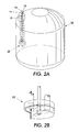
- Figure 2A is an exemplary perspective of a representative container or alternatively a source of particles, and sampling device or alternatively a sampler apparatus of the present invention.
- Figure 2B is a perspective of exemplary valving associated with the sampling device within the container, and adapted to sample small amounts of material from the container or source of particles of the present invention.
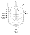
- Figure 3 shows an exemplary configuration of a sample analysis apparatus or port with associated lines and adapted for receipt, conditioning, analysis, and discard of the sample aliqout or material in embodiments of the present invention.
- Figure 4 shows an exemplary configuration of a representative in-line sonication cell the present invention.
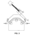
- Figure 5 shows an exemplary configuration of a reversible liquid pump of the present invention illustrating in embodiments a representative quick response shut-off start-up feature.
- Figure 6 shows another exemplary configuration of a reversible liquid pump of the present invention illustrating in embodiments another representative or alternative quick response shut-off start-up feature.
- the sonication can be accomplished, for example, with at least one ultrasonic member.
- the at least one ultrasonic member or plurality of ultrasonic members can be controlled by any suitable ultrasonic power source, and preferably a high powered ultrasonic source, such as a high powered ultrasonic welding source.
- the at least one ultrasonic member can be, for example, in embodiments from one to about 10 ultrasonic horns, and preferably from about 3 to about 8, and most preferably from about 4 to about 6 ultrasonic horns.
- the ultrasonic member or members function to firstly, separate guest or sub-particles, such as toner surface additives, charge control or flow control additives, and the like materials, from the surface of the host or first particles, such as toner particles, and secondly, to suspend the separated sub-particles in the liquid phase.
- guest or sub-particles such as toner surface additives, charge control or flow control additives, and the like materials
- the sub-particle suspensions that is the sonicated liquid phase containing the suspended sub-particles
- an electrically pulsed energy input is used to produce, for example, up and down movement of an exemplary four horn ultrasonic array.
- the diameter and geometry of the ultrasonic horn tip is preferably carefully chosen along with the sample tube configuration, such as a centrifuge tube, to optimize energy dispersion and the ultrasonic separation and surface particle stripping process.
- the process of the present invention can preferably further include separating the first particles from the liquid phase in the resulting sonicated mixture.
- the basis for this separation preference resides in a belief that the analysis is easier and more accurate.
- the separation step may for certain target analytes or for certain system configurations, the need for a separation or separations of particulates from the liquid phase may be obviated and unnecessary.
- the separation of the first particles from the liquid phase in the resulting sonicated mixture can be conveniently accomplished by known separation methodologies, for example, centrifugation, filtration, countercurrent distribution, such as fluid flow fractionation, or combinations thereof, and the like known liquid or solid particle-liquid phase and particle-particle phase separation methodologies.
- the process of the present invention can further comprise analyzing the liquid p hase for d issolved or suspended analytes which are solubilized or dispersed into the liquid phase from the surface of the first particles during the sonication procedure.
- the liquid can be, for example, an aqueous liquid, a non-aqueous liquid, a supercritical fluid, a miscible mixture of liquids, an immiscible mixture of liquids, and mixtures thereof, and like combinations.
- the second particles are preferably liberated from the surface of the first particles during sonication.
- the method of the present invention can further comprise analyzing the liquid phase for third particles and wherein the third particles can in certain instances be liberated from the surface of the first particles or the second particles during sonication.
- the third particles preferably are smaller than the second particles and the second particles have smaller third particles on the surface of the second particles.
- the second particles are known in many industries and technology areas as performance additives, and alternatively or additionally known as, for example, surface additives.
- Surface additives for example, in the xerographic imaging technology area can include charge control additives which regulate the charging properties of the toner or developers used in the xerographic process.
- surface additives can include flow additives which generally improve the flow and often the cleaning or removal or other properties of the toner or developer particles.
- the suspension of first particles can further comprise the inclusion of at least one surfactant in the suspension prior to sonication of the mixture.
- the surfactant can have any known h ydrophobe-lipophobe balance ( H LB ) which is effective in achieving the objectives of the present invention, for example, in suspending or dispersing host-guest particle compositions, and for facilitating the analysis of post sonication separated guest particle suspensions or dispersion.
- HLB h ydrophobe-lipophobe balance
- a suitable surfactant HLB can be over a broad known range, for example, of from about 0 to about 18 units, preferably with an HLB of from about 2 to about 15 units, and most preferably an HLB of from about 3 to about 14 units.
- the selection of the surfactant and its concomitant HLB will turn, for example, on the nature of the host-guest particle combination, on the relationship of the particle combination upon the matrices used to formulate a host-guest particle suspension, and upon the analytical result or results desired by the operator-analyst.
- the surfactant can be used in any suitable amount, for example: as used in various particle formulations as in commercial products or experimental formulations; to achieve a stable host-guest particle suspension at the outset of the analysis to facilitate handling and analysis; or to achieve a stable post-sonication separated guest particle suspension or dispersion.
- Suitable surfactant amounts can be, for example in analyzing toner surface additives, from about 1 to about 10 weight percent and preferably from about 2 to about 5 weight percent based on the weight of the suspended toner particles. It is readily apparent to one of ordinary skill in the art that the surfactant or emulsifier level or concentration can vary over a wide range, for example, from very low concentrations of a bout several parts-per-million or less to very highly concentrated surfactant formulations of about 70 to 99 weight percent based on the total weight of the formulation.
- the first particles can be present in the suspension, for example, in an amount of from about 0.1 to about 20 weight percent, preferably from about 1 to about 10 weight percent, and more preferably from about 2 to about 5 weight percent based on the total weight of the suspension. Other first particle weight percentages can be selected depending upon the analytical information desired and the other objectives of the analysis of the present invention.
- the first particles as host-guest particles can be comprised of, for example, a host toner particle composition with at least one guest particle type as the surface additive.
- the first particles can also be comprised of a host-guest developer composition comprised of guest toner composition and host carrier particles.
- the first particles can be comprised carrier particles and the second particles can be the toner particles and the third particles can be the surface additives on the surface of the toner particles.
- the first particles can be, for example, obtained from a liquid immersion developer composition, for example, either with or without the liquid carrier present.
- the first particles can be a pharmaceutical dosage form, such assolids, liquids, gels, foams, emulsions, microemulsions, suspensions, such as tablets, crushed tablets, powders, capsules, and the like formulations, which can be suspended, dispersed or appropriately dissolved in a liquid medium.
- particle refers to any discrete unit of material structure including those known entities with size ranges within the size domains of molecular, colloidal, microscopic, or macroscopic measurement.
- Particles of the present invention can include separable solid, liquid, or gaseous entities, and related or alternative entities, and mixtures thereof, such as finely divided solid, liquid, or gas particulates, powders, droplets, bubbles, and the like material dispositions.
- the present invention in embodiments can be applied to the analysis of host-guest particle combinations or associations including but not limited to, for example, solid-solid, solid-liquid, liquid-solid, liquid-liquid, solid-gas, gas-solid, liquid-gas, gas-liquid, and the like material dispositions.
- Alternative entities can include for example, foams, gels, slurries, emulsions, microemulsion, miniemulsions, molecular aggregrates, high molecular weight molecular solutions and dispersions, and the like.
- the method of the present invention can further include correlating the measured amount of suspended or dispersed guest particles in the liquid phase with the surface blending procedures used to prepare the host-guest particles.
- an apparatus comprising:
- the sonicator can be, for example, at least one ultrasonic member and a high powered ultrasonic welding source controller, and the at least one ultrasonic member can be, for example, from 3 to about 10 ultrasonic horns.
- the second analyzer can, for example, analyze the liquid phase for dissolved analytes solubilized from the surface of the first particles by the sonicator. It is readily apparent to one of ordinary skill in the art from a complete understanding of the invention that the second particles can be liberated from the surface of the first particles during sonication.
- toner and the like related first particles which were free of second particle surface treatments were sonicated for various intervals of time and intensities of ultrasound with the result that the untreated particles liberated little or no second particles.
- untreated first particles do not substantially decompose or degrade under the sonication or subsequent separation or analysis conditions of the present invention and therefore do not confound the analysis of second particles obtained by stripping the second particles from the surface of the first particles which have been previously surface treated.
- the apparatus of the present invention can be further adapted, for example, to analyze the liquid phase for third particles and wherein the third particles are liberated from the surface of the first particles, the second particles, or both the first particles and second particles during sonication.
- an apparatus comprising:
- a sample sonicating station (20) for example, as shown in Figure 3 can include one or more Mixers (30), an incoming sample/outgoing rinse line (22).
- the sample sonication station (20) may for example, include ports for introducing an inert gas (24) such as, nitrogen, water (26) and an electrolytic solution (28).
- the sample sonifcation station may further include, for example, a drain (36) and a probe (34).
- a sample sonicating station (20) embodiment can include a partial or complete enclosure which can partially or fully isolate the sonication station to further enhance the performance and utility of the present invention.
- isolation of the sonication chamber refers to and can include, for example: acoustic isolation, that is to reduce or eliminate any noise or audible interference generated by the ultrasound or associated mechanicals or sample processing; environmental isolation, that is, to reduce or eliminate any stray or extraneous emissions for the station or samples under analysis, such as vapors, plumes, spills, and the like effluents from the sonication station.
- acoustic isolation that is to reduce or eliminate any noise or audible interference generated by the ultrasound or associated mechanicals or sample processing
- environmental isolation that is, to reduce or eliminate any stray or extraneous emissions for the station or samples under analysis, such as vapors, plumes, spills, and the like effluents from the sonication station.
- the above mentioned isolation and abatement can be accomplished in embodiments, for example, by enclosing the sonication station in a chamber of PLEXIGLAS® or similar material enclosures, and which chamber or chambers can include for example
- the chamber can include or be situated in a known fume hood or fume removal system which system can be adapted to abate potentially noxious or toxic effluents arising from the samples or sample processing, and optionally to continuously clear the head-space or areas near the samples from potential extraneous contaminants.
- the chamber can include known insulation materials which materials adapt the sonicating station to maintaining a desired temperature regime.
- the chamber can include known heating or cooling elements adapted to maintain or manipulate the temperature and operating conditions within the sonication chamber and sonication station, for example, analogically or digitally programmably with a thermostat and associated switch and relay connections.
- Heating or cooling elements can include, for example, know air conditioners for conditioning the atmosphere, such as the temperature and optionally the humidity within the chamber.
- the sample tubes or the sample holder block can be heated or cooled as desired to maintain, regulate or otherwise manipulate the temperature of the samples within the chamber.
- the present invention in embodiments provides an apparatus comprising:
- the sonicator can have a power source adapted to precisely convert electrical energy to mechanical energy and thereafter divide and deliver the mechanical energy in equal amounts or measure to two or more horn members and consequently to the an appropriately situated sample.
- the present invention can further comprise an enclosure s ituated a bout the sonicator, to form for example, a chamber, and which enclosure is adapted to provide internal and external isolation of the apparatus, samples and sample processing from the surrounding environment.
- the enclosure contains effluents and prevents their escape into the surrounding environment.
- the enclosure blocks external or environmental influents and prevents their intrusion into the enclosed sonicating chamber an precludes sample contamination and confounding of the analytical results.
- station as used herein broadly and generally refers to, for example, any sample handling or information processing, or loci or module, contained or embodied within the apparatus and method of the present invention.
- Figure 1 shows a flow chart that illustrates, in embodiments, some main stages applied in an exemplary system, apparatus, and method, of the present invention.
- the system and apparatus can embody, a sequence (10) including but not limited to:
- FIG. 2A is an exemplary perspective of a representative sampling container (10) in embodiments of the present invention, and includes, for example, a sampling device (22), containint for example, a sampling aport (14) and drainage port (18) an automated sample preparation-analysis-diagnostic system ( 20 ), which can include a robot sample handling system ( 22 ), a robot "hand" tool (23) attached to a robot auto-sampler arm (24 ) adapted to progammably select from sample tube holder ( 26 ) and advance individual sample tubes ( 25) to the various stations in the system, such as a toner weigh station ( 28 ), a weigh station ( 30 ) for taring, surfactant and liquid phase addition, a sample mixing station ( 32 ) including for example a vibratory or vortex mixer apparatus, a sonication station ( 34 ) which can include, for example, the workstation shown in Figure 3, a centrifugation station ( 36 ), a supernatant analysis station ( 38 ) which can include one or more of the
- the aforementioned system components are preferably connected and fully integrated with a system control module ( 46 ) which can ensure seamless interaction of components and continuous operation of the system and can include a communications linkage to and between individual system components and optionally includes an external communications linkage, for example, to a network which connections can provide, for example, system status, results, and alert information to a remote operator.
- the robotic hand tool can be configured to hold a centrifuge tube, and can be adapted to hold virtual any comparably sized tube, jar, bottle, and the like containers by, for example, including an inner liner of VITON® elastomer (not shown) which material is found for example, in fuser roll applications.
- the VITON® liner provides a superior container grip and also provides a non-stick surface which avoids contaminant attachment or fouling.
- Figure 3 shows an exemplary configuration of the sonicating members in the sonication station of Figure 2. More specifically, Figure 3 shows a multi-probe ultrasonic workstation ( 34) of the present invention including, for example, an optional PLEXIGLA S ® or the like dust proof enclosure (not shown), a sample block ( 36 ) for receiving and securely retaining from a preceding station, by way of robotic or manual transfer, one or more sample vials or tubes ( 38 ). The samples in tubes( 38 ) are individually and respectively acted upon by ultrasonic horn members ( 40 ).
- a multi-probe ultrasonic workstation 34 of the present invention including, for example, an optional PLEXIGLA S ® or the like dust proof enclosure (not shown)
- a sample block ( 36 ) for receiving and securely retaining from a preceding station, by way of robotic or manual transfer, one or more sample vials or tubes ( 38 ).
- the samples in tubes( 38 ) are individually and respectively acted upon by ultrasonic horn members ( 40
- Multiple horn members ( 40) can be attached by any suitable means, such as a precision machined and countersunk screw or tapping ( 42) to multiplexed horn member ( 44 ) which member ( 44 ) is known and commercially available and which horn member ( 44 ) is known to be useful by itself, for example, to accomplish ultrasonic press welding of sheet materials.
- the horn member ( 44) is connected to power source converter ( 46 ) which converts electrical source energy ( 48 ) to ultrasonic mechanical energy which is transferred to the horn members ( 40 ) and thereafter dissipated into the samples contained in tubes ( 38 ) to effect the stripping of surface constituents from host particles.
- the foregoing componentry can be conveniently supported and properly aligned, for example, on stand (50) or an equivalent structure.
- the sample block ( 36 ), in embodiments, can be proximally delivered to horn members ( 40 ) by an elevator or similar lift means, such as a worm gear ( 60 ), which lift provides precision vertical displacement ( 52 ) of the sample block to enable either ultrasonication of samples when elevated or robot or manual access and sample interchange when depressed.
- the lift means or elevator is preferably attached to a servo-motor (not shown) and which motor is preferably electronically linked to the system control module ( 46 ) of Figure 2 to coordinate the placement sample block for appropriate operations and to optionally preclude the operation of the ultrasonic horns ( 40) in the absence of, for example, a complete set of sample tubes ( 36 ).
- Robotics can be employed to move samples to and from the various processing stations or analysis stations in the system.
- a robot can be used to tare a sample or centrifuge tube and cap combination at a weigh station.
- the robot removes the cap from the tarred sample vial and a powdered target sample, such as a toner or any other suitable solid, is placed into the tube.
- a powdered target sample such as a toner or any other suitable solid
- the cap is placed back atop the sample tube and the tube is reweighed and the amount of powder by difference from the tare is computed and recorded.
- the cap is removed and a prescribed quantity of surfactant solution is added to the tube and then recapped.
- a constant vortex mixing for a prescribed time wets the toner.
- the cap is removed and the tube is placed along with 3 other tubes beneath the four ultrasonic horns.
- the horns when energized can move up and down in regular pulses, to systematically and controllably effect the separation of the surface additive from the solid particle, such as a surface additive treated toner formulation.
- the ultrasonic horn tips can be constructed of, for example, titanium or other suitably hard metal or metals to avoid damage from hard or abrasive solids for example, toner additives, such as magnetites and titanias.
- the horns can be coated with a suitable protective coating, such as a inert polymer, diamond film, or other equivalent and suitably inert material, to further protect the horns from, for example, corrosion or material deposition, and the like potential changes in the sample or the horn members.
- the tube After centrifugation, the tube is transported to the final station at which the cap is removed and the liquid phase is aspirated from the sample vial or tube into the analytical instrument or instruments of choice for analysis of the liquid phase material.
- the analytical tool is, for example, an Inductively Coupled Plasma (ICP) unit.
- ICP Inductively Coupled Plasma
- the particle suspensions formed in the present invention ultrasonic step are so complete and stable, ICP analysis results from the inventive ultrasonic step can be duplicated many times over and with high precision and accuracy.
- Other analytical instruments can be used in addition to, or in place of, an ICP to carry out other analyses.
- a centrifuged supernatant or liquid phase could be robotically injected into a high performance liquid chromatography (HPLC) or gas chromatography (GC) unit to separate, identify, and quantify the soluble or insoluble components contained in the liquid phase.
- HPLC high performance liquid chromatography
- GC gas chromatography
- the graph shows an exemplary relation between adhesion force measurements, in terms of surface remainder silicon dioxide, that is guest particle SiO 2 remaining on the surface of host toner particles, as obtained with the present invention and solid area density (SAD) measurements obtained with images prepared from toner formulations with surface additives at various levels of surface treatment and adhesion.
- SAD solid area density
- a dvantages of the p resent invention include but are not limited to, for example, reduced sample analysis time, for example by a factor of from about 1.5 to about 10 fold; reduced sample size, for example, by from about 1.5 to about 10 fold compared to conventional ultrasonic sample sizes; providing a excellent screening tool for product development and product formulation, for example, situating and understanding the influence of surface additive constituents or contaminants; and the like advantages.
- advantages of the present invention include, for example: improved spatial design involving the linear array of ultrasonic horns and a robotic hand design which can universally grip various sizes and shapes of sample-centrifuge tubes; ultrasonic horns constructed of titanium or related metals, alloys, or include protective coating to improve wear of the ultrasonic horn tip; and a software data analysis and feedback mechanism to provide real-time adjustments in the parameters used for the host-guest particle separation and analysis.
- a 1 ml sample of an emulsion aggregation slurry with an average particle size distribution of 5.8-microns was analyzed using a Layson cell/Multisizer meaurement system.
- the sample was collected with a standard sampling device, transferred into a sample collection cup and rinsed .
- the sample was transported to the lab, diluted using an electrolytic solution, sonicated with a Branson device @ 25-Watts / 20kHz / 4-sec., and analyzed, yielding particle size measurements of from about 5.78 to about 5.83 microns. This process was repeated three times requiring an analysis time of about 1.5 hours.
- a 1 ml sample of an emulsion aggregation slurry with an average particle size distribution of 5.8-microns was tested using the sample extraction device in combination with a Masterflex, peristaltic pump with a manually actuated quick release feature.
- the sampling device suspended into a reactor vessel- in open position was used to extract a 1 ml sample of the slurry into a collection cup.
- the device was placed in the closed position and back-flushed utilizing the quick release feature on the peristaltic pump, with de-ionized water and nitrogen as the purge material.
- the extracted sample was then, diluted using an electrolytic solution, sonicated with a Branson device @ 25-Watts / 20kHz / 4-sec.) to simulate proposed sonication flow cell, and analyzed using aLayson Cell/Multisizer, yielding particle size measurements of from about 5.78 to about 5.82 microns. This process was repeated three times requiring an analysis time of about 0.75 hours. Major benefits are in the material handling of the sample, and the speed at which a result is obtained, allowing for more precise process control.
Landscapes
- Chemical & Material Sciences (AREA)
- Dispersion Chemistry (AREA)
- Physics & Mathematics (AREA)
- Health & Medical Sciences (AREA)
- Life Sciences & Earth Sciences (AREA)
- Analytical Chemistry (AREA)
- Biochemistry (AREA)
- General Health & Medical Sciences (AREA)
- General Physics & Mathematics (AREA)
- Immunology (AREA)
- Pathology (AREA)
- Sampling And Sample Adjustment (AREA)
Abstract
flush the system free of residual aliqout contamination.
Description
- The present invention is directed to a multi-horn ultrasonic agitator system which enables precise control of ultrasonic energy output from the horns and which system permits the a nalysis of, for example, liquid and solid phases, and small surface additive constituents (guest particles) residing on larger sized particulates (host particles). The present invention also provides automated robotic control and sample handling for efficient and automatic operation. The present invention provides methods and apparatuses for host and guest particle separation or host and guest particle extraction. The present invention provides an analytical tool to characterize the amount of guest surface additive(s) on and off the host or main particles, such as toners versus the amount of surface additive irrevocably impacted on the surface of the main particles. The resulting data can be readily correlated to host particle, guest particle, or subparticle performance and associative states or dispositions, such as toner and developer imaging performance. Thus it is readily apparent to one of ordinary skill in the art that embodiments of the present invention are readily adaptable to other marking formulations and other marking materials, and related consumable materials, such as, replenishers, liquid inks or developers, photoactive pigments and surface treated photoactive pigments, photoreceptors, fuser rolls constituents, backer rolls, fuser oils, cleaning formulations, papers or transparency stock, such as high quality or specialty receivers, "T"-shirt transfer compositions and components, and the like materials. It is also readily apparent to one of ordinary skill in the art that embodiments of the present invention are readily adaptable to other analytical technological endeavors, for example, pharmaceutical dosage form formulation and analysis, agri-product formulation and analysis, particulate and fiber forensic analysis, and like applications.
- In embodiments, the system and methods of present invention provide unexpected benefits and superior productivity performance levels to analysts or operators, for example, in facilitating unique or high volume sample analysis and result obtention, and in enabling sample of analysis of liquid suspended particulate materials and without the n eed for caustic o r corrosive reagents to p repare d issolved analytes, for example hydrofluoric acid solutions for ion coupled plasma (ICP) analysis of inorganic and organo-metallic materials
- Embodiments of the present invention, include:
- A system for analyzing particles comprising:
- a source of solid particles;
- a sampler apparatus attached to and integral with the source of solid particles which apparatus is adapted to enable removal of small amounts of sample material from the source;
- a sonication cell connected to the sampling apparatus which sonication cell receives, optionally conditions, and sonicates the small amounts of sample material;
- a sample analysis apparatus connected to the sonication cell which sample analysis apparatus is adapted to receive, optionally further condition, and analyze the resulting sonicated sample received from the sonication cell; and
- a liquid pump and liquid carrying lines adapted to:
- withdraw aliqouts from the source;
- convey a withdrawn aliqout to the sonication cell and sample analysis apparatus; and
- flush the system free of residual aliqout contamination; and
A method comprising:
- periodically removing with a reversible peristaltic pump a sample of a liquid dispersion of solid particles from a container;
- sonicating the sample for a time; and
- analyzing the particles contained in the resulting sonicated sample.
-
- In embodiments the present invention provides a system for analyzing particles comprising:
- a source of solid particles, such as a liquid container or chemical reactor which contains a liquid dispersion of solid particles;
- a sampler apparatus attached to and integral with the source of solid particles which apparatus is adapted to enable removal of small amounts of sample material from the source;
- a sonication cell connected to the sampling apparatus which sonication cell receives, optionally conditions, and sonicates the small amounts of sample material;
- a sample analysis apparatus connected to the sonication cell which sample analysis apparatus is adapted to receive, optionally further condition, and analyze the resulting sonicated sample received from the sonication cell; and
- a liquid pump and liquid carrying lines adapted to:
- withdraw aliqouts, for example, in predetermined volumes of liquid sample containing particles, from the source;
- convey a withdrawn aliqout to the sonication cell and sample analysis apparatus; and
- flush the system, including the sonication cell, sample analysis cell apparatus, and carrying lines free of residual aliqout or particulate contamination.
-
- In embodiments, the source of solid particles can be, for example, an emulsion-aggregation polymerization process reactor used to form solid particles. The sonication cell is designed to sonicate the sample material at, for example, from about 5 to about 75 kHz and from about 0.1 to about 500 watts and for a duration of from about 0.1 to about 7200 seconds.
- The system of the present invention can be configured so that the sonication cell further conditions the sample material, for example, with the addition of a dilutent liquid, such as water or low molecular weight alcohol such as methanol and the like immiscible liquids, for example, in amounts of from about 5 to about 500 weight percent based on the weight of the sample material. The system of the present invention can be configured so that the sonication cell further conditions the sample material, for example, with the addition of at least one surfactant compound in an amount of from about 0.01 to about 30 weight percent based on the weight of the sample material. The system of the present invention can be configured so that the sample analysis apparatus conditions the s ample by diluting the s ample with a miscible liquid, treating with ionic media, for example, an electrolyte solution, such as a 1 to 10 weight percent sodium chloride in water, removing air, for example, by vacuum, and replacing the vacated atmosphere with an inert gas, such as nitrogen or argon, or combinations of the foregoing conditioning modifications, and as illustrated herein, reference the working examples.
- In embodiments the present invention provides a method for analyzing particulate materials comprising:
- periodically removing with a reversible peristaltic pump a sample of a liquid dispersion of solid particles from a container;
- sonicating the sample for a time; and
- analyzing the particles contained in the resulting sonicated sample.
-
- Figure 1 is a flow diagram and schematic which illustrates main components and stages of the particle analysis system, apparatus, and method, in embodiments of the present invention. A container or source of
particles 10, such as a chemical reactor or mixer vessel, containing at some time in a manufacture process a particulate suspension or dispersion is connected to with the appropriate lines or plumbing to a sampling device or alternatively asampler apparatus 20. Thecontainer 10 is fitted with a sampler apparatus orport 50 adapted to controllably remove small aliqouts of material from the reactor. - Figure 2A is an exemplary perspective of a representative container or alternatively a source of particles, and sampling device or alternatively a sampler apparatus of the present invention.
- Figure 2B is a perspective of exemplary valving associated with the sampling device within the container, and adapted to sample small amounts of material from the container or source of particles of the present invention.
- Figure 3 shows an exemplary configuration of a sample analysis apparatus or port with associated lines and adapted for receipt, conditioning, analysis, and discard of the sample aliqout or material in embodiments of the present invention.
- Figure 4 shows an exemplary configuration of a representative in-line sonication cell the present invention.
- Figure 5 shows an exemplary configuration of a reversible liquid pump of the present invention illustrating in embodiments a representative quick response shut-off start-up feature.
- Figure 6 shows another exemplary configuration of a reversible liquid pump of the present invention illustrating in embodiments another representative or alternative quick response shut-off start-up feature.
- In embodiments, the sonication can be accomplished, for example, with at least one ultrasonic member. The at least one ultrasonic member or plurality of ultrasonic members can be controlled by any suitable ultrasonic power source, and preferably a high powered ultrasonic source, such as a high powered ultrasonic welding source. The at least one ultrasonic member can be, for example, in embodiments from one to about 10 ultrasonic horns, and preferably from about 3 to about 8, and most preferably from about 4 to about 6 ultrasonic horns. The ultrasonic member or members function to firstly, separate guest or sub-particles, such as toner surface additives, charge control or flow control additives, and the like materials, from the surface of the host or first particles, such as toner particles, and secondly, to suspend the separated sub-particles in the liquid phase. Because of the small size and the surface characteristics of the sub-particles, the sub-particle suspensions, that is the sonicated liquid phase containing the suspended sub-particles, is typically quite stable for considerable periods of time, for example, from about 1 minute to about 1 year, and thereby permits convenient manipulation, such as separation from host particles, and analysis thereof as exemplified and illustrated in embodiments of the present invention In the present invention an electrically pulsed energy input is used to produce, for example, up and down movement of an exemplary four horn ultrasonic array. The diameter and geometry of the ultrasonic horn tip is preferably carefully chosen along with the sample tube configuration, such as a centrifuge tube, to optimize energy dispersion and the ultrasonic separation and surface particle stripping process.
- In embodiments the process of the present invention can preferably further include separating the first particles from the liquid phase in the resulting sonicated mixture. Although not wanting to be limited by theory the basis for this separation preference resides in a belief that the analysis is easier and more accurate. However, with advances in modern analytical instrumentation the separation step may for certain target analytes or for certain system configurations, the need for a separation or separations of particulates from the liquid phase may be obviated and unnecessary. The separation of the first particles from the liquid phase in the resulting sonicated mixture can be conveniently accomplished by known separation methodologies, for example, centrifugation, filtration, countercurrent distribution, such as fluid flow fractionation, or combinations thereof, and the like known liquid or solid particle-liquid phase and particle-particle phase separation methodologies.
- The process of the present invention, in embodiments, can further comprise analyzing the liquid p hase for d issolved or suspended analytes which are solubilized or dispersed into the liquid phase from the surface of the first particles during the sonication procedure. The liquid can be, for example, an aqueous liquid, a non-aqueous liquid, a supercritical fluid, a miscible mixture of liquids, an immiscible mixture of liquids, and mixtures thereof, and like combinations. In embodiments, the second particles are preferably liberated from the surface of the first particles during sonication. The method of the present invention can further comprise analyzing the liquid phase for third particles and wherein the third particles can in certain instances be liberated from the surface of the first particles or the second particles during sonication. In embodiments the third particles preferably are smaller than the second particles and the second particles have smaller third particles on the surface of the second particles. The second particles are known in many industries and technology areas as performance additives, and alternatively or additionally known as, for example, surface additives. Surface additives, for example, in the xerographic imaging technology area can include charge control additives which regulate the charging properties of the toner or developers used in the xerographic process. Similarly surface additives can include flow additives which generally improve the flow and often the cleaning or removal or other properties of the toner or developer particles.
- In embodiments of the process of the present invention, the suspension of first particles can further comprise the inclusion of at least one surfactant in the suspension prior to sonication of the mixture. The surfactant can have any known h ydrophobe-lipophobe balance ( H LB ) which is effective in achieving the objectives of the present invention, for example, in suspending or dispersing host-guest particle compositions, and for facilitating the analysis of post sonication separated guest particle suspensions or dispersion. A suitable surfactant HLB can be over a broad known range, for example, of from about 0 to about 18 units, preferably with an HLB of from about 2 to about 15 units, and most preferably an HLB of from about 3 to about 14 units. It is readily appreciated and understood that the selection of the surfactant and its concomitant HLB will turn, for example, on the nature of the host-guest particle combination, on the relationship of the particle combination upon the matrices used to formulate a host-guest particle suspension, and upon the analytical result or results desired by the operator-analyst. The surfactant can be used in any suitable amount, for example: as used in various particle formulations as in commercial products or experimental formulations; to achieve a stable host-guest particle suspension at the outset of the analysis to facilitate handling and analysis; or to achieve a stable post-sonication separated guest particle suspension or dispersion. Suitable surfactant amounts can be, for example in analyzing toner surface additives, from about 1 to about 10 weight percent and preferably from about 2 to about 5 weight percent based on the weight of the suspended toner particles. It is readily apparent to one of ordinary skill in the art that the surfactant or emulsifier level or concentration can vary over a wide range, for example, from very low concentrations of a bout several parts-per-million or less to very highly concentrated surfactant formulations of about 70 to 99 weight percent based on the total weight of the formulation.
- The first particles can be present in the suspension, for example, in an amount of from about 0.1 to about 20 weight percent, preferably from about 1 to about 10 weight percent, and more preferably from about 2 to about 5 weight percent based on the total weight of the suspension. Other first particle weight percentages can be selected depending upon the analytical information desired and the other objectives of the analysis of the present invention. In embodiments, the first particles as host-guest particles can be comprised of, for example, a host toner particle composition with at least one guest particle type as the surface additive. The first particles can also be comprised of a host-guest developer composition comprised of guest toner composition and host carrier particles. Alternatively, in an embodiment the first particles can be comprised carrier particles and the second particles can be the toner particles and the third particles can be the surface additives on the surface of the toner particles. In embodiments the first particles can be, for example, obtained from a liquid immersion developer composition, for example, either with or without the liquid carrier present. In embodiments the first particles can be a pharmaceutical dosage form, such assolids, liquids, gels, foams, emulsions, microemulsions, suspensions, such as tablets, crushed tablets, powders, capsules, and the like formulations, which can be suspended, dispersed or appropriately dissolved in a liquid medium.
- As used herein "particle" refers to any discrete unit of material structure including those known entities with size ranges within the size domains of molecular, colloidal, microscopic, or macroscopic measurement. Particles of the present invention, whether the host, guest, or other particles, can include separable solid, liquid, or gaseous entities, and related or alternative entities, and mixtures thereof, such as finely divided solid, liquid, or gas particulates, powders, droplets, bubbles, and the like material dispositions. The present invention in embodiments can be applied to the analysis of host-guest particle combinations or associations including but not limited to, for example, solid-solid, solid-liquid, liquid-solid, liquid-liquid, solid-gas, gas-solid, liquid-gas, gas-liquid, and the like material dispositions. Alternative entities can include for example, foams, gels, slurries, emulsions, microemulsion, miniemulsions, molecular aggregrates, high molecular weight molecular solutions and dispersions, and the like. In an embodiment of the present invention there is provided a method comprising:
- ultrasonicating an aqueous suspension comprised of at least one surfactant and surface treated toner particles;
- separating the toner particles from the aqueous phase in the resulting mixture; and
- measuring the liquid phase for dissolved or suspended surface treatment material stripped from the surface of the surface treated toner particles.
- In still other embodiments of the present invention, there is provided a particle surface analytical method comprising:
- sonicating an liquid suspension comprised of host particles surface treated with guest particles;
- separating the host particles from the liquid phase in the resulting mixture; and
- measuring the liquid phase for suspended guest particles stripped from the surface of the surface host particles.
-
- In embodiments the method of the present invention can further include correlating the measured amount of suspended or dispersed guest particles in the liquid phase with the surface blending procedures used to prepare the host-guest particles. In an embodiment of the present invention there is provided an apparatus comprising:
- a sonicator adapted to sonicate a liquid suspension of first particles; and
- a first analyzer adapted to analyze the sonicated liquid phase for second particles.
-
- The sonicator can be, for example, at least one ultrasonic member and a high powered ultrasonic welding source controller, and the at least one ultrasonic member can be, for example, from 3 to about 10 ultrasonic horns. In embodiments the second analyzer can, for example, analyze the liquid phase for dissolved analytes solubilized from the surface of the first particles by the sonicator. It is readily apparent to one of ordinary skill in the art from a complete understanding of the invention that the second particles can be liberated from the surface of the first particles during sonication. As a control experiment, for example, toner and the like related first particles which were free of second particle surface treatments were sonicated for various intervals of time and intensities of ultrasound with the result that the untreated particles liberated little or no second particles. Thus it is apparent that untreated first particles do not substantially decompose or degrade under the sonication or subsequent separation or analysis conditions of the present invention and therefore do not confound the analysis of second particles obtained by stripping the second particles from the surface of the first particles which have been previously surface treated. The apparatus of the present invention can be further adapted, for example, to analyze the liquid phase for third particles and wherein the third particles are liberated from the surface of the first particles, the second particles, or both the first particles and second particles during sonication.
- In an exemplary embodiment of the present invention there is provided an apparatus comprising:
- a sample preparation station adapted to generate first particle dispersions, for example, by combining a minor measured amounts of a first particle sample as the disperse phase and major measured a mounts of a liquid or equivalent medium as the continuous phase;
- an ultrasonication station comprised of a plurality of ultrasonic horns adapted to sonicate the first particle's dispersions;
- a sample separation station adapted to separate first particles from the liquid or equivalent suspending or dispersing medium in the resulting sonicated dispersion;
- a sample analysis station adapted to analyze the resulting separated liquid or equivalent medium for any liberated second particles;
- a data analysis station adapted to analyze the resulting liberated second particles data from the sample analysis station; and
- a programmable robot adapted to continuously advance a sample container, for example, with an auto sampler and the like devices, from a blank or empty sample container or tube storage, to the sample preparation station, to the ultrasonication station, to the sample separation station, to the sample analysis station, to the data analysis station, and optionally to a sample retention or discard station.
-
- It is readily appreciated by one of ordinary skill in the art that the present invention can be embodied in a single sonicating station or apparatus. Thus for example, a sample sonicating station (20), for example, as shown in Figure 3 can include one or more Mixers (30), an incoming sample/outgoing rinse line (22). The sample sonication station (20) may for example, include ports for introducing an inert gas (24) such as, nitrogen, water (26) and an electrolytic solution (28). The sample sonifcation station may further include, for example, a drain (36) and a probe (34). Additionally or alternatively, a sample sonicating station (20) embodiment can include a partial or complete enclosure which can partially or fully isolate the sonication station to further enhance the performance and utility of the present invention. "Isolation" of the sonication chamber refers to and can include, for example: acoustic isolation, that is to reduce or eliminate any noise or audible interference generated by the ultrasound or associated mechanicals or sample processing; environmental isolation, that is, to reduce or eliminate any stray or extraneous emissions for the station or samples under analysis, such as vapors, plumes, spills, and the like effluents from the sonication station. The above mentioned isolation and abatement can be accomplished in embodiments, for example, by enclosing the sonication station in a chamber of PLEXIGLAS® or similar material enclosures, and which chamber or chambers can include for example, one or more sound absorbent or abating materials. Additionally or alternatively, the chamber can include or be situated in a known fume hood or fume removal system which system can be adapted to abate potentially noxious or toxic effluents arising from the samples or sample processing, and optionally to continuously clear the head-space or areas near the samples from potential extraneous contaminants. Additionally or alternatively, the chamber can include known insulation materials which materials adapt the sonicating station to maintaining a desired temperature regime. Additionally or alternatively, the chamber can include known heating or cooling elements adapted to maintain or manipulate the temperature and operating conditions within the sonication chamber and sonication station, for example, analogically or digitally programmably with a thermostat and associated switch and relay connections. Heating or cooling elements can include, for example, know air conditioners for conditioning the atmosphere, such as the temperature and optionally the humidity within the chamber. Alternatively, the sample tubes or the sample holder block can be heated or cooled as desired to maintain, regulate or otherwise manipulate the temperature of the samples within the chamber.
- The present invention in embodiments provides an apparatus comprising:
- a sonicator adapted to sonicate at least one liquid suspension of first particles with pulsed ultrasonic energy.
-
- In view of the forgoing discussion it is readily a ppreciated that the sonicator can have a power source adapted to precisely convert electrical energy to mechanical energy and thereafter divide and deliver the mechanical energy in equal amounts or measure to two or more horn members and consequently to the an appropriately situated sample. The present invention can further comprise an enclosure s ituated a bout the sonicator, to form for example, a chamber, and which enclosure is adapted to provide internal and external isolation of the apparatus, samples and sample processing from the surrounding environment. The enclosure contains effluents and prevents their escape into the surrounding environment. Similarly, the enclosure blocks external or environmental influents and prevents their intrusion into the enclosed sonicating chamber an precludes sample contamination and confounding of the analytical results.
- The term "station" as used herein broadly and generally refers to, for example, any sample handling or information processing, or loci or module, contained or embodied within the apparatus and method of the present invention.
- Referring to the Figures, Figure 1 shows a flow chart that illustrates, in embodiments, some main stages applied in an exemplary system, apparatus, and method, of the present invention. The system and apparatus can embody, a sequence (10) including but not limited to:
- sample preparation (10); sample sonication station (20); a sample mixing device (30), for example separating solid particles or a precipitate
- resulting from centrifugation from the liquid or supernatant phase; a
- sampling d evice (50), for example w herein the s upernatant is a nalyzed
- for material arising from the surface of the first particles or original particulate sample with, for example, known methods and
- instrumentation, such as ICP, liquid chromatography, gas chromatography, and the like analytical methods; and a flow cell for in-line analysis of a sample.
-
- Figure 2A is an exemplary perspective of a representative sampling container (10) in embodiments of the present invention, and includes, for example, a sampling device (22), containint for example, a sampling aport (14) and drainage port (18) an automated sample preparation-analysis-diagnostic system ( 20 ), which can include a robot sample handling system ( 22 ), a robot "hand" tool (23) attached to a robot auto-sampler arm (24 ) adapted to progammably select from sample tube holder ( 26 ) and advance individual sample tubes ( 25) to the various stations in the system, such as a toner weigh station ( 28 ), a weigh station ( 30 ) for taring, surfactant and liquid phase addition, a sample mixing station ( 32 ) including for example a vibratory or vortex mixer apparatus, a sonication station ( 34 ) which can include, for example, the workstation shown in Figure 3, a centrifugation station ( 36 ), a supernatant analysis station ( 38 ) which can include one or more of the aforementioned analytical or diagnostic instruments, such as an ICP, an optional sample or tube collection or regeneration station ( 40 ), and a data recording and analysis station ( 44 ) adapted to record and analyze the data obtained from the supernatant analysis station ( 38 ), including for example, a programmable computer with a memory capable of receiving, storing, processing, generating, and displaying results from operating on the input data. The aforementioned system components are preferably connected and fully integrated with a system control module ( 46 ) which can ensure seamless interaction of components and continuous operation of the system and can include a communications linkage to and between individual system components and optionally includes an external communications linkage, for example, to a network which connections can provide, for example, system status, results, and alert information to a remote operator. In embodiments the robotic hand tool can be configured to hold a centrifuge tube, and can be adapted to hold virtual any comparably sized tube, jar, bottle, and the like containers by, for example, including an inner liner of VITON® elastomer (not shown) which material is found for example, in fuser roll applications. The VITON® liner provides a superior container grip and also provides a non-stick surface which avoids contaminant attachment or fouling.
- Figure 3 shows an exemplary configuration of the sonicating members in the sonication station of Figure 2. More specifically, Figure 3 shows a multi-probe ultrasonic workstation ( 34) of the present invention including, for example, an optional PLEXIGLA
S ® or the like dust proof enclosure (not shown), a sample block ( 36 ) for receiving and securely retaining from a preceding station, by way of robotic or manual transfer, one or more sample vials or tubes ( 38 ). The samples in tubes( 38 ) are individually and respectively acted upon by ultrasonic horn members ( 40 ). Multiple horn members ( 40) can be attached by any suitable means, such as a precision machined and countersunk screw or tapping ( 42) to multiplexed horn member ( 44 ) which member ( 44 ) is known and commercially available and which horn member ( 44 ) is known to be useful by itself, for example, to accomplish ultrasonic press welding of sheet materials. The horn member ( 44) is connected to power source converter ( 46 ) which converts electrical source energy ( 48 ) to ultrasonic mechanical energy which is transferred to the horn members ( 40 ) and thereafter dissipated into the samples contained in tubes ( 38 ) to effect the stripping of surface constituents from host particles. The foregoing componentry can be conveniently supported and properly aligned, for example, on stand (50) or an equivalent structure. The sample block ( 36 ), in embodiments, can be proximally delivered to horn members ( 40 ) by an elevator or similar lift means, such as a worm gear ( 60 ), which lift provides precision vertical displacement ( 52 ) of the sample block to enable either ultrasonication of samples when elevated or robot or manual access and sample interchange when depressed. The lift means or elevator is preferably attached to a servo-motor (not shown) and which motor is preferably electronically linked to the system control module ( 46 ) of Figure 2 to coordinate the placement sample block for appropriate operations and to optionally preclude the operation of the ultrasonic horns ( 40) in the absence of, for example, a complete set of sample tubes ( 36 ). - Robotics can be employed to move samples to and from the various processing stations or analysis stations in the system. As an initial step, a robot can be used to tare a sample or centrifuge tube and cap combination at a weigh station. Next the robot removes the cap from the tarred sample vial and a powdered target sample, such as a toner or any other suitable solid, is placed into the tube. The cap is placed back atop the sample tube and the tube is reweighed and the amount of powder by difference from the tare is computed and recorded. At the next station, the cap is removed and a prescribed quantity of surfactant solution is added to the tube and then recapped. At the next station, a constant vortex mixing for a prescribed time wets the toner. At the next station the cap is removed and the tube is placed along with 3 other tubes beneath the four ultrasonic horns. The horns when energized can move up and down in regular pulses, to systematically and controllably effect the separation of the surface additive from the solid particle, such as a surface additive treated toner formulation.
- The ultrasonic horn tips can be constructed of, for example, titanium or other suitably hard metal or metals to avoid damage from hard or abrasive solids for example, toner additives, such as magnetites and titanias. Alternatively, the horns can be coated with a suitable protective coating, such as a inert polymer, diamond film, or other equivalent and suitably inert material, to further protect the horns from, for example, corrosion or material deposition, and the like potential changes in the sample or the horn members. After the ultrasonication step, the tube is recapped and then delivered to the centrifuge station, where centrifugation is accomplished. After centrifugation, the tube is transported to the final station at which the cap is removed and the liquid phase is aspirated from the sample vial or tube into the analytical instrument or instruments of choice for analysis of the liquid phase material. For toner applications, the analytical tool is, for example, an Inductively Coupled Plasma (ICP) unit. G enerally, I CP analysis results obtained from suspensions are not very reproducible. However, because the particle suspensions formed in the present invention ultrasonic step are so complete and stable, ICP analysis results from the inventive ultrasonic step can be duplicated many times over and with high precision and accuracy. Other analytical instruments can be used in addition to, or in place of, an ICP to carry out other analyses. For example, in a non-toner application, a centrifuged supernatant or liquid phase could be robotically injected into a high performance liquid chromatography (HPLC) or gas chromatography (GC) unit to separate, identify, and quantify the soluble or insoluble components contained in the liquid phase.
- Referring to Figure 4 the graph shows an exemplary relation between adhesion force measurements, in terms of surface remainder silicon dioxide, that is guest particle SiO2 remaining on the surface of host toner particles, as obtained with the present invention and solid area density (SAD) measurements obtained with images prepared from toner formulations with surface additives at various levels of surface treatment and adhesion. The data as plotted and fitted with the line shown in the Figure provides a high level of correlation of, for example, solid area density (SAD) as measured with a densitometer from solid area printed images and expressed in density units with the residual SiO2 remaining on the surface of various sonicated SiO2 surface treated toner samples.
- Other a dvantages of the p resent invention include but are not limited to, for example, reduced sample analysis time, for example by a factor of from about 1.5 to about 10 fold; reduced sample size, for example, by from about 1.5 to about 10 fold compared to conventional ultrasonic sample sizes; providing a excellent screening tool for product development and product formulation, for example, situating and understanding the influence of surface additive constituents or contaminants; and the like advantages. Other advantages of the present invention include, for example: improved spatial design involving the linear array of ultrasonic horns and a robotic hand design which can universally grip various sizes and shapes of sample-centrifuge tubes; ultrasonic horns constructed of titanium or related metals, alloys, or include protective coating to improve wear of the ultrasonic horn tip; and a software data analysis and feedback mechanism to provide real-time adjustments in the parameters used for the host-guest particle separation and analysis.
- A 1 ml sample of an emulsion aggregation slurry with an average particle size distribution of 5.8-microns was analyzed using a Layson cell/Multisizer meaurement system. The sample was collected with a standard sampling device, transferred into a sample collection cup and rinsed . The sample was transported to the lab, diluted using an electrolytic solution, sonicated with a Branson device @ 25-Watts / 20kHz / 4-sec., and analyzed, yielding particle size measurements of from about 5.78 to about 5.83 microns. This process was repeated three times requiring an analysis time of about 1.5 hours.
- A 1 ml sample of an emulsion aggregation slurry with an average particle size distribution of 5.8-microns was tested using the sample extraction device in combination with a Masterflex, peristaltic pump with a manually actuated quick release feature. The sampling device, suspended into a reactor vessel- in open position was used to extract a 1 ml sample of the slurry into a collection cup. The device was placed in the closed position and back-flushed utilizing the quick release feature on the peristaltic pump, with de-ionized water and nitrogen as the purge material. The extracted sample was then, diluted using an electrolytic solution, sonicated with a Branson device @ 25-Watts / 20kHz / 4-sec.) to simulate proposed sonication flow cell, and analyzed using aLayson Cell/Multisizer, yielding particle size measurements of from about 5.78 to about 5.82 microns. This process was repeated three times requiring an analysis time of about 0.75 hours. Major benefits are in the material handling of the sample, and the speed at which a result is obtained, allowing for more precise process control.
Claims (10)
- A system for analyzing particles comprising:a source of solid particles;a sampler apparatus attached to and integral with the source of solid particles which apparatus is adapted to enable removal of small amounts of sample material from the source;a sonication cell connected to the sampling apparatus which sonication cell receives, optionally conditions, and sonicates the small amounts of sample material;a sample analysis apparatus connected to the sonication cell which sample analysis apparatus is adapted to receive, optionally further condition, and analyze the resulting sonicated sample received from the sonication cell; anda liquid pump and liquid carrying lines adapted to:withdraw aliqouts from the source;convey a withdrawn aliqout to the sonication cell and sample analysis apparatus; andflush the system free of residual aliqout contamination.
- The system of claim 1, wherein the source of solid particles is an emulsion-aggregation polymerization process reactor forming solid particles.
- The system of claim 1, wherein the sampler apparatus removes small amounts of sample material from the source in amounts of from about 0.1 mL to about 10 mL.
- The system of claim 1, wherein the sonication cell sonicates the sample material at from about 5 to about 75 kHz, and from about 0.1 to about 500 watts and for a duration of from about 0.1 to about 7200 seconds.
- The system of claim 4, further comprising wherein the sonication cell further conditions the sample material with the addition of a dilutent liquid in an amount of from about 5 to about 500 weight percent based on the weight of the sample material.
- The system of claim 4, further comprising wherein the sonication cell further conditions the sample material with the addition of at least one surfactant compound in an amount of from about 0.01 to about 30 weight percent based on the weight of the sample material.
- The system of claim 1, wherein further comprising wherein the sample analysis apparatus conditions the sample by diluting the sample with a miscible liquid, treating with ionic media, removing air and replacing with an inert gas, or combinations thereof.
- The system of claim 1, wherein the liquid pump is a quick response reversible peristaltic pump.
- The system of claim 1, wherein the liquid carrying lines are corrosion resistant tubing and which tubing is resistant to distortion or deformation under internal pressures of from about 10 psi to about 1,000 psi.
- A method comprising:periodically removing with a reversible pump a sample of a liquid dispersion of solid particles from a container;sonicating the sample for a time; andanalyzing the particles contained in the resulting sonicated sample.
Applications Claiming Priority (2)
| Application Number | Priority Date | Filing Date | Title |
|---|---|---|---|
| US13864 | 1998-01-27 | ||
| US10/013,864 US6931950B2 (en) | 2001-12-13 | 2001-12-13 | System and processes for particulate analysis |
Publications (2)
| Publication Number | Publication Date |
|---|---|
| EP1319938A1 true EP1319938A1 (en) | 2003-06-18 |
| EP1319938B1 EP1319938B1 (en) | 2009-03-18 |
Family
ID=21762184
Family Applications (1)
| Application Number | Title | Priority Date | Filing Date |
|---|---|---|---|
| EP02027985A Expired - Lifetime EP1319938B1 (en) | 2001-12-13 | 2002-12-13 | Method for analyzing particulate materials |
Country Status (6)
| Country | Link |
|---|---|
| US (1) | US6931950B2 (en) |
| EP (1) | EP1319938B1 (en) |
| JP (1) | JP2003194685A (en) |
| BR (1) | BR0205186B1 (en) |
| CA (1) | CA2413680C (en) |
| DE (1) | DE60231587D1 (en) |
Families Citing this family (26)
| Publication number | Priority date | Publication date | Assignee | Title |
|---|---|---|---|---|
| JP2002202241A (en) * | 2000-10-30 | 2002-07-19 | Sysmex Corp | Electrolytic solution for particle measuring instrument |
| JP5069905B2 (en) | 2003-01-21 | 2012-11-07 | アプテュイト (ウエスト ラファイエット)、エルエルシー | Novel co-crystallization |
| US7113265B1 (en) | 2003-05-20 | 2006-09-26 | The United States Of America As Represented By The Administrator Of The National Aeronautics And Space Administration | Powder handling device for analytical instruments |
| WO2005089375A2 (en) | 2004-03-12 | 2005-09-29 | S.S.C.I., Inc. | Screening for solid forms by ultrasound crystallization and cocrystallization using ultrasound |
| US7034549B2 (en) * | 2004-03-31 | 2006-04-25 | The United States Of America As Represented By The Secretary Of The Navy | Device to detect and measure the concentration and characterization of airborne conductive or dielectric particles |
| US20050235740A1 (en) * | 2004-04-27 | 2005-10-27 | Guido Desie | Method to improve the quality of dispersion formulations |
| US20050255254A1 (en) * | 2004-05-13 | 2005-11-17 | Guido Desie | Method to improve the quality of dispersion formulations |
| EP1889029A1 (en) * | 2005-05-24 | 2008-02-20 | Basf Aktiengesellschaft | Method for determining residues in plastics |
| US20080202259A1 (en) * | 2005-06-07 | 2008-08-28 | Basf Aktiengesellschaft | Method For Determining Pesticide Residues in Soil or Plant Material |
| US20090179341A1 (en) * | 2005-12-21 | 2009-07-16 | Mccausland Linda | Sonication methods for screening and preparing solid forms |
| JP5085741B2 (en) * | 2008-10-08 | 2012-11-28 | 新日本製鐵株式会社 | Metal material with excellent corrosion resistance |
| US8477295B2 (en) | 2009-05-07 | 2013-07-02 | Solum, Inc. | Automated soil measurement device |
| US8144319B2 (en) * | 2009-05-07 | 2012-03-27 | Solum, Inc. | Automated soil measurement device |
| US20110094320A1 (en) * | 2009-10-26 | 2011-04-28 | Liang Hong | Method for evaluating de-agglomeration/coagulation stability of agglomerates materials |
| US20120103077A1 (en) * | 2010-10-29 | 2012-05-03 | Solum, Inc. | Microsampling Nutrient Measurement |
| US9146223B1 (en) * | 2012-08-03 | 2015-09-29 | Monsanto Technology Llc | Automated soil measurement device |
| US9291545B1 (en) | 2012-09-06 | 2016-03-22 | Monsanto Technology Llc | Self-filling soil processing chamber with dynamic extractant volume |
| CN102866041B (en) * | 2012-09-11 | 2015-02-25 | 山东斯巴特电力驱动技术有限公司 | Oil-water gas online sampling system |
| US9459194B2 (en) | 2013-03-14 | 2016-10-04 | Cardio Metrix | Apparatuses, processes, and systems for measuring particle size distribution and concentration |
| KR102313961B1 (en) | 2016-04-14 | 2021-10-15 | 어플라이드 머티어리얼스, 인코포레이티드 | 30 NM In-Line LPC Testing and Cleaning of Semiconductor Processing Equipment |
| WO2017184972A1 (en) * | 2016-04-22 | 2017-10-26 | Protein Dynamic Solutions Llc | Liquid handling system and method |
| PT109563B (en) * | 2016-08-02 | 2020-09-23 | Hovione Farmaciencia Sa | METHOD FOR IMPROVING THE DEVELOPMENT AND VALIDATION OF ANALYTICAL AND SAMPLE PREPARATION METHODS FOR ACCURATE AND REPRODUCTIVE MEASUREMENT OF PARTICLE SIZE |
| US10989472B2 (en) | 2017-04-27 | 2021-04-27 | Xerox Corporation | Method, apparatus and system for fluid cooling of toner dryer |
| CN111189752B (en) * | 2020-03-19 | 2024-06-21 | 瑞德(新乡)路业有限公司 | Intelligent catering oil smoke supervision device with lifting structure |
| CN114002026B (en) * | 2021-11-10 | 2022-12-06 | 中船重工安谱(湖北)仪器有限公司 | Externally-hung gas sampling probe for vehicle-mounted gas detection instrument |
| CN116008383A (en) * | 2022-12-30 | 2023-04-25 | 杭州谱育科技发展有限公司 | Detection method based on LA technology |
Citations (9)
| Publication number | Priority date | Publication date | Assignee | Title |
|---|---|---|---|---|
| JPS6184544A (en) * | 1984-10-02 | 1986-04-30 | Mitsubishi Heavy Ind Ltd | Sampling method for analysis of solid-liquid slurry |
| JPS62228139A (en) * | 1986-03-28 | 1987-10-07 | Shimadzu Corp | Sedimentation type particle size distribution measuring device |
| WO1989007766A1 (en) * | 1988-02-19 | 1989-08-24 | Micromeritics Instrument Corporation | Automatic sample feeder for suspended samples |
| US5439288A (en) * | 1994-02-01 | 1995-08-08 | General Signal Corporation | Automated small volume recirculator for particle analysis |
| US5695720A (en) * | 1995-04-03 | 1997-12-09 | B.C. Research Inc. | Flow analysis network apparatus |
| US5918272A (en) * | 1996-04-12 | 1999-06-29 | General Electric Company | Magnetic and ultrasonic discriminator for particle size distribution analyzer |
| JP2000155088A (en) * | 1998-11-20 | 2000-06-06 | Horiba Ltd | Draining method for sample liquid and washing liquid in particle diameter distribution measuring device by light scattering method |
| JP2001183360A (en) * | 1999-12-24 | 2001-07-06 | Shimadzu Corp | Water quality analyzer |
| US6318158B1 (en) * | 2000-03-01 | 2001-11-20 | Coulter International Corp. | Sample preparation and delivery system employing external sonicator |
Family Cites Families (14)
| Publication number | Priority date | Publication date | Assignee | Title |
|---|---|---|---|---|
| US4199546A (en) * | 1978-03-16 | 1980-04-22 | Chemplex Company | Manufacture and recovery of olefin polymer particles |
| US4415011A (en) * | 1981-11-02 | 1983-11-15 | Isco, Inc. | Sample collector |
| US4419496A (en) * | 1982-02-22 | 1983-12-06 | The Dow Chemical Company | Particle agglomeration in rubber latices |
| JPS61225656A (en) * | 1985-03-29 | 1986-10-07 | Toshiba Corp | Sample inspector |
| US4639356A (en) * | 1985-11-05 | 1987-01-27 | American Cyanamid Company | High technology ceramics with partially stabilized zirconia |
| US4850707A (en) * | 1986-06-06 | 1989-07-25 | Massachusetts Institute Of Technology | Optical pulse particle size analyzer |
| US4741841A (en) * | 1986-06-16 | 1988-05-03 | Industrial Filter & Pump Mfg. Co. | Method and apparatus for particle separation |
| JPS63314606A (en) * | 1987-06-18 | 1988-12-22 | Fanuc Ltd | Controller for articulated robot |
| US5400665A (en) * | 1991-09-25 | 1995-03-28 | Cetac Technologies Incorporated | Sample introduction system for inductively coupled plasma and other gas-phase, or particle, detectors utilizing an enclosed filter solvent removal system, and method of use |
| US5259254A (en) * | 1991-09-25 | 1993-11-09 | Cetac Technologies, Inc. | Sample introduction system for inductively coupled plasma and other gas-phase, or particle, detectors utilizing ultrasonic nebulization, and method of use |
| US5441071A (en) * | 1994-05-04 | 1995-08-15 | Mclane Research Laboratories, Inc. | Automated water sample collecting system |
| US5840026A (en) * | 1994-09-21 | 1998-11-24 | Medrad, Inc. | Patient specific dosing contrast delivery systems and methods |
| US6175409B1 (en) * | 1999-04-02 | 2001-01-16 | Symyx Technologies, Inc. | Flow-injection analysis and variable-flow light-scattering methods and apparatus for characterizing polymers |
| US6156208A (en) * | 1998-05-20 | 2000-12-05 | Institute Guilfoyle | Ferrographic method |
-
2001
- 2001-12-13 US US10/013,864 patent/US6931950B2/en not_active Expired - Fee Related
-
2002
- 2002-12-06 CA CA002413680A patent/CA2413680C/en not_active Expired - Fee Related
- 2002-12-11 JP JP2002359317A patent/JP2003194685A/en not_active Withdrawn
- 2002-12-13 EP EP02027985A patent/EP1319938B1/en not_active Expired - Lifetime
- 2002-12-13 DE DE60231587T patent/DE60231587D1/en not_active Expired - Lifetime
- 2002-12-13 BR BRPI0205186-9A patent/BR0205186B1/en not_active IP Right Cessation
Patent Citations (9)
| Publication number | Priority date | Publication date | Assignee | Title |
|---|---|---|---|---|
| JPS6184544A (en) * | 1984-10-02 | 1986-04-30 | Mitsubishi Heavy Ind Ltd | Sampling method for analysis of solid-liquid slurry |
| JPS62228139A (en) * | 1986-03-28 | 1987-10-07 | Shimadzu Corp | Sedimentation type particle size distribution measuring device |
| WO1989007766A1 (en) * | 1988-02-19 | 1989-08-24 | Micromeritics Instrument Corporation | Automatic sample feeder for suspended samples |
| US5439288A (en) * | 1994-02-01 | 1995-08-08 | General Signal Corporation | Automated small volume recirculator for particle analysis |
| US5695720A (en) * | 1995-04-03 | 1997-12-09 | B.C. Research Inc. | Flow analysis network apparatus |
| US5918272A (en) * | 1996-04-12 | 1999-06-29 | General Electric Company | Magnetic and ultrasonic discriminator for particle size distribution analyzer |
| JP2000155088A (en) * | 1998-11-20 | 2000-06-06 | Horiba Ltd | Draining method for sample liquid and washing liquid in particle diameter distribution measuring device by light scattering method |
| JP2001183360A (en) * | 1999-12-24 | 2001-07-06 | Shimadzu Corp | Water quality analyzer |
| US6318158B1 (en) * | 2000-03-01 | 2001-11-20 | Coulter International Corp. | Sample preparation and delivery system employing external sonicator |
Non-Patent Citations (4)
| Title |
|---|
| PATENT ABSTRACTS OF JAPAN vol. 010, no. 256 (P - 493) 2 September 1986 (1986-09-02) * |
| PATENT ABSTRACTS OF JAPAN vol. 012, no. 095 (P - 681) 29 March 1988 (1988-03-29) * |
| PATENT ABSTRACTS OF JAPAN vol. 2000, no. 09 13 October 2000 (2000-10-13) * |
| PATENT ABSTRACTS OF JAPAN vol. 2000, no. 24 11 May 2001 (2001-05-11) * |
Also Published As
| Publication number | Publication date |
|---|---|
| US20030110871A1 (en) | 2003-06-19 |
| BR0205186A (en) | 2004-07-20 |
| EP1319938B1 (en) | 2009-03-18 |
| CA2413680C (en) | 2007-02-06 |
| CA2413680A1 (en) | 2003-06-13 |
| JP2003194685A (en) | 2003-07-09 |
| BR0205186B1 (en) | 2012-12-11 |
| US6931950B2 (en) | 2005-08-23 |
| DE60231587D1 (en) | 2009-04-30 |
Similar Documents
| Publication | Publication Date | Title |
|---|---|---|
| EP1319938B1 (en) | Method for analyzing particulate materials | |
| EP2270469B1 (en) | Method of analyzing particle size distribution of particles in metal material | |
| US11555823B2 (en) | Medical analysis method | |
| Madden et al. | Coalescence frequencies in agitated liquid‐liquid systems | |
| CA2463940A1 (en) | Automated system and method for processing specimens to extract samples for both liquid-based and slide-based testing | |
| US6508104B1 (en) | Method for additive adhesion force particle analysis and apparatus thereof | |
| EP0478753A4 (en) | Automated molecular biology laboratory | |
| AU2018237575B2 (en) | System for mixing contents of containers and related methods of use | |
| US9039636B2 (en) | Devices and methods for enhanced cellular sample transfer | |
| Hackley et al. | Particle size analysis by laser diffraction spectrometry: application to cementitious powders | |
| US6598466B1 (en) | Method for additive adhesion force particle analysis and apparatus thereof | |
| AU758047B2 (en) | Improved method for mixing and processing specimen samples | |
| EP4383310A2 (en) | Systems for extracting analytes from a sample | |
| JPH03163357A (en) | Catecholamine analysis method and its analyzer | |
| Turner et al. | Surface chemistry interventions to control boiler tube fouling | |
| Dukhin et al. | Introduction to measurement methods | |
| US20190151852A1 (en) | Autosampler with ultrasonic bath for handling samples and standards with suspended nanoparticles | |
| Hodoroaba et al. | Techniques evaluation report for selection of characterisation methods | |
| Schäffer et al. | Inter-laboratory note. Automated large volume slurry preparation in slurry sampling electrothermal atomic absorption spectrometry | |
| KR20260055533A (en) | Source material stirring device for separating magnetic and non-magnetic impurities and source material stirring method | |
| Todd et al. | Fractionation of Mixed Solids by High-Voltage Electrophoresis. | |
| Kawaguchi et al. | Sample Preparation and the Characterization for Intratracheal Administration | |
| Klein et al. | Modular field-flow fractionation and dynamic laser light scattering system for size and molecular weight determination | |
| Melton | Development of a Rapid Analytical Method for Determining Asbestos in Water | |
| Sanjoh | PCMOS-Protein Crystallization Microfluidic Systems |
Legal Events
| Date | Code | Title | Description |
|---|---|---|---|
| PUAI | Public reference made under article 153(3) epc to a published international application that has entered the european phase |
Free format text: ORIGINAL CODE: 0009012 |
|
| AK | Designated contracting states |
Designated state(s): AT BE BG CH CY CZ DE DK EE ES FI FR GB GR IE IT LI LU MC NL PT SE SI SK TR |
|
| AX | Request for extension of the european patent |
Extension state: AL LT LV MK RO |
|
| 17P | Request for examination filed |
Effective date: 20031218 |
|
| AKX | Designation fees paid |
Designated state(s): DE FR GB |
|
| 17Q | First examination report despatched |
Effective date: 20061114 |
|
| RTI1 | Title (correction) |
Free format text: METHOD FOR ANALYZING PARTICULATE MATERIALS |
|
| GRAP | Despatch of communication of intention to grant a patent |
Free format text: ORIGINAL CODE: EPIDOSNIGR1 |
|
| GRAS | Grant fee paid |
Free format text: ORIGINAL CODE: EPIDOSNIGR3 |
|
| GRAA | (expected) grant |
Free format text: ORIGINAL CODE: 0009210 |
|
| AK | Designated contracting states |
Kind code of ref document: B1 Designated state(s): DE FR GB |
|
| REG | Reference to a national code |
Ref country code: GB Ref legal event code: FG4D |
|
| REF | Corresponds to: |
Ref document number: 60231587 Country of ref document: DE Date of ref document: 20090430 Kind code of ref document: P |
|
| PLBE | No opposition filed within time limit |
Free format text: ORIGINAL CODE: 0009261 |
|
| STAA | Information on the status of an ep patent application or granted ep patent |
Free format text: STATUS: NO OPPOSITION FILED WITHIN TIME LIMIT |
|
| 26N | No opposition filed |
Effective date: 20091221 |
|
| REG | Reference to a national code |
Ref country code: FR Ref legal event code: PLFP Year of fee payment: 14 |
|
| REG | Reference to a national code |
Ref country code: FR Ref legal event code: PLFP Year of fee payment: 15 |
|
| PGFP | Annual fee paid to national office [announced via postgrant information from national office to epo] |
Ref country code: DE Payment date: 20161121 Year of fee payment: 15 Ref country code: GB Payment date: 20161128 Year of fee payment: 15 Ref country code: FR Payment date: 20161121 Year of fee payment: 15 |
|
| REG | Reference to a national code |
Ref country code: DE Ref legal event code: R119 Ref document number: 60231587 Country of ref document: DE |
|
| GBPC | Gb: european patent ceased through non-payment of renewal fee |
Effective date: 20171213 |
|
| REG | Reference to a national code |
Ref country code: FR Ref legal event code: ST Effective date: 20180831 |
|
| PG25 | Lapsed in a contracting state [announced via postgrant information from national office to epo] |
Ref country code: FR Free format text: LAPSE BECAUSE OF NON-PAYMENT OF DUE FEES Effective date: 20180102 Ref country code: DE Free format text: LAPSE BECAUSE OF NON-PAYMENT OF DUE FEES Effective date: 20180703 |
|
| PG25 | Lapsed in a contracting state [announced via postgrant information from national office to epo] |
Ref country code: GB Free format text: LAPSE BECAUSE OF NON-PAYMENT OF DUE FEES Effective date: 20171213 |