EP1319890A2 - Vorrichtung zum Verdampfen und Überhitzen wenigstens eines Mediums sowie Brennstoffzellensystem - Google Patents
Vorrichtung zum Verdampfen und Überhitzen wenigstens eines Mediums sowie Brennstoffzellensystem Download PDFInfo
- Publication number
- EP1319890A2 EP1319890A2 EP02027418A EP02027418A EP1319890A2 EP 1319890 A2 EP1319890 A2 EP 1319890A2 EP 02027418 A EP02027418 A EP 02027418A EP 02027418 A EP02027418 A EP 02027418A EP 1319890 A2 EP1319890 A2 EP 1319890A2
- Authority
- EP
- European Patent Office
- Prior art keywords
- medium
- evaporator
- channel
- superheater
- throughflow
- Prior art date
- Legal status (The legal status is an assumption and is not a legal conclusion. Google has not performed a legal analysis and makes no representation as to the accuracy of the status listed.)
- Granted
Links
- 239000000446 fuel Substances 0.000 title claims abstract description 58
- 230000008016 vaporization Effects 0.000 title description 8
- 239000010410 layer Substances 0.000 claims description 116
- 238000010438 heat treatment Methods 0.000 claims description 88
- 238000006243 chemical reaction Methods 0.000 claims description 70
- 238000002156 mixing Methods 0.000 claims description 69
- 238000013021 overheating Methods 0.000 claims description 51
- 238000001704 evaporation Methods 0.000 claims description 29
- 230000004888 barrier function Effects 0.000 claims description 21
- 239000002356 single layer Substances 0.000 claims description 13
- 230000003197 catalytic effect Effects 0.000 claims description 12
- 238000012545 processing Methods 0.000 claims description 11
- 238000005516 engineering process Methods 0.000 claims description 10
- 239000002131 composite material Substances 0.000 claims description 9
- 239000011888 foil Substances 0.000 claims description 4
- 238000011144 upstream manufacturing Methods 0.000 claims description 3
- 239000000203 mixture Substances 0.000 description 49
- 238000000034 method Methods 0.000 description 31
- 230000008569 process Effects 0.000 description 28
- 239000003502 gasoline Substances 0.000 description 25
- XLYOFNOQVPJJNP-UHFFFAOYSA-N water Substances O XLYOFNOQVPJJNP-UHFFFAOYSA-N 0.000 description 24
- 239000001257 hydrogen Substances 0.000 description 20
- 229910052739 hydrogen Inorganic materials 0.000 description 20
- UFHFLCQGNIYNRP-UHFFFAOYSA-N Hydrogen Chemical compound [H][H] UFHFLCQGNIYNRP-UHFFFAOYSA-N 0.000 description 18
- 238000002485 combustion reaction Methods 0.000 description 18
- 230000008020 evaporation Effects 0.000 description 18
- 238000013461 design Methods 0.000 description 13
- 239000007789 gas Substances 0.000 description 13
- 239000000463 material Substances 0.000 description 10
- 239000002737 fuel gas Substances 0.000 description 9
- 239000003054 catalyst Substances 0.000 description 8
- 239000007788 liquid Substances 0.000 description 8
- 230000008901 benefit Effects 0.000 description 7
- 229930195733 hydrocarbon Natural products 0.000 description 7
- 150000002430 hydrocarbons Chemical class 0.000 description 7
- 239000004215 Carbon black (E152) Substances 0.000 description 6
- OKKJLVBELUTLKV-UHFFFAOYSA-N Methanol Chemical compound OC OKKJLVBELUTLKV-UHFFFAOYSA-N 0.000 description 6
- 230000003647 oxidation Effects 0.000 description 5
- 238000007254 oxidation reaction Methods 0.000 description 5
- 238000001816 cooling Methods 0.000 description 4
- 230000000694 effects Effects 0.000 description 4
- 238000004939 coking Methods 0.000 description 3
- -1 gasoline Chemical class 0.000 description 3
- 238000004519 manufacturing process Methods 0.000 description 3
- CURLTUGMZLYLDI-UHFFFAOYSA-N Carbon dioxide Chemical compound O=C=O CURLTUGMZLYLDI-UHFFFAOYSA-N 0.000 description 2
- UGFAIRIUMAVXCW-UHFFFAOYSA-N Carbon monoxide Chemical compound [O+]#[C-] UGFAIRIUMAVXCW-UHFFFAOYSA-N 0.000 description 2
- 230000033228 biological regulation Effects 0.000 description 2
- 238000009835 boiling Methods 0.000 description 2
- 229910002091 carbon monoxide Inorganic materials 0.000 description 2
- 238000009826 distribution Methods 0.000 description 2
- 238000005530 etching Methods 0.000 description 2
- 230000017525 heat dissipation Effects 0.000 description 2
- 239000012528 membrane Substances 0.000 description 2
- VNWKTOKETHGBQD-UHFFFAOYSA-N methane Chemical compound C VNWKTOKETHGBQD-UHFFFAOYSA-N 0.000 description 2
- 230000008092 positive effect Effects 0.000 description 2
- 239000000376 reactant Substances 0.000 description 2
- 239000000126 substance Substances 0.000 description 2
- 238000012546 transfer Methods 0.000 description 2
- 239000006200 vaporizer Substances 0.000 description 2
- 238000004378 air conditioning Methods 0.000 description 1
- QVGXLLKOCUKJST-UHFFFAOYSA-N atomic oxygen Chemical compound [O] QVGXLLKOCUKJST-UHFFFAOYSA-N 0.000 description 1
- 230000015572 biosynthetic process Effects 0.000 description 1
- 229910002092 carbon dioxide Inorganic materials 0.000 description 1
- 239000001569 carbon dioxide Substances 0.000 description 1
- 239000007795 chemical reaction product Substances 0.000 description 1
- 238000009833 condensation Methods 0.000 description 1
- 230000005494 condensation Effects 0.000 description 1
- 238000010276 construction Methods 0.000 description 1
- 230000001419 dependent effect Effects 0.000 description 1
- 238000005553 drilling Methods 0.000 description 1
- 238000004049 embossing Methods 0.000 description 1
- 150000002431 hydrogen Chemical class 0.000 description 1
- 125000004435 hydrogen atom Chemical group [H]* 0.000 description 1
- 239000007791 liquid phase Substances 0.000 description 1
- 238000005259 measurement Methods 0.000 description 1
- 229910052751 metal Inorganic materials 0.000 description 1
- 239000002184 metal Substances 0.000 description 1
- 238000003801 milling Methods 0.000 description 1
- 239000003345 natural gas Substances 0.000 description 1
- 230000007935 neutral effect Effects 0.000 description 1
- 239000007800 oxidant agent Substances 0.000 description 1
- 230000001590 oxidative effect Effects 0.000 description 1
- 239000001301 oxygen Substances 0.000 description 1
- 229910052760 oxygen Inorganic materials 0.000 description 1
- 238000002360 preparation method Methods 0.000 description 1
- 239000000047 product Substances 0.000 description 1
- 239000002994 raw material Substances 0.000 description 1
- 238000011946 reduction process Methods 0.000 description 1
- 238000002407 reforming Methods 0.000 description 1
- 230000001105 regulatory effect Effects 0.000 description 1
- 239000007858 starting material Substances 0.000 description 1
Images



Classifications
-
- H—ELECTRICITY
- H01—ELECTRIC ELEMENTS
- H01M—PROCESSES OR MEANS, e.g. BATTERIES, FOR THE DIRECT CONVERSION OF CHEMICAL ENERGY INTO ELECTRICAL ENERGY
- H01M8/00—Fuel cells; Manufacture thereof
- H01M8/06—Combination of fuel cells with means for production of reactants or for treatment of residues
- H01M8/0606—Combination of fuel cells with means for production of reactants or for treatment of residues with means for production of gaseous reactants
- H01M8/0612—Combination of fuel cells with means for production of reactants or for treatment of residues with means for production of gaseous reactants from carbon-containing material
-
- B—PERFORMING OPERATIONS; TRANSPORTING
- B01—PHYSICAL OR CHEMICAL PROCESSES OR APPARATUS IN GENERAL
- B01B—BOILING; BOILING APPARATUS ; EVAPORATION; EVAPORATION APPARATUS
- B01B1/00—Boiling; Boiling apparatus for physical or chemical purposes ; Evaporation in general
- B01B1/005—Evaporation for physical or chemical purposes; Evaporation apparatus therefor, e.g. evaporation of liquids for gas phase reactions
-
- F—MECHANICAL ENGINEERING; LIGHTING; HEATING; WEAPONS; BLASTING
- F22—STEAM GENERATION
- F22B—METHODS OF STEAM GENERATION; STEAM BOILERS
- F22B3/00—Other methods of steam generation; Steam boilers not provided for in other groups of this subclass
- F22B3/02—Other methods of steam generation; Steam boilers not provided for in other groups of this subclass involving the use of working media other than water
-
- F—MECHANICAL ENGINEERING; LIGHTING; HEATING; WEAPONS; BLASTING
- F22—STEAM GENERATION
- F22G—SUPERHEATING OF STEAM
- F22G1/00—Steam superheating characterised by heating method
-
- F—MECHANICAL ENGINEERING; LIGHTING; HEATING; WEAPONS; BLASTING
- F28—HEAT EXCHANGE IN GENERAL
- F28D—HEAT-EXCHANGE APPARATUS, NOT PROVIDED FOR IN ANOTHER SUBCLASS, IN WHICH THE HEAT-EXCHANGE MEDIA DO NOT COME INTO DIRECT CONTACT
- F28D9/00—Heat-exchange apparatus having stationary plate-like or laminated conduit assemblies for both heat-exchange media, the media being in contact with different sides of a conduit wall
- F28D9/0031—Heat-exchange apparatus having stationary plate-like or laminated conduit assemblies for both heat-exchange media, the media being in contact with different sides of a conduit wall the conduits for one heat-exchange medium being formed by paired plates touching each other
- F28D9/0043—Heat-exchange apparatus having stationary plate-like or laminated conduit assemblies for both heat-exchange media, the media being in contact with different sides of a conduit wall the conduits for one heat-exchange medium being formed by paired plates touching each other the plates having openings therein for circulation of at least one heat-exchange medium from one conduit to another
- F28D9/005—Heat-exchange apparatus having stationary plate-like or laminated conduit assemblies for both heat-exchange media, the media being in contact with different sides of a conduit wall the conduits for one heat-exchange medium being formed by paired plates touching each other the plates having openings therein for circulation of at least one heat-exchange medium from one conduit to another the plates having openings therein for both heat-exchange media
-
- F—MECHANICAL ENGINEERING; LIGHTING; HEATING; WEAPONS; BLASTING
- F28—HEAT EXCHANGE IN GENERAL
- F28F—DETAILS OF HEAT-EXCHANGE AND HEAT-TRANSFER APPARATUS, OF GENERAL APPLICATION
- F28F13/00—Arrangements for modifying heat-transfer, e.g. increasing, decreasing
- F28F13/06—Arrangements for modifying heat-transfer, e.g. increasing, decreasing by affecting the pattern of flow of the heat-exchange media
-
- B—PERFORMING OPERATIONS; TRANSPORTING
- B01—PHYSICAL OR CHEMICAL PROCESSES OR APPARATUS IN GENERAL
- B01J—CHEMICAL OR PHYSICAL PROCESSES, e.g. CATALYSIS OR COLLOID CHEMISTRY; THEIR RELEVANT APPARATUS
- B01J2219/00—Chemical, physical or physico-chemical processes in general; Their relevant apparatus
- B01J2219/00781—Aspects relating to microreactors
-
- B—PERFORMING OPERATIONS; TRANSPORTING
- B01—PHYSICAL OR CHEMICAL PROCESSES OR APPARATUS IN GENERAL
- B01J—CHEMICAL OR PHYSICAL PROCESSES, e.g. CATALYSIS OR COLLOID CHEMISTRY; THEIR RELEVANT APPARATUS
- B01J2219/00—Chemical, physical or physico-chemical processes in general; Their relevant apparatus
- B01J2219/00781—Aspects relating to microreactors
- B01J2219/00873—Heat exchange
-
- C—CHEMISTRY; METALLURGY
- C01—INORGANIC CHEMISTRY
- C01B—NON-METALLIC ELEMENTS; COMPOUNDS THEREOF; METALLOIDS OR COMPOUNDS THEREOF NOT COVERED BY SUBCLASS C01C
- C01B2203/00—Integrated processes for the production of hydrogen or synthesis gas
- C01B2203/12—Feeding the process for making hydrogen or synthesis gas
- C01B2203/1288—Evaporation of one or more of the different feed components
- C01B2203/1294—Evaporation by heat exchange with hot process stream
-
- F—MECHANICAL ENGINEERING; LIGHTING; HEATING; WEAPONS; BLASTING
- F28—HEAT EXCHANGE IN GENERAL
- F28D—HEAT-EXCHANGE APPARATUS, NOT PROVIDED FOR IN ANOTHER SUBCLASS, IN WHICH THE HEAT-EXCHANGE MEDIA DO NOT COME INTO DIRECT CONTACT
- F28D21/00—Heat-exchange apparatus not covered by any of the groups F28D1/00 - F28D20/00
- F28D2021/0019—Other heat exchangers for particular applications; Heat exchange systems not otherwise provided for
- F28D2021/0061—Other heat exchangers for particular applications; Heat exchange systems not otherwise provided for for phase-change applications
- F28D2021/0064—Vaporizers, e.g. evaporators
-
- F—MECHANICAL ENGINEERING; LIGHTING; HEATING; WEAPONS; BLASTING
- F28—HEAT EXCHANGE IN GENERAL
- F28F—DETAILS OF HEAT-EXCHANGE AND HEAT-TRANSFER APPARATUS, OF GENERAL APPLICATION
- F28F2260/00—Heat exchangers or heat exchange elements having special size, e.g. microstructures
- F28F2260/02—Heat exchangers or heat exchange elements having special size, e.g. microstructures having microchannels
-
- Y—GENERAL TAGGING OF NEW TECHNOLOGICAL DEVELOPMENTS; GENERAL TAGGING OF CROSS-SECTIONAL TECHNOLOGIES SPANNING OVER SEVERAL SECTIONS OF THE IPC; TECHNICAL SUBJECTS COVERED BY FORMER USPC CROSS-REFERENCE ART COLLECTIONS [XRACs] AND DIGESTS
- Y02—TECHNOLOGIES OR APPLICATIONS FOR MITIGATION OR ADAPTATION AGAINST CLIMATE CHANGE
- Y02E—REDUCTION OF GREENHOUSE GAS [GHG] EMISSIONS, RELATED TO ENERGY GENERATION, TRANSMISSION OR DISTRIBUTION
- Y02E60/00—Enabling technologies; Technologies with a potential or indirect contribution to GHG emissions mitigation
- Y02E60/30—Hydrogen technology
- Y02E60/50—Fuel cells
Definitions
- the present invention initially relates to a device for vaporizing and Overheating at least one medium according to the preamble of claim 1.
- the invention further relates to a fuel cell system according to the preamble of claim 23.
- Evaporators Devices for evaporating liquid media, or so-called Evaporators are used in various areas of technology, for example in the Air conditioning and cooling technology.
- An increasingly important area of Application is the fuel cell technology. Fuel cells have been around for a long time known and especially in the automotive industry in recent years Years has grown significantly in importance. Similar to how battery systems generate Fuel cells electrical energy by chemical means, the individual Reactants fed continuously and the reaction products continuously be dissipated.
- the between electrically neutral molecules or Atomic oxidation and reduction processes usually via a Membrane spatially separated.
- Such membranes have the ability to ionize direct, but retain gases.
- the electrons released during the oxidation can be conducted as electrical current through a consumer, for example the Electric motor of a motor vehicle.
- Hydrogen can be used as fuel and oxygen as oxidant. If you want the fuel cell with an easily available or easier to use storing fuel such as natural gas, methanol, gasoline, diesel or others Operate hydrocarbons, you have the hydrocarbon in one Device for generating or processing a fuel first convert into a hydrogen-rich gas.
- At least one reactor element of the device for generating or to prepare the fuel it is a Device for vaporizing the fuel used.
- the vaporizer has that Task to first evaporate the raw material for the fuel before this in vapor form for further treatment in the next Reactor element, for example a reformer, is initiated.
- DE-A-2 224 826 describes a method and a method Device for evaporating and overheating a medium, in the said case one cryogenic medium.
- the device for evaporation and overheating consists of two reaction stages, with a first reaction stage as an evaporator and a second reaction stage is designed as a superheater.
- the evaporator in The form of a heat exchanger initially has a throughflow device Passing through the medium to be evaporated. Furthermore, one Heating device provided for providing thermal energy. About the This is the heat energy provided by the heating device Medium flowing through evaporates. These are the Flow device and the heating device thermally coupled.
- the Downstream of the evaporator is another heat exchanger that functions as a Superheater takes over.
- the medium evaporated in the evaporator becomes in the superheater heated to a predetermined temperature level.
- the overheating is carried out in a similar manner to that of the evaporator.
- the Superheater via a superheater to provide thermal energy for overheating the one flowing through the throughflow device of the superheater Medium. They are also used in the heat exchanger designed as a superheater Flow device and the superheater thermally coupled.
- a disadvantage of the known solution is that the device for Evaporation and overheating is very large and therefore takes up a lot of space requires.
- the individual reaction stages of the device are spatial located far apart so that the medium inside the device is about appropriate line systems must be transported.
- this can be too Loss of pressure leads, as the medium sometimes has to travel long distances.
- additional ones are required according to the known teaching Items such as pumps, valves, and the like are required.
- the present invention is based on the cited prior art
- the task is based on a structurally simple device for vaporizing and Overheat at least one medium to provide, on the one hand a high Performance and, on the other hand, only a small space needs and can therefore be made compact. In particular, a additional mixing of at least two media will be possible.
- an apparatus for vaporizing and Overheating provided at least one medium, with at least two Reaction stages, with at least a first reaction stage as an evaporator at least partial evaporation of the at least one medium is formed with at least one throughflow device for passing the material to be evaporated Medium and with at least one heating device for providing Thermal energy for at least partially evaporating the Flow-through medium flowing through, the flow-through device is thermally coupled to the heating device and wherein at least one of the at least a first reaction stage in the direction of flow of the medium subsequent second reaction stage as a superheater for overheating the evaporated medium or to completely evaporate and overheat the partially evaporated medium is formed with at least one Flow-through device for passing the exiting from the evaporator Medium and with at least one overheating device for providing Thermal energy for overheating the flowing through the flow device Medium to a certain temperature or to completely evaporate the Medium and for overheating the medium to a certain temperature, wherein the flow device is thermally coupled to
- the device is characterized in that the at least an evaporator and the at least one superheater as a layer composite Single layers is formed that the flow device of the evaporator and the flow device of the superheater has at least one layer with at least one has a channel and that at least one layer of the flow device the evaporator with at least one layered heating device and at least one layer of the throughflow device of the superheater with at least one a layered superheater is connected.
- the device according to the invention is initially very powerful. Farther the device requires only a small amount of space, so that it is very compact can be trained. The device can therefore be advantageous anywhere there can be used where space is limited.
- the invention is not limited to a certain number of evaporators and / or overheating.
- a single evaporator be provided in the direction of flow of the medium to be evaporated individual superheater is connected downstream.
- device performance requirements can be multiple Evaporators and superheaters can be provided.
- the evaporators and / or Superheaters in series one after the other or also parallel to each other be connected. Any combinations of these are of course also exemplary described wiring arrangements possible.
- a basic idea of the present invention is that the at least one evaporator and the at least one superheater as a layer composite is formed from individual layers. This has a number of advantages. So it is on simple and therefore inexpensive way possible, the individual layers of the Evaporator or superheater initially to produce separately and then combine to form the respective reactor element. Furthermore can also the number of individual layers can be varied so that the individual Reactor elements can be adapted to the prevailing requirements can. The layered design of the individual components further achieved that good heat transfer between the individual Components is realized.
- the throughflow devices of the evaporator and the Superheater on at least one layer with a channel structure There is in everyone Flow device provided at least one channel.
- the invention is not limited to a certain number of channels. In the simplest case it points the flow device on a single channel. However, can also be advantageous several channels can be provided, which are then preferably parallel to one another are arranged. The more channels are provided, the greater the amount of Medium can be passed through the flow device at the same time become. On the one hand, this can significantly improve throughput.
- the space requirement of the evaporator or superheater can be reduced be reduced because the individual channels compared to a single channel can be much shorter.
- the invention is not limited to a specific embodiment and / or Arrangement of the channels in the flow devices limited. Rather can the channel structure have any dimension. In particular, the individual channels have any size and cross-sectional shape. To this The device according to the invention can be particularly simple and effectively adapt to any possible application.
- Each channel preferably has an entry area, a reaction area and an exit area. That area becomes the entry area understood, in which the medium enters the channel.
- the entrance area can be thereby also extend to a point at which a corresponding reaction starts.
- the exit area is analogous.
- Reaction area is understood to be the area of the channel in which most of the reaction takes place in the medium flowing through the channels.
- the boundaries between the individual areas are not tight, but fluent, so that reactions are already in the entrance area or can still occur in the exit area.
- the division of the Channels in the above areas only serve to roughly classify the channels.
- At least one layer of the Flow device of the evaporator with at least one layered Heating device is connected. This way it becomes a particularly simple one and efficient evaporation of the flowing through the flow device Medium reached.
- the invention is not limited to a specific number Flow-through layers and heater layers limited.
- the evaporator has a flow device layer and a heater layer that is thermally interconnected are coupled so that an optimal heat exchange between the Heating device and the one flowing through the throughflow device Medium can be done.
- more than one in each case Flow device layer are stacked on top of each other and that not after each flow device layer is followed by a heater layer. In the superheater can be constructed analogously.
- the device according to the invention for vaporizing and overheating at least A medium has a number of advantages. Doing so first to point out that with the device both individual media, as well Mixtures of media from two or more media evaporate or overheat can be.
- the vaporized Medium or mixture of media when leaving the superheater an even has a defined temperature.
- the Evaporator and the superheater are designed as independent reaction stages. That doesn't necessarily mean that vaporizers and superheaters are self-contained separate components must be available. Rather, it is also conceivable that the evaporator and the superheater are integrated in a single component. If the evaporator and the superheater are independent of each other Reaction stages are formed, this means that the individual reaction stages can be thermally insulated from each other. This makes good controllability of the individual components and high dynamics of the entire device guaranteed.
- the first reaction stage designed as an evaporator can advantageously serve to to heat the initially liquid medium up to a temperature range which the medium can evaporate.
- the second, designed as a superheater Reaction stage that the evaporator in the flow direction of the evaporated Medium is connected downstream, then preferably fine adjustable heating system the medium can be heated further. Preferably it will adjusted to an exactly maintainable temperature.
- the invention is not based on a specific configuration or arrangement of the Heating device and / or the overheating device limited.
- the heating device, or overheating device provided thermal energy electrically is produced.
- the provision of thermal energy by means of suitable heating elements, heating cartridges and the like.
- This Heating elements are then preferably in the layered heating device, or superheater.
- the heating device and / or the overheating device has a channel structure with at least one channel and that through the channels a corresponding heating medium flows through.
- the invention is self-evident not limited to the above two exemplary examples. Some non-exclusive examples of suitable designs for the The heating device and the overheating device will be described later the description explained in more detail.
- the device according to the invention can have an input distribution area to which liquid medium is fed from a supply line. On the The input distribution area is then the medium on the input area of the at least one channel of the at least one flow device of the distributed at least one evaporator. After passing through the reaction area of the channel, the evaporated medium is in via the outlet area of the channel open a media outlet. From there, the medium - depending on the design the device - enter another evaporator or superheater.
- the entrance area, or the entrance opening, or the entrance of the at least one channel of the throughflow opening of the superheater is also connected to the connected above evaporator outlet, so that through the adjacent Overpressure the already completely evaporated medium from the Evaporator in the superheater, or, if there are several subsequent evaporators, in the subsequent evaporator and from there in further reaction stages is pressed in, where it evaporates as completely as possible and by means of the Overheating device is set to the predetermined temperature.
- At least individual channels of individual flow devices can be advantageous different channel structures in the entry area and / or exit area and / or reaction area.
- the channels are made larger in the entry area or exit area are as in the reaction area.
- the number of channels in Entry area or exit area is smaller than in the reaction area is.
- one in the reaction area if possible large number of channels as small as possible is provided, which means a large Reaction surface is created.
- the entry areas and exit areas essentially to lead the medium to the reaction area, or to discharge the medium from the reaction area, it can be advantageous that the number of channels in these areas is smaller, with larger channel cross sections at the same time. This ensures that the medium easily in the reaction areas of the channels can enter or leave.
- the evaporator and / or the superheater using microstructure technology can be advantageous be trained. It is particularly provided that the at least one channel the flow device of the evaporator and / or superheater as a microchannel is trained.
- the design in microtechnology ensures that in the smallest space, a large number of microchannels can be realized Width and height are in the submillimeter range. In this way, the Evaporator and / or the superheater over high specific surfaces, that is a high ratio of channel surface area to channel volume.
- At least individual layers of the evaporator can and / or superheater can be designed as foils.
- the invention is not based on certain design forms or types of manufacture for the Layers limited, so that different techniques are used here can come.
- the individual layers, or channels are produced by means of process technologies such as those used in small structures can be used. This can be done using, for example Etching the channels out of the layers, by embossing or the like be made.
- the layered heating device of the evaporator have at least one channel for the passage of a heating medium.
- the heater is similar to that Flow device of the evaporator constructed, so that in this regard also reference is made to the above statements and reference is hereby made. If the heating device has a channel structure, the evaporation can of the medium flowing through the flow device in the following manner respectively.
- the layered heater and the layered Flow device are thermally coupled to each other, resulting in a good Heat exchange between the individual layers leads to that Heating medium which flows through the channels of the heating device transferring living heat energy to the medium to be evaporated. It can it be advantageous if the channels of the flow device and the channels of the Heating device have a different channel structure. That's the way it is for example conceivable that the channel cross sections of the channels of Heating device are larger than that due to a larger mass flow Channel cross sections of the channels in the flow device.
- the heating device according to the principle of a catalytic burner works.
- the channels are the Heating device coated with a catalyst material. If the channels are now flowed through with a medium containing the catalyst material reacts, this creates an exothermic reaction, which means that heat is released becomes. This heat can then be used to heat the medium to be evaporated be used.
- Such a configuration of the heating device is Particularly advantageous if the evaporator is in the low temperature range works up to about 400 ° C.
- the channels of the throughflow device and the Heating device to be aligned parallel to each other.
- the channels are aligned with one another in the cross-flow principle.
- the evaporator can be operated either in the cocurrent principle or in the countercurrent principle.
- the channels of the throughflow device and the However flows through the heating device in the countercurrent principle, or can be flowed through in the counterflow principle. This enables a special continuous, precisely controllable heating or evaporation of the Medium.
- the evaporator has at least one Has flow device for the medium to be evaporated.
- the evaporator can continue to be Mixing device for mixing in at least one further medium for addition have evaporating medium. In this way, a mixed media be produced, which is then evaporated.
- the device is in connection with the in the Introduction is used, namely that it Part of a device for generating / processing a fuel for a Fuel cell, it may be advantageous that a mixture of a Hydrocarbon, such as gasoline, and water is produced is then evaporated and overheated. Then can via the mixing device the corresponding mixture is adjusted according to the required ratio become.
- a Hydrocarbon such as gasoline
- the mixing device can, for example, be a kind of further Flow device be formed.
- Some non-exclusive Embodiments for a suitable mixing device are shown below explained in more detail.
- the mixing device in the inlet area of the at least one Channel of the flow device of the evaporator can be provided. To this This ensures that the preparation of the corresponding mixture is complete before the mixture reaches the actual reaction area Channels of the flow device of the evaporator reached.
- the mixing device can have a layered design, wherein the mixing device has at least one layer with at least one channel having.
- the at least one channel of the mixing device can be in one Mixing zone with the at least one channel of the flow device of the Evaporator connected. If the mixing device is layered is, it advantageously forms part of that formed from individual layers Layered composite of the evaporator.
- the number advantageously corresponds to layered mixing devices of the number of layered fürström Anlagenen.
- one Layered mixing device sandwiched between two layered Flow devices is arranged. In this case, the mixing device operate two flow devices each.
- the at least one channel of the mixing device can advantageously be located in Flow direction of the medium to be evaporated through a barrier element be limited, the at least one channel of the mixing device with the Entry area of the at least one channel of the throughflow device of the Evaporator is connected.
- the barrier element ensures that the Medium entering via the mixing device is still in the entry area of the channel of the flow device enters it and leads to the formation of the Mixed media leads.
- the mixing device can advantageously be located downstream of the Have barrier element at least one channel that with the at least one Channel of the flow device of the evaporator is connected. In this way the mixing device can act as a kind of further flow device.
- the mixture to be vaporized is again two after the internal mixture Flow passages are available, which in particular has a positive effect has the pressure loss.
- you have at least one channel considered the mixing device in its entirety this can continue according to the Diction used above thus have an entry area which in Flow direction of the medium is limited by the barrier element. Which the channel area adjoining the barrier element could then be used as the reaction area be considered.
- the at least one channel of the mixing device and the at least one channel of the flow device of the evaporator is advantageous be aligned parallel to each other.
- the heating device can be used to heat the medium in the reaction area of the channels of the flow device of the evaporator be trained.
- the evaporator it can be provided that the actual Evaporation of the medium takes place in the reaction area of the channels.
- the means that heating or evaporation of the medium in the Entry area of the channels does not take place or only to a minor extent.
- The can have a number of advantages. If, for example, a water-gasoline mixture should be evaporated, an onset of evaporation of the two Media before the mixing area cause the gasoline in the entry area the channels coked. This has the disadvantage that the channels, which are at Design in the form of microchannels only have the smallest channel cross sections, enforce. Furthermore, by the appropriate design of the evaporator the risk of pulsating boiling can be reduced.
- the heating medium flowing through the heating device can an outlet with respect to the flow direction of the heating medium between the End of the reaction area of the heating device and the mixing zone of the Flow device are discharged.
- the heating device can be advantageous compared to the flow device be arranged such that the flowing through the heating device Heating medium is discharged before the mixing area. So that can Gasoline-water mixture or the individual components of the mixture Preheat the heat conduction in the component, however, the above described dangers reduced. The reason for this is in particular that the liquid phase of the medium in the inlet area does not have excessive temperatures is exposed.
- the heating device of the evaporator can be equipped with a Heating medium outlet to be connected from the superheater. That way it can Exhaust gas emerging from the superheater - as in the further course of the description will be explained in more detail - can be used as heating gas for the evaporator.
- further combustion of the superheater can be carried out in this way not fully converted fuel gas, which in addition to economical has ecological advantages.
- thermocouple is preferably introduced in a thermocouple layer.
- the thermocouple layer can be part of the case, for example Layer composite of individual layers. It is also conceivable that one Thermocouple layer bonded between two adjacent layers is arranged.
- the number of thermocouples per thermocouple layer, or the number of thermocouple layers, depends on the required accuracy for the measurement of temperatures.
- the two are on the outside lying layers of the evaporator are designed as cover plates. This serve in particular to protect the sensitive evaporator layers.
- the actual vaporizer can advantageously first of all from a basic stack of several individual layers can be formed, the individual layers in their Design in microstructure technology have a thickness in the submillimeter range. This basic stack can in turn be arranged one below the other several times, a thermocouple layer being introduced at regular intervals.
- the base stack advantageously contains at least one heater layer, at least one mixer layer and at least one fürström responsess layer.
- the layered overheating device of the Superheater at least one channel for passing an overheating medium exhibit.
- the superheater can advantageously be used as a catalytic burner be trained. If the superheater as a catalytic burner will operate, the at least one channel is usually with one Coated catalyst material. If the channel is now from a medium which reacts with the catalyst material, flows through, finds one in the channel Reaction takes place, which is usually exothermic, so that the resultant in the channel Heat for other processes or consumers can be.
- the superheater can advantageously consist of at least two individual layers be formed, wherein each individual layer has at least one channel and wherein the channels of the individual layers are connected to one another in a mixing zone. On in this way the heat provided by the superheater can be applied dosed easily and accurately. This should not be done on the basis of one exclusive example.
- the superheater is designed as a catalytic burner, can over one of the individual layers, for example, hydrogen and over the other Single layer, for example, combustion air can be supplied. These two Media are mixed together in the mixing zone. This way adjust the ratio between hydrogen and combustion air precisely. That on media mixture thus created is then by the at least a channel of the superheater is passed. As already explained above this channel is advantageously coated with a catalyst material which reacts with the hydrogen combustion air mixture.
- the at least one channel can pass through one of the individual layers a barrier element may be limited. This channel can also be used with the Entry area of the at least one channel of the other individual layer connected his.
- the fuel gas for example hydrogen
- Air is premixed with Air, optimal heat dissipation becomes possible.
- the individual layer with the barrier element in Flow direction of the overheating medium behind the barrier element have at least one channel with the at least one channel of the other Single layer is connected.
- the mixture is based on the separate feed and after the internal mixing again two flow passages available, which has a positive effect on pressure loss.
- the superheater can advantageously be at least one layered Have flow device for a further medium, this Flow device also a channel structure with at least one channel can have.
- the Device for evaporation and overheating can be used to a To produce a fuel mixture, which in a subsequent reactor element, for example a reformer, is processed further. It is with a reformer for example, that this next to the one to be converted Air is added to the fuel mixture. This air must also be preheated. The air can pass through the further layered Flow device of the superheater are passed through. The one from the Heat generated by the superheater can also be used, to preheat this air to a predetermined temperature.
- the channels of the throughflow device (s) of the superheater and the superheater can be aligned parallel to one another. It is here too again conceivable that the channels are also aligned in a cross-flow design. If the channels are aligned parallel to each other, the channels become the Flow device (s) and the superheater advantageously in Flows through the countercurrent principle or are in the countercurrent principle flow through. In this context, we also refer to the corresponding Comments on the evaporator referenced in full and hereby directed. With such a configuration, the internal mixing of Hydrogen and combustion air at a point where there is already something to be overheated Medium ensures optimal heat dissipation.
- the outlet areas of the at least one channel can advantageously be used Flow device for the medium to be overheated and the at least one Channel of the flow device for the other medium as a common Mixing chamber can be designed for mixing the media.
- the overheating device for overheating the at least one medium in the reaction area of the at least one channel of the Flow device be formed. This in turn can be used to ensure that in the superheater no overheating in the inlet area of the from the evaporator originating evaporated medium, or mixture of media, or the in medium entering the superheater. Nevertheless, this can be done in the Superheater additionally entering medium, for example process air for the Reformer, are already preheated in the entrance area, for example by means of Thermal conduction takes place in the component.
- the heating medium flowing through the overheating device via an outlet with respect to the flow direction of the heating medium between the end of the reaction area of the superheater and the inlet of the at least one further medium of the flow-through device are discharged.
- the superheater can preferably have at least one thermocouple, wherein the thermocouple is preferably arranged in a thermocouple layer. In this way, the temperature profile of the flowing through the superheater Medium are followed closely. This ensures that each is the superheater leaving medium has the required temperature.
- the invention is not limited to specific design variants for the superheater limited. However, the following are some non-exclusive examples described. So it is conceivable that the superheater from four different Layer types exist, two layer types each an overheating device form and thus belong together because they are interconnected. If these layers have channels and the superheater as a catalytic The channels of these two layers are designed with a burner appropriate catalyst material coated. Another layer can be a Flow device for the medium already evaporated in the evaporator, or media mixture, as well as a flow device for another Medium should be provided. Of course, others can also Flow-through devices for further media can be provided.
- the superheater also advantageously consists of a layered composite of individual layers.
- the invention is not limited to one limited number or arrangement of the individual layers.
- Evaporator will be an exemplary example of an advantageous one below Arrangement of individual layers to a superheater described without the Invention would be limited to the example mentioned.
- the superheater should initially have an overheating device consisting of two There are individual layers, namely a single layer for supplying a fuel gas such as hydrogen and the like, and a layer for supplying Combustion air. Furthermore, a flow device for the from Evaporator transferred medium or mixture of media, as well as a Flow device for another medium, for example air for one Reformers. For example, one from the individual layers Basic stack are formed, for example, stacked several times on top of each other becomes. A thermocouple layer can be introduced at regular intervals become. The number or arrangement of the layers used in each case results from the area of application and the requirements for the Superheater. As with the evaporator, the entire stack can be attached to individual layers its outside can be completed with a suitable cover plate.
- a fuel cell system provided with at least one fuel cell and with one of the fuel cells upstream device for generating / processing a fuel.
- the Fuel cell system according to the invention is characterized in that the Device for generating / processing the fuel at least one such Device according to the invention for vaporizing and described above Has overheating at least one medium.
- the fuel cell system according to the invention makes it possible for the Operation of the fuel cell required fuel particularly simple and reliable manufacture.
- the fuel cell system can advantageously have more than one Have fuel cell, the individual fuel cells into one Fuel cell stack, or fuel cell stack, summarized are.
- the size of the stack or the number of it Fuel cells result depending on the type of use and the required performance of the Fuel cell system.
- the invention is not limited to certain types of fuel cells.
- the device for generating / processing fuel generally consists of a number of individual components that are, for example chemical reactors such as reformers, shift reactors, reactors for the selective Oxidation, evaporators, heat exchangers, catalytic burners and the like can act.
- chemical reactors such as reformers, shift reactors, reactors for the selective Oxidation, evaporators, heat exchangers, catalytic burners and the like can act.
- the device advantageously has for generating / processing the fuel at least one reformer, the device for vaporizing and Overheating the at least one medium is connected upstream of the reformer.
- the reformer In one Reformer generally turns the vaporized medium into a corresponding product reformed.
- the reformer advantageously serves as a Starting hydrocarbon, such as gasoline, a To produce fuel for the fuel cell.
- the water-petrol mixture required for this is used in the device for evaporation and superheating first evaporated and then to that necessary for the operation of the reformer Temperature overheated.
- the supply is for an autothermal reformer preheated process air required. This process air can also the superheater before entering the reformer in a suitable manner for the Process required temperature are brought.
- the levels of harmful components for the fuel cell such as Example carbon monoxide
- a downstream shift reactor for example by a homogeneous water gas reaction
- a reactor for selective oxidation for example for the selective oxidation of carbon monoxide to carbon dioxide.
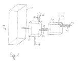
- FIG 1 is a section of a device 10 for generating / processing Fuel for a fuel cell (not shown) shown.
- the device 10 has generally the task of a hydrocarbon such as gasoline, methanol or the like in a fuel suitable for the fuel cell, for example Hydrogen to convert.
- the device 10 has a number of Reactor elements.
- One of these reactor elements is one Reformer 11, which is shown in detail in Figure 1.
- this requires that the Hydrocarbon is first converted into a vapor state. This happens at least with the help of a device for evaporation and overheating a medium as described in connection with Figures 2 to 11 becomes.
- FIG. This exists in the present Embodiment of two reaction stages, namely one as the first Reaction stage trained evaporator 20 and a second reaction stage trained superheater 50.
- An initially liquid medium is in the evaporator 20 first evaporated and then in the superheater 50 to the for Process mode in the reformer 11 required temperature set.
- both the evaporator 20 and the Superheater 50 is formed as a layer composite from individual layers.
- the structure of the Evaporator 20 will be explained in more detail below with reference to FIGS. 2 to 6 explained during the construction of the superheater 50 below with reference to the figures 7 to 11 is explained in more detail.
- the evaporator 20 receives water via a feed line 12 and a feed line 13 Fed gasoline.
- the water and gasoline are initially in the evaporator 20 mixed and then from the liquid to the gaseous state transferred, so evaporated.
- the evaporation takes place via a suitable one Heating means.
- This heating device becomes a heating medium passed through that its stored thermal energy to the one to be evaporated Water-petrol mixture transfers, so that it heats up and eventually evaporates becomes.
- hot exhaust gas is used as the heating medium Superheater used, which may still contain incompletely converted fuel gas and is fed via a line 15 from the superheater 50 into the evaporator 20.
- the superheater 50 has an overheating device which is in the form a catalytic burner is formed.
- the catalytic burner works based on a fuel gas mixture that in the present example There is hydrogen and combustion air. The hydrogen required for this will be fed into the superheater 50 via a line 17, while the combustion air reaches the superheater via a line 18.
- process air is still required for the operation of the reformer 11 advantageously before entering reformer 11 to a predetermined temperature is preheated.
- the process air can also be preheated in the superheater 50 take place so that it is connected to a feed line 19 for the process air.
- FIG. 4 shows the throughflow device 39 has a channel structure which is in turn formed from a number of channels 40 running parallel to one another.
- Both the evaporator 20 and the superheater 50 described later are formed in the present embodiment in microstructure technology, what means that the individual channels are designed as microchannels.
- the channels 40 of the throughflow device 39 consist of an inlet area 41, a reaction area 42 and an exit area 43 Entry area 41 and in exit area 43 a different channel structure than in Reaction area 42.
- the channels are one Inlet 44 connected to a medium to be evaporated.
- the channels 40 with a via the entry areas 41 Inlet 44 for the medium water connected via the feed line 12 ( Figure 1) provided.
- the outlet regions 43 of the channels 40 have an outlet 34 connected for the evaporated medium.
- the outlet 34 is in turn with the line 14 ( Figure 1) connected so that the evaporated medium after reaching the Outlet 34 can be introduced into the superheater 50 via the line 14.
- the evaporator 20 has a further layer on, which is designed as a mixing device 28.
- This mixing device 28 is in Figure 3 shown.
- the mixing device 28 also has a channel structure, wherein in the layer-like mixing device 28 a number of parallel to each other aligned channels 29 are provided.
- the channels 29 in turn have one Reaction area 31 and an exit area 34.
- the inlet 33 is in turn connected to the feed line 13 shown in FIG. 1 connected for the gasoline.
- the channels 29 are located in the mixing device 28 in the flow direction S. behind the barrier element 36.
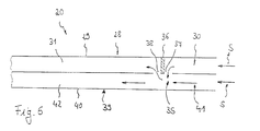
- FIG 6 the are in a schematic cross-sectional view Flow device 39 and the mixing device 28 are shown are arranged one above the other.
- the medium water flows in the flow direction S into the entry area 41 of the channel 40 from the throughflow device 39.
- the gasoline medium likewise flows into the channels 30 in the flow direction S Mixing device 28 a.
- the gasoline strikes the barrier element 36 and becomes down through the connection openings 37 into the channels 40 of the Flow device 39 pressed. In this area there is therefore a Mixing zone 35, in which the gasoline and water are mixed. Subsequently the gasoline-water mixture continues to flow through the channels 40 into them Reaction areas 42.
- the Barrier element 36 provided further connection openings 38 through which the Channels 40 are connected to the channels 29.
- the gasoline-water mixture also reaches in the channels 29 finally, a reaction area 31, the in the present example Reaction areas 42 and 31 of channels 40 and 29 lie one above the other. In the Reaction areas 42 and 31 now the actual evaporation of the gasoline-water mixture takes place.
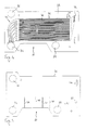
- At least one layer-shaped heating device 21 is provided, which in Figure 2 is shown.
- the heating device 21 also formed like a channel and has a number of parallel to each other aligned channels 22.
- the channels can in turn be made using microstructure technology be trained.
- channels 22 may be different Have channel cross-section than the channels 29, 30 and 40.
- the channels 22 have again via an inlet area 23, a reaction area 24 and a Exit area 25. Via the entry area 23, the channels have an inlet 26 connected for a heating medium.
- it is the Heating gas to fuel gas emerging from the superheater 50, so that the inlet 26 with the line 15 leaving the superheater 50 is connected.
- the heating medium flows through the channels 22 and leaves via the outlet areas 25 thereof Heating device 21 via an outlet 27 for the heating medium, which in present example is connected to the derivative 16 ( Figure 1).
- the evaporator 20 also works according to the counterflow principle, which means that the medium to be evaporated and the heating medium has an opposite flow direction. That the Heating medium flowing through the heating medium gives the stored therein Heat energy, this heat energy on the gasoline-water mixture to be heated is transmitted.
- the heating medium before the mixing zone 35 for the gasoline and water derived This eliminates the risk of pulsating boiling as well as one Pre-coking of the gasoline prevented. Because of the sandwich-like connection of the very good heat exchange between the individual layers Layers, the individual media, or that Mixture of media, but still to a sufficient extent via the heat conduction in the component preheat.
- the individual layers of the heating device 21, the throughflow device 39 and the mixing device 28 can advantageously be formed as thin metal foils the corresponding channels by an etching process or the like in the foils can be inserted.
- the individual layers can be in any Be stacked in a manner, preferably one mixing device 28 each or is arranged under a flow device 39, since this are connected to each other.
- a Flow device 39 is operated by two mixing devices 28.
- one flow device 39, or a combination of flow device 39 and Mixing device 28 is connected to a heating device 21.
- the number and design of the individual layers depends on the type of application and Requirement for the evaporator 20.
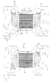
- Thermocouple layer 45 can be provided, as shown, for example, in FIG. 5 is shown.
- Thermocouple layer 45 can be a number of thermocouple channels 46, in which corresponding thermocouples 47 are arranged are. Depending on the number and design of the thermocouple channels 46 and Thermocouples 47 can measure the temperature in any range Evaporator 20 are measured.
- the superheater 50 again consists of a layer composite of a number of individual layers and is now explained in more detail in connection with FIGS. 7 to 11.
- the superheater 50 shown in FIGS. 7 to 11 has four basic components on.
- a first basic component relates to an overheating device.
- the The function of the overheating device is that which is necessary for the overheating Generate and provide thermal energy.
- the overheating device consists of two individual layers 51 and 62, which are shown in Figures 7 and 8.
- Another component of the Superheater 50 forms a throughflow device 68, which is shown in FIG. 9. What comes from the evaporator 20 flows through the throughflow device 68 vaporized gasoline-water mixture.
- Flow device 75 is provided, via which another medium, in In the present case, process air for the reformer 11 (FIG. 1) through the superheater 50 passed through and to the temperature required for the reforming process is preheated.
- the superheater 50 has at least one Thermocouple layer 81.
- the superheater of superheater 50 is here Embodiment designed as a catalytic burner.
- Both the single layer 51, as well as the individual layer 62 are formed and have a channel structure each have a number of channels 52 running parallel to one another and 63 respectively.
- the channels 52, 63 can as in the evaporator Microchannels can be formed.
- the catalytic burner works in such a way that the individual channels at least in regions with a catalyst material are coated. If an appropriate medium that works with the Catalyst material can react, flows through the coated channels, there is a corresponding reaction, which is usually exothermic, so that Heat energy is released. The heat energy released can then be used for Overheating of the other media can be used.
- the fuel gas which is the catalytically coated channels flows through, consisting of a hydrogen and combustion air Gas mixture.
- the hydrogen is introduced via the individual layer 51. To do this corresponding channels 53 are connected to a hydrogen inlet 56.
- the inlet 56 is in turn connected to the hydrogen feed line 17 (FIG. 1).
- the combustion air via a corresponding inlet 67 into the entry areas 64 of the channels 63 in the Single layer 62 initiated.
- the inlet 67 is connected to the combustion air supply line 18 ( Figure 1) connected.
- the fuel gas mixture is produced in a similar manner Way as in the production of the gasoline-water mixture in the evaporator, so that with regard to the basic mode of operation, also to the comments on the Figures 3, 4 and 6 referenced and hereby reference is made.
- the hydrogen-combustion air mixture then flows through the Reaction areas 65 of the channels 63 in the single layer 62 of the individual layer 51 behind the barrier 59 channels 52 are provided.
- the channels 52 are - as described for the evaporator 20 - via connection openings 61 with the Channels 63 connected so that two for the hydrogen-combustion air mixture superimposed flow passages are available, which is possible Pressure losses are positively influenced.
- Both the channels 63 and the channels 52 have reaction areas 65 or 54, which are coated with catalytic material. If so the hydrogen-combustion air mixture in the catalytically coated areas occurs, the exothermic reaction described above takes place. The free Heat energy can overheat the media to be overheated be used. The fuel gas will eventually be corresponding Outlet areas 55, 66 of the channels 52, 63 led to a heating medium outlet 57 and from this via the heating medium line 15 (FIG. 1) into the evaporator 20 passed where the heating medium continues to evaporate the water-gasoline mixture is used.
- the gasoline-water mixture evaporated in the evaporator 20 occurs via a medium inlet 74 into the throughflow device 68.
- the throughflow device 68 in turn has a channel structure and has a number of channels 69 aligned parallel to one another.
- the channels 69, the are again advantageously designed as microchannels are via their entry areas 70 connected to the medium inlet 74.
- the entry areas 70 are connected the reaction areas 71 in which the actual overheating takes place.
- the Outlet regions 72 are in the present exemplary embodiment as a mixing chamber 73 educated.
- the throughflow device 75 according to FIG. 10 is designed in a similar manner. Again, there are a number of channels aligned parallel to each other 76 are provided, which are preferably designed in the form of microchannels.
- the Channels 76 are connected to a medium inlet 80 in their entry region 77. In the present example 80 process air for the Reformers initiated the appropriate before entering the reformer Process temperature should be brought.
- the exit area 79 of the channels 76 is also designed as a mixing chamber 73. In this way it is achieved that the Process air and the vaporized gasoline-water mixture before entering the Reformer can be mixed within the superheater 50. In this way the reformer fed a homogeneously mixed mixture, the one uniform temperature.
- the superheater is compared to that Flow-through devices designed in such a way that the heating gas before the Process air entering inlet 80 is discharged via outlet 57 (Counterflow principle). Nevertheless, the overall heat conduction occurs Superheater 50 enables sufficient preheating of the process air. By this indirect preheating of the process air ensures that the process air no cooling effect on the gasoline / steam mixture entering via inlet 74 Has. An occurring cooling effect could lead to one as above lead to disadvantageous coking already described.
- the invention is not limited in number or arrangement of the individual layers of superheater 50 limited.
- the individual layers 51, 62 preferably in turn form a unit, since these are connected to one another via the connection openings 60, 61. there can either be provided that a single layer 62 with a Single layer 51 forms a unit. It is also conceivable that a single layer 62 is sandwiched between two individual layers 51 or vice versa.
- the arrangement and number of layers used depends on Area of application and performance requirements for superheater 50.
- thermocouple layer 81 can be provided, as exemplified in Figure 11 is shown.
- the thermocouple layer 81 in turn has Thermocouple channels 82 in which suitable thermocouples (not shown) are integrated.
- the setting and variation of the superheating temperatures can for example about the supply amount of hydrogen and combustion air and to be regulated by their ratio and / or total mass flow.
- At least one medium becomes a structurally simple and compact possibility created to vaporize individual media or media mixtures as well to overheat to temperatures required for further processes.
- An overheating is particularly advantageous if the following are to be carried out Process defined and possibly readjustable temperatures required are. Both can be realized with the device according to the invention.
- a Regulation of temperatures is possible in a particularly simple manner because this primarily results from the regulation of individual mass flows or from the percentage setting of individual components in Mixtures results.
Landscapes
- Engineering & Computer Science (AREA)
- General Engineering & Computer Science (AREA)
- Mechanical Engineering (AREA)
- Physics & Mathematics (AREA)
- Thermal Sciences (AREA)
- Chemical Kinetics & Catalysis (AREA)
- Chemical & Material Sciences (AREA)
- Life Sciences & Earth Sciences (AREA)
- Electrochemistry (AREA)
- General Chemical & Material Sciences (AREA)
- Sustainable Energy (AREA)
- Sustainable Development (AREA)
- Manufacturing & Machinery (AREA)
- Fuel Cell (AREA)
- Hydrogen, Water And Hydrids (AREA)
Abstract
Description
- Figur 1
- in schematischer Ansicht einen Ausschnitt aus einer Vorrichtung zum Erzeugen/Aufbereiten eines Brennstoffs für eine Brennstoffzelle mit einer erfindungsgemäßen Vorrichtung zum Verdampfen und Überhitzen wenigstens eines Mediums;
- Figuren 2 bis 5
- schematische Draufsichten auf verschiedene Einzelschichten eines erfindungsgemäßen Verdampfers;
- Figur 6
- eine schematische Querschnittsansicht eines Teils des erfindungsgemäßen Verdampfers; und
- Figuren 7 bis 11
- schematische Draufsichten auf verschiedene Einzelschichten eines erfindungsgemäßen Überhitzers.
- 10 =
- Vorrichtung zum Erzeugen/Aufbereiten von Brennstoff für eine Brennstoffzelle
- 11 =
- Reformer
- 12 =
- Zuleitung für Wasser
- 13 =
- Zuleitung für Benzin
- 14 =
- Leitung für verdampftes Medium
- 15 =
- Leitung für Heizmedium
- 16 =
- Ableitung für Heizmedium
- 17 =
- Leitung für Brennstoff
- 18 =
- Leitung für Verbrennungsluft
- 19 =
- Leitung für Prozeßluft
- 20 =
- Verdampfer
- 21 =
- Erhitzungseinrichtung/Schicht
- 22 =
- Kanal
- 23 =
- Eintrittsbereich
- 24 =
- Reaktionsbereich
- 25 =
- Austrittsbereich
- 26 =
- Einlaß Heizmedium
- 27 =
- Auslaß Heizmedium
- 28 =
- Mischeinrichtung/Schicht
- 29 =
- Kanal
- 30 =
- Kanal
- 31 =
- Reaktionsbereich
- 32 =
- Austrittsbereich
- 33 =
- Einlaß Medium (Benzin)
- 34 =
- Auslaß verdampftes Medium
- 35 =
- Mischzone
- 36 =
- Barriereelement
- 37 =
- Verbindungsöffnung
- 38 =
- Verbindungsöffnung
- 39 =
- Durchströmeinrichtung/Schicht
- 40 =
- Kanal
- 41 =
- Eintrittsbereich
- 42 =
- Reaktionsbereich
- 43 =
- Austrittsbereich
- 44 =
- Einlaß Medium (Wasser)
- 45 =
- Thermoelement-Schicht
- 46 =
- Thermoelement-Kanal
- 47 =
- Thermoelement
- 50 =
- Überhitzer
- 51 =
- Überhitzungseinrichtung/Schicht
- 52 =
- Kanal
- 53 =
- Kanal
- 54 =
- Reaktionsbereich
- 55 =
- Austrittsbereich
- 56 =
- Wasserstoff-Einlaß
- 57 =
- Heizmedium-Auslaß
- 58 =
- Mischzone
- 59 =
- Barriereelement
- 60 =
- Verbindungsöffnung
- 61 =
- Verbindungsöffnung
- 62 =
- Überhitzungseinrichtung/Schicht
- 63 =
- Kanal
- 64 =
- Eintrittsbereich
- 65 =
- Reaktionsbereich
- 66 =
- Austrittsbereich
- 67 =
- Verbrennungsluft-Einlaß
- 68 =
- Durchströmeinrichtung/Schicht
- 69 =
- Kanal
- 70 =
- Eintrittsbereich
- 71 =
- Reaktionsbereich
- 72 =
- Austrittsbereich
- 73 =
- Mischkammer
- 74 =
- Medium-Einlaß
- 75 =
- Durchströmeinrichtung/Schicht
- 76 =
- Kanal
- 77 =
- Eintrittsbereich
- 78 =
- Reaktionsbereich
- 79 =
- Austrittsbereich
- 80 =
- Medium-Einlaß
- 81 =
- Thermoelement-Schicht
- 82 =
- Thermoelement-Kanal
- S =
- Strömungsrichtung eines Mediums
Claims (23)
- Vorrichtung zum Verdampfen und Überhitzen wenigstens eines Mediums, mit wenigstens zwei Reaktionsstufen, wobei wenigstens eine erste Reaktionsstufe als Verdampfer (20) zum zumindest teilweisen Verdampfen des wenigstens einen Mediums ausgebildet ist, mit wenigstens einer Durchströmeinrichtung (39) zum Hindurchleiten des zu verdampfenden Mediums und mit wenigstens einer Erhitzungseinrichtung (21) zum Bereitstellen von Wärmeenergie zum zumindest teilweisen Verdampfen des die Durchströmeinrichtung (39) durchströmenden Mediums, wobei die Durchströmeinrichtung (39) mit der Erhitzungseinrichtung (21) thermisch gekoppelt ist, und wobei wenigstens eine, der wenigstens einen ersten Reaktionsstufe in Strömungsrichtung (S) des Mediums nachfolgende zweite Reaktionsstufe als Überhitzer (50) zum Überhitzen des verdampften Mediums oder zum vollständigen Verdampfen und Überhitzen des teilweise verdampften Mediums ausgebildet ist, mit wenigstens einer Durchströmeinrichtung (68) zum Hindurchleiten des aus dem Verdampfer (20) austretenden Mediums und mit wenigstens einer Überhitzungseinrichtung (51, 62) zum Bereitstellen von Wärmeenergie zum Überhitzen des die Durchströmeinrichtung (68) durchströmenden Mediums auf eine bestimmte Temperatur oder zum restlosen Verdampfen des Mediums und zum Überhitzen des Mediums auf eine bestimmte Temperatur, wobei die Durchströmeinrichtung (68) mit der Überhitzungseinrichtung (51, 62) thermisch gekoppelt ist,
dadurch gekennzeichnet, daß der wenigstens eine Verdampfer (20) und der wenigstens eine Überhitzer (50) als Schichtverbund aus Einzelschichten gebildet ist, daß die Durchströmeinrichtung (39) des Verdampfers (20) sowie die Durchströmeinrichtung (68) des Überhitzers (50) wenigstens eine Schicht mit Kanalstruktur mit wenigstens einem Kanal (40, 69) aufweist und daß zumindest eine Schicht der Durchströmeinrichtung (39) des Verdampfers (20) mit wenigstens einer schichtförmigen Erhitzungseinrichtung (21) und zumindest eine Schicht der Durchströmeinrichtung (68) des Überhitzers (50) mit wenigstens einer schichtförmigen Überhitzungseinrichtung (51, 62) verbunden ist. - Vorrichtung nach Anspruch 1, dadurch gekennzeichnet, daß der wenigstens eine Kanal (40, 69) jeder Durchströmeinrichtung (39, 68) einen Eintrittsbereich (41, 70), einen Reaktionsbereich (42, 71) sowie einen Austrittsbereich (43, 72) aufweist.
- Vorrichtung nach Anspruch 1 oder 2, dadurch gekennzeichnet, daß der Verdampfer (20) und/oder der Überhitzer (50) in Mikrostrukturtechnik ausgebildet ist/sind.
- Vorrichtung nach einem der Ansprüche 1 bis 3, dadurch gekennzeichnet, daß zumindest einzelne Schichten des Verdampfers (20) und/oder Überhitzers (50) als Folien ausgebildet sind.
- Vorrichtung nach einem der Ansprüche 1 bis 4, dadurch gekennzeichnet, daß die schichtförmige Erhitzungseinrichtung (21) des Verdampfers (20) wenigstens einen Kanal (22) zum Hindurchleiten eines Heizmediums aufweist.
- Vorrichtung nach Anspruch 5, dadurch gekennzeichnet, daß die Kanäle (22, 40) der Durchströmeinrichtung (39) und der Erhitzungseinrichtung (21) parallel zueinander ausgerichtet sind.
- Vorrichtung nach einem der Ansprüche 1 bis 6, dadurch gekennzeichnet, daß der Verdampfer (20) eine Mischeinrichtung (28) zum Hinzumischen wenigstens eines weiteren Mediums zum zu verdampfenden Medium aufweist.
- Vorrichtung nach Anspruch 7, soweit auf einen der Ansprüche 2 bis 6 rückbezogen, dadurch gekennzeichnet, daß die Mischeinrichtung (28) im Eintrittsbereich (41) des wenigstens einen Kanals (40) der Durchströmeinrichtung (39) des Verdampfers (20) vorgesehen ist.
- Vorrichtung nach Anspruch 7 oder 8, dadurch gekennzeichnet, daß die Mischeinrichtung (28) schichtförmig ausgebildet ist, daß die Mischeinrichtung (28) wenigstens eine Schicht mit wenigstens einem Kanal (30) aufweist, und daß der wenigstens eine Kanal (30) der Mischeinrichtung (28) in einer Mischzone (35) mit dem wenigstens einen Kanal (40) der Durchströmeinrichtung (39) des Verdampfers (20) verbunden ist.
- Vorrichtung nach Anspruch 9, dadurch gekennzeichnet, daß der wenigstens eine Kanal (30) der Mischeinrichtung (28) in Strömungsrichtung (S) des Mediums durch ein Barriereelement (36) begrenzt ist und daß der wenigstens eine Kanal (30) der Mischeinrichtung (28) mit dem Eintrittsbereich (41) des wenigstens einen Kanals (40) der Durchströmeinrichtung (39) des Verdampfers (20) verbunden ist.
- Vorrichtung nach einem der Ansprüche 2 bis 10, dadurch gekennzeichnet, daß die Erhitzungseinrichtung (21) zum Erhitzen des Mediums im Reaktionsbereich (42) des wenigstens einen Kanals (40) der Durchströmeinrichtung (39) des Verdampfers (20) ausgebildet ist.
- Vorrichtung nach Anspruch 11, dadurch gekennzeichnet, dass das die Erhitzungseinrichtung (21) durchströmende Heizmedium über einen Auslaß (27) in Bezug auf die Strömungsrichtung des Heizmediums zwischen dem Ende des Reaktionsbereichs (24) der Erhitzungseinrichtung (21) und der Mischzone (35) der Durchströmeinrichtung (39) abgeführt wird.
- Vorrichtung nach einem der Ansprüche 1 bis 12, dadurch gekennzeichnet, dass die Erhitzungseinrichtung (21) des Verdampfers (20) mit einem Heizmediumauslaß (57) aus dem Überhitzer (50) verbunden ist.
- Vorrichtung nach einem der Ansprüche 1 bis 13, dadurch gekennzeichnet, daß der Verdampfer (20) wenigstens ein Thermoelement (47) aufweist und daß das Thermoelement (47) vorzugsweise in einer Thermoelement-Schicht (45) angeordnet ist.
- Vorrichtung nach einem der Ansprüche 1 bis 14, dadurch gekennzeichnet, daß die schichtförmige Überhitzungseinrichtung (51, 62) des Überhitzers (50) wenigstens einen Kanal (53, 63) zum Hindurchleiten eines Überhitzungsmediums aufweist.
- Vorrichtung nach einem der Ansprüche 1 bis 15, dadurch gekennzeichnet, daß die Überhitzungseinrichtung (51, 62) als katalytischer Brenner ausgebildet ist.
- Vorrichtung nach Anspruch 15 oder 16, dadurch gekennzeichnet, daß die Überhitzungseinrichtung (50) aus wenigstens zwei Einzelschichten (51, 62) gebildet ist, daß jede Einzelschicht (51, 62) wenigstens einen Kanal (53, 63) aufweist, und daß die Kanäle (53, 63) der Einzelschichten (51, 62) in einer Mischzone (58) miteinander verbunden sind.
- Vorrichtung nach Anspruch 17, dadurch gekennzeichnet, daß der wenigstens eine Kanal (53) von einer der Einzelschichten (51) durch ein Barriereelement (59) begrenzt ist und daß der Kanal (53) mit einem Eintrittsbereich (64) des wenigstens einen Kanals (63) der anderen Einzelschicht (62) verbunden ist.
- Vorrichtung nach einem der Ansprüche 1 bis 18, dadurch gekennzeichnet, daß der Überhitzer (50) wenigstens eine schichtförmige Durchströmeinrichtung (75) für ein weiteres Medium aufweist, und daß die Durchströmeinrichtung (75) eine Kanalstruktur mit wenigstens einem Kanal (76) aufweist.
- Vorrichtung nach einem der Ansprüche 1 bis 19, dadurch gekennzeichnet, daß die Überhitzungseinrichtung (51, 62) zum Überhitzen des wenigstens einen Mediums im Reaktionsbereich (71, 78) des wenigstens einen Kanals (69, 76) der Durchströmeinrichtung (68, 75) ausgebildet ist.
- Vorrichtung nach Anspruch 20, dadurch gekennzeichnet, daß das die Überhitzungseinrichtung (51, 62) durchströmende Heizmedium über einen Auslaß (57) in Bezug auf die Strömungsrichtung des Heizmediums zwischen dem Ende des Reaktionsbereichs (54, 65) der Überhitzungseinrichtung (51, 62) und dem Einlaß (80) des wenigstens einen weiteren Mediums der Durchströmeinrichtung (en) (68, 75) abgeführt wird.
- Vorrichtung nach einem der Ansprüche 1 bis 21, dadurch gekennzeichnet, daß der Überhitzer (50) wenigstens ein Thermoelement aufweist und daß das Thermoelement vorzugsweise in einer Thermoelement-Schicht (81) angeordnet ist.
- Brennstoffzellensystem, mit wenigstens einer Brennstoffzelle und mit einer der Brennstoffzelle vorgeschalteten Vorrichtung (10) zum Erzeugen/Aufbereiten eines Brennstoffs,
dadurch gekennzeichnet, daß die Vorrichtung (10) zum Erzeugen/Aufbereiten des Brennstoffs wenigstens eine Vorrichtung zum Verdampfen und Überhitzen wenigstens eines Mediums nach einem der Ansprüche 1 bis 22 aufweist.
Applications Claiming Priority (2)
| Application Number | Priority Date | Filing Date | Title |
|---|---|---|---|
| DE10160834 | 2001-12-11 | ||
| DE10160834A DE10160834B4 (de) | 2001-12-11 | 2001-12-11 | Vorrichtung zum Verdampfen und Überhitzen wenigstens eines Mediums sowie Brennstoffzellensystem |
Publications (3)
| Publication Number | Publication Date |
|---|---|
| EP1319890A2 true EP1319890A2 (de) | 2003-06-18 |
| EP1319890A3 EP1319890A3 (de) | 2004-04-21 |
| EP1319890B1 EP1319890B1 (de) | 2008-10-01 |
Family
ID=7708805
Family Applications (1)
| Application Number | Title | Priority Date | Filing Date |
|---|---|---|---|
| EP02027418A Expired - Lifetime EP1319890B1 (de) | 2001-12-11 | 2002-12-09 | Vorrichtung zum Verdampfen und Überhitzen wenigstens eines Mediums sowie Brennstoffzellensystem |
Country Status (3)
| Country | Link |
|---|---|
| EP (1) | EP1319890B1 (de) |
| AT (1) | ATE409836T1 (de) |
| DE (2) | DE10160834B4 (de) |
Cited By (8)
| Publication number | Priority date | Publication date | Assignee | Title |
|---|---|---|---|---|
| WO2005056565A1 (de) * | 2003-12-11 | 2005-06-23 | Consortium für elektrochemische Industrie GmbH | Verfahren zur herstellung von isocyanatoorganosilanen unter verwendung von mikro strukturapparaten |
| EP1724514A1 (de) * | 2005-05-19 | 2006-11-22 | Black & Veatch Corporation | Verdampfer |
| WO2007009176A1 (en) | 2005-07-19 | 2007-01-25 | Ceramic Fuel Cells Limited | Steam generator |
| WO2014137867A1 (en) * | 2013-03-02 | 2014-09-12 | James Carl Loebig | Microchannel heat exchanger and methods of manufacture |
| AT521206A1 (de) * | 2018-05-03 | 2019-11-15 | Avl List Gmbh | Verdampfer für ein Brennstoffzellensystem sowie Brennstoffzellensystem |
| EP3909712A1 (de) * | 2020-05-15 | 2021-11-17 | L'air Liquide, Societe Anonyme Pour L'etude Et L'exploitation Des Procedes Georges Claude | Verfahren zur herstellung eines wärmetauschers, der eine temperatursonde umfasst |
| FR3110098A1 (fr) * | 2020-05-15 | 2021-11-19 | L'air Liquide, Société Anonyme Pour L’Étude Et L'exploitation Des Procédés Georges Claude | Procédé de fabrication d’un échangeur de chaleur comportant une sonde de température |
| EP4302041A4 (de) * | 2021-03-05 | 2025-02-19 | Copeland LP | Kunststofffolienwärmetauscher für niedrigdruck- und korrosive flüssigkeiten |
Families Citing this family (2)
| Publication number | Priority date | Publication date | Assignee | Title |
|---|---|---|---|---|
| DE102009039397A1 (de) * | 2009-08-31 | 2011-03-03 | Karlsruher Institut für Technologie | Mikrostrukturverdampfer |
| DE102017001567B4 (de) | 2017-02-20 | 2022-06-09 | Diehl Aerospace Gmbh | Verdampfer und Brennstoffzellenanordnung |
Citations (1)
| Publication number | Priority date | Publication date | Assignee | Title |
|---|---|---|---|---|
| DE2224826A1 (de) | 1971-05-20 | 1972-12-07 | Black, Sivalls & Bryson Inc., Kansas City, Mo. (V.StA.) | Verfahren zum Verdampfen und Überhitzen eines kryogenen Mediums |
Family Cites Families (5)
| Publication number | Priority date | Publication date | Assignee | Title |
|---|---|---|---|---|
| US5209906A (en) * | 1991-05-10 | 1993-05-11 | Her Majesty The Queen In Right Of Canada, As Represented By The Minister Of National Defence | Modular isothermal reactor |
| DE4426692C1 (de) * | 1994-07-28 | 1995-09-14 | Daimler Benz Ag | Zweistufige Verdampfereinheit für einen Reaktant-Massenstrom und Verfahren zur Herstellung desselben |
| JP3129670B2 (ja) * | 1997-02-28 | 2001-01-31 | 三菱電機株式会社 | 燃料改質装置 |
| DE10003273B4 (de) * | 2000-01-26 | 2005-07-21 | Ballard Power Systems Ag | Vorrichtung zum Verdampfen und/oder Überhitzen eines Mediums |
| DE10007764A1 (de) * | 2000-02-20 | 2001-08-23 | Gen Motors Corp | Brennerelement |
-
2001
- 2001-12-11 DE DE10160834A patent/DE10160834B4/de not_active Expired - Fee Related
-
2002
- 2002-12-09 EP EP02027418A patent/EP1319890B1/de not_active Expired - Lifetime
- 2002-12-09 DE DE50212831T patent/DE50212831D1/de not_active Expired - Lifetime
- 2002-12-09 AT AT02027418T patent/ATE409836T1/de not_active IP Right Cessation
Patent Citations (1)
| Publication number | Priority date | Publication date | Assignee | Title |
|---|---|---|---|---|
| DE2224826A1 (de) | 1971-05-20 | 1972-12-07 | Black, Sivalls & Bryson Inc., Kansas City, Mo. (V.StA.) | Verfahren zum Verdampfen und Überhitzen eines kryogenen Mediums |
Cited By (16)
| Publication number | Priority date | Publication date | Assignee | Title |
|---|---|---|---|---|
| WO2005056565A1 (de) * | 2003-12-11 | 2005-06-23 | Consortium für elektrochemische Industrie GmbH | Verfahren zur herstellung von isocyanatoorganosilanen unter verwendung von mikro strukturapparaten |
| EP1724514A1 (de) * | 2005-05-19 | 2006-11-22 | Black & Veatch Corporation | Verdampfer |
| WO2007009176A1 (en) | 2005-07-19 | 2007-01-25 | Ceramic Fuel Cells Limited | Steam generator |
| EP1904788A4 (de) * | 2005-07-19 | 2014-05-14 | Ceramic Fuel Cells Ltd | Dampferzeuger |
| US9109794B2 (en) | 2005-07-19 | 2015-08-18 | Ceramic Fuel Cells Limited | Steam generator |
| WO2014137867A1 (en) * | 2013-03-02 | 2014-09-12 | James Carl Loebig | Microchannel heat exchanger and methods of manufacture |
| CN112055906A (zh) * | 2018-05-03 | 2020-12-08 | Avl李斯特有限公司 | 用于燃料电池系统的蒸发器以及燃料电池系统 |
| WO2019210345A3 (de) * | 2018-05-03 | 2019-12-26 | Avl List Gmbh | Verdampfer für ein brennstoffzellensystem sowie brennstoffzellensystem |
| AT521206A1 (de) * | 2018-05-03 | 2019-11-15 | Avl List Gmbh | Verdampfer für ein Brennstoffzellensystem sowie Brennstoffzellensystem |
| AT521206B1 (de) * | 2018-05-03 | 2021-07-15 | Avl List Gmbh | Verdampfer für ein Brennstoffzellensystem sowie Brennstoffzellensystem |
| EP3909712A1 (de) * | 2020-05-15 | 2021-11-17 | L'air Liquide, Societe Anonyme Pour L'etude Et L'exploitation Des Procedes Georges Claude | Verfahren zur herstellung eines wärmetauschers, der eine temperatursonde umfasst |
| FR3110098A1 (fr) * | 2020-05-15 | 2021-11-19 | L'air Liquide, Société Anonyme Pour L’Étude Et L'exploitation Des Procédés Georges Claude | Procédé de fabrication d’un échangeur de chaleur comportant une sonde de température |
| FR3110099A1 (fr) * | 2020-05-15 | 2021-11-19 | L'air Liquide, Société Anonyme Pour L’Étude Et L'exploitation Des Procédés Georges Claude | Procédé de fabrication d’un échangeur de chaleur comportant une sonde de température |
| EP3912754A1 (de) * | 2020-05-15 | 2021-11-24 | L'Air Liquide Société Anonyme pour l'Etude et l'Exploitation des Procédés Georges Claude | Verfahren zur herstellung eines wärmetauschers, der eine temperatursonde umfasst |
| US11745280B2 (en) | 2020-05-15 | 2023-09-05 | L'Air Liquide, Société Anonyme pour l'Etude et l'Exploitation des Procédés Georges Claude | Method for manufacturing a heat exchanger having a temperature probe |
| EP4302041A4 (de) * | 2021-03-05 | 2025-02-19 | Copeland LP | Kunststofffolienwärmetauscher für niedrigdruck- und korrosive flüssigkeiten |
Also Published As
| Publication number | Publication date |
|---|---|
| DE10160834B4 (de) | 2007-03-15 |
| DE10160834A1 (de) | 2003-06-26 |
| EP1319890A3 (de) | 2004-04-21 |
| EP1319890B1 (de) | 2008-10-01 |
| ATE409836T1 (de) | 2008-10-15 |
| DE50212831D1 (de) | 2008-11-13 |
Similar Documents
| Publication | Publication Date | Title |
|---|---|---|
| DE19720294C1 (de) | Reformierungsreaktor und Betriebsverfahren hierfür | |
| DE69806658T2 (de) | Vorrichtung für die Reformierung von Kraftstoffen | |
| DE19754013C2 (de) | Vorrichtung und Verfahren zur Wasserdampfreformierung eines Kohlenwasserstoffs | |
| DE19639150C2 (de) | Zentrale Heizvorrichtung für ein Gaserzeugungssystem | |
| DE60128159T2 (de) | Vorrichtung zur reformierung von Brennstoff | |
| DE60216875T2 (de) | Verfahren und Vorrichtung zum Verdampfen von Brennstoff für Reformer eines Brennstoffzellensystems | |
| DE112004001696T5 (de) | Verdampfer und Verfahren zum Verdampfen | |
| DE10132370B4 (de) | Vorrichtung und Verfahren zum Verdampfen flüssiger Medien | |
| AT521064B1 (de) | Stapelartig aufgebautes Brennstoffzellensystem | |
| EP1250719B1 (de) | Verdampfer in mikrostrukturtechnik sowie brennstoffzellensystem | |
| EP1319890B1 (de) | Vorrichtung zum Verdampfen und Überhitzen wenigstens eines Mediums sowie Brennstoffzellensystem | |
| DE10136970A1 (de) | Vorrichtung zur Erzeugung von wasserstoffhaltigem Gas für eine Brennstoffzellenanlage | |
| DE10110465A1 (de) | Reaktor | |
| EP1261993A2 (de) | Vorrichtung und verfahren zum erhitzen und/oder verdampfen flüssiger oder gasförmiger medien | |
| EP1224967A2 (de) | Reaktor | |
| DE10046692C2 (de) | Vorrichtung zur Verdampfung einer Flüssigkeit | |
| DE112005001542T5 (de) | Wärmetauscher | |
| AT520976B1 (de) | Wärmetauscher für ein Brennstoffzellensystem und Verfahren zum Betreiben eines Brennstoffzellensystems | |
| DE102006031480B4 (de) | Flacher Mikroreformer | |
| EP1383599A2 (de) | Vorrichtung zum erzeugen und/oder aufbereiten eines brennstoffs für eine brennstoffzelle | |
| EP1304310A2 (de) | Verfahren und Vorrichtung zur Reformierung flüssiger Kohlenwasserstoffgemische | |
| EP1090878A1 (de) | Dampfreformierungsanlage | |
| DE19717067C2 (de) | Reformierungsreaktoranlage, insbesondere zur Wasserdampfreformierung von Methanol | |
| DE10222804C1 (de) | Gaserzeugungssystem zum Erzeugen von nahezu reinem Wasserstoff und Verfahren zum Starten eines solchen Gaserzeugungssytems | |
| WO2001065194A1 (de) | Vorrichtung zum verdampfen flüssiger medien |
Legal Events
| Date | Code | Title | Description |
|---|---|---|---|
| PUAI | Public reference made under article 153(3) epc to a published international application that has entered the european phase |
Free format text: ORIGINAL CODE: 0009012 |
|
| AK | Designated contracting states |
Designated state(s): AT BE BG CH CY CZ DE DK EE ES FI FR GB GR IE IT LI LU MC NL PT SE SI SK TR |
|
| AX | Request for extension of the european patent |
Extension state: AL LT LV MK RO SI |
|
| PUAL | Search report despatched |
Free format text: ORIGINAL CODE: 0009013 |
|
| AK | Designated contracting states |
Kind code of ref document: A3 Designated state(s): AT BE BG CH CY CZ DE DK EE ES FI FR GB GR IE IT LI LU MC NL PT SE SI SK TR |
|
| AX | Request for extension of the european patent |
Extension state: AL LT LV MK RO SI |
|
| 17P | Request for examination filed |
Effective date: 20040826 |
|
| AKX | Designation fees paid |
Designated state(s): AT BE BG CH CY CZ DE DK EE ES FI FR GB GR IE IT LI LU MC NL PT SE SI SK TR |
|
| 17Q | First examination report despatched |
Effective date: 20060404 |
|
| GRAP | Despatch of communication of intention to grant a patent |
Free format text: ORIGINAL CODE: EPIDOSNIGR1 |
|
| GRAS | Grant fee paid |
Free format text: ORIGINAL CODE: EPIDOSNIGR3 |
|
| GRAA | (expected) grant |
Free format text: ORIGINAL CODE: 0009210 |
|
| AK | Designated contracting states |
Kind code of ref document: B1 Designated state(s): AT BE BG CH CY CZ DE DK EE ES FI FR GB GR IE IT LI LU MC NL PT SE SI SK TR |
|
| REG | Reference to a national code |
Ref country code: GB Ref legal event code: FG4D Free format text: NOT ENGLISH |
|
| REG | Reference to a national code |
Ref country code: CH Ref legal event code: EP |
|
| RAP2 | Party data changed (patent owner data changed or rights of a patent transferred) |
Owner name: P21-POWER FOR THE 21ST CENTURY GMBH |
|
| REG | Reference to a national code |
Ref country code: IE Ref legal event code: FG4D Free format text: LANGUAGE OF EP DOCUMENT: GERMAN |
|
| REF | Corresponds to: |
Ref document number: 50212831 Country of ref document: DE Date of ref document: 20081113 Kind code of ref document: P |
|
| NLT2 | Nl: modifications (of names), taken from the european patent patent bulletin |
Owner name: P21-POWER FOR THE 21ST CENTURY GMBH Effective date: 20081029 |
|
| PG25 | Lapsed in a contracting state [announced via postgrant information from national office to epo] |
Ref country code: SI Free format text: LAPSE BECAUSE OF FAILURE TO SUBMIT A TRANSLATION OF THE DESCRIPTION OR TO PAY THE FEE WITHIN THE PRESCRIBED TIME-LIMIT Effective date: 20081001 |
|
| NLV1 | Nl: lapsed or annulled due to failure to fulfill the requirements of art. 29p and 29m of the patents act | ||
| REG | Reference to a national code |
Ref country code: IE Ref legal event code: FD4D |
|
| PG25 | Lapsed in a contracting state [announced via postgrant information from national office to epo] |
Ref country code: BG Free format text: LAPSE BECAUSE OF FAILURE TO SUBMIT A TRANSLATION OF THE DESCRIPTION OR TO PAY THE FEE WITHIN THE PRESCRIBED TIME-LIMIT Effective date: 20090101 Ref country code: ES Free format text: LAPSE BECAUSE OF FAILURE TO SUBMIT A TRANSLATION OF THE DESCRIPTION OR TO PAY THE FEE WITHIN THE PRESCRIBED TIME-LIMIT Effective date: 20090112 |
|
| PG25 | Lapsed in a contracting state [announced via postgrant information from national office to epo] |
Ref country code: NL Free format text: LAPSE BECAUSE OF FAILURE TO SUBMIT A TRANSLATION OF THE DESCRIPTION OR TO PAY THE FEE WITHIN THE PRESCRIBED TIME-LIMIT Effective date: 20081001 Ref country code: FI Free format text: LAPSE BECAUSE OF FAILURE TO SUBMIT A TRANSLATION OF THE DESCRIPTION OR TO PAY THE FEE WITHIN THE PRESCRIBED TIME-LIMIT Effective date: 20081001 Ref country code: PT Free format text: LAPSE BECAUSE OF FAILURE TO SUBMIT A TRANSLATION OF THE DESCRIPTION OR TO PAY THE FEE WITHIN THE PRESCRIBED TIME-LIMIT Effective date: 20090302 |
|
| BERE | Be: lapsed |
Owner name: P21-POWER FOR THE 21ST CENTURY G.M.B.H. Effective date: 20081231 |
|
| PG25 | Lapsed in a contracting state [announced via postgrant information from national office to epo] |
Ref country code: MC Free format text: LAPSE BECAUSE OF NON-PAYMENT OF DUE FEES Effective date: 20081231 Ref country code: DK Free format text: LAPSE BECAUSE OF FAILURE TO SUBMIT A TRANSLATION OF THE DESCRIPTION OR TO PAY THE FEE WITHIN THE PRESCRIBED TIME-LIMIT Effective date: 20081001 Ref country code: IE Free format text: LAPSE BECAUSE OF FAILURE TO SUBMIT A TRANSLATION OF THE DESCRIPTION OR TO PAY THE FEE WITHIN THE PRESCRIBED TIME-LIMIT Effective date: 20081001 Ref country code: EE Free format text: LAPSE BECAUSE OF FAILURE TO SUBMIT A TRANSLATION OF THE DESCRIPTION OR TO PAY THE FEE WITHIN THE PRESCRIBED TIME-LIMIT Effective date: 20081001 |
|
| REG | Reference to a national code |
Ref country code: CH Ref legal event code: PL |
|
| PLBE | No opposition filed within time limit |
Free format text: ORIGINAL CODE: 0009261 |
|
| STAA | Information on the status of an ep patent application or granted ep patent |
Free format text: STATUS: NO OPPOSITION FILED WITHIN TIME LIMIT |
|
| PG25 | Lapsed in a contracting state [announced via postgrant information from national office to epo] |
Ref country code: CZ Free format text: LAPSE BECAUSE OF FAILURE TO SUBMIT A TRANSLATION OF THE DESCRIPTION OR TO PAY THE FEE WITHIN THE PRESCRIBED TIME-LIMIT Effective date: 20081001 Ref country code: IT Free format text: LAPSE BECAUSE OF FAILURE TO SUBMIT A TRANSLATION OF THE DESCRIPTION OR TO PAY THE FEE WITHIN THE PRESCRIBED TIME-LIMIT Effective date: 20081001 Ref country code: SE Free format text: LAPSE BECAUSE OF FAILURE TO SUBMIT A TRANSLATION OF THE DESCRIPTION OR TO PAY THE FEE WITHIN THE PRESCRIBED TIME-LIMIT Effective date: 20090101 |
|
| 26N | No opposition filed |
Effective date: 20090702 |
|
| PG25 | Lapsed in a contracting state [announced via postgrant information from national office to epo] |
Ref country code: SK Free format text: LAPSE BECAUSE OF FAILURE TO SUBMIT A TRANSLATION OF THE DESCRIPTION OR TO PAY THE FEE WITHIN THE PRESCRIBED TIME-LIMIT Effective date: 20081001 Ref country code: BE Free format text: LAPSE BECAUSE OF NON-PAYMENT OF DUE FEES Effective date: 20081231 |
|
| PG25 | Lapsed in a contracting state [announced via postgrant information from national office to epo] |
Ref country code: LI Free format text: LAPSE BECAUSE OF NON-PAYMENT OF DUE FEES Effective date: 20081231 Ref country code: CH Free format text: LAPSE BECAUSE OF NON-PAYMENT OF DUE FEES Effective date: 20081231 |
|
| PG25 | Lapsed in a contracting state [announced via postgrant information from national office to epo] |
Ref country code: FR Free format text: LAPSE BECAUSE OF NON-PAYMENT OF DUE FEES Effective date: 20091231 |
|
| PG25 | Lapsed in a contracting state [announced via postgrant information from national office to epo] |
Ref country code: AT Free format text: LAPSE BECAUSE OF NON-PAYMENT OF DUE FEES Effective date: 20081209 |
|
| PG25 | Lapsed in a contracting state [announced via postgrant information from national office to epo] |
Ref country code: LU Free format text: LAPSE BECAUSE OF NON-PAYMENT OF DUE FEES Effective date: 20081209 Ref country code: CY Free format text: LAPSE BECAUSE OF FAILURE TO SUBMIT A TRANSLATION OF THE DESCRIPTION OR TO PAY THE FEE WITHIN THE PRESCRIBED TIME-LIMIT Effective date: 20081001 |
|
| PG25 | Lapsed in a contracting state [announced via postgrant information from national office to epo] |
Ref country code: TR Free format text: LAPSE BECAUSE OF FAILURE TO SUBMIT A TRANSLATION OF THE DESCRIPTION OR TO PAY THE FEE WITHIN THE PRESCRIBED TIME-LIMIT Effective date: 20081001 |
|
| PG25 | Lapsed in a contracting state [announced via postgrant information from national office to epo] |
Ref country code: GR Free format text: LAPSE BECAUSE OF FAILURE TO SUBMIT A TRANSLATION OF THE DESCRIPTION OR TO PAY THE FEE WITHIN THE PRESCRIBED TIME-LIMIT Effective date: 20090102 |
|
| PGFP | Annual fee paid to national office [announced via postgrant information from national office to epo] |
Ref country code: DE Payment date: 20110112 Year of fee payment: 9 Ref country code: FR Payment date: 20110128 Year of fee payment: 9 |
|
| PGFP | Annual fee paid to national office [announced via postgrant information from national office to epo] |
Ref country code: GB Payment date: 20110120 Year of fee payment: 9 |
|
| GBPC | Gb: european patent ceased through non-payment of renewal fee |
Effective date: 20111209 |
|
| REG | Reference to a national code |
Ref country code: FR Ref legal event code: ST Effective date: 20120831 |
|
| REG | Reference to a national code |
Ref country code: DE Ref legal event code: R119 Ref document number: 50212831 Country of ref document: DE Effective date: 20120703 |
|
| PG25 | Lapsed in a contracting state [announced via postgrant information from national office to epo] |
Ref country code: DE Free format text: LAPSE BECAUSE OF NON-PAYMENT OF DUE FEES Effective date: 20120703 Ref country code: GB Free format text: LAPSE BECAUSE OF NON-PAYMENT OF DUE FEES Effective date: 20111209 |
|
| PG25 | Lapsed in a contracting state [announced via postgrant information from national office to epo] |
Ref country code: FR Free format text: LAPSE BECAUSE OF NON-PAYMENT OF DUE FEES Effective date: 20120102 |