EP1319762A1 - Cab for construction machinery - Google Patents
Cab for construction machinery Download PDFInfo
- Publication number
- EP1319762A1 EP1319762A1 EP01965628A EP01965628A EP1319762A1 EP 1319762 A1 EP1319762 A1 EP 1319762A1 EP 01965628 A EP01965628 A EP 01965628A EP 01965628 A EP01965628 A EP 01965628A EP 1319762 A1 EP1319762 A1 EP 1319762A1
- Authority
- EP
- European Patent Office
- Prior art keywords
- pillars
- pillar
- mount
- cab
- base
- Prior art date
- Legal status (The legal status is an assumption and is not a legal conclusion. Google has not performed a legal analysis and makes no representation as to the accuracy of the status listed.)
- Granted
Links
Images






Classifications
-
- B—PERFORMING OPERATIONS; TRANSPORTING
- B66—HOISTING; LIFTING; HAULING
- B66C—CRANES; LOAD-ENGAGING ELEMENTS OR DEVICES FOR CRANES, CAPSTANS, WINCHES, OR TACKLES
- B66C13/00—Other constructional features or details
- B66C13/52—Details of compartments for driving engines or motors or of operator's stands or cabins
- B66C13/54—Operator's stands or cabins
-
- B—PERFORMING OPERATIONS; TRANSPORTING
- B62—LAND VEHICLES FOR TRAVELLING OTHERWISE THAN ON RAILS
- B62D—MOTOR VEHICLES; TRAILERS
- B62D27/00—Connections between superstructure or understructure sub-units
- B62D27/02—Connections between superstructure or understructure sub-units rigid
- B62D27/023—Assembly of structural joints
-
- B—PERFORMING OPERATIONS; TRANSPORTING
- B62—LAND VEHICLES FOR TRAVELLING OTHERWISE THAN ON RAILS
- B62D—MOTOR VEHICLES; TRAILERS
- B62D33/00—Superstructures for load-carrying vehicles
- B62D33/06—Drivers' cabs
-
- E—FIXED CONSTRUCTIONS
- E02—HYDRAULIC ENGINEERING; FOUNDATIONS; SOIL SHIFTING
- E02F—DREDGING; SOIL-SHIFTING
- E02F9/00—Component parts of dredgers or soil-shifting machines, not restricted to one of the kinds covered by groups E02F3/00 - E02F7/00
- E02F9/16—Cabins, platforms, or the like, for drivers
- E02F9/163—Structures to protect drivers, e.g. cabins, doors for cabins; Falling object protection structure [FOPS]; Roll over protection structure [ROPS]
Definitions
- This invention relates to a cab for construction machines, which can be suitably applied, for example, to hydraulic excavators, hydraulic cranes and the like.
- construction machines such as hydraulic excavators, for example, are largely constituted by a lower structure, an upper structure which is rotatably mounted on the lower structure, and a working mechanism which is provided on a front portion of the upper structure for lifting loads up and down.
- a cab is provided on a revolving frame of the upper structure as an operating room to be occupied by an operator at the control of the machine.
- the cabs of hydraulic excavators of this sort are usually formed in a box-like shape, from a standpoint of protecting operators.
- a box-like cab construction including mount bases located at four corners and each provided with an upward fitting joint projection, base link frames connecting the four mount bases in transverse and longitudinal directions, right and left front pillars erected on right front and left front mount bases, right and left rear pillars erected on right rear and left rear mount bases, right and left roof pillars connecting upper end portions of the front and rear pillars, a front tie frame connecting upper end portions of right and left front pillars, and a rear tie frame connecting upper end portions of right and left rear pillars (e.g., as disclosed in Japanese Laid-Open Patent Publication No. 2000-198469).
- the prior art cab is built up firstly by fitting lower ends of left and right front pillars on the fitting joint projection of the mount bases, and welding fitted lower ends of the respective pillars to the mount bases to erect them thereon.
- front and rear pillars are erected on mount bases by fitting lower ends of the respective pillars on joint projections which are provided on the side of the mount bases and forming a weld around the circumference of distal end portions which are abutted on the respective mount bases.
- a cab for a construction machine which is so arranged to facilitate positioning of left and right front pillars as well as left and right rear pillars on the respective mount bases and at the same time to increase the strength of their joint portions.
- a cab for construction machines including mount bases located at four corners and each provided with an upward fitting joint projection; base link frames arranged to connect the mount bases in transverse and longitudinal directions of a machine; left and right front pillars erected on left and right front mount bases; left and right rear pillars erected on left and right rear mount bases; left and right roof pillars arranged to longitudinally connect upper end portions of the front and rear pillars; a front tie frame arranged to transversely connect upper end portions of the left and right front pillars; and a rear tie frame arranged to transversely connect upper end portions of the left and right rear pillars.
- the cab according to the present invention as defined in claim 1 comprises: a notched portion provided in a lower end portion of each one of the front and rear pillars for fitting engagement with the fitting joint projection of the mount base; a lower end portion of each one of the front and rear pillars being fitted on the fitting joint projection of the mount base and securely fixed to the latter by a weld formed along and between marginal edge portions around the notched portion and the fitting joint projection.
- the respective front and rear pillars can be readily and correctly set in position on the respective mount bases by engagement with the fitting joint projections.
- a weld can be formed along and between marginal edge portions around the notched portions and the fitting joint projections in such a way as to prolong the welding distance and away from a distal or root end portion of the pillar where concentration of stress occurs.
- the notched portion in each one of the front and rear pillars is in the form of an opening of an inverted U-shape corresponding to profile of the fitting joint projection on the side of the mount base.
- a pillar which is set in position on a mount base, with its notched portion in engagement with a fitting joint projection on the side of the mount base, can be securely welded to the latter by forming a weld over a longer distance along and between marginal edge portions around the notched portion and the fitting joint projection.
- the mount bases are each constituted by a base plate to be fixed on the side of a vehicle body, and a fitting joint projection rising upward from the base plate in such a way as to plug the notched portion.
- FIG. 1 a lower structure of the hydraulic excavator, and at 2 an upper structure which is rotatably mounted on the lower structure 1.
- a front working mechanism 3 is provided on a front portion of the upper structure 2 for lifting a front attachment up and down, for example, for an excavating operation.
- the upper structure 2 is largely constituted by a revolving frame 4, a cab 11 which is mounted on a left front portion of the revolving frame 4, which will be described hereinafter, an outer shield cover 5 which is provided on the revolving frame 4 and on the right and rear sides of the cab 11 as shown in Figs. 2 and 3, a counterweight 6 which is attached to the rear end of the revolving frame 4, and an engine 7 which is mounted transversely on the revolving frame 4 at a position on the rear side of the cab 11.
- the cab which is mounted on a left front portion of the revolving frame 4 to provide an operating room to be occupied by an operator at the control of the machine.
- the cab 11 is internally provided with an operator' s seat along with various operating and control levers (none of which is shown).
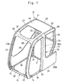
- the cab 11 is largely constituted by a cab frame 12, front window 38, door 39, rear panel 41, side panel 43, roof panel 44, front window glass 45, rear window glass 46, left side window glass 47 and right side window glass 48, which will be described in greater detail hereinafter.
- the cab frame 12 which forms a bone structure of the cab 11.
- the cab frame 12 is constituted by a base frame 13, front pillars 22 and 23, rear pillars 24 and 25, roof pillars 26 and 27, front joint members 28 and 29, rear joint members 30 and 31, front tie frame 32, rear tie frame 33 and center pillar 35, which will be described after.
- component parts including the front pillars, rear pillars, roof pillars, front joint members and rear joint members, only the component parts on the right side are shown in the drawings, and the component parts on the left side are indicated by a reference numeral in brackets.
- the base frame of the cab 11 is in the form of a rectangular frame structure which is constituted by left and right front mount bases 14 and 15, left and right rear mount bases 16 and 17, left and right base link frames 18 and 19, and front and rear base link frames 20 and 21, which will be described hereinafter.
- Designated at 14 is the left front mount base which is located at a left front corner of the base frame 13, and at 15 is the right front mount base which is located at a right front corner of the base frame 13.
- the left front mount base 14 and the right front mount base 15 are in the form of castings which are formed by casting steel material in a mold.
- the front mount bases 14 and 15 are constituted by base plates 14A and 15A substantially of triangular shape, and fitting joint projections 14B and 15B which is cast integrally with and projected upward from the base plates 14A and 15A.
- bolt holes 14C and 15C are bored through the base plates 14A and 15A, respectively. Bolts (not shown) are passed through these bolt holes 14C and 15C at the time of fixing the mount bases 14 and 15 to anti-vibrational mounts (not shown) which support the cab 11 on the revolving frame 4.
- the fitting joint projections 14B and 15B are constituted by: upstanding plate portions 14B1 and 15B1 of a substantially rectangular shape rising upward from the respective base plates 14A and 15A and facing laterally outward; ridge portions 14B2 and 15B2 projecting laterally outward from outer faces of the upstanding plate portions 14B1 and 15B1 toward notched portions 22B and 23B in the front pillars 22 and 23, which will be described in greater detail hereinafter; and triangular reinforcing ribs 14B3 and 15B3 which are fitted between the inner side of the upstanding plate portions 14B1 and 15B1 and the base plates 14A and 15A, respectively.
- the fitting joint projections 14B and 15B need to be fitted in lower end portions of the front pillars 22 and 23. Therefore, the fitting joint projections 14B and 15B are inclined in the forward direction in conformity with the shape of the lower ends of the front pillars 22 and 23, and the ridge portions 14B2 and 15B2 are projected laterally on the outer side.
- the fitting joint projections 14B and 15B are fitted in lower end portions of the front pillars 22 and 23, the notched portions 22B and 23B in the front pillars 22 and 23 are closed by the upstanding plate portions 14B1 and 15B1 of the fitting joint projections 14B and 15B, respectively. Further, at this time, the ridge portions 14B2 and 15B2 fit in the notched portions 22B and 23B, respectively. Thus, a weld of a longer distance can be formed when welding the upstanding plate portions 14B1 and 15B1 and the ridge portions 14B2 and 15B2 to the notched portions 22B and 23B of the front pillars 22 and 23.
- the front pillars 22 and 23 can be fixed to the mount bases 14 and 15 through a stronger weld.
- the reinforcing ribs 14B3 and 15B3 serve to enhance the strength of the mount bases 14 and 15 against falling of the upstanding plate portions 14B1 and 15B1, ridge portions 14B2 and 15B2 and front pillars 22 and 23.
- a left rear mount base and a right rear mount base which are located at a left rear corner and a right rear corner of the base frame 13, respectively.
- the left and right rear mount bases 16 and 17 are castings of steel material.
- the rear mount bases 16 and 17 are provided with base plates 16A and 17A of substantially triangular shape and fitting joint projections 16B and 17B which are projected upward from the base plates 16A and 17A.
- the base plates 16A and 17A and the fitting joint projections 16B and 17B are cast integrally together, respectively.
- bolt holes 16C and 17C are bored through the base plates 16A and 17A, respectively, and bolts (both not shown) are passed through the bolt holes 16C and 17C at the time of fixing the mount bases 16 and 17 to anti-vibrational mounts on the side of the revolving frame 4.
- the fitting joint projections 16B and 17B are formed substantially in a semi-circular shape in section and projected straight upward to fit in notched portions 24A and 25A in lower end portions of rear pillars 24 and 25, which will be described hereinafter.
- Indicated at 18 is a left base link frame which is connected between the base plate 14A of the left front mount base 14 and the base plate 16A of the left rear mount base 16.
- Indicated at 19 is a right base link frame which is connected between the base plate 15A of the right front mount base 15 and the base plate 17A of the right rear mount base 17.
- Indicated at 20 is a front base link frame which is connected between the base plate 14A of the left front mount base 14 and the base plate 15A of the right front mount base 15.
- Indicated at 21 is rear base link frame which is connected between the base plate 16A of the left rear mount base 16 and the base plate 17A of the right rear mount base 17.
- These base link frames 18 to 21 are each constituted by an angle bar which is formed by folding a plate into L-shape.
- the left and right front pillars 22 and 23 are each constituted by a steel pipe of a diversified sectional shape which is formed by drawing an ordinary round steel pipe, and bent to present a forwardly convex profile. Further, for guiding a front window 38 which will be described after, the front pillars 22 and 23 are integrally formed with a roller groove 22A or 23A on one side which comes to a transversely inner side of the front pillars 22 and 23 in an assembled state.
- notched portions 22B and 23B are formed in lower end portions of the front pillars 22 and 23 for fitting engagement with the fitting joint projections 14B and 15B of the front mount bases 14 and 15, respectively.
- the notched portion 22B is formed in a lateral surface at the right side of the left front pillar 22, while the notched portion 23B is formed in a lateral surface at the left side of the right front pillar 23 in face to face relation with the notched portion 22B.
- the notched portions 22B and 23B are each formed in an inverted U-shape, which is open at the lower end.
- the notched portions 22B and 23B are in the form of openings of a substantially rectangular shape, which fit on the ridge portions 14B2 and 15B2 and which are closed by the upstanding plate portions 14B1 and 15B1 of the front mount bases 14 and 15, respectively, when fitted on the latter.
- the lower end of the right front pillar 23 is fitted on the fitting joint projection 15B of the right front mount base 15, in such a way that the notched portion 23B is closed by the fitting joint projection 15B, and in this state the two parts are securely fixed to each other by welding.
- a weld is formed not only around the distal end of the right front pillar 23 which is abutted on the base plate 15A of the right front mount base 15, but also along and between marginal edge portions around the notched portion 23B and the fitting joint projection 15B of the right front mount base 15 (i.e., the upstanding plate portion 15B1 and the ridge portion 15B2), which are in fitting engagement with each other.
- This welded joint construction makes it possible to prevent concentration of stress in certain localities and to increase the distance of weld and as a result to increase the strength of welded portions.
- Indicated at 24 and 25 are a left rear pillar and a right rear pillar which are located in the left and right rear corners of the base frame 13, respectively.
- the left and right rear pillars 24 and 25 are each constituted by a steel pipe of a diversified shape which is formed by drawing an ordinary round steel pipe.
- notched portions 24A and 25A which fit on the protrusive fitting joint projections 16B and 17B of the rear mount bases 16 and 17.
- the notched portion 24A is formed in a lateral surface at the right side of the left rear pillar 24, while the notched portion 25A is formed in a lateral surface at the left side of the right rear pillar 25 in face to face relation with the notched portion 24A.
- the notched portions 24A and 25A are each formed in an inverted U-shape, which is open at the lower end.
- the notched portions 24A and 25A are in the form of openings of a substantially rectangular shape, which fit on the fitting joint projections 16B and 17B and which are closed by the fitting joint projections 16B and 17B of the rear mount bases 16 and 17, respectively, when fitted on the latter.
- the notched portion 25A of the right rear pillar 25 is fitted on the fitting joint projection 17B of the right rear mount base 17 and, in this state, securely fixed to the latter by welding.
- a weld is formed not only around the distal end of the right rear pillar 25 which is abutted on the base plate 17A of the right rear mount base 17, but also along and between marginal edge portions around the notched portion 25A and the fitting joint projection 17B of the right rear mount base 17, which are in fitting engagement with each other.
- This welded joint construction makes it possible to prevent concentration of stress in certain localities and to increase the distance of the weld and as a result to increase the strength of welded portions.
- a left roof pillar which is extended between upper end portions of the left front pillar 22 and the left rear pillar 24, and at 27 is a right roof pillar which is extended between upper end portions of the right front pillar 23 and the right rear pillar 25.
- the left and right roof pillars 26 and 27 are moderately curved in an upwardly convex shape. Further, on a transversely inner side, the left and right roof pillars 26 and 27 are integrally formed with roller grooves 26A and 27A, respectively.
- each one of the left and right roof pillars 26 and 27 is constituted by a steel pipe of a diversified sectional shape, which is formed into a curved shape by a bending operation.
- a fore end portion of the left roof pillar 26 is connected to an upper end portion of the left front pillar 22 through a left front joint member 28, which will be described hereinafter, while a rear end portion of the left roof pillar 26 is connected to an upper end portion of the left rear pillar 24 through a left rear joint member 30, which will also be described hereinafter.
- a fore end portion of the right roof pillar 27 is connected to an upper end portion of the right front pillar 23 through a right front joint member 29, which will be described hereinafter, while a rear end portion of the right roof pillar 27 is connected to an upper end portion of the right rear pillar 25 through a right rear joint member 31, which will also be described hereinafter.
- left front joint member 28 which is provided between the left front pillar 22 and the left roof pillar 26
- right front joint member which is provided between the right front pillar 23 and the right roof pillar 27.
- the left and right front joint members 28 and 29 are each in the form of a square pipe of an arcuately curved shape.
- the left front joint member 28 is formed with a roller groove 28A longitudinally on an inner lateral side continuously to and from the roller grooves 22A on the left front pillar 22 and the roller groove 26A on the left roof pillar 26.
- the right front joint member 29 is formed with a roller groove 29A longitudinally on an inner lateral side continuously to and from the roller groove 23A on the right front pillar 23 and the roller groove 27A on the right roof pillar 27.
- one end of the left front joint member 28 is fitted in an upper end portion of the left front pillar 22 and securely fixed to the latter by welding, while the other end is fitted in a fore end portion of the left roof pillar 26 and securely fixed to the latter by welding. Consequently, the left front pillar 22 and the left roof pillar 26 are connected to each other through the left front joint member 28.
- one end of the right front joint member 29 is fitted in an upper end portion of the right front pillar 23 and securely fixed to the latter by welding, while the other end is fitted in a fore end portion of the right roof pillar 27 and securely fixed to the latter by welding.
- the right front pillar 23 and the right roof pillar 27 are connected to each other through the right front joint member 29.
- left rear joint member 30 which is provided between the left rear pillar 24 and the left roof pillar 26
- at 31 is a right rear joint member which is provided between the right rear pillar 25 and the right roof pillar 27.
- the left and right rear joint members 30 and 31 are each formed in a hollow box-like shape.
- a front side of the left rear joint member 30 is fitted in a rear end portion of the left roof pillar 26 and securely fixed to the latter by welding, while a lower side of the left rear joint member 30 is fitted in an upper end portion of the left rear pillar 24 and securely fixed to the latter by welding. Consequently, the left rear pillar 24 and the left roof pillar 26 are connected to each other through the left rear joint member 30.
- a front side of the right rear joint member 31 is fitted in a rear end portion of the right roof pillar 27 and securely fixed to the latter by welding, while a lower side of the right rear joint member 31 is fitted in an upper end portion of the right rear pillar 25 and securely fixed to the latter by welding.
- the right rear pillar 25 and the right roof pillar 27 are connected to each other through the right rear joint member 31.
- a front tie frame (see Fig. 7) which is provided in upper portion at the front end of the cab frame 12.
- the front tie frame 32 is constituted by a transversely extending elongated plate member. Joint portions at the opposite ends of the front tie frame 32 are securely fixed to the left and right front joint members 28 and 29 by welding. Thus, upper end portions of the front pillars 22 and 23 are transversely connected to each other by the front tie frame 32 through the respective front joint members 28 and 29.
- the rear tie frame 33 is a rear tie frame which is provided in an upper portion at the rear end of the cab frame 12.
- the rear tie frame 33 is constituted by a transversely extending elongated square pipe or tube. Joint portions at the opposite ends of the rear tie frame 33 are securely fixed to the left and right rear joint members 30 and 31 by welding.
- upper end portions of the respective rear pillars 24 and 25 are transversely connected to each other by the rear tie frame 33 through the rear joint members 30 and 31.
- intermediate rear tie frame which is provided at the rear end of the cab frame 12, at a spaced position and on the lower side of the rear tie frame 33.
- the intermediate rear tie frame 34 is constituted by a transversely extending plate which is folded into a rod-like shape. Opposite ends of the intermediate rear tie frame 34 are securely fixed to vertically intermediate portions of the left and right rear pillars 24 and 25 by welding. Thus, at vertically intermediate portions, the respective rear pillars 24 and 25 are transversely connected to each other by the intermediate rear tie frame 34.
- the center pillar 35 is in the form of a hollow structure, fabricated by welding together inner and outer panels 36 and 37 which are pressed substantially into a L-shape in section.
- the center pillar 35 is composed of a vertically extending pillar section 35A, and a side panel section 35B which is extended rearward from a lower portion of the vertical pillar section 35A.
- the center pillar 35 which is arranged in the above-described manner, is located in an intermediate position between the front and rear ends of the cab frame.
- Lower end portions of the pillar section 35A and the side panel section 35B are securely fixed to the left base link frame 18 of the base frame 13 by welding, while an upper end portion of the pillar section 35A is securely fixed to the left roof pillar 26 by welding.
- the front window 38 is movable along the roller grooves 23A on the two front pillars 22 and 23, the roller grooves 27A on the two roof pillars 26 and 27 and the roller grooves 29A on the two front joint members 28 and 29.
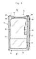
- the front window 38 is normally held in a closed position between the left and right front pillars 22 and 23 as shown in Fig. 6, but it can be lifted into an open position between the left and right roof pillars 26 and 27, namely, into an open position under the roof panel 44 which will be described hereinafter.
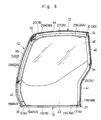
- Indicated at 39 is a door which is fitted between the center pillar 35 and the left front pillar 22. As shown in Fig. 4, the door 39 is pivotally connected to the center pillar 35 at its rear side by means of hinges 40 as a swing door.
- Indicated at 41 is a rear panel which is formed of a metal sheet, and the rear panel 41 is fitted between the left and right rear pillars 24 and 25 in such a way as to shield the rear side of the cab frame 12.
- Designated at 42 is a corner panel which is similarly formed of a metal sheet, and the corner panel 42 is fitted on the left rear pillar 24 in such a way as to cover the latter.
- Indicated at 43 is a side panel which is formed of a metal sheet, and the side panel 43 is securely fixed to the right base link frame 19, right front pillar 23 and right rear pillar 25 in such a way as to shield the right side of the cab frame 12.
- Indicated at 44 is a roof panel which is formed of a metal sheet, and the roof panel is securely fixed to the left and right roof pillars 26 and 27, the front tie frame 32 and the rear tie frame 33.
- denoted at 45 is a pane of lower front window glass which is fitted between front base link frame 20 and the left and right front pillars 22 and 23 under the front window 38.
- Indicated at 46 is a pane of rear window glass which is fitted between the left and right rear pillars 24 and 25 and between the rear tie frame 33 and the rear panel 41.
- Indicated at 47 is a pane of left side window glass which is fitted in position between the center pillar 35 and the corner panel 42.
- indicated at 48 is a pane of right side window glass which is fitted in position between the right front pillar 23 and the right rear pillar 25.
- the hydraulic excavator according to the present invention is operated in the manner as follows.
- a vehicle drive lever is turned by an operator in the cab 11 to drive the lower structure 1 in the forward or reverse direction.
- control levers are turned to operate the front working mechanism 3 and to rotate the upper structure 2.
- the front pillars 22 and 23 are firstly attached to the front mount bases 14 and 15 and other component parts are assembled, for example, in the order and in the manner as described below.
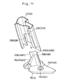
- the front pillars 22 and 23 are attached to the front mount bases 14 and 15 by fitting the notched portions 22B and 23B on the fitting joint projections 14B and 15B as indicated by an arrow in Fig. 11.
- the front pillars 22 and 23 can be readily set in correct positions relative to the front mount bases 14 and 15, respectively.
- marginal edge portions around the notched portions 22B and 23B are also welded to the fitting joint projections 14B and 15B, respectively. Therefore, it becomes possible to form a weld or welds avoiding those portions where concentration of stress is likely to occur, and to increase the distance of weld for the purpose of enhancing the strength of the welded joint portions to a sufficient degree.
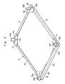
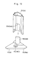
- the two rear pillars 24 and 25 are attached to the rear mount bases 16 and 17 by fitting the notched portions 24A and 25A on the fitting joint projections 16B and 17B of the rear mount bases 16 and 17, respectively, as indicated by an arrow in Fig. 13.
- the rear pillars 24 and 25 can be readily set in correct positions relative to the rear mount bases 16 and 17.
- the strength of the welded joint portions can be enhanced in the same way as the welding of the front pillars 22 and 23 and the front mount bases 14 and 15 described above.
- the roof pillars 26 and 27 are attached to the upper ends of the front pillars 22 and 23 and the rear pillars 24 and 25 through the front joint members 28 and 29 and the rear joint members 30 and 31. Then, the front joint members 28 and 29 and the rear joint members 30 and 31 are transversely connected to each other by the front tie frame 32 and the rear tie frame 33, respectively. Further, the center pillar 35 is attached to the left base link frame 18 of the base frame 13 and the left roof pillar 26 to finish the assembling of the cab frame 12.
- the front window 38, door 39, rear panel 41, corner panel 42, side panel 43, roof panel 44, low front window glass 45, rear window glass 46, left side window glass 47 and right side window glass 48 are successively fitted in or on the cab frame 12 to assemble the cab 11.
- the fitting joint projections 14B to 17B of the mount bases 14 to 17 are cast integrally with the respective base plates 14A to 17A, the pillars 22 to 25 can be set in position on the mount bases 14 to 17 simply by fitting them on the fitting joint projections 14B to 17B, respectively.
- the fitting joint projections 14B to 17B serve to position the pillars 22 to 25 correctly and readily on the base frame 13, and thus contribute to improve the efficiency of assembling work, not to mention the productivity of the cab.
- the pillars 22 to 25 which are provided with the notched portions 22B, 23B, 24A and 25A respectively in their lower end portions can be securely fixed to the mount bases 14 to 17 by welding, with the notched portions 22B, 23B, 24A and 25A in fitting engagement with the fitting joint projections 14B to 17B on the side of the mount bases 14 to 17. Therefore, in welding lower ends of the pillars 22 to 25, a weld can also be formed along marginal edge portions around the notched portions 22B, 23B, 24A and 25A which are in abutting engagement with the fitting joint projections 14B to 17B, respectively.
- the above arrangements permit to form a weld or welds avoiding distal or root end portions of the pillars where concentration of stress will occur, and to increase the welding distance along marginal edge portions around the notched portions 22B, 23B, 24A and 25A to improve the strength of welded joint portions and reliability of the machine.
- mount bases 14 to 17 are provided with bolt holes 14C to 17C, respectively, these mount bases 14 to 17 can be fixed on anti-vibrational mounts which are provided on the revolving frame 4 to support the cab 11 thereon, by means of bolts which are passed through the respective bolt holes 14C to 17C.
- the structures of the front mount bases 14 and 15 as well as the rear mount bases 16 and 17 are castings of steel material, the fitting joint projections 14B to 17B can be cast integrally with the base plates 14A to 17A of the mount bases 14 to 17, respectively, and therefore the whole mount bases including the fitting joint projections can be fabricated at a low cost.
- left and right front pillars 22, 23 as well as the rear pillars 24 and 25 are each constituted by a steel pipe of a diversified sectional shape which is formed by drawing an ordinary round steel pipe, so that they can also be fabricated easily at a low cost.
- the base frame 13 is assembled in the first place by connecting the mount bases 14 to 17 with the base link frames 18 to 21, and then the front pillars 22 and 23 and the rear pillars 24 and 25 are successively attached to the base frame 13.
- the present invention is not limited to the particular example given.
- the cab 11 may be assembled as in the case of a modification shown in Fig. 14.
- a left section of the cab 11 is assembled by the use of the component parts on the left side including the mount bases 14 and 16, base link frame 18, front pillar 22, rear pillar 24, roof pillar 26 and center pillar 35, separately from a right section of the cab 11 which is similarly assembled by the use of the component parts on the right side including mount bases 15 and 17, base link frame 19, front pillar 23, rear pillar 25 and roof pillar 27.
- the resulting two assemblies are connected with each other by means of the base link frames 20 and 21, front tie frame 32, rear tie frames 33 and 34, rear panel 41 and roof panel 44.
- structures of the front mount bases 14 and 15 as well as the structures of the rear mount bases 16 and 17 are formed by casting steel material in a mold.
- the present invention is not limited to cast mount bases.
- the respective mount bases 14 to 17 may be formed by forging or machining if desired.
- the construction machine cab 11 of the present invention has been described as a cab of a hydraulic excavator.
- the present invention is not limited to the particular example shown.
- the present invention can be similarly applied to hydraulic cranes or other construction machines.
- each one of front and rear pillars is provided with a notched portion in a lower end portion for fitting engagement with a fitting joint projection on the side of a mount base, and securely fixed to the mount base by forming a weld along and between marginal edge portions around the notched portion and the fitting joint projection which are in abutting engagement with each other.
- each one of the front and rear pillars can be readily and correctly set in position on the mount base.
- This contributes to improve the efficiency of assembling work and to enhance the productivity.
- a weld can be formed along and between marginal edge portions around the notched portion and the fitting joint projection which is in abutting engagement with the notched portion. Therefore, in welding a pillar to a mount base, it becomes possible to prolong the welding distance and to avoid distal end portions of the pillar where concentration of stress is likely to occur.
- the strength of the welded joint portion can be enhanced to a marked degree.
Landscapes
- Engineering & Computer Science (AREA)
- Mechanical Engineering (AREA)
- Chemical & Material Sciences (AREA)
- Combustion & Propulsion (AREA)
- Transportation (AREA)
- Mining & Mineral Resources (AREA)
- Civil Engineering (AREA)
- General Engineering & Computer Science (AREA)
- Structural Engineering (AREA)
- Body Structure For Vehicles (AREA)
Abstract
Description
Claims (3)
- A cab for construction machines, including mount bases located at four corners and each provided with an upward fitting joint projection, base link frames arranged to connect said mount bases in transverse and longitudinal directions of a machine; left and right front pillars erected on left and right front mount bases; left and right rear pillars erected on left and right rear mount bases; left and right roof pillars arranged to longitudinally connect upper end portions of said front and rear pillars; a front tie frame arranged to transversely connect upper end portions of said left and right front pillars; and a rear tie frame arranged to transversely connect upper end portions of said left and right rear pillars; characterized in that said cab comprises:a notched portion provided in a lower end portion of each one of said front and rear pillars for fitting engagement with said fitting joint projection of said mount base;a lower end portion of each one of said front and rear pillars being fitted on said fitting joint projection of said mount base and securely fixed to the latter by a weld formed along and between marginal edge portions around said notched portion and said fitting joint projection.
- A cab for construction machines as defined in claim 1, wherein said notched portion in each one of said front and rear pillars is in the form of an opening of an inverted U-shape corresponding to profile of said fitting joint projection.
- A cab for construction machines as defined in claim 1 or 2, wherein said mount bases are each constituted by a base plate to be fixed on the side of a vehicle body, and a fitting joint projection rising upward from said base plate in such a way as to plug said notched portion.
Applications Claiming Priority (3)
| Application Number | Priority Date | Filing Date | Title |
|---|---|---|---|
| JP2000282394 | 2000-09-18 | ||
| JP2000282394 | 2000-09-18 | ||
| PCT/JP2001/007963 WO2002022967A1 (en) | 2000-09-18 | 2001-09-13 | Cab for construction machinery |
Publications (3)
| Publication Number | Publication Date |
|---|---|
| EP1319762A1 true EP1319762A1 (en) | 2003-06-18 |
| EP1319762A4 EP1319762A4 (en) | 2006-08-02 |
| EP1319762B1 EP1319762B1 (en) | 2007-08-22 |
Family
ID=18766925
Family Applications (1)
| Application Number | Title | Priority Date | Filing Date |
|---|---|---|---|
| EP01965628A Expired - Lifetime EP1319762B1 (en) | 2000-09-18 | 2001-09-13 | Cab for construction machinery |
Country Status (7)
| Country | Link |
|---|---|
| US (1) | US6582010B2 (en) |
| EP (1) | EP1319762B1 (en) |
| KR (1) | KR100418073B1 (en) |
| CN (1) | CN1140675C (en) |
| AU (1) | AU759661B2 (en) |
| DE (1) | DE60130128T2 (en) |
| WO (1) | WO2002022967A1 (en) |
Cited By (1)
| Publication number | Priority date | Publication date | Assignee | Title |
|---|---|---|---|---|
| EP2907928A1 (en) * | 2014-02-17 | 2015-08-19 | Kobelco Construction Machinery Co., Ltd. | Floor member and working machine |
Families Citing this family (42)
| Publication number | Priority date | Publication date | Assignee | Title |
|---|---|---|---|---|
| US6568746B2 (en) * | 2000-09-18 | 2003-05-27 | Hitachi Construction Machinery Co., Ltd. | Cab for construction machinery |
| KR20040019843A (en) * | 2002-08-30 | 2004-03-06 | 가부시키가이샤 고마쓰 세이사쿠쇼 | Cabin structure for work vehicle |
| US6947819B2 (en) * | 2002-11-13 | 2005-09-20 | Caterpillar Inc | Swivel joint for a work machine |
| DE602004021565D1 (en) | 2003-02-27 | 2009-07-30 | Komatsu Mfg Co Ltd | ROPS-COVER FOR HYDRAULIC TRAILER |
| US7140670B2 (en) * | 2003-08-19 | 2006-11-28 | Custom Products Of Litchfield | Interconnection system for overhead frame structures |
| EP1666343B1 (en) * | 2003-09-09 | 2009-07-15 | Komatsu Ltd. | Cab of construction machinery |
| JP4673009B2 (en) * | 2004-06-21 | 2011-04-20 | 日立建機株式会社 | Construction machinery cab |
| US7290829B2 (en) * | 2004-06-29 | 2007-11-06 | Kubota Corporation | Working vehicle with a cab |
| GB2418892A (en) * | 2004-10-06 | 2006-04-12 | Cnh Belgium Nv | Cab for an agricultural vehicle |
| CN101223077B (en) * | 2005-07-19 | 2010-05-26 | 株式会社小松制作所 | Construction machinery cab structure |
| KR100689293B1 (en) * | 2005-07-25 | 2007-03-02 | 볼보 컨스트럭션 이키프먼트 홀딩 스웨덴 에이비 | Upper frame structure supporting the cab of the construction machine |
| JP2007106286A (en) * | 2005-10-14 | 2007-04-26 | Kobelco Contstruction Machinery Ltd | Cab of working machine |
| US7744148B2 (en) * | 2005-12-23 | 2010-06-29 | Caterpillar Sarl | Rotatable cab with toe guard |
| US20070145780A1 (en) * | 2005-12-23 | 2007-06-28 | Caterpillar Inc. | Rotatable cab with multi-piece deck |
| US7677646B2 (en) * | 2006-03-13 | 2010-03-16 | Kubota Corporation | Vehicle frame for work vehicle and method for manufacturing same |
| US7607722B2 (en) * | 2006-08-28 | 2009-10-27 | Deere & Company | Roll-over protective structure for a work vehicle with removable portion for air transport |
| USD549245S1 (en) * | 2006-09-22 | 2007-08-21 | Saf-T-Cab, Inc. | Off highway mobile equipment cab |
| US8434795B2 (en) * | 2007-08-02 | 2013-05-07 | Saf-T-Cab, Inc. | Dual door release handle |
| KR101307286B1 (en) * | 2008-07-16 | 2013-09-11 | 가부시키가이샤 고마쓰 세이사쿠쇼 | Cab for construction machine |
| JP5088268B2 (en) * | 2008-08-11 | 2012-12-05 | コベルコ建機株式会社 | Cab and mobile construction machine equipped with the same |
| US8579363B2 (en) * | 2008-12-16 | 2013-11-12 | Daniel E. Davis | Rollover protection cab |
| DE102010015163A1 (en) * | 2010-04-16 | 2011-10-20 | Liebherr-Hydraulikbagger Gmbh | Construction machine or transhipment device |
| JP5706110B2 (en) * | 2010-07-29 | 2015-04-22 | プレス工業株式会社 | Cab frame structure of construction machinery |
| CN103180518B (en) * | 2010-10-20 | 2015-11-25 | 沃尔沃建造设备有限公司 | Construction machine cab with rollover protective structure |
| CA137849S (en) * | 2010-11-08 | 2011-06-07 | Lakeport Metalcraft And Welding | Safety bar |
| US8950553B2 (en) | 2010-12-29 | 2015-02-10 | Lakeport Metalcraft And Welding | Safety bar |
| JP5567516B2 (en) * | 2011-03-15 | 2014-08-06 | 住友建機株式会社 | Construction machinery |
| CN102730087A (en) * | 2011-04-07 | 2012-10-17 | 苏州益高电动车辆制造有限公司 | Cab frame |
| JP2012219516A (en) * | 2011-04-08 | 2012-11-12 | Hitachi Constr Mach Co Ltd | Cab for construction machine |
| USD734915S1 (en) * | 2011-05-06 | 2015-07-21 | Lakeport Metalcraft And Welding | Safety bar |
| CN102180409A (en) * | 2011-05-31 | 2011-09-14 | 济南诚毅弘远工贸有限公司 | Plug-in operating room |
| US8833832B2 (en) * | 2011-08-16 | 2014-09-16 | Ford Global Technologies, Llc | Node for connecting vehicle body portions |
| US8439432B2 (en) * | 2011-09-19 | 2013-05-14 | Ford Global Technologies, Llc | Roof structure for a vehicle with no center pillar |
| JP5654508B2 (en) * | 2012-03-07 | 2015-01-14 | 株式会社小松製作所 | Construction machine cab frame and coating method thereof |
| JP5881637B2 (en) | 2013-03-29 | 2016-03-09 | 株式会社クボタ | Cabin equipment for work equipment |
| ITMO20130161A1 (en) * | 2013-06-04 | 2014-12-05 | Cnh Italia Spa | CABIN FOR A VEHICLE. |
| USD743449S1 (en) * | 2013-07-24 | 2015-11-17 | Yanmar Co., Ltd. | Tractor |
| JP5991350B2 (en) * | 2014-08-01 | 2016-09-14 | コベルコ建機株式会社 | Construction machinery cab |
| USD785504S1 (en) * | 2016-05-05 | 2017-05-02 | Fab Fours Inc. | Windshield protector |
| CN106741179B (en) * | 2016-12-22 | 2023-07-28 | 江苏萝卜交通科技有限公司 | Frame for electric vehicle |
| JP7195805B2 (en) * | 2018-07-31 | 2022-12-26 | 株式会社小松製作所 | working machine |
| JP7213762B2 (en) * | 2019-06-19 | 2023-01-27 | 株式会社小松製作所 | cabs and work vehicles |
Family Cites Families (26)
| Publication number | Priority date | Publication date | Assignee | Title |
|---|---|---|---|---|
| US4023851A (en) * | 1974-02-19 | 1977-05-17 | Caterpillar Tractor Co. | Modular operator's compartment for tractors |
| JPS57107961A (en) * | 1980-12-26 | 1982-07-05 | Iseki & Co Ltd | Rear frame in cabin or the like |
| DE3346986A1 (en) * | 1983-12-24 | 1985-07-18 | Fleck, Andreas, 2000 Hamburg | CAR BOX |
| JPS60154962A (en) * | 1984-01-20 | 1985-08-14 | Iseki & Co Ltd | Safety-frame installation apparatus for tractor |
| BE900391A (en) * | 1984-08-17 | 1984-12-17 | Tachikawa Spring Co | VEHICLE CAB. |
| NZ213234A (en) * | 1984-11-26 | 1987-09-30 | Kubota Ltd | Front screen for tractor cabin |
| US4695342A (en) * | 1985-03-28 | 1987-09-22 | General Motors Corporation | Method of forming truck cab frames |
| JPS6311487A (en) * | 1986-06-30 | 1988-01-18 | Kubota Ltd | Frame structure for traveling vehicle |
| JPS63162381A (en) * | 1986-12-25 | 1988-07-05 | Kubota Ltd | Tractor cabin |
| JPH03287475A (en) * | 1990-04-04 | 1991-12-18 | Yanmar Diesel Engine Co Ltd | Cabin support mechanism for tractor |
| JP3287475B2 (en) | 1991-12-27 | 2002-06-04 | 日本ペイント株式会社 | Curable resin composition |
| US5273340A (en) * | 1992-10-19 | 1993-12-28 | Caterpillar Inc. | Cab assembly |
| JP2872934B2 (en) * | 1995-03-23 | 1999-03-24 | 日立建機株式会社 | Driver's cab |
| JPH09109922A (en) * | 1995-10-13 | 1997-04-28 | Hitachi Constr Mach Co Ltd | Working machine with cab |
| US5820199A (en) * | 1995-11-08 | 1998-10-13 | Caterpillar Inc. | Frame assembly for an operator's compartment |
| US6065799A (en) * | 1997-10-09 | 2000-05-23 | Komatsu Est Corporation | Cabin-installation structure for construction machine |
| JP3474417B2 (en) | 1997-12-04 | 2003-12-08 | 日立建機株式会社 | Operator's cab of construction machinery |
| JP2000198469A (en) * | 1998-10-31 | 2000-07-18 | Press Kogyo Co Ltd | Cab for construction machinery using cast joints |
| US6189954B1 (en) * | 1998-12-02 | 2001-02-20 | Martin Sheet Metal, Inc. | Cab enclosure panels |
| US6149228A (en) * | 1998-12-09 | 2000-11-21 | Deere & Company | Modular operator enclosure |
| JP2000234352A (en) | 1999-02-12 | 2000-08-29 | Hitachi Constr Mach Co Ltd | Cab for construction machinery |
| US6206446B1 (en) * | 1999-03-15 | 2001-03-27 | Jerry K. Slayden | ATV all-weather cab |
| JP2001115491A (en) * | 1999-10-20 | 2001-04-24 | Hitachi Constr Mach Co Ltd | Cab for construction machinery |
| JP2001180519A (en) * | 1999-12-28 | 2001-07-03 | Kawasaki Heavy Ind Ltd | Work vehicles |
| US6568746B2 (en) * | 2000-09-18 | 2003-05-27 | Hitachi Construction Machinery Co., Ltd. | Cab for construction machinery |
| JP2002172979A (en) * | 2000-12-08 | 2002-06-18 | Komatsu Ltd | Vehicle console box mounting structure |
-
2001
- 2001-09-13 AU AU86231/01A patent/AU759661B2/en not_active Ceased
- 2001-09-13 KR KR10-2002-7005751A patent/KR100418073B1/en not_active Expired - Fee Related
- 2001-09-13 WO PCT/JP2001/007963 patent/WO2002022967A1/en not_active Ceased
- 2001-09-13 CN CNB018025242A patent/CN1140675C/en not_active Expired - Lifetime
- 2001-09-13 EP EP01965628A patent/EP1319762B1/en not_active Expired - Lifetime
- 2001-09-13 DE DE60130128T patent/DE60130128T2/en not_active Expired - Lifetime
- 2001-09-13 US US10/111,598 patent/US6582010B2/en not_active Expired - Lifetime
Cited By (1)
| Publication number | Priority date | Publication date | Assignee | Title |
|---|---|---|---|---|
| EP2907928A1 (en) * | 2014-02-17 | 2015-08-19 | Kobelco Construction Machinery Co., Ltd. | Floor member and working machine |
Also Published As
| Publication number | Publication date |
|---|---|
| AU759661B2 (en) | 2003-04-17 |
| WO2002022967A1 (en) | 2002-03-21 |
| EP1319762A4 (en) | 2006-08-02 |
| DE60130128D1 (en) | 2007-10-04 |
| US6582010B2 (en) | 2003-06-24 |
| AU8623101A (en) | 2002-03-26 |
| DE60130128T2 (en) | 2008-05-15 |
| KR100418073B1 (en) | 2004-02-14 |
| US20020153748A1 (en) | 2002-10-24 |
| CN1140675C (en) | 2004-03-03 |
| CN1388845A (en) | 2003-01-01 |
| EP1319762B1 (en) | 2007-08-22 |
| KR20020053075A (en) | 2002-07-04 |
Similar Documents
| Publication | Publication Date | Title |
|---|---|---|
| EP1319762B1 (en) | Cab for construction machinery | |
| EP1325988B1 (en) | Cab for construction machinery | |
| JP3747733B2 (en) | Construction machine cab | |
| JP4686565B2 (en) | Superstructure of work equipment | |
| KR101002227B1 (en) | Cap structure of construction machinery | |
| EP1666343A2 (en) | Cab of construction machinery | |
| JP4814235B2 (en) | Construction machinery cab structure | |
| WO2010007870A1 (en) | Cab for construction machine | |
| CN100447352C (en) | Cab for construction machinery | |
| JP4274402B2 (en) | Construction machinery cab | |
| JP2007216957A (en) | Cab for construction machinery | |
| JP4327658B2 (en) | Construction machinery cab | |
| JPH07150589A (en) | Work machine | |
| JP4029632B2 (en) | Cabin structure of construction machinery | |
| JP5065968B2 (en) | Column support member and construction machine cab | |
| JP2005330700A (en) | Construction machinery cab | |
| JP2002088812A (en) | Cab for construction machinery | |
| JP2024031361A (en) | construction machinery cabin | |
| JPH1037244A (en) | Construction machine swivel frame | |
| JP2024031360A (en) | construction machinery cabin | |
| JP4266892B2 (en) | End structure of work link and end structure of boom | |
| JP5112149B2 (en) | Column support structure and construction machine cab | |
| JP2003336285A (en) | Revolving superstructure frame of construction equipment | |
| JP2010254086A (en) | Cab in construction machinery | |
| JP2009234439A (en) | Cab of construction machine |
Legal Events
| Date | Code | Title | Description |
|---|---|---|---|
| PUAI | Public reference made under article 153(3) epc to a published international application that has entered the european phase |
Free format text: ORIGINAL CODE: 0009012 |
|
| 17P | Request for examination filed |
Effective date: 20020606 |
|
| AK | Designated contracting states |
Designated state(s): AT BE CH CY DE DK ES FI FR GB GR IE IT LI LU MC NL PT SE TR |
|
| RIN1 | Information on inventor provided before grant (corrected) |
Inventor name: SAKYO, TSUYOSHI Inventor name: SATOU, KATSUHIRO,ROOM 302 Inventor name: KOMATSU, KAZUNORI,ROOM C-1107, CITYNA KANDATSU |
|
| RBV | Designated contracting states (corrected) |
Designated state(s): AT BE CH CY DE DK FR GB IT LI NL SE |
|
| A4 | Supplementary search report drawn up and despatched |
Effective date: 20060703 |
|
| 17Q | First examination report despatched |
Effective date: 20060831 |
|
| GRAP | Despatch of communication of intention to grant a patent |
Free format text: ORIGINAL CODE: EPIDOSNIGR1 |
|
| RBV | Designated contracting states (corrected) |
Designated state(s): DE FR GB IT NL SE |
|
| GRAS | Grant fee paid |
Free format text: ORIGINAL CODE: EPIDOSNIGR3 |
|
| GRAA | (expected) grant |
Free format text: ORIGINAL CODE: 0009210 |
|
| AK | Designated contracting states |
Kind code of ref document: B1 Designated state(s): DE FR GB IT NL SE |
|
| REG | Reference to a national code |
Ref country code: GB Ref legal event code: FG4D |
|
| RIN1 | Information on inventor provided before grant (corrected) |
Inventor name: SAKYO, TSUYOSHI Inventor name: KOMATSU, KAZUNORI,ROOM C-1107, CITYNA KANDATSU Inventor name: SATOU, KATSUHIRO |
|
| REF | Corresponds to: |
Ref document number: 60130128 Country of ref document: DE Date of ref document: 20071004 Kind code of ref document: P |
|
| EN | Fr: translation not filed | ||
| PLBE | No opposition filed within time limit |
Free format text: ORIGINAL CODE: 0009261 |
|
| STAA | Information on the status of an ep patent application or granted ep patent |
Free format text: STATUS: NO OPPOSITION FILED WITHIN TIME LIMIT |
|
| PG25 | Lapsed in a contracting state [announced via postgrant information from national office to epo] |
Ref country code: SE Free format text: LAPSE BECAUSE OF FAILURE TO SUBMIT A TRANSLATION OF THE DESCRIPTION OR TO PAY THE FEE WITHIN THE PRESCRIBED TIME-LIMIT Effective date: 20071122 |
|
| 26N | No opposition filed |
Effective date: 20080526 |
|
| PG25 | Lapsed in a contracting state [announced via postgrant information from national office to epo] |
Ref country code: FR Free format text: LAPSE BECAUSE OF NON-PAYMENT OF DUE FEES Effective date: 20070930 |
|
| PGFP | Annual fee paid to national office [announced via postgrant information from national office to epo] |
Ref country code: NL Payment date: 20150809 Year of fee payment: 15 |
|
| PGFP | Annual fee paid to national office [announced via postgrant information from national office to epo] |
Ref country code: GB Payment date: 20150909 Year of fee payment: 15 Ref country code: DE Payment date: 20150908 Year of fee payment: 15 |
|
| PGFP | Annual fee paid to national office [announced via postgrant information from national office to epo] |
Ref country code: IT Payment date: 20150925 Year of fee payment: 15 |
|
| REG | Reference to a national code |
Ref country code: DE Ref legal event code: R119 Ref document number: 60130128 Country of ref document: DE |
|
| REG | Reference to a national code |
Ref country code: NL Ref legal event code: MM Effective date: 20161001 |
|
| GBPC | Gb: european patent ceased through non-payment of renewal fee |
Effective date: 20160913 |
|
| PG25 | Lapsed in a contracting state [announced via postgrant information from national office to epo] |
Ref country code: NL Free format text: LAPSE BECAUSE OF NON-PAYMENT OF DUE FEES Effective date: 20161001 |
|
| PG25 | Lapsed in a contracting state [announced via postgrant information from national office to epo] |
Ref country code: DE Free format text: LAPSE BECAUSE OF NON-PAYMENT OF DUE FEES Effective date: 20170401 Ref country code: GB Free format text: LAPSE BECAUSE OF NON-PAYMENT OF DUE FEES Effective date: 20160913 |
|
| PG25 | Lapsed in a contracting state [announced via postgrant information from national office to epo] |
Ref country code: IT Free format text: LAPSE BECAUSE OF NON-PAYMENT OF DUE FEES Effective date: 20160913 |