EP1319730A1 - High temperature corrosion resistant alloy, thermal barrier coating material with metal bonding layer, and gas turbine using high temperature corrosion resistant alloy - Google Patents
High temperature corrosion resistant alloy, thermal barrier coating material with metal bonding layer, and gas turbine using high temperature corrosion resistant alloy Download PDFInfo
- Publication number
- EP1319730A1 EP1319730A1 EP02027556A EP02027556A EP1319730A1 EP 1319730 A1 EP1319730 A1 EP 1319730A1 EP 02027556 A EP02027556 A EP 02027556A EP 02027556 A EP02027556 A EP 02027556A EP 1319730 A1 EP1319730 A1 EP 1319730A1
- Authority
- EP
- European Patent Office
- Prior art keywords
- high temperature
- resistant alloy
- weight
- corrosion resistant
- metal bonding
- Prior art date
- Legal status (The legal status is an assumption and is not a legal conclusion. Google has not performed a legal analysis and makes no representation as to the accuracy of the status listed.)
- Granted
Links
- 239000000956 alloy Substances 0.000 title claims abstract description 85
- 229910045601 alloy Inorganic materials 0.000 title claims abstract description 81
- 239000000463 material Substances 0.000 title claims abstract description 68
- 230000007797 corrosion Effects 0.000 title claims abstract description 66
- 238000005260 corrosion Methods 0.000 title claims abstract description 66
- 239000012720 thermal barrier coating Substances 0.000 title claims abstract description 49
- 229910052751 metal Inorganic materials 0.000 title claims description 64
- 239000002184 metal Substances 0.000 title claims description 64
- 230000003647 oxidation Effects 0.000 claims abstract description 46
- 238000007254 oxidation reaction Methods 0.000 claims abstract description 46
- 239000000203 mixture Substances 0.000 claims abstract description 32
- 239000000919 ceramic Substances 0.000 claims description 36
- PNEYBMLMFCGWSK-UHFFFAOYSA-N aluminium oxide Inorganic materials [O-2].[O-2].[O-2].[Al+3].[Al+3] PNEYBMLMFCGWSK-UHFFFAOYSA-N 0.000 claims description 17
- 229910052593 corundum Inorganic materials 0.000 claims description 17
- 229910001845 yogo sapphire Inorganic materials 0.000 claims description 17
- 238000000034 method Methods 0.000 claims description 16
- 238000007751 thermal spraying Methods 0.000 claims description 12
- 239000000843 powder Substances 0.000 claims description 11
- 150000001875 compounds Chemical class 0.000 claims description 9
- 230000015572 biosynthetic process Effects 0.000 claims description 7
- 239000000470 constituent Substances 0.000 claims description 4
- 238000000151 deposition Methods 0.000 claims description 4
- 238000010894 electron beam technology Methods 0.000 claims description 3
- 238000005289 physical deposition Methods 0.000 claims description 3
- 239000002244 precipitate Substances 0.000 claims description 3
- MCMNRKCIXSYSNV-UHFFFAOYSA-N Zirconium dioxide Chemical compound O=[Zr]=O MCMNRKCIXSYSNV-UHFFFAOYSA-N 0.000 description 16
- 230000000694 effects Effects 0.000 description 13
- 238000010586 diagram Methods 0.000 description 12
- 238000005452 bending Methods 0.000 description 8
- 238000000926 separation method Methods 0.000 description 7
- FIXNOXLJNSSSLJ-UHFFFAOYSA-N ytterbium(III) oxide Inorganic materials O=[Yb]O[Yb]=O FIXNOXLJNSSSLJ-UHFFFAOYSA-N 0.000 description 7
- 239000012530 fluid Substances 0.000 description 6
- 229910052759 nickel Inorganic materials 0.000 description 6
- 238000013001 point bending Methods 0.000 description 5
- QDOXWKRWXJOMAK-UHFFFAOYSA-N dichromium trioxide Chemical compound O=[Cr]O[Cr]=O QDOXWKRWXJOMAK-UHFFFAOYSA-N 0.000 description 4
- 229910001233 yttria-stabilized zirconia Inorganic materials 0.000 description 4
- 229910052804 chromium Inorganic materials 0.000 description 3
- 239000002131 composite material Substances 0.000 description 3
- 230000007423 decrease Effects 0.000 description 3
- 230000003247 decreasing effect Effects 0.000 description 3
- 238000010438 heat treatment Methods 0.000 description 3
- 230000006872 improvement Effects 0.000 description 3
- 238000010248 power generation Methods 0.000 description 3
- 239000000047 product Substances 0.000 description 3
- 230000035939 shock Effects 0.000 description 3
- RUDFQVOCFDJEEF-UHFFFAOYSA-N yttrium(III) oxide Inorganic materials [O-2].[O-2].[O-2].[Y+3].[Y+3] RUDFQVOCFDJEEF-UHFFFAOYSA-N 0.000 description 3
- -1 NiCr2O4 Chemical class 0.000 description 2
- 229910003265 NiCr2O4 Inorganic materials 0.000 description 2
- 230000004075 alteration Effects 0.000 description 2
- 230000004888 barrier function Effects 0.000 description 2
- 239000011248 coating agent Substances 0.000 description 2
- 238000000576 coating method Methods 0.000 description 2
- 238000009792 diffusion process Methods 0.000 description 2
- 238000005328 electron beam physical vapour deposition Methods 0.000 description 2
- 238000012986 modification Methods 0.000 description 2
- 230000004048 modification Effects 0.000 description 2
- 239000002002 slurry Substances 0.000 description 2
- 229910002076 stabilized zirconia Inorganic materials 0.000 description 2
- 230000035882 stress Effects 0.000 description 2
- 230000008646 thermal stress Effects 0.000 description 2
- 229910020639 Co-Al Inorganic materials 0.000 description 1
- 229910020675 Co—Al Inorganic materials 0.000 description 1
- 229910002230 La2Zr2O7 Inorganic materials 0.000 description 1
- 229910017709 Ni Co Inorganic materials 0.000 description 1
- QCWXUUIWCKQGHC-UHFFFAOYSA-N Zirconium Chemical compound [Zr] QCWXUUIWCKQGHC-UHFFFAOYSA-N 0.000 description 1
- 239000011230 binding agent Substances 0.000 description 1
- 229910010293 ceramic material Inorganic materials 0.000 description 1
- 230000008859 change Effects 0.000 description 1
- 238000001816 cooling Methods 0.000 description 1
- 239000002270 dispersing agent Substances 0.000 description 1
- 230000007613 environmental effect Effects 0.000 description 1
- VQCBHWLJZDBHOS-UHFFFAOYSA-N erbium(III) oxide Inorganic materials O=[Er]O[Er]=O VQCBHWLJZDBHOS-UHFFFAOYSA-N 0.000 description 1
- 238000004299 exfoliation Methods 0.000 description 1
- 238000010285 flame spraying Methods 0.000 description 1
- 239000000446 fuel Substances 0.000 description 1
- 239000008187 granular material Substances 0.000 description 1
- 229910052735 hafnium Inorganic materials 0.000 description 1
- 230000003993 interaction Effects 0.000 description 1
- 229910000765 intermetallic Inorganic materials 0.000 description 1
- 238000010030 laminating Methods 0.000 description 1
- 238000005259 measurement Methods 0.000 description 1
- 238000002844 melting Methods 0.000 description 1
- 229910052574 oxide ceramic Inorganic materials 0.000 description 1
- 239000011224 oxide ceramic Substances 0.000 description 1
- 230000008569 process Effects 0.000 description 1
- 230000002035 prolonged effect Effects 0.000 description 1
- 239000002994 raw material Substances 0.000 description 1
- HYXGAEYDKFCVMU-UHFFFAOYSA-N scandium(III) oxide Inorganic materials O=[Sc]O[Sc]=O HYXGAEYDKFCVMU-UHFFFAOYSA-N 0.000 description 1
- 238000007789 sealing Methods 0.000 description 1
- 238000005245 sintering Methods 0.000 description 1
- 239000006104 solid solution Substances 0.000 description 1
- 229910052596 spinel Inorganic materials 0.000 description 1
- 239000011029 spinel Substances 0.000 description 1
- 239000007921 spray Substances 0.000 description 1
- 238000005507 spraying Methods 0.000 description 1
- 229910052726 zirconium Inorganic materials 0.000 description 1
Images


Classifications
-
- C—CHEMISTRY; METALLURGY
- C23—COATING METALLIC MATERIAL; COATING MATERIAL WITH METALLIC MATERIAL; CHEMICAL SURFACE TREATMENT; DIFFUSION TREATMENT OF METALLIC MATERIAL; COATING BY VACUUM EVAPORATION, BY SPUTTERING, BY ION IMPLANTATION OR BY CHEMICAL VAPOUR DEPOSITION, IN GENERAL; INHIBITING CORROSION OF METALLIC MATERIAL OR INCRUSTATION IN GENERAL
- C23C—COATING METALLIC MATERIAL; COATING MATERIAL WITH METALLIC MATERIAL; SURFACE TREATMENT OF METALLIC MATERIAL BY DIFFUSION INTO THE SURFACE, BY CHEMICAL CONVERSION OR SUBSTITUTION; COATING BY VACUUM EVAPORATION, BY SPUTTERING, BY ION IMPLANTATION OR BY CHEMICAL VAPOUR DEPOSITION, IN GENERAL
- C23C28/00—Coating for obtaining at least two superposed coatings either by methods not provided for in a single one of groups C23C2/00 - C23C26/00 or by combinations of methods provided for in subclasses C23C and C25C or C25D
- C23C28/30—Coatings combining at least one metallic layer and at least one inorganic non-metallic layer
- C23C28/32—Coatings combining at least one metallic layer and at least one inorganic non-metallic layer including at least one pure metallic layer
- C23C28/321—Coatings combining at least one metallic layer and at least one inorganic non-metallic layer including at least one pure metallic layer with at least one metal alloy layer
- C23C28/3215—Coatings combining at least one metallic layer and at least one inorganic non-metallic layer including at least one pure metallic layer with at least one metal alloy layer at least one MCrAlX layer
-
- C—CHEMISTRY; METALLURGY
- C22—METALLURGY; FERROUS OR NON-FERROUS ALLOYS; TREATMENT OF ALLOYS OR NON-FERROUS METALS
- C22C—ALLOYS
- C22C19/00—Alloys based on nickel or cobalt
- C22C19/03—Alloys based on nickel or cobalt based on nickel
- C22C19/05—Alloys based on nickel or cobalt based on nickel with chromium
- C22C19/058—Alloys based on nickel or cobalt based on nickel with chromium without Mo and W
-
- C—CHEMISTRY; METALLURGY
- C23—COATING METALLIC MATERIAL; COATING MATERIAL WITH METALLIC MATERIAL; CHEMICAL SURFACE TREATMENT; DIFFUSION TREATMENT OF METALLIC MATERIAL; COATING BY VACUUM EVAPORATION, BY SPUTTERING, BY ION IMPLANTATION OR BY CHEMICAL VAPOUR DEPOSITION, IN GENERAL; INHIBITING CORROSION OF METALLIC MATERIAL OR INCRUSTATION IN GENERAL
- C23C—COATING METALLIC MATERIAL; COATING MATERIAL WITH METALLIC MATERIAL; SURFACE TREATMENT OF METALLIC MATERIAL BY DIFFUSION INTO THE SURFACE, BY CHEMICAL CONVERSION OR SUBSTITUTION; COATING BY VACUUM EVAPORATION, BY SPUTTERING, BY ION IMPLANTATION OR BY CHEMICAL VAPOUR DEPOSITION, IN GENERAL
- C23C28/00—Coating for obtaining at least two superposed coatings either by methods not provided for in a single one of groups C23C2/00 - C23C26/00 or by combinations of methods provided for in subclasses C23C and C25C or C25D
- C23C28/30—Coatings combining at least one metallic layer and at least one inorganic non-metallic layer
- C23C28/34—Coatings combining at least one metallic layer and at least one inorganic non-metallic layer including at least one inorganic non-metallic material layer, e.g. metal carbide, nitride, boride, silicide layer and their mixtures, enamels, phosphates and sulphates
- C23C28/345—Coatings combining at least one metallic layer and at least one inorganic non-metallic layer including at least one inorganic non-metallic material layer, e.g. metal carbide, nitride, boride, silicide layer and their mixtures, enamels, phosphates and sulphates with at least one oxide layer
-
- C—CHEMISTRY; METALLURGY
- C23—COATING METALLIC MATERIAL; COATING MATERIAL WITH METALLIC MATERIAL; CHEMICAL SURFACE TREATMENT; DIFFUSION TREATMENT OF METALLIC MATERIAL; COATING BY VACUUM EVAPORATION, BY SPUTTERING, BY ION IMPLANTATION OR BY CHEMICAL VAPOUR DEPOSITION, IN GENERAL; INHIBITING CORROSION OF METALLIC MATERIAL OR INCRUSTATION IN GENERAL
- C23C—COATING METALLIC MATERIAL; COATING MATERIAL WITH METALLIC MATERIAL; SURFACE TREATMENT OF METALLIC MATERIAL BY DIFFUSION INTO THE SURFACE, BY CHEMICAL CONVERSION OR SUBSTITUTION; COATING BY VACUUM EVAPORATION, BY SPUTTERING, BY ION IMPLANTATION OR BY CHEMICAL VAPOUR DEPOSITION, IN GENERAL
- C23C28/00—Coating for obtaining at least two superposed coatings either by methods not provided for in a single one of groups C23C2/00 - C23C26/00 or by combinations of methods provided for in subclasses C23C and C25C or C25D
- C23C28/30—Coatings combining at least one metallic layer and at least one inorganic non-metallic layer
- C23C28/34—Coatings combining at least one metallic layer and at least one inorganic non-metallic layer including at least one inorganic non-metallic material layer, e.g. metal carbide, nitride, boride, silicide layer and their mixtures, enamels, phosphates and sulphates
- C23C28/345—Coatings combining at least one metallic layer and at least one inorganic non-metallic layer including at least one inorganic non-metallic material layer, e.g. metal carbide, nitride, boride, silicide layer and their mixtures, enamels, phosphates and sulphates with at least one oxide layer
- C23C28/3455—Coatings combining at least one metallic layer and at least one inorganic non-metallic layer including at least one inorganic non-metallic material layer, e.g. metal carbide, nitride, boride, silicide layer and their mixtures, enamels, phosphates and sulphates with at least one oxide layer with a refractory ceramic layer, e.g. refractory metal oxide, ZrO2, rare earth oxides or a thermal barrier system comprising at least one refractory oxide layer
-
- C—CHEMISTRY; METALLURGY
- C23—COATING METALLIC MATERIAL; COATING MATERIAL WITH METALLIC MATERIAL; CHEMICAL SURFACE TREATMENT; DIFFUSION TREATMENT OF METALLIC MATERIAL; COATING BY VACUUM EVAPORATION, BY SPUTTERING, BY ION IMPLANTATION OR BY CHEMICAL VAPOUR DEPOSITION, IN GENERAL; INHIBITING CORROSION OF METALLIC MATERIAL OR INCRUSTATION IN GENERAL
- C23C—COATING METALLIC MATERIAL; COATING MATERIAL WITH METALLIC MATERIAL; SURFACE TREATMENT OF METALLIC MATERIAL BY DIFFUSION INTO THE SURFACE, BY CHEMICAL CONVERSION OR SUBSTITUTION; COATING BY VACUUM EVAPORATION, BY SPUTTERING, BY ION IMPLANTATION OR BY CHEMICAL VAPOUR DEPOSITION, IN GENERAL
- C23C30/00—Coating with metallic material characterised only by the composition of the metallic material, i.e. not characterised by the coating process
-
- C—CHEMISTRY; METALLURGY
- C23—COATING METALLIC MATERIAL; COATING MATERIAL WITH METALLIC MATERIAL; CHEMICAL SURFACE TREATMENT; DIFFUSION TREATMENT OF METALLIC MATERIAL; COATING BY VACUUM EVAPORATION, BY SPUTTERING, BY ION IMPLANTATION OR BY CHEMICAL VAPOUR DEPOSITION, IN GENERAL; INHIBITING CORROSION OF METALLIC MATERIAL OR INCRUSTATION IN GENERAL
- C23C—COATING METALLIC MATERIAL; COATING MATERIAL WITH METALLIC MATERIAL; SURFACE TREATMENT OF METALLIC MATERIAL BY DIFFUSION INTO THE SURFACE, BY CHEMICAL CONVERSION OR SUBSTITUTION; COATING BY VACUUM EVAPORATION, BY SPUTTERING, BY ION IMPLANTATION OR BY CHEMICAL VAPOUR DEPOSITION, IN GENERAL
- C23C4/00—Coating by spraying the coating material in the molten state, e.g. by flame, plasma or electric discharge
- C23C4/02—Pretreatment of the material to be coated, e.g. for coating on selected surface areas
-
- C—CHEMISTRY; METALLURGY
- C23—COATING METALLIC MATERIAL; COATING MATERIAL WITH METALLIC MATERIAL; CHEMICAL SURFACE TREATMENT; DIFFUSION TREATMENT OF METALLIC MATERIAL; COATING BY VACUUM EVAPORATION, BY SPUTTERING, BY ION IMPLANTATION OR BY CHEMICAL VAPOUR DEPOSITION, IN GENERAL; INHIBITING CORROSION OF METALLIC MATERIAL OR INCRUSTATION IN GENERAL
- C23C—COATING METALLIC MATERIAL; COATING MATERIAL WITH METALLIC MATERIAL; SURFACE TREATMENT OF METALLIC MATERIAL BY DIFFUSION INTO THE SURFACE, BY CHEMICAL CONVERSION OR SUBSTITUTION; COATING BY VACUUM EVAPORATION, BY SPUTTERING, BY ION IMPLANTATION OR BY CHEMICAL VAPOUR DEPOSITION, IN GENERAL
- C23C4/00—Coating by spraying the coating material in the molten state, e.g. by flame, plasma or electric discharge
- C23C4/04—Coating by spraying the coating material in the molten state, e.g. by flame, plasma or electric discharge characterised by the coating material
- C23C4/06—Metallic material
- C23C4/073—Metallic material containing MCrAl or MCrAlY alloys, where M is nickel, cobalt or iron, with or without non-metal elements
-
- Y—GENERAL TAGGING OF NEW TECHNOLOGICAL DEVELOPMENTS; GENERAL TAGGING OF CROSS-SECTIONAL TECHNOLOGIES SPANNING OVER SEVERAL SECTIONS OF THE IPC; TECHNICAL SUBJECTS COVERED BY FORMER USPC CROSS-REFERENCE ART COLLECTIONS [XRACs] AND DIGESTS
- Y02—TECHNOLOGIES OR APPLICATIONS FOR MITIGATION OR ADAPTATION AGAINST CLIMATE CHANGE
- Y02T—CLIMATE CHANGE MITIGATION TECHNOLOGIES RELATED TO TRANSPORTATION
- Y02T50/00—Aeronautics or air transport
- Y02T50/60—Efficient propulsion technologies, e.g. for aircraft
-
- Y—GENERAL TAGGING OF NEW TECHNOLOGICAL DEVELOPMENTS; GENERAL TAGGING OF CROSS-SECTIONAL TECHNOLOGIES SPANNING OVER SEVERAL SECTIONS OF THE IPC; TECHNICAL SUBJECTS COVERED BY FORMER USPC CROSS-REFERENCE ART COLLECTIONS [XRACs] AND DIGESTS
- Y10—TECHNICAL SUBJECTS COVERED BY FORMER USPC
- Y10T—TECHNICAL SUBJECTS COVERED BY FORMER US CLASSIFICATION
- Y10T428/00—Stock material or miscellaneous articles
- Y10T428/12—All metal or with adjacent metals
- Y10T428/12493—Composite; i.e., plural, adjacent, spatially distinct metal components [e.g., layers, joint, etc.]
- Y10T428/12535—Composite; i.e., plural, adjacent, spatially distinct metal components [e.g., layers, joint, etc.] with additional, spatially distinct nonmetal component
-
- Y—GENERAL TAGGING OF NEW TECHNOLOGICAL DEVELOPMENTS; GENERAL TAGGING OF CROSS-SECTIONAL TECHNOLOGIES SPANNING OVER SEVERAL SECTIONS OF THE IPC; TECHNICAL SUBJECTS COVERED BY FORMER USPC CROSS-REFERENCE ART COLLECTIONS [XRACs] AND DIGESTS
- Y10—TECHNICAL SUBJECTS COVERED BY FORMER USPC
- Y10T—TECHNICAL SUBJECTS COVERED BY FORMER US CLASSIFICATION
- Y10T428/00—Stock material or miscellaneous articles
- Y10T428/12—All metal or with adjacent metals
- Y10T428/12493—Composite; i.e., plural, adjacent, spatially distinct metal components [e.g., layers, joint, etc.]
- Y10T428/12535—Composite; i.e., plural, adjacent, spatially distinct metal components [e.g., layers, joint, etc.] with additional, spatially distinct nonmetal component
- Y10T428/12583—Component contains compound of adjacent metal
- Y10T428/1259—Oxide
-
- Y—GENERAL TAGGING OF NEW TECHNOLOGICAL DEVELOPMENTS; GENERAL TAGGING OF CROSS-SECTIONAL TECHNOLOGIES SPANNING OVER SEVERAL SECTIONS OF THE IPC; TECHNICAL SUBJECTS COVERED BY FORMER USPC CROSS-REFERENCE ART COLLECTIONS [XRACs] AND DIGESTS
- Y10—TECHNICAL SUBJECTS COVERED BY FORMER USPC
- Y10T—TECHNICAL SUBJECTS COVERED BY FORMER US CLASSIFICATION
- Y10T428/00—Stock material or miscellaneous articles
- Y10T428/12—All metal or with adjacent metals
- Y10T428/12493—Composite; i.e., plural, adjacent, spatially distinct metal components [e.g., layers, joint, etc.]
- Y10T428/12535—Composite; i.e., plural, adjacent, spatially distinct metal components [e.g., layers, joint, etc.] with additional, spatially distinct nonmetal component
- Y10T428/12611—Oxide-containing component
-
- Y—GENERAL TAGGING OF NEW TECHNOLOGICAL DEVELOPMENTS; GENERAL TAGGING OF CROSS-SECTIONAL TECHNOLOGIES SPANNING OVER SEVERAL SECTIONS OF THE IPC; TECHNICAL SUBJECTS COVERED BY FORMER USPC CROSS-REFERENCE ART COLLECTIONS [XRACs] AND DIGESTS
- Y10—TECHNICAL SUBJECTS COVERED BY FORMER USPC
- Y10T—TECHNICAL SUBJECTS COVERED BY FORMER US CLASSIFICATION
- Y10T428/00—Stock material or miscellaneous articles
- Y10T428/12—All metal or with adjacent metals
- Y10T428/12493—Composite; i.e., plural, adjacent, spatially distinct metal components [e.g., layers, joint, etc.]
- Y10T428/12535—Composite; i.e., plural, adjacent, spatially distinct metal components [e.g., layers, joint, etc.] with additional, spatially distinct nonmetal component
- Y10T428/12611—Oxide-containing component
- Y10T428/12618—Plural oxides
-
- Y—GENERAL TAGGING OF NEW TECHNOLOGICAL DEVELOPMENTS; GENERAL TAGGING OF CROSS-SECTIONAL TECHNOLOGIES SPANNING OVER SEVERAL SECTIONS OF THE IPC; TECHNICAL SUBJECTS COVERED BY FORMER USPC CROSS-REFERENCE ART COLLECTIONS [XRACs] AND DIGESTS
- Y10—TECHNICAL SUBJECTS COVERED BY FORMER USPC
- Y10T—TECHNICAL SUBJECTS COVERED BY FORMER US CLASSIFICATION
- Y10T428/00—Stock material or miscellaneous articles
- Y10T428/12—All metal or with adjacent metals
- Y10T428/12493—Composite; i.e., plural, adjacent, spatially distinct metal components [e.g., layers, joint, etc.]
- Y10T428/12771—Transition metal-base component
- Y10T428/12861—Group VIII or IB metal-base component
- Y10T428/12944—Ni-base component
Definitions
- the present invention relates to a high temperature corrosion resistant alloy, and a thermal barrier coating material, a turbine member, and a gas turbine using the high temperature corrosion resistant alloy.
- the present invention relates to a composition of a high temperature corrosion resistant alloy having an excellent oxidation resistance and ductility which is suitable for use in a metal bonding layer of a thermal barrier coating material.
- a metal bonding layer 102 is formed on a base material 101 made of a heat resisting metal, and a ceramic layer 103 made of an oxide ceramics is laminated on the metal bonding layer 102 using a film forming method, such as thermal spraying, to form a thermal barrier coating (TBC) in order to be protected from a high temperature.
- a film forming method such as thermal spraying
- a metal bonding layer 102 As a metal bonding layer 102, a MCrAlY alloy (where M is Co, Ni, or a combination thereof) is known, and as a ceramic layer 103, a ZrO 2 type material, especially, a yttria stabilized zirconia (YSZ), which is a ZrO 2 partially stabilized or completely stabilized by Y 2 O 3 , is often used due to its relatively low thermal conductivity and relatively high thermal expansion rate.
- YSZ yttria stabilized zirconia
- the metal bonding layer 102 it is required to improve the ductility of the metal bonding layer 102 in order to prevent the generation of cracks in the metal bonding layer 102. Also, it is required to improve the corrosion resistance and oxidation resistance of the metal bonding layer 102 since it is expected that the corrosion or the oxidation of a turbine vane, etc., will significantly increase along with increases in the gas temperature due to corrosive components contained in the fuel or salinity of the air flow.
- the present invention takes into consideration the above-mentioned circumstances, and has as an object of providing a high temperature corrosion resistant alloy having excellent oxidation and corrosion resistance, and ductility
- Another object of the present invention is to provide a thermal barrier coating material with excellent exfoliation resistance including a metal bonding layer which is formed by the above-mentioned alloy.
- yet another object of the present invention is to provide a turbine member which is coated with the above-mentioned thermal barrier coating, and to provide a gas turbine including the turbine member.
- the inventors of the present invention in order to achieve the above objects, have carried out diligent studies on the composition of a MCrAlY alloy which forms a metal bonding layer, and have found that a metal bonding layer having excellent ductility and oxidation resistance can be formed by using a high temperature corrosion resistant alloy having the following composition, and completed the present invention.
- the high temperature corrosion resistant alloy according to an embodiment of the present invention includes 0.1-12% by weight of Co, 10-30% by weight of Cr, 4-15% by weight of Al, 0.1-5% by weight of Y, and 0.5-10% by weight of Re, and the rest is substantially formed by Ni.
- a thermal barrier coating material including a metal bonding layer having excellent ductility and oxidation resistance may be made by forming the metal bonding layer on a base material using a high temperature corrosion resistant alloy having the above composition, and laminating a ceramic layer on the metal bonding layer. That is, stress applied to the ceramic layer laminated on the metal bonding layer can be reduced by the excellent ductility of the metal bonding layer, and hence, it becomes possible to prevent the ceramic layer from being separated from the metal bonding layer. Also, it becomes possible to prevent oxidation and corrosion of the base material at high temperatures due to the excellent oxidation resistance of the metal bonding layer, and a long-life thermal barrier coating material can be realized.
- the metal bonding layer formed by using the high temperature corrosion resistant alloy having the above-mentioned composition has excellent affinity with stabilized zirconia which is often used for a ceramic layer, and hence, the ceramic layer may be firmly bonded so that it does not readily separate from the metal bonding layer.
- the added amount of Cr be in the range of 15-25% by weight from the viewpoint of a balance between the oxidation resistance and the ductility.
- Al has the effects of densely forming Al 2 O 3 on the surface thereof to improve the oxidation resistance of the metal bonding layer, and improving the oxidation resistance of the thermal barrier coating, for instance. If the amount of Al is less than 4% by weight, dense formation of Al 2 O 3 will not be occur due to the generation of (Ni, Co)(Cr, Al) 2 O 4 spinel composite oxide, and the effect of improving the oxidation resistance cannot be obtained.
- the amount of Al is increased to exceed 15% by weight, an intermetallic compound (Ni, Co-Al) phase formed by the interaction of Al with Ni and Co, which are contained in the high temperature corrosion resistant alloy, is produced increasing the hardness and decreasing the ductility of the alloy, and hence, this is not preferable. It is more preferable that the amount of Al added be in the range of 4-8% by weight since a high temperature corrosion resistant alloy having better ductility can be produced.
- Addition of Y prevents the separation of Al 2 O 3 scales from the surface of the metal bonding layer. However, if the amount of Y is too large, it makes the high temperature corrosion resistant alloy brittle, and decreases the thermal shock resistance. Accordingly, the upper limit of the addition is defined to be 5% by weight. Also, if the amount of Y is less than 0.1% by weight, a sufficient effect will not be obtained. It is more preferable that the amount of Y added be in the range of 0.1-1% by weight.
- Re has an effect of increasing the density of the above-mentioned Al 2 O 3 scales formed on the surface of the metal bonding layer, which is made using the high temperature corrosion resistant alloy, to improve the corrosion resistance of the high temperature corrosion resistant alloy. Also, Re has an effect of forming a CrRe compound in an oxidation denatured layer, which is formed directly below the Al 2 O 3 scales, to prevent brittleness of the oxidation denatured layer, and to inhibit the growth of the Al 2 O 3 scales so that the life of the thermal barrier coating film can be prolonged.
- the above-mentioned oxidation denatured layer is formed along with a decrease in the concentration of Al in the vicinity of the metal bonding layer surface and a relative increase in the concentration of Cr and Ni.
- compounds such as NiCr 2 O 4 , and Cr 2 O 3 which are of low density and brittle, tend to occur in the oxidation denatured layer.
- the metal bonding layer is formed using the high temperature corrosion resistant alloy according to the embodiments of the present invention, since the Cr concentration of the above oxidation denatured layer is lowered, it becomes possible to prevent the above-mentioned low density compounds from being produced. Accordingly, it also becomes possible to prevent the thermal shock resistance of the metal bonding layer from being lowered.
- the content of Re be in the range of 0.5-6% by weight, and it is more preferable that the content of Re be in the range of 0.5-4% by weight. If the content of Re is controlled to be in the above range, it becomes possible to obtain a long-life metal bonding layer having excellent ductility in which the growth of Al 2 O 3 scales is slow and do not readily separated from the surface of the metal bonding layer.
- the high temperature corrosion resistant alloy according to an embodiment of the present invention may also include 0.01-0.7% by weigh of Hf and/or 0.01-1.5% by weight of Si.
- Hf has an effect of preventing the separation of Al 2 O 3 scales from the surface of the metal bonding layer. In this manner, Hf prevents the separation of the ceramic layer, which is laminated on the metal bonding layer, to prolong the life of the thermal barrier coating material.
- the upper limit of Hf be 0.7% by weight.
- Si prevents the growth of Al 2 O 3 on the surface of the metal bonding layer, and has an effect of prolonging the life of the metal bonding layer. If the amount of Si added is less than 0.01% by weight, the above effect cannot be obtained. Also, if Si is added to exceed 1.5% by weight, the high temperature corrosion resistant alloy is hardened, and the ductility thereof tends to be lowered.
- the thermal barrier coating material includes a heat-resistant alloy base material; a metal bonding layer disposed on the heat-resistant alloy base material, the metal bonding layer being formed of any one of the above-mentioned high temperature corrosion resistant alloy composition, and a ceramic layer disposed on the metal bonding layer.
- the thermal barrier coating material according to an embodiment of the present invention since it includes the metal bonding layer formed by using any one of the above-mentioned high temperature corrosion resistant alloy compositions, has excellent oxidation resistance, corrosion resistance, and ductility. Accordingly, if applied to a high temperature part, it becomes possible to effectively prevent oxidation and corrosion of the part due to high temperatures, and to impart high durability to the part by preventing the generation of cracks in the metal bonding layer associated with heat cycles.
- the metal bonding layer formed by the high temperature corrosion resistant alloy composition according to an embodiment of the present invention has excellent affinity to not only the heat-resistant alloy which forms the base material but also the ceramic material which forms a ceramic layer, such as stabilized zirconia, it becomes possible to more firmly fix the ceramic layer, which is a thermal barrier layer, and in this point also, a thermal barrier coating material in which separation of the ceramic layer does not readily occur may be realized.
- an oxidation scale layer including Al 2 O 3 as its main constituent is formed in the metal bonding layer at the boundary between the metal bonding layer and the ceramic layer, and an oxidation denatured layer is formed in the metal bonding layer at a position below the oxidation scale layer.
- the content of Al of the oxidation denatured layer is lowered due to the formation of the oxidation scale layer, and the oxidation denatured layer contains precipitates including CrRe compounds its main constituent.
- the metal bonding layer of the thermal barrier coating material according to an embodiment of the present invention is formed by the high temperature corrosion resistant alloy composition so that dense Al 2 O 3 scales are formed on the surface of the metal bonding layer, and so that precipitates containing CrRe compounds are produced in an oxidation denatured layer, which is generated due to the formation of the Al 2 O 3 scales, in order to prevent the generation of low density brittle compounds, such as NiCr 2 O 4 , and Cr 2 O 3 , to realize a thermal barrier coating material having excellent oxidation and corrosion resistance. Also, since the growth of Al 2 O 3 is inhibited due to the formation of the above CrRe compounds, it becomes possible to maintain an appropriate thickness of the Al 2 O 3 scales for a long period of time. Accordingly, it becomes possible to provide a long-life thermal barrier coating material according to an embodiment of the present invention in the above-mentioned manner.
- the metal bonding layer may be made into a film by a method comprising a step of thermal spraying a powder of any one of the above high temperature corrosion resistant alloy compositions, by a method comprising a step of depositing any one of the above high temperature corrosion resistant alloy compositions using an electron beam physical deposition method.
- the present invention also provides a turbine member including any one of the thermal barrier coating materials. That is, a long-life turbine member having excellent oxidation and corrosion resistance in which separation of the ceramic layer does not readily occur may be provided by using the above thermal barrier coating material.
- the present invention also provides a gas turbine including the above turbine member.
- the gas turbine which is formed by using the turbine member having excellent oxidation and corrosion resistance according to an embodiment of the present invention may be stably operated for a long period of time with high efficiency even when a gas at a high temperature is used.
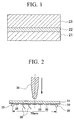
- FIG. 1 is a schematic diagram showing a cross-sectional view of the structure of a thermal barrier coating film to which the thermal barrier coating material according to an embodiment of the present invention is applied.
- the thermal barrier coating film includes a bond coat layer (a metal bonding layer) 22, which is laminated on a high temperature heat-resistant alloy base material 21 for, for instance, a rotor vane, and a ceramic layer 23, which is laminated on the bond coat layer 22.
- the bond coat layer 22 is made into a film using a high temperature corrosion resistant alloy according to an embodiment of the present invention having excellent corrosion resistance and oxidation resistance.
- the ceramic layer 23 is formed by using a ceramics material, such as ZrO 2 partially stabilized by Y 2 O 3 (yttria partially stabilized zirconium, YSZ).
- the bond coat layer 22 decreases the difference in the thermal expansion coefficient between the base material 21 and the ceramic layer 23 to relieve the thermal stress, and prevents the ceramic layer 23 from being separated from the bond coat layer 22. Also, the bond coat layer 22 prevents the oxidation and corrosion of the base material 21.
- the bond coat layer 22 may be formed using, for instance, a low pressure plasma thermal spraying method, a high velocity flame spraying method, and an electron beam physical vapor deposition method.
- the bond coat layer 22 used for the thermal barrier coating film shown in FIG. 1 is characterized by the fact that it is formed by using the high temperature corrosion resistant alloy according to an embodiment of the present invention, and any one of the above-mentioned spraying and deposition methods. That is, a bond coat layer having excellent oxidation resistance, corrosion resistance, and ductility is realized by using the high temperature corrosion resistant alloy including 0.1-12% by weight of Co, 10-30% by weight of Cr, 4-15% by weight of Al, 0.1-5% by weight of Y, and 0.5-10% by weight of Re, and the rest of the alloy is substantially formed by Ni.
- the above-mentioned bond coat layer 22 can be made into a film by using a powder of the high temperature corrosion resistant alloy having the above-mentioned range of composition, and thermal spraying or depositing it on the base material 21.
- the film is made using the low pressure plasma thermal spraying method, it becomes possible to form a more dense bond coat layer 22. Accordingly, a thermal barrier coating film having excellent oxidation resistance and corrosion resistance can be produced.
- the ceramic layer 23 may be formed by using, other than the above-mentioned YSZ, ZrO 2 which is partially stabilized or completely stabilized by Er 2 O 3 , Yb 2 O 3 , Sc 2 O 3 , and so forth.
- examples of the ceramics materials other than ZrO 2 include Al 2 O 3 , and La 2 Zr 2 O 7 . Since the bond coat layer 22 having the above configuration has excellent affinity to any of the ceramics materials, the bond coat layer 22 and the ceramic layer 23 are firmly bonded and have excellent thermal shock resistance.
- the ceramic layer 23 may be made as a film using a ZrO 2 -Yb 2 O 3 powder or ingots by the atmospheric pressure plasma thermal spraying method or the electron beam physical vapor deposition method.
- the ZrO 2 -Yb 2 O 3 powder used in the atmospheric pressure plasma thermal spraying may be prepared by the following procedures.
- a powder of ZrO 2 and a predetermined amount of Yb 2 O 3 powder are prepared, and these are mixed in a ball mill together with an appropriate binder, dispersant, etc., to form a slurry. Then, after the slurry is granulated and dried using a spray drier, the granules are subjected to a diffusion heat treatment to form a solid solution, and composite power of ZrO 2 -Yb 2 O 3 is obtained.
- the ceramic layer 23 including Yb 2 O 3 stabilized ZrO 2 is formed. Also, if an electron beam physical deposition method is used instead of the thermal spraying method as a film making method for the ceramic layer 23, an ingot may be used for that purpose, which is obtained by sintering or electro-melting and solidifying a raw material having a predetermined composition.
- the thermal barrier coating material having the above-mentioned configuration is useful for application to rotor vanes and stationary vanes of industrial turbines, or to internal cylinders and tail cylinders of combustors.
- the application of the above thermal barrier coating material is not limited to industrial gas turbines, and may be applied to high temperature parts (i.e., parts whose temperature may become high) of vehicle engines or jet planes.
- FIGS. 4 and 5, respectively, are diagrams showing a perspective view of an example of the structure of a turbine vane (a turbine member) to which the above-mentioned thermal barrier coating film according to an embodiment of the present invention may be applied.
- the gas turbine rotor vane 4 shown in FIG. 4 includes a tab tail 41 which is fixed to a disc side, a platform 42, and a vane part 43.
- the gas turbine stationary vane 5 shown in FIG. 5 includes an inner shroud 51, an outer shroud 52, and a vane part 53.
- the vane part 53 includes sealing fin cooling holes 54, a slit 55, and so forth.
- FIG. 6 is a schematic diagram showing a partial cross-sectional view of a gas turbine according to an embodiment of the present invention.
- the gas turbine 6 includes a compressor 61 and a turbine 62 directly connected to the compressor 61.
- the compressor 61 may be constructed as an axial compressor, for example, and increases the pressure of atmospheric air or of a predetermined gas which is drawn as working fluid via an inlet thereof.
- a combustor 63 is connected to an outlet of the compressor 61, and the working fluid discharged from the compressor is heated to a predetermined turbine inlet temperature by the combustor 63.
- the working fluid whose temperature is increased to the predetermined temperature is supplied to the turbine 62.
- a plurality of gas turbine stationary vanes 5 mentioned above are disposed in a casing of the turbine 62.
- the above-mentioned gas turbine rotor vane 4 is attached to a main shaft 64 so as to form a pair with a corresponding stationary vane 5.
- One end of the main shaft 64 is connected to a rotary shaft 65 of the compressor 61, and the other end of the main shaft 64 is connected to a rotary shaft of a power generator which is not shown in the figure.
- a material used for a gas turbine rotor vane is a heat-resistant alloy (for instance, a commercially available alloy material CM247L, a product of Canon maskegon Inc.), and a material used for a gas turbine stationary vane is also a heat-resistant alloy (for instance, a commercially available alloy material IN939, a product of Inco Co.). That is, a heat-resistant alloy, which may be used as the base material for the thermal barrier coating material according an embodiment of the present invention, is generally used. Accordingly, if the thermal barrier coating film according to an embodiment of the present invention is applied to the above turbine vane, a turbine vane having an excellent thermal barrier effect and separation resistance may be obtained.
- a heat-resistant alloy for instance, a commercially available alloy material CM247L, a product of Canon maskegon Inc.
- a material used for a gas turbine stationary vane is also a heat-resistant alloy (for instance, a commercially available alloy material IN939, a product of Inco Co.
- the fact that the turbine vane may be applied to the higher temperature environment means that the temperature of the working fluid may be increased, and hence, the gas turbine efficiency can be improved.
- the metal bonding layer disposed between the ceramic layer and the base material is formed by using the high temperature corrosion resistant alloy composition according to an embodiment of the present invention having excellent oxidation resistance, it becomes possible to obtain a bonding layer having excellent durability, which does not readily separate from the ceramic layer, and oxidation and corrosion thereof is hardly caused even when used under high temperature environment. Accordingly, a thermal barrier coating material having excellent durability, which may be used under higher temperature environment as compared with conventional materials, may be realized.
- a member forming a gas turbine or a gas turbine itself having sufficient durability even under higher temperature environment as compared with conventional environment may be obtained by coating it with the thermal barrier coating film according to an embodiment of the present invention.
- An alloy base material of 5 mm width including Ni, 22% by weight of Cr, 9% by weight of Mo, 8% by weight of Co, and 1.0% by weight of Al, and alloy powder having the composition shown in Table 1 below were prepared, and each sample was obtained by forming an alloy layer of 0.1 mm thickness on the alloy base material using the powder by the low pressure plasma thermal spraying method. Also, besides the simple films indicated as "as coat” in Table 1, heat treatment materials indicated as "heat treat” in Table 1 were prepared by subjecting a film to a heat diffusion treatment at 850°C for 24 hours after being made into a film.
- each of the samples obtained in the above-mentioned manner was cut into a piece of 8 mm x 10 mm, and was subjected to the following three-point bending test to evaluate the ductility of an alloy layer 32 of the sample.
- FIG. 2 is a diagram showing a schematic structural view of a bending test device used for the three-point bending test.
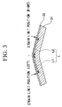
- FIG. 3 is a diagram showing a side view of a sample after the bending test.
- the bending device shown in FIG. 2 includes two supporting pins 35 and 35, and a punch 36.
- the supporting pins 35 and 35 are disposed parallel to each other in a horizontal direction so as to be separated 70 mm away from each other.
- the punch 36 is positioned so that the center axis thereof is located above the center of the line connecting the supporting pins 35 and 35.
- the sample including the alloy layer 32 on the base material 31 is placed on the supporting pins 35 and 35 so that the alloy layer 32 faces the supporting pins 35 and 35. Also, a plurality (seven in FIG.
- strain gauges 38 for measuring the strain of the alloy layer 32 due to the bending are attached to the surface of the alloy layer 32 of the sample mounted on the supporting pins 35 and 35, and a signal line 39 for reading an output signal from the strain gauge 38 is connected to each of the strain gauges 38.
- the punch 36 is contacted to the base material 31 of the sample mounted on the supporting pins 35 and 35, and then moved in a downward direction in the figure for a predetermined distance to bend the sample in a V shape. At that time, the strain generated on the surface of the alloy layer 32 is measured using the strain gauges 38.
- the samples subjected to the test are bent in a V shape as shown in FIG 3, and a crack is generated in the film thickness direction from the position at which the punch 36 was pressed.
- the lengths L1 and L2 were measured, each of which indicates the length of the crack from the center of the sample to the left hand side end (L1), and to the right hand side end (L2) as shown in FIG 3, and the total of L1 and L2 was calculated to obtain a crack generation region length (L), which is indicated as "crack length” in Table 1 below.
- a strain limit value which indicates the limit at which a crack is generated in the alloy layer 32, is obtained from a strain distribution curve based on the results of the measurements using the above-explained strain gauges 38, and this is indicated as "strain limit" in the following Table 1.
- each of the samples 1A through 5B whose composition range satisfies the conditions of the present invention, has a shorter crack generation region length L and a larger strain limit value as compared with the samples 9A and 9B whose alloy layer is made using an alloy which is conventionally used as one having an excellent oxidation resistance. Also, when compared with the samples 10A and 10B whose alloy layer is made using an alloy which is conventionally used as one having an excellent ductility, the crack generation region length L of the samples according to the present invention is shorter, and the strain value thereof is almost the same for the heat treatment material and is better for the as coat material.
- the alloy layers which were formed using the high temperature corrosion resistant alloy material satisfying the composition range of the present invention i.e., 0.1-12% by weight of Co, 10-30% by weight of Cr, 4-15% by weight of Al, 0.1-5% by weight of Y, and 0.5-10% by weight of Re, and the rest is Ni
- the generation of cracks may be efficiently prevented during a thermal spraying process or a heat cycle if a high temperature corrosion resistance material which satisfies the conditions of the present invention is used.
- the high temperature corrosion resistant alloy according to an embodiment of the present invention includes 0.1-12% by weight of Co, 10-30% by weight of Cr, 4-15% by weight of Al, 0.1-5% by weight of Y, and 0.5-10% by weight of Re, and the rest is substantially formed by Ni. If a metal bonding layer of a thermal barrier coating material is formed using the high temperature corrosion resistant alloy, it becomes possible to form a metal bonding layer having excellent ductility. Accordingly it becomes possible to reduce stress applied to a ceramic layer laminated on the metal bonding layer, and hence it becomes possible to prevent separation of the ceramic layer from the metal bonding layer.
- the thermal barrier coating material according to an embodiment of the present invention since it has a metal bonding layer formed by the above-mentioned high temperature corrosion resistant alloy composition of the present invention between a base material and a ceramic layer, has excellent oxidation and corrosion resistance. Also, the ceramic layer of the thermal barrier coating material does not readily separate from the metal bonding layer due to the above-mentioned characteristics thereof.
- the gas turbine member according to an embodiment of the present invention has sufficient durability when used in higher temperature environments as compared with conventional turbine members since it is formed by using the above-mentioned thermal coating material. Hence, a gas turbine member having excellent durability is realized by the present invention. Also, gas whose temperature is higher than conventional temperatures may be used for a gas turbine provided with the gas turbine member according to an embodiment of the present invention. Accordingly, the turbine can be operated highly efficiently.
Landscapes
- Chemical & Material Sciences (AREA)
- Engineering & Computer Science (AREA)
- Metallurgy (AREA)
- Organic Chemistry (AREA)
- Materials Engineering (AREA)
- Mechanical Engineering (AREA)
- Chemical Kinetics & Catalysis (AREA)
- Inorganic Chemistry (AREA)
- Physics & Mathematics (AREA)
- Plasma & Fusion (AREA)
- Ceramic Engineering (AREA)
- Turbine Rotor Nozzle Sealing (AREA)
- Coating By Spraying Or Casting (AREA)
- Other Surface Treatments For Metallic Materials (AREA)
- Physical Vapour Deposition (AREA)
Abstract
Description
| Sample | Powder composition (% by weight) | Crack length L (mm) | Strain limit (%) | |||||||||
| Ni | Co | Cr | Al | Y | Re | Ta | Hf | Si | ||||
| 1A | as coat | bal | 10 | 20 | 6 | 0.3 | 4 | - | - | - | 21.5 | 1.3 |
| 1B | heat treat | 24.7 | 1.0 | |||||||||
| 2A | as coat | bal bal | 10 10 | 17 17 | 4 4 | 0.3 0.3 | 4 4 | - | - | - | 19.0 | 1.5 |
| 2B | heat treat | 17.4 | 1.7 | |||||||||
| 3A | as coat | bal | 10 | 18 | 6 | 0.3 | 5 | - | - | - | 20.4 | 1.4 |
| 3B | heat treat | 17.5 | 1.8 | |||||||||
| 4A | as coat | bal | 10 | 18 | 6 | 0.3 | 6 | - | - | - | 21.1 | 1.3 |
| 4B | heat treat | 17.6 | 1.7 | |||||||||
| 5A | as coat | bal | 10 | 18 | 6.5 | 0.3 | 2 | - | 0.5 | 1 | 18.0 | 1.6 |
| 5B | heat treat | 17.2 | 1.8 | |||||||||
| 6A | as coat | bal | 10 | 15 | 0.3 | 0.3 | - | - | - | 17.7 | 1.7 | |
| 6B | heat treat | 17.0 | 1.9 | |||||||||
| 7A | as coat | bal | 12 | 17 | 4 | 0.3 | 11 | - | - | - | 26.0 | 0.9 |
| 7B | heat treat | 24.9 | 1.0 | |||||||||
| 8A | as coat | bal | 10 | 18 | 6 | 1 | 2 | - | 0.8 | 1.6 | 22.0 | 1.2 |
| 8B | heat treat | 22.3 | 1.2 | |||||||||
| 9A | as coat | bal | 10 | 18 | 6.5 | 0.3 | 2 | 6 | 0.5 | 1 | 28.8 | 0.7 |
| 9B | heat treat | 29.0 | 0.7 | |||||||||
| 10A | as | 32 | | 21 | 8 | 0.5 | - | - | - | - | 26.8 | 0.85 |
| 10B | heat treat | 18.7 | 1.6 | |||||||||
| bal = balance |
Claims (10)
- A high temperature corrosion resistant alloy composition, comprising: Ni, 0.1 to 12% by weight of Co, 10 to 30% by weight of Cr, 4 to 15% by weight of Al, 0.1 to 5% by weight of Y, and 0.5 to 10% by weight of Re.
- A high temperature corrosion resistant alloy composition as set forth in claim 1, wherein said alloy composition comprises 0.5 to 6% by weight of Re.
- A high temperature corrosion resistant alloy composition as set forth in claim 2, wherein said alloy composition comprises 0.5 to 4% by weight of Re.
- A high temperature corrosion resistant alloy composition as set forth in claim 1, wherein said alloy composition comprises 0.01 to 0.7% by weight of Hf and/or 0.01 to 1.5% by weight of Si.
- A thermal barrier coating material, comprising:a heat-resistant alloy base material;a metal bonding layer disposed on said heat-resistant alloy base material, said metal bonding layer formed of a high temperature corrosion resistant alloy composition according to claim 1, anda ceramic layer disposed on said metal bonding layer.
- A thermal barrier coating material as set forth in claim 5, further comprising:an oxidation scale layer comprising Al2O3 as its main constituent formed on said metal bonding layer at a boundary between said metal bonding layer and said ceramic layer, andan oxidation denatured layer formed on said metal bonding layer at a position below said oxidation scale layer, a content of Al of said oxidation denatured layer being lowered due to the formation of said oxidation scale layer, whereinprecipitates including CrRe compounds as its main constituent are contained in said oxidation denatured layer.
- A thermal barrier coating material as set forth in claim 5, wherein
said metal bonding layer is made into a film by a method comprising a step of thermal spraying a powder of a high temperature corrosion resistant alloy composition according to claim 1. - A thermal barrier coating material as set forth in claim 5, wherein
said metal bonding layer is made into a film by a method comprising a step of depositing a high temperature corrosion resistant alloy composition according to claim 1 using an electron beam physical deposition method. - A turbine member comprising: a thermal barrier coating material as set forth in claim 5.
- A gas turbine comprising: a turbine member as set forth in claim 9.
Applications Claiming Priority (2)
| Application Number | Priority Date | Filing Date | Title |
|---|---|---|---|
| JP2001383689 | 2001-12-17 | ||
| JP2001383689A JP4166977B2 (en) | 2001-12-17 | 2001-12-17 | High temperature corrosion resistant alloy material, thermal barrier coating material, turbine member, and gas turbine |
Publications (2)
| Publication Number | Publication Date |
|---|---|
| EP1319730A1 true EP1319730A1 (en) | 2003-06-18 |
| EP1319730B1 EP1319730B1 (en) | 2008-10-22 |
Family
ID=19187617
Family Applications (1)
| Application Number | Title | Priority Date | Filing Date |
|---|---|---|---|
| EP02027556A Expired - Lifetime EP1319730B1 (en) | 2001-12-17 | 2002-12-09 | High temperature corrosion resistant alloy, thermal barrier coating material with metal bonding layer, and gas turbine using high temperature corrosion resistant alloy |
Country Status (6)
| Country | Link |
|---|---|
| US (1) | US6756131B2 (en) |
| EP (1) | EP1319730B1 (en) |
| JP (1) | JP4166977B2 (en) |
| CN (1) | CN1180108C (en) |
| CA (1) | CA2413649C (en) |
| DE (1) | DE60229483D1 (en) |
Cited By (12)
| Publication number | Priority date | Publication date | Assignee | Title |
|---|---|---|---|---|
| EP1541713A1 (en) * | 2003-12-11 | 2005-06-15 | Siemens Aktiengesellschaft | Metallic Protective Coating |
| EP1693473A1 (en) * | 2005-02-18 | 2006-08-23 | Siemens Aktiengesellschaft | MCrAlX-alloy, protective coating made thereof and method for its production |
| EP1707653A1 (en) * | 2005-04-01 | 2006-10-04 | Siemens Aktiengesellschaft | Coating system |
| WO2007074483A1 (en) * | 2005-12-28 | 2007-07-05 | Ansaldo Energia S.P.A. | Alloy composition for the manufacture of protective coatings, its use, process for its application and super-alloy articles coated with the same composition |
| EP1806432A1 (en) * | 2006-01-09 | 2007-07-11 | Siemens Aktiengesellschaft | Coating system with 2 pyrochlore phases |
| EP1837485A1 (en) * | 2006-03-24 | 2007-09-26 | Forschungszentrum Jülich Gmbh | Component with a protective layer |
| EP1840239A1 (en) * | 2006-03-31 | 2007-10-03 | General Electric Company | Machine components and methods of fabricating |
| EP1854898A1 (en) * | 2006-01-17 | 2007-11-14 | Siemens Aktiengesellschaft | Alloy, protective layer and component |
| DE102009010026A1 (en) * | 2009-02-21 | 2010-08-26 | Mtu Aero Engines Gmbh | Component, useful for flow machine, comprises a metal alloy comprising base material, where the component is coated with portion of adhesive layer comprising nickel-chromium-aluminum-yttrium alloy and a surface layer comprising zirconia |
| EP2253738A1 (en) * | 2009-05-22 | 2010-11-24 | United Technologies Corporation | Oxidation-corrosion resistant coating |
| EP2607510A1 (en) * | 2011-12-19 | 2013-06-26 | General Electric Company | Nickel-cobalt-based alloy and bond coat and bond coated articles incorporating the same |
| DE102013214396A1 (en) | 2013-07-23 | 2015-02-19 | Deutsches Zentrum für Luft- und Raumfahrt e.V. | Reactive thermal protection layer for metallic components |
Families Citing this family (46)
| Publication number | Priority date | Publication date | Assignee | Title |
|---|---|---|---|---|
| EP1329592A1 (en) * | 2002-01-18 | 2003-07-23 | Siemens Aktiengesellschaft | Turbine with at least four stages and utilisation of a turbine blade with reduced mass |
| US20050202168A1 (en) * | 2002-08-16 | 2005-09-15 | General Electric Company | Thermally-stabilized thermal barrier coating and process therefor |
| JP3753143B2 (en) * | 2003-03-24 | 2006-03-08 | 大同特殊鋼株式会社 | Ni-based super heat-resistant cast alloy and turbine wheel using the same |
| EP1524334A1 (en) * | 2003-10-17 | 2005-04-20 | Siemens Aktiengesellschaft | Protective coating for protecting a structural member against corrosion and oxidation at high temperatures and structural member |
| US7641985B2 (en) * | 2004-06-21 | 2010-01-05 | Siemens Energy, Inc. | Boron free joint for superalloy component |
| US8004423B2 (en) * | 2004-06-21 | 2011-08-23 | Siemens Energy, Inc. | Instrumented component for use in an operating environment |
| EP1783248A1 (en) * | 2005-11-04 | 2007-05-09 | Siemens Aktiengesellschaft | Two-layer thermal barrier coating system containing a pyrochlore phase |
| EP1790754A1 (en) * | 2005-11-24 | 2007-05-30 | Siemens Aktiengesellschaft | Coating system including a mixed Gadolinium pyrochlor phase. |
| TWI337203B (en) * | 2005-12-30 | 2011-02-11 | Ind Tech Res Inst | Multi metal base thermal resistance alloy and a mold with the multi metal base thermal resistance alloy layer |
| CN100489135C (en) * | 2005-12-31 | 2009-05-20 | 财团法人工业技术研究院 | Multicomponent thermal resistant alloy and mold with multicomponent thermal resistant alloy layer |
| JP4959213B2 (en) * | 2006-03-31 | 2012-06-20 | 三菱重工業株式会社 | Thermal barrier coating member and manufacturing method thereof, thermal barrier coating material, gas turbine, and sintered body |
| US7368827B2 (en) * | 2006-09-06 | 2008-05-06 | Siemens Power Generation, Inc. | Electrical assembly for monitoring conditions in a combustion turbine operating environment |
| US7969323B2 (en) | 2006-09-14 | 2011-06-28 | Siemens Energy, Inc. | Instrumented component for combustion turbine engine |
| US7846243B2 (en) * | 2007-01-09 | 2010-12-07 | General Electric Company | Metal alloy compositions and articles comprising the same |
| JP5647762B2 (en) * | 2007-05-07 | 2015-01-07 | シーメンス アクチエンゲゼルシヤフトSiemens Aktiengesellschaft | Layer structure comprising an outer ceramic layer having a pyrochlore phase and a secondary oxide |
| US8262817B2 (en) * | 2007-06-11 | 2012-09-11 | Honeywell International Inc. | First stage dual-alloy turbine wheel |
| US8797179B2 (en) * | 2007-11-08 | 2014-08-05 | Siemens Aktiengesellschaft | Instrumented component for wireless telemetry |
| US8519866B2 (en) | 2007-11-08 | 2013-08-27 | Siemens Energy, Inc. | Wireless telemetry for instrumented component |
| US9071888B2 (en) * | 2007-11-08 | 2015-06-30 | Siemens Aktiengesellschaft | Instrumented component for wireless telemetry |
| JP2009242836A (en) | 2008-03-28 | 2009-10-22 | Mitsubishi Heavy Ind Ltd | Alloy material having high temperature corrosion-resistance, heat-shielding coating material, turbine member and gas turbine |
| DE102008053222A1 (en) * | 2008-10-25 | 2010-04-29 | Bosch Mahle Turbo Systems Gmbh & Co. Kg | turbocharger |
| CN101768715B (en) * | 2008-12-30 | 2011-09-21 | 沈阳黎明航空发动机(集团)有限责任公司 | Preparation method of an anti-oxidation coating for an aero-engine flame cylinder |
| US8262345B2 (en) * | 2009-02-06 | 2012-09-11 | General Electric Company | Ceramic matrix composite turbine engine |
| CN103314227B (en) * | 2011-01-19 | 2016-05-18 | 西门子公司 | For the sliding bearing and the turbine with this sliding bearing of turbine rotor |
| CN102212786B (en) * | 2011-05-27 | 2013-04-10 | 中国航空工业集团公司北京航空制造工程研究所 | Method for preparing thermal barrier coating |
| US9325388B2 (en) | 2012-06-21 | 2016-04-26 | Siemens Energy, Inc. | Wireless telemetry system including an induction power system |
| DE102013209189A1 (en) * | 2013-05-17 | 2014-11-20 | Siemens Aktiengesellschaft | Protective coating and gas turbine component with the protective coating |
| US9420356B2 (en) | 2013-08-27 | 2016-08-16 | Siemens Energy, Inc. | Wireless power-receiving assembly for a telemetry system in a high-temperature environment of a combustion turbine engine |
| CN103484824B (en) * | 2013-08-27 | 2016-01-20 | 北京航空航天大学 | Compoiste adhering layer material of a kind of anti-1200 DEG C of resistance to combustion gas thermal etchings of high temperature oxidation and preparation method thereof |
| TWI548753B (en) * | 2014-12-30 | 2016-09-11 | 財團法人工業技術研究院 | Composition and coating structure applying with the same |
| CN104831268B (en) * | 2015-04-03 | 2017-06-06 | 航天材料及工艺研究所 | A kind of composite alloy coat preparation method on tantalum-tungsten alloy |
| CN105950926A (en) * | 2015-04-24 | 2016-09-21 | 陈思 | Oil transfer pump for oil refinery |
| CN104762533A (en) * | 2015-05-03 | 2015-07-08 | 张金荣 | An impeller fire pump |
| FR3044945B1 (en) | 2015-12-14 | 2018-01-12 | Centre National De La Recherche Scientifique | ABRADABLE COATING WITH VARIABLE DENSITY |
| FR3044946B1 (en) * | 2015-12-14 | 2018-01-12 | Safran Aircraft Engines | ABRADABLE COATING WITH VARIABLE DENSITY |
| WO2017184762A1 (en) * | 2016-04-20 | 2017-10-26 | Arconic Inc. | Fcc materials of aluminum, cobalt, chromium, and nickel, and products made therefrom |
| CN107385379B (en) * | 2017-07-05 | 2019-05-21 | 西安文理学院 | A kind of preparation method of blast furnace energy recovery turbine blade surface corrosion-proof wear coating |
| CN107630768B (en) * | 2017-08-16 | 2019-09-17 | 上海新力动力设备研究所 | A kind of missile propulsive plant band thermal barrier coating grate structure |
| FR3072717B1 (en) * | 2017-10-20 | 2019-10-11 | Safran | SUPERALLIATION TURBINE PIECE COMPRISING RHENIUM AND METHOD OF MANUFACTURING THE SAME |
| CN107699742A (en) * | 2017-10-23 | 2018-02-16 | 江苏都盛科技发展有限公司 | A kind of High-temperature resistant alloy material |
| CN109626994B (en) * | 2018-11-23 | 2021-12-28 | 昆明理工大学 | Thermal barrier coating material with low infrared transmittance and preparation method thereof |
| CN109538133A (en) * | 2018-12-24 | 2019-03-29 | 天津钢管集团股份有限公司 | A kind of corrosion resisting alloy box cupling and its coating process |
| CN111378935B (en) * | 2019-03-15 | 2022-05-31 | 中国科学院宁波材料技术与工程研究所 | Al/NiCrAlY/Al2O3Composite coating, preparation method and application thereof |
| CN116574397B (en) * | 2023-05-04 | 2024-05-14 | 西安热工研究院有限公司 | A coating composition and its application in anti-scouring and corrosion-resistant coating |
| CN116875922B (en) * | 2023-07-14 | 2025-05-20 | 兰州理工大学 | High-low temperature treatment method for improving wear resistance of nickel-based superalloy finished product |
| CN117604327B (en) * | 2023-12-05 | 2026-04-28 | 华北电力大学 | A protective material for boiler tubes, its preparation method, and a method for protecting boiler tubes. |
Citations (6)
| Publication number | Priority date | Publication date | Assignee | Title |
|---|---|---|---|---|
| EP0412397A1 (en) * | 1989-08-10 | 1991-02-13 | Siemens Aktiengesellschaft | Rhenium-containing protective coating with high corrosion and oxidation resistance |
| WO1996012049A1 (en) * | 1994-10-14 | 1996-04-25 | Siemens Aktiengesellschaft | Protective layer for protecting parts against corrosion, oxidation and excessive thermal stresses, as well as process for producing the same |
| WO1999002745A1 (en) * | 1997-07-10 | 1999-01-21 | Turbocoating S.P.A. | Alloy for corrosion-resistant coatings or surface coatings |
| WO1999023265A1 (en) * | 1997-10-30 | 1999-05-14 | Abb Alstom Power (Schweiz) Ag | Nickel base alloy |
| US5939204A (en) * | 1995-08-16 | 1999-08-17 | Siemens Aktiengesellschaft | Article for transporting a hot, oxidizing gas |
| WO2001072455A1 (en) * | 2000-03-27 | 2001-10-04 | Sulzer Metco (Us) Inc. | Superalloy hvof powders with improved high temperature oxidation, corrosion and creep resistance |
Family Cites Families (2)
| Publication number | Priority date | Publication date | Assignee | Title |
|---|---|---|---|---|
| US5080934A (en) * | 1990-01-19 | 1992-01-14 | Avco Corporation | Process for making abradable hybrid ceramic wall structures |
| US5316866A (en) * | 1991-09-09 | 1994-05-31 | General Electric Company | Strengthened protective coatings for superalloys |
-
2001
- 2001-12-17 JP JP2001383689A patent/JP4166977B2/en not_active Expired - Lifetime
-
2002
- 2002-12-05 CA CA002413649A patent/CA2413649C/en not_active Expired - Fee Related
- 2002-12-09 EP EP02027556A patent/EP1319730B1/en not_active Expired - Lifetime
- 2002-12-09 DE DE60229483T patent/DE60229483D1/en not_active Expired - Lifetime
- 2002-12-11 US US10/316,070 patent/US6756131B2/en not_active Expired - Lifetime
- 2002-12-17 CN CNB021571651A patent/CN1180108C/en not_active Expired - Lifetime
Patent Citations (6)
| Publication number | Priority date | Publication date | Assignee | Title |
|---|---|---|---|---|
| EP0412397A1 (en) * | 1989-08-10 | 1991-02-13 | Siemens Aktiengesellschaft | Rhenium-containing protective coating with high corrosion and oxidation resistance |
| WO1996012049A1 (en) * | 1994-10-14 | 1996-04-25 | Siemens Aktiengesellschaft | Protective layer for protecting parts against corrosion, oxidation and excessive thermal stresses, as well as process for producing the same |
| US5939204A (en) * | 1995-08-16 | 1999-08-17 | Siemens Aktiengesellschaft | Article for transporting a hot, oxidizing gas |
| WO1999002745A1 (en) * | 1997-07-10 | 1999-01-21 | Turbocoating S.P.A. | Alloy for corrosion-resistant coatings or surface coatings |
| WO1999023265A1 (en) * | 1997-10-30 | 1999-05-14 | Abb Alstom Power (Schweiz) Ag | Nickel base alloy |
| WO2001072455A1 (en) * | 2000-03-27 | 2001-10-04 | Sulzer Metco (Us) Inc. | Superalloy hvof powders with improved high temperature oxidation, corrosion and creep resistance |
Cited By (22)
| Publication number | Priority date | Publication date | Assignee | Title |
|---|---|---|---|---|
| EP1541713A1 (en) * | 2003-12-11 | 2005-06-15 | Siemens Aktiengesellschaft | Metallic Protective Coating |
| CN100535166C (en) * | 2003-12-11 | 2009-09-02 | 西门子公司 | metal protective layer |
| US7695827B2 (en) | 2004-12-30 | 2010-04-13 | Siemens Aktiengesellschaft | Component with a protective layer |
| US7261955B2 (en) | 2005-02-18 | 2007-08-28 | Siemens Aktiengesellschaft | MCrAlX alloy and turbine component having protective layer made from MCrAlX alloy |
| EP1693473A1 (en) * | 2005-02-18 | 2006-08-23 | Siemens Aktiengesellschaft | MCrAlX-alloy, protective coating made thereof and method for its production |
| EP1707653A1 (en) * | 2005-04-01 | 2006-10-04 | Siemens Aktiengesellschaft | Coating system |
| US7592071B2 (en) | 2005-04-01 | 2009-09-22 | Siemens Aktiengesellschaft | Layer system |
| WO2007074483A1 (en) * | 2005-12-28 | 2007-07-05 | Ansaldo Energia S.P.A. | Alloy composition for the manufacture of protective coatings, its use, process for its application and super-alloy articles coated with the same composition |
| US9850580B2 (en) | 2005-12-28 | 2017-12-26 | Ansaldo Energia S.P.A. | Alloy composition for the manufacture of protective coatings, its use, process for its application and super-alloy articles coated with the same composition |
| US8920883B2 (en) | 2005-12-28 | 2014-12-30 | Ansaldo Energia S.P.A. | Alloy composition for the manufacture of protective coatings, its use, process for its application and super-alloy articles coated with the same composition |
| US8057924B2 (en) | 2006-01-09 | 2011-11-15 | Siemens Aktiengesellschaft | Layer system comprising two pyrochlore phases |
| EP1806432A1 (en) * | 2006-01-09 | 2007-07-11 | Siemens Aktiengesellschaft | Coating system with 2 pyrochlore phases |
| EP1854899A1 (en) * | 2006-01-17 | 2007-11-14 | Siemens Aktiengesellschaft | Alloy, protective layer and component |
| EP1854898A1 (en) * | 2006-01-17 | 2007-11-14 | Siemens Aktiengesellschaft | Alloy, protective layer and component |
| EP1837485A1 (en) * | 2006-03-24 | 2007-09-26 | Forschungszentrum Jülich Gmbh | Component with a protective layer |
| US7842402B2 (en) | 2006-03-31 | 2010-11-30 | General Electric Company | Machine components and methods of fabricating |
| EP1840239A1 (en) * | 2006-03-31 | 2007-10-03 | General Electric Company | Machine components and methods of fabricating |
| DE102009010026A1 (en) * | 2009-02-21 | 2010-08-26 | Mtu Aero Engines Gmbh | Component, useful for flow machine, comprises a metal alloy comprising base material, where the component is coated with portion of adhesive layer comprising nickel-chromium-aluminum-yttrium alloy and a surface layer comprising zirconia |
| EP2253738A1 (en) * | 2009-05-22 | 2010-11-24 | United Technologies Corporation | Oxidation-corrosion resistant coating |
| US8354176B2 (en) | 2009-05-22 | 2013-01-15 | United Technologies Corporation | Oxidation-corrosion resistant coating |
| EP2607510A1 (en) * | 2011-12-19 | 2013-06-26 | General Electric Company | Nickel-cobalt-based alloy and bond coat and bond coated articles incorporating the same |
| DE102013214396A1 (en) | 2013-07-23 | 2015-02-19 | Deutsches Zentrum für Luft- und Raumfahrt e.V. | Reactive thermal protection layer for metallic components |
Also Published As
| Publication number | Publication date |
|---|---|
| US20030148140A1 (en) | 2003-08-07 |
| CA2413649A1 (en) | 2003-06-17 |
| EP1319730B1 (en) | 2008-10-22 |
| CA2413649C (en) | 2007-04-24 |
| JP4166977B2 (en) | 2008-10-15 |
| DE60229483D1 (en) | 2008-12-04 |
| JP2003183752A (en) | 2003-07-03 |
| CN1180108C (en) | 2004-12-15 |
| CN1427085A (en) | 2003-07-02 |
| US6756131B2 (en) | 2004-06-29 |
Similar Documents
| Publication | Publication Date | Title |
|---|---|---|
| US6756131B2 (en) | High temperature corrosion resistant alloy, thermal barrier coating material, and gas turbine using high temperature corrosion resistant alloy | |
| EP0848077B1 (en) | Thermal barrier coating systems and materials | |
| EP1961833B1 (en) | Thermal barrier coating systems and materials | |
| RU2334022C2 (en) | Protective layer for protection of component part against corrosion and oxidation at high temperatures and component part | |
| US6916551B2 (en) | Thermal barrier coating material, gas turbine parts and gas turbine | |
| JP4959213B2 (en) | Thermal barrier coating member and manufacturing method thereof, thermal barrier coating material, gas turbine, and sintered body | |
| EP1959099B1 (en) | A Method for Manufacturing a Member Coated with a Thermal Barrier | |
| EP1840238A2 (en) | Oxidation-resistant coating and formation method thereof, thermal barrier coating, heat-resistant member, and gas turbine | |
| US5683761A (en) | Alpha alumina protective coatings for bond-coated substrates and their preparation | |
| KR20000057498A (en) | Hot-gas exposable product fitted with a heat-insulating layer and a method for the production thereof | |
| US7666516B2 (en) | Ceramic thermal barrier coating | |
| WO2001018274A1 (en) | In-situ formation of multiphase air plasma sprayed barrier coatings for turbine components | |
| EP1550737A1 (en) | Thermal barrier coatings with improved impact and erosion resistance | |
| CN101302102A (en) | Ceramic powders, ceramic layers and layer systems consisting of two pyrochlore phases and oxides | |
| ITMI20070010A1 (en) | STRATIFORM SYSTEM WITH TWO PIROCLOROUS STAGES | |
| US6231998B1 (en) | Thermal barrier coating | |
| JP4969094B2 (en) | Thermal barrier coating member and production thereof, and gas turbine | |
| US20080131608A1 (en) | Thermal barrier coating material, thermal barrier member, and member coated with thermal barrier and method for manufacturing the same | |
| EP1627862A1 (en) | Ceramic compositions for thermal barrier coatings with improved mechanical properties | |
| JP2003183754A (en) | High-temperature corrosion-resistant alloy material, heat barrier coating material, turbine member and gas turbine | |
| Saha et al. | Application of thermal barrier coating in high temperature resistance | |
| JPH08246901A (en) | Thermal insulation coating film excellent in oxidation resistance | |
| EP1729959A2 (en) | Durable thermal barrier coating having low thermal conductivity |
Legal Events
| Date | Code | Title | Description |
|---|---|---|---|
| PUAI | Public reference made under article 153(3) epc to a published international application that has entered the european phase |
Free format text: ORIGINAL CODE: 0009012 |
|
| 17P | Request for examination filed |
Effective date: 20021209 |
|
| AK | Designated contracting states |
Designated state(s): AT BE BG CH CY CZ DE DK EE ES FI FR GB GR IE IT LI LU MC NL PT SE SI SK TR |
|
| AX | Request for extension of the european patent |
Extension state: AL LT LV MK RO |
|
| AKX | Designation fees paid |
Designated state(s): CH DE FR GB IT LI |
|
| 17Q | First examination report despatched |
Effective date: 20041102 |
|
| GRAP | Despatch of communication of intention to grant a patent |
Free format text: ORIGINAL CODE: EPIDOSNIGR1 |
|
| GRAS | Grant fee paid |
Free format text: ORIGINAL CODE: EPIDOSNIGR3 |
|
| GRAA | (expected) grant |
Free format text: ORIGINAL CODE: 0009210 |
|
| AK | Designated contracting states |
Kind code of ref document: B1 Designated state(s): CH DE FR GB IT LI |
|
| REG | Reference to a national code |
Ref country code: GB Ref legal event code: FG4D |
|
| REG | Reference to a national code |
Ref country code: CH Ref legal event code: NV Representative=s name: E. BLUM & CO. AG PATENT- UND MARKENANWAELTE VSP Ref country code: CH Ref legal event code: EP |
|
| REF | Corresponds to: |
Ref document number: 60229483 Country of ref document: DE Date of ref document: 20081204 Kind code of ref document: P |
|
| PLBE | No opposition filed within time limit |
Free format text: ORIGINAL CODE: 0009261 |
|
| STAA | Information on the status of an ep patent application or granted ep patent |
Free format text: STATUS: NO OPPOSITION FILED WITHIN TIME LIMIT |
|
| 26N | No opposition filed |
Effective date: 20090723 |
|
| REG | Reference to a national code |
Ref country code: DE Ref legal event code: R082 Ref document number: 60229483 Country of ref document: DE Representative=s name: PATENTANWAELTE HENKEL, BREUER & PARTNER, DE Ref country code: DE Ref legal event code: R081 Ref document number: 60229483 Country of ref document: DE Owner name: MITSUBISHI HITACHI POWER SYSTEMS, LTD., YOKOHA, JP Free format text: FORMER OWNER: MITSUBISHI HEAVY INDUSTRIES, LTD., TOKYO, JP |
|
| REG | Reference to a national code |
Ref country code: FR Ref legal event code: PLFP Year of fee payment: 14 |
|
| REG | Reference to a national code |
Ref country code: FR Ref legal event code: CA Effective date: 20151119 |
|
| REG | Reference to a national code |
Ref country code: GB Ref legal event code: 732E Free format text: REGISTERED BETWEEN 20151203 AND 20151209 |
|
| REG | Reference to a national code |
Ref country code: FR Ref legal event code: TP Owner name: MITSUBISHI HITACHI POWER SYSTEMS, LTD., JP Effective date: 20151222 |
|
| PGFP | Annual fee paid to national office [announced via postgrant information from national office to epo] |
Ref country code: CH Payment date: 20151211 Year of fee payment: 14 |
|
| PGFP | Annual fee paid to national office [announced via postgrant information from national office to epo] |
Ref country code: FR Payment date: 20151110 Year of fee payment: 14 |
|
| REG | Reference to a national code |
Ref country code: CH Ref legal event code: PL |
|
| REG | Reference to a national code |
Ref country code: FR Ref legal event code: ST Effective date: 20170831 |
|
| PG25 | Lapsed in a contracting state [announced via postgrant information from national office to epo] |
Ref country code: LI Free format text: LAPSE BECAUSE OF NON-PAYMENT OF DUE FEES Effective date: 20161231 Ref country code: CH Free format text: LAPSE BECAUSE OF NON-PAYMENT OF DUE FEES Effective date: 20161231 Ref country code: FR Free format text: LAPSE BECAUSE OF NON-PAYMENT OF DUE FEES Effective date: 20170102 |
|
| PGFP | Annual fee paid to national office [announced via postgrant information from national office to epo] |
Ref country code: GB Payment date: 20211028 Year of fee payment: 20 Ref country code: DE Payment date: 20211102 Year of fee payment: 20 |
|
| PGFP | Annual fee paid to national office [announced via postgrant information from national office to epo] |
Ref country code: IT Payment date: 20211110 Year of fee payment: 20 |
|
| REG | Reference to a national code |
Ref country code: DE Ref legal event code: R071 Ref document number: 60229483 Country of ref document: DE |
|
| REG | Reference to a national code |
Ref country code: GB Ref legal event code: PE20 Expiry date: 20221208 |
|
| PG25 | Lapsed in a contracting state [announced via postgrant information from national office to epo] |
Ref country code: GB Free format text: LAPSE BECAUSE OF EXPIRATION OF PROTECTION Effective date: 20221208 |