EP1329592A1 - Turbine with at least four stages and utilisation of a turbine blade with reduced mass - Google Patents
Turbine with at least four stages and utilisation of a turbine blade with reduced mass Download PDFInfo
- Publication number
- EP1329592A1 EP1329592A1 EP02001348A EP02001348A EP1329592A1 EP 1329592 A1 EP1329592 A1 EP 1329592A1 EP 02001348 A EP02001348 A EP 02001348A EP 02001348 A EP02001348 A EP 02001348A EP 1329592 A1 EP1329592 A1 EP 1329592A1
- Authority
- EP
- European Patent Office
- Prior art keywords
- turbine
- blade
- ceramic
- blades
- turbine according
- Prior art date
- Legal status (The legal status is an assumption and is not a legal conclusion. Google has not performed a legal analysis and makes no representation as to the accuracy of the status listed.)
- Withdrawn
Links
Images


Classifications
-
- F—MECHANICAL ENGINEERING; LIGHTING; HEATING; WEAPONS; BLASTING
- F01—MACHINES OR ENGINES IN GENERAL; ENGINE PLANTS IN GENERAL; STEAM ENGINES
- F01D—NON-POSITIVE DISPLACEMENT MACHINES OR ENGINES, e.g. STEAM TURBINES
- F01D5/00—Blades; Blade-carrying members; Heating, heat-insulating, cooling or antivibration means on the blades or the members
- F01D5/12—Blades
- F01D5/28—Selecting particular materials; Particular measures relating thereto; Measures against erosion or corrosion
- F01D5/284—Selection of ceramic materials
-
- F—MECHANICAL ENGINEERING; LIGHTING; HEATING; WEAPONS; BLASTING
- F01—MACHINES OR ENGINES IN GENERAL; ENGINE PLANTS IN GENERAL; STEAM ENGINES
- F01D—NON-POSITIVE DISPLACEMENT MACHINES OR ENGINES, e.g. STEAM TURBINES
- F01D5/00—Blades; Blade-carrying members; Heating, heat-insulating, cooling or antivibration means on the blades or the members
- F01D5/12—Blades
- F01D5/14—Form or construction
- F01D5/147—Construction, i.e. structural features, e.g. of weight-saving hollow blades
-
- F—MECHANICAL ENGINEERING; LIGHTING; HEATING; WEAPONS; BLASTING
- F01—MACHINES OR ENGINES IN GENERAL; ENGINE PLANTS IN GENERAL; STEAM ENGINES
- F01D—NON-POSITIVE DISPLACEMENT MACHINES OR ENGINES, e.g. STEAM TURBINES
- F01D5/00—Blades; Blade-carrying members; Heating, heat-insulating, cooling or antivibration means on the blades or the members
- F01D5/12—Blades
- F01D5/28—Selecting particular materials; Particular measures relating thereto; Measures against erosion or corrosion
- F01D5/288—Protective coatings for blades
-
- F—MECHANICAL ENGINEERING; LIGHTING; HEATING; WEAPONS; BLASTING
- F01—MACHINES OR ENGINES IN GENERAL; ENGINE PLANTS IN GENERAL; STEAM ENGINES
- F01D—NON-POSITIVE DISPLACEMENT MACHINES OR ENGINES, e.g. STEAM TURBINES
- F01D5/00—Blades; Blade-carrying members; Heating, heat-insulating, cooling or antivibration means on the blades or the members
- F01D5/30—Fixing blades to rotors; Blade roots ; Blade spacers
- F01D5/3084—Fixing blades to rotors; Blade roots ; Blade spacers the blades being made of ceramics
-
- F—MECHANICAL ENGINEERING; LIGHTING; HEATING; WEAPONS; BLASTING
- F05—INDEXING SCHEMES RELATING TO ENGINES OR PUMPS IN VARIOUS SUBCLASSES OF CLASSES F01-F04
- F05D—INDEXING SCHEME FOR ASPECTS RELATING TO NON-POSITIVE-DISPLACEMENT MACHINES OR ENGINES, GAS-TURBINES OR JET-PROPULSION PLANTS
- F05D2240/00—Components
- F05D2240/80—Platforms for stationary or moving blades
-
- F—MECHANICAL ENGINEERING; LIGHTING; HEATING; WEAPONS; BLASTING
- F05—INDEXING SCHEMES RELATING TO ENGINES OR PUMPS IN VARIOUS SUBCLASSES OF CLASSES F01-F04
- F05D—INDEXING SCHEME FOR ASPECTS RELATING TO NON-POSITIVE-DISPLACEMENT MACHINES OR ENGINES, GAS-TURBINES OR JET-PROPULSION PLANTS
- F05D2300/00—Materials; Properties thereof
- F05D2300/10—Metals, alloys or intermetallic compounds
- F05D2300/15—Rare earth metals, i.e. Sc, Y, lanthanides
-
- F—MECHANICAL ENGINEERING; LIGHTING; HEATING; WEAPONS; BLASTING
- F05—INDEXING SCHEMES RELATING TO ENGINES OR PUMPS IN VARIOUS SUBCLASSES OF CLASSES F01-F04
- F05D—INDEXING SCHEME FOR ASPECTS RELATING TO NON-POSITIVE-DISPLACEMENT MACHINES OR ENGINES, GAS-TURBINES OR JET-PROPULSION PLANTS
- F05D2300/00—Materials; Properties thereof
- F05D2300/20—Oxide or non-oxide ceramics
- F05D2300/21—Oxide ceramics
- F05D2300/2118—Zirconium oxides
-
- F—MECHANICAL ENGINEERING; LIGHTING; HEATING; WEAPONS; BLASTING
- F05—INDEXING SCHEMES RELATING TO ENGINES OR PUMPS IN VARIOUS SUBCLASSES OF CLASSES F01-F04
- F05D—INDEXING SCHEME FOR ASPECTS RELATING TO NON-POSITIVE-DISPLACEMENT MACHINES OR ENGINES, GAS-TURBINES OR JET-PROPULSION PLANTS
- F05D2300/00—Materials; Properties thereof
- F05D2300/20—Oxide or non-oxide ceramics
- F05D2300/22—Non-oxide ceramics
-
- F—MECHANICAL ENGINEERING; LIGHTING; HEATING; WEAPONS; BLASTING
- F05—INDEXING SCHEMES RELATING TO ENGINES OR PUMPS IN VARIOUS SUBCLASSES OF CLASSES F01-F04
- F05D—INDEXING SCHEME FOR ASPECTS RELATING TO NON-POSITIVE-DISPLACEMENT MACHINES OR ENGINES, GAS-TURBINES OR JET-PROPULSION PLANTS
- F05D2300/00—Materials; Properties thereof
- F05D2300/60—Properties or characteristics given to material by treatment or manufacturing
- F05D2300/603—Composites; e.g. fibre-reinforced
-
- Y—GENERAL TAGGING OF NEW TECHNOLOGICAL DEVELOPMENTS; GENERAL TAGGING OF CROSS-SECTIONAL TECHNOLOGIES SPANNING OVER SEVERAL SECTIONS OF THE IPC; TECHNICAL SUBJECTS COVERED BY FORMER USPC CROSS-REFERENCE ART COLLECTIONS [XRACs] AND DIGESTS
- Y02—TECHNOLOGIES OR APPLICATIONS FOR MITIGATION OR ADAPTATION AGAINST CLIMATE CHANGE
- Y02T—CLIMATE CHANGE MITIGATION TECHNOLOGIES RELATED TO TRANSPORTATION
- Y02T50/00—Aeronautics or air transport
- Y02T50/60—Efficient propulsion technologies, e.g. for aircraft
Definitions
- the invention relates to a turbine with at least four Steps according to claim 1 and use of a turbine blade with reduced density according to claim 9.
- Ceramic guide vanes are used because the ceramics are good Has high temperature properties. Especially in the first row behind the combustion chamber (first stage of the turbine) particularly high temperatures occur that only ceramics can endure, with the turbine blades in the first Row are the smallest.
- a ceramic blade is known from US Pat. No. 5,743,713, into a metallic rotor disk of a turbine is used.
- a ceramic blade is known from US Pat. No. 4,563,128, which has a metallic core, the outside with ceramic is covered and up to a radial end of the Shovel stretches.
- the volume fraction of the metallic core is very high.
- Ceramic blades have been used only because of their high temperature resistance in the or temperature critical stages of a turbine used during usually metallic in the subsequent stages Blades (in particular made of Ni-based alloys or made of TiAl alloys) find uses.
- a significant increase in the efficiency of gas turbines can be achieved if at least from the fourth stage Turbine blades e.g. by about 20% compared to one conventional dimensioning can be enlarged. This However, enlargement from the fourth stage leads unchanged speed to a significant increase in Centrifugal forces on the blades, which these and the disks, to which the blades are attached, in an impermissible manner strain.
- the object of the invention is therefore a turbine to show their efficiency compared to using a turbine conventional blading is increased.
- the turbine in the fourth stage has blades with a length of at least 50 cm in length, which have a high proportion of a material with a maximum density of 4 g / cm 3 and are made of ceramic, for example, which means that the Mass is significantly reduced compared to a conventional metallic blading in conventional dimensions. Therefore, the blade length or blade length can be extended considerably compared to metallic blades.
- All-ceramic or hollow ceramic blades can also be used can be used on metallic washers of the Turbine rotor are attached, as is known from the US-PS 5,743,713 is known.
- Another advantage of a lighter shovel is that the mechanical load on the disc on which the blade is attached to the rotation due to the lesser attached mass is smaller.
- FIG. 1 schematically shows a turbine in a longitudinal section, for example a gas turbine 41.
- the invention is not limited to one gas turbine.
- a compressor 47 Along a turbine shaft having a tie rod 4 are a compressor 47, a combustion chamber 50 and a Turbine part 53 arranged one behind the other.
- the turbine part 53 has a hot gas channel 56.
- Gas turbine blades 13, 16 arranged in the hot gas channel 56 are Gas turbine blades 13, 16 arranged. Guide vane and Blade rings are alternately successive intended.
- the gas turbine blades 13, 16 are for example via a combined air and / or Steam cooling cooled.
- the compressor 47 compressor air removed and 63 through an air duct Gas turbine blades 13, 16 supplied.
- Over a Steam feed 66 is the gas turbine blades 13, 16, for example. also fed steam. This steam preferably comes from a steam turbine of a combined gas and Steam process.
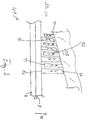
- FIG. 2 shows a section of a gas turbine 41.
- the gas turbine 41 has a turbine shaft with a tie rod 4 which rotates about an axis 7.
- a plurality of guide vanes 13 and a plurality of rotor blades 16 extend, which are arranged, for example, in the hot gas duct 56.
- the first row of guide vanes can be replaced, for example, by a special burner arrangement. Only one example of the blades 16 in the fourth stage is shown here.
- the blades 16 are, for example, on metal disks (25, Fig. 3) on the held together by the tie rod 4 Turbine shaft attached and rotate with the tie rod 4 axis 7.
- the guide vanes 13 are fixed in a rotationally fixed manner to a housing 10 of the gas turbine 41.
- a hot gas 22 flows in the direction of the axis 7 in the drawing from left to right and is shown schematically with an arrow.
- the fourth row of blades in the direction of flow 22 is identified by V4.
- the blades in the fourth stage are blades 16, which have a high material volume fraction made of a material with a maximum density of 4 g / cm 3 and are made of ceramic, for example, and which have a length of at least 50 cm, in particular of at least 65 cm.
- such a ceramic blade Since the density of ceramic materials is in the range of 1.5 to 3.5 g / cm 3 and thus significantly below the densities of nickel-based alloys with 8 g / cm 3 and TiAl alloys of around 4.5 g / cm 3 lies, such a ceramic blade has a significant reduction in mass compared to a corresponding metallic blade, so that when these blades rotate, lower centrifugal forces occur, in particular at the outer radial end 37 of the blade 16 and in particular the foot of the blade 16 and its anchoring in the turbine shaft.
- Ceramic advantageous from different layers of ceramics can exist.
- Oxidic systems can also be used be, e.g. B. mullite fibers or aluminum oxide fibers in a mullite matrix.
- the ceramics can in turn have a protective layer 36 (Fig. 4a) coated against corrosion and oxidation, such as they are known from the metallic turbine blades: Yttrium stabilized zirconium oxide, boron nitride, spinels.
- FIG 3 shows a blade 16 with a length L between Platform 17 and the radial end of the blade 16, the example. made entirely of ceramic and in a metallic Rotor disk 25 is inserted in a rotationally fixed manner.
- the metallic Disc 25 is connected to the tie rod 4 and rotates with him.
- the diameter of the disk 25 is not larger than usual and also not the highest temperatures within the Hot gas channel 56 exposed, so that one like conventional turbine continues to use metal as the material for the Washer 25 can use.
- hybrid turbine blades use that still have a metallic core, the is surrounded by a ceramic, such as from the U.S. Patent 4,563,128 is known.
- the revelation content of this Scripture for the construction of the ceramic turbine blade should expressly be the disclosure content of this application.
- Other types of hybrid blades are conceivable.
- FIG. 4 shows an exemplary hybrid blade 16 Blade 28 is made of ceramic on its outer surface 39. Inside is a metallic core 31, for example Nickel and / or cobalt superalloy available. The metallic core 31 also forms, for example, a foot part 34 of the Bucket 16
- the metallic core extends in the radial direction 19 31 not up to the radial end 37 of the blade 16, but e.g. only up to e.g. 70% of the length of the airfoil 28 in radial direction 19, since otherwise due to the centrifugal forces the intended speed of the turbine Strains the mechanical strength of the metallic core or the blade root or the anchoring in the Turbine shaft would exceed.
- the metallic core 31 can be made at least partially metallic foam to save even more weight to achieve.
- the volume proportion of the material of the ceramic is at least 40% or, for example, also exceeds that of the metallic core 31, so that the blade 16 has a high volume of material Ceramic has.
- the proportion of the ceramic 39 can also predominantly end 37 of the blade 16 are there because the greatest centrifugal forces occur (Fig. 5a).
- a remaining part 38 of the blade 16 consists of metal, for example of a nickel and / or cobalt superalloy.
- the hybrid blade 16 can also be used for further Weight reduction should be hollow inside.
- a scaffold can 40 made of metal for example made of a nickel and / or cobalt superalloy be provided in the ceramic parts be used.
- the scaffold 40 consists, for example, of a leading edge 70 which is formed by the medium is flowed in first in the direction of flow, one Trailing edge 73, the foot part 34 and the tip 76 and the radial end 37.
- the blade 16 can also be hollow inside and through air and / or steam cooled with or without film cooling holes become.
Abstract
Description
Die Erfindung betrifft eine Turbine mit mindestens vier
Stufen gemäß Anspruch 1 und Verwendung einer Turbinenschaufel
mit verringerter Dichte gemäss Anspruch 9.The invention relates to a turbine with at least four
Steps according to
Die Verwendung von keramischen Leitschaufeln in Gasturbinen ist aus der US-PS 3,992,127 bekannt. Keramische Leitschaufeln werden eingesetzt, weil die Keramik gute Hochtemperatureigenschaften aufweist. Insbesondere in der ersten Reihe hinter der Brennkammer (erste Stufe der Turbine) treten besonders hohe Temperaturen auf, die nur Keramiken aushalten können, wobei die Turbinenschaufeln in der ersten Reihe die kleinsten sind.The use of ceramic vanes in gas turbines is known from US Pat. No. 3,992,127. Ceramic guide vanes are used because the ceramics are good Has high temperature properties. Especially in the first row behind the combustion chamber (first stage of the turbine) particularly high temperatures occur that only ceramics can endure, with the turbine blades in the first Row are the smallest.
Aus der US-PS 5,743,713 ist eine keramische Schaufel bekannt, die in eine metallische Läuferscheibe einer Turbine eingesetzt ist.A ceramic blade is known from US Pat. No. 5,743,713, into a metallic rotor disk of a turbine is used.
Aus der US-PS 4,563,128 ist eine keramische Schaufel bekannt, die einen metallischen Kern aufweist, der außen mit Keramik umkleidet ist und sich bis zu einem radialen Ende der Schaufel erstreckt. Der Volumenanteil des metallischen Kerns ist sehr hoch.A ceramic blade is known from US Pat. No. 4,563,128, which has a metallic core, the outside with ceramic is covered and up to a radial end of the Shovel stretches. The volume fraction of the metallic core is very high.
Keramische Laufschaufeln werden bisher nur auf Grund ihrer hohen Temperaturbeständigkeit in der oder den temperaturkritischen Stufen einer Turbine eingesetzt, während in den nachfolgenden Stufen üblicherweise metallische Laufschaufeln (insbesondere aus Ni-Basislegierungen oder aus TiAl-Legierungen) Verwendungen finden.Ceramic blades have been used only because of their high temperature resistance in the or temperature critical stages of a turbine used during usually metallic in the subsequent stages Blades (in particular made of Ni-based alloys or made of TiAl alloys) find uses.
Eine deutliche Steigerung des Wirkungsgrades von Gasturbinen kann erzielt werden, wenn zumindest ab der vierten Stufe die Turbinenlaufschaufeln z.B. um etwa 20% gegenüber einer herkömmlichen Dimensionierung vergrößert werden. Diese Vergrößerung ab der vierten Stufe führt allerdings bei unveränderter Drehzahl zu einer erheblichen Zunahme der Fliehkräfte bei den Schaufeln, welche diese und die Scheiben, an denen die Schaufeln befestigt sind, in unzulässiger Weise belasten.A significant increase in the efficiency of gas turbines can be achieved if at least from the fourth stage Turbine blades e.g. by about 20% compared to one conventional dimensioning can be enlarged. This However, enlargement from the fourth stage leads unchanged speed to a significant increase in Centrifugal forces on the blades, which these and the disks, to which the blades are attached, in an impermissible manner strain.
Aufgabe der Erfindung ist es deshalb, eine Turbine aufzuzeigen, deren Wirkungsgrad gegenüber einer Turbine mit herkömmlicher Beschaufelung erhöht ist.The object of the invention is therefore a turbine to show their efficiency compared to using a turbine conventional blading is increased.
Die Aufgabe wird dadurch gelöst, dass die Turbine in der vierten Stufe jeweils Laufschaufeln mit einer Länge von mindestens 50cm Länge aufweist, die einen hohen Anteil von einem Material mit einer Dichte von maximal 4g/cm3 haben und bspw. aus Keramik sind, wodurch die Masse gegenüber einer üblichen metallischen Beschaufelung in herkömmlicher Dimensionierung deutlich verringert ist. Daher kann die Schaufellänge oder Schaufelblattlänge gegenüber metallischen Schaufeln erheblich verlängert werden.The object is achieved in that the turbine in the fourth stage has blades with a length of at least 50 cm in length, which have a high proportion of a material with a maximum density of 4 g / cm 3 and are made of ceramic, for example, which means that the Mass is significantly reduced compared to a conventional metallic blading in conventional dimensions. Therefore, the blade length or blade length can be extended considerably compared to metallic blades.
Es können auch Vollkeramik- oder Hohlkeramikschaufeln verwendet werden, die auf metallischen Scheiben des Turbinenläufers befestigt sind, wie es aus der US-PS 5,743,713 bekannt ist.All-ceramic or hollow ceramic blades can also be used can be used on metallic washers of the Turbine rotor are attached, as is known from the US-PS 5,743,713 is known.
Ebenso vorteilhaft ist es, keramische Laufschaufeln zu verwenden, die einen metallischen Kern aufweisen, der von Keramik umgeben ist. Dabei ist der Volumenanteil der Keramik sehr hoch, so dass gegenüber einer rein metallischen Schaufel mit einer eventuell vorhandenen dünnen keramischen Schutzschicht eine deutlich geringere Masse vorhanden ist.It is also advantageous to close ceramic blades use that have a metallic core that of Ceramic is surrounded. Here is the volume fraction of the ceramic very high, so compared to a purely metallic shovel with a possibly existing thin ceramic Protective layer a significantly lower mass is present.
Ein weiterer Vorteil einer leichteren Schaufel ist es, dass die mechanische Belastung der Scheibe, an der die Schaufel befestigt ist, bei der Rotation aufgrund der geringeren anhängenden Masse kleiner ist. Another advantage of a lighter shovel is that the mechanical load on the disc on which the blade is attached to the rotation due to the lesser attached mass is smaller.
In den Figuren ist die Erfindung schematisch dargestellt und wird nachfolgend mit weiteren Einzelheiten und vorteilhaften Weiterbildungen näher erläutert.The invention is shown schematically in the figures and will be discussed below with further details and advantages Further training explained.
Es zeigen
Figur 1 zeigt schematisch in einem Längsschnitt eine Turbine, bspw. eine Gasturbine 41. Die Erfindung ist aber nicht beschränkt auf eine Gasturbine.FIG. 1 schematically shows a turbine in a longitudinal section, for example a gas turbine 41. However, the invention is not limited to one gas turbine.
Entlang einer einen Zuganker 4 aufweisenden Turbinenwelle
sind ein Verdichter 47, eine Brennkammer 50 und ein
Turbinenteil 53 hintereinander angeordnet. Das Turbinenteil
53 weist einen Heissgaskanal 56 auf. Im Heissgaskanal 56 sind
Gasturbinenschaufeln 13, 16 angeordnet. Leitschaufel- und
Laufschaufelkränze sind wechselnd aufeinanderfolgend
vorgesehen. Die Gasturbinenschaufeln 13, 16 werden
beispielsweise über eine kombinierte Luft- und/oder
Dampfkühlung gekühlt. Dazu wird beispielsweise dem Verdichter
47 Verdichterluft entnommen und über eine Luftführung 63 den
Gasturbinenschaufeln 13, 16 zugeführt. Über eine
Dampfzuführung 66 wird den Gasturbinenschaufeln 13, 16 bspw.
auch Dampf zugeführt. Vorzugsweise stammt dieser Dampf aus
einer Dampfturbine eines kombinierten Gas- und
Dampfprozesses. Along a turbine shaft having a
Figur 2 zeigt einen Ausschnitt einer Gasturbine 41. Die
Gasturbine 41 hat eine Turbinenwelle mit einem Zuganker 4,
der sich um eine Achse 7 dreht. In radialer Richtung 19, die
senkrecht zur Achse 7 verläuft, erstrecken sich mehrere
Leitschaufeln 13 und mehrere Laufschaufeln 16, die bspw. in
dem Heissgaskanal 56 angeordnet sind. Es sind mindestens vier
Laufschaufelreihen und bspw. vier Leitschaufelreihen, also
vier Stufen vorhanden. Die erste Leitschaufelreihe kann bspw.
durch eine spezielle Brenneranordnung ersetzt werden.
Von den Schaufeln 16 in der vierten Stufe ist hier nur eine
beispielhaft dargestellt.FIG. 2 shows a section of a gas turbine 41. The gas turbine 41 has a turbine shaft with a
Only one example of the
Die Laufschaufeln 16 sind beispielsweise auf Metallscheiben
(25, Fig. 3) an der durch den Zuganker 4 zusammengehaltenen
Turbinenwelle befestigt und drehen sich mit dem Zuganker 4 um
die Achse 7.The
Die Leitschaufeln 13 sind drehfest an einem Gehäuse 10 der
Gasturbine 41 befestigt.
In Richtung der Achse 7 strömt ein Heißgas 22 in der
Zeichnung von links nach rechts und ist mit einem Pfeil
schematisch dargestellt.The
A
Die in Strömungsrichtung 22 vierte Laufschaufelreihe ist mit
V4 gekennzeichnet. Die Laufschaufeln in der vierten Stufe
sind jeweils Laufschaufeln 16, die einen hohen
Materialvolumenanteil aus einem Material mit einer Dichte von
maximal 4g/cm3 haben und bspw. aus Keramik sind und die eine
Länge von mindestens 50cm, insbesondere von mindestens 65cm
aufweisen.The fourth row of blades in the direction of
Da die Dichte von keramischen Werkstoffen im Bereich von 1,5
bis 3,5g/cm3 liegt und damit deutlich unter den Dichten von
Nickel-Basis-Legierungen mit 8g/cm3 und von TiAl-Legierungen
von etwa 4,5g/cm3 liegt, weist eine solche keramische
Laufschaufel eine gegenüber einer entsprechenden metallischen
Laufschaufel deutliche Reduzierung der Masse auf, so dass bei
der Rotation dieser Laufschaufeln geringere Fliehkräfte,
insbesondere am äußeren radialen Ende 37 der Laufschaufel 16
auftreten und insbesondere den Fuß der Laufschaufel 16 und
dessen Verankerung in der Turbinenwelle belasten.Since the density of ceramic materials is in the range of 1.5 to 3.5 g / cm 3 and thus significantly below the densities of nickel-based alloys with 8 g / cm 3 and TiAl alloys of around 4.5 g / cm 3 lies, such a ceramic blade has a significant reduction in mass compared to a corresponding metallic blade, so that when these blades rotate, lower centrifugal forces occur, in particular at the outer
Durch die Verlängerung der Turbinenlaufschaufeln der vierten Reihe um z.B. etwa 20% lässt sich eine erhebliche Steigerung des Wirkungsgrades von Gasturbinen erzielen. Keramische Laufschaufeln sind beispielsweise ganz aus Keramik, wobei die Keramik vorteilhaft aus verschiedenen Schichten von Keramiken bestehen kann. So können faserverstärkte CMC Oxidkeramiken oder faserverstärkte CMC-Nichtoxidkeramiken nicht-oxidische Keramiken wie z. B. Kohlenstofffasern oder SiC-Fasern in einer entsprechenden Kohlenstoff- oder Silizium-Karbid-Matrix verwendet werden. Ebenso können oxidische Systeme verwendet werden, z. B. Mullit-Fasern oder Aluminium-Oxid-Fasern in einer Mullit-Matrix.By extending the turbine blades of the fourth Row around e.g. about 20% can be a significant increase achieve the efficiency of gas turbines. ceramic For example, blades are made entirely of ceramic, the Ceramic advantageous from different layers of ceramics can exist. So fiber-reinforced CMC oxide ceramics or fiber-reinforced non-oxide CMC non-oxide ceramics Ceramics such as B. carbon fibers or SiC fibers in a corresponding carbon or silicon carbide matrix be used. Oxidic systems can also be used be, e.g. B. mullite fibers or aluminum oxide fibers in a mullite matrix.
Die Keramiken können wiederum mit einer Schutzschicht 36 (Fig. 4a) gegen Korrosion und Oxidation beschichtet sein, wie sie von den metallischen Turbinenschaufeln bekannt sind: Yttrium stabilisiertes Zirkonoxid, Bornitrid, Spinelle.The ceramics can in turn have a protective layer 36 (Fig. 4a) coated against corrosion and oxidation, such as they are known from the metallic turbine blades: Yttrium stabilized zirconium oxide, boron nitride, spinels.
Figur 3 zeigt eine Laufschaufel 16 mit einer Länge L zwischen
Plattform 17 und radialem Ende der Laufschaufel 16, die bspw.
vollkommen aus Keramik gebildet und in einer metallischen
Läuferscheibe 25 drehfest eingesetzt ist. Die metallische
Scheibe 25 ist mit dem Zuganker 4 verbunden und dreht sich
mit ihm.Figure 3 shows a
Der Durchmesser der Scheibe 25 ist nicht größer als üblich
und auch nicht den höchsten Temperaturen innerhalb des
Heissgaskanals 56 ausgesetzt, so dass man wie bei einer
herkömmlichen Turbine weiterhin Metall als Material für die
Scheibe 25 verwenden kann. The diameter of the
Ebenso ist es möglich, sogenannte Hybrid-Turbinenschaufeln zu verwenden, die noch einen metallischen Kern aufweisen, der von einer Keramik umgeben ist, wie es beispielsweise aus der US-PS 4,563,128 bekannt ist. Der Offenbarungsgehalt dieser Schrift zum Aufbau der keramischen Turbinenschaufel soll ausdrücklich Offenbarungsgehalt dieser Anmeldung sein. Weitere Arten von Hybridschaufeln sind denkbar.It is also possible to use so-called hybrid turbine blades use that still have a metallic core, the is surrounded by a ceramic, such as from the U.S. Patent 4,563,128 is known. The revelation content of this Scripture for the construction of the ceramic turbine blade should expressly be the disclosure content of this application. Other types of hybrid blades are conceivable.
Figur 4 zeigt eine beispielhafte Hybridschaufel 16. Ein
Schaufelblatt 28 besteht an seiner Aussenfläche aus Keramik
39. Im Innern ist ein metallischer Kern 31 bspw. aus einer
Nickel- und/oder Cobalt-Superlegierung vorhanden. Der
metallische Kern 31 bildet bspw. auch einen Fussteil 34 der
Schaufel 16.FIG. 4 shows an
In radialer Richtung 19 erstreckt sich der metallische Kern
31 nicht bis zum radialen Ende 37 der Schaufel 16, sondern
bspw. nur bis zu z.B. 70% der Länge des Schaufelblatts 28 in
radialer Richtung 19, da sonst die durch die Fliehkräfte bei
der vorgesehenen Drehzahl der Turbine hervorgerufenen
Belastungen die mechanische Festigkeit des metallischen Kerns
oder des Schaufelfußes oder der Verankerung in der
Turbinenwelle übersteigen würden.The metallic core extends in the
Der metallische Kern 31 kann zumindest teilweise aus
metallischen Schaum sein, um eine weitere Gewichtsersparnis
zu erzielen.The
Der Volumenanteil am Material der Keramik beträgt mindestens
40% oder überragt bspw. auch den des metallischen Kerns 31,
so dass die Schaufel 16 einen hohen Materialvolumenanteil aus
Keramik aufweist.The volume proportion of the material of the ceramic is at least
40% or, for example, also exceeds that of the
Der Anteil der Keramik 39 kann sich auch überwiegend am Ende
37 der Schaufel 16 befinden, da dort die grössten Fliehkräfte
auftreten (Fig. 5a). Ein restlicher Teil 38 der Schaufel 16
besteht aus Metall, bspw. aus einer Nickel- und/oder Cobalt-Superlegierung.
Die Hybridschaufel 16 kann auch zur weiteren
Gewichtsreduzierung innen hohl ausgeführt sein.The proportion of the ceramic 39 can also predominantly end
37 of the
Ebenso kann, wie in Figur 5b dargestellt ist, ein Gerüst aus 40 aus Metall bspw. aus einer Nickel- und/oder Cobalt-Superlegierung vorgesehen sein, in das keramische Teile eingesetzt werden.Likewise, as shown in Figure 5b, a scaffold can 40 made of metal, for example made of a nickel and / or cobalt superalloy be provided in the ceramic parts be used.
Das Gerüst 40 besteht bspw. aus einer Vorderkante 70, die von
dem Medium in Strömungsrichtung zuerst angeströmt wird, einer
Hinterkante 73, dem Fussteil 34 und der Spitze 76 sowie dem
radialen Ende 37.The
Die Laufschaufel 16 kann innen auch hohl sein und durch Luft
und/oder Dampfkühlung mit oder ohne Filmkühlbohrungen gekühlt
werden.The
Es ist bisher nicht bekannt, dass man keramische Laufschaufeln in gegenüber herkömmlicher Dimensionierung deutlich vergrößerter Länge auf Grund ihrer geringeren Dichte und der damit verbundenen Reduzierung der Fliehkräfte vorteilhaft zur Steigerung des Turbinenwirkungsgrades einsetzen kann.It is not yet known to be ceramic Blades in comparison to conventional dimensioning significantly increased length due to their lower density and the associated reduction in centrifugal forces advantageous for increasing the turbine efficiency can use.
Claims (11)
die zumindest vier Stufen von aufeinanderfolgend angeordneten Turbinenschaufeln aufweist,
wobei eine Stufe jeweils durch eine Laufschaufelreihe und eine Leitschaufelreihe gebildet ist,
dadurch gekennzeichnet, dass
zumindest die vierte Laufschaufelreihe (V4) Laufschaufeln (16) aufweist, bei denen ein hoher Volumenanteil des Materials eine Dichte von maximal 4g/cm3 aufweist, so dass gegenüber einer metallischen Laufschaufel eine deutlich verringerte Masse vorhanden ist, und
dass die Laufschaufeln (16) eine Mindestlänge von 50cm aufweisen.Turbine, especially gas turbine,
which has at least four stages of successively arranged turbine blades,
a step being formed by a row of moving blades and a row of guide blades,
characterized in that
at least the fourth row of blades (V4) has blades (16) in which a high volume fraction of the material has a density of at most 4 g / cm 3 , so that a significantly reduced mass is present compared to a metallic blade, and
that the blades (16) have a minimum length of 50cm.
dadurch gekennzeichnet, dass
die Laufschaufel (16) jeweils in einer metallischen Läuferscheibe (25) eingesetzt ist.Turbine according to claim 1,
characterized in that
the rotor blade (16) is inserted in a metallic rotor disk (25).
dadurch gekennzeichnet, dass
die Laufschaufel (16) jeweils einen metallischen Kern (31) aufweist, der von Keramik (39) umgeben ist.Turbine according to claim 1,
characterized in that
the rotor blade (16) each has a metallic core (31) which is surrounded by ceramic (39).
dadurch gekennzeichnet, dass
die Laufschaufel (16) jeweils nur aus Keramik (39) ist.Turbine according to claim 1,
characterized in that
the blade (16) is made of ceramic (39) only.
dadurch gekennzeichnet, dass
die Laufschaufel (16) eine Länge von mindestens 65cm aufweist. Turbine according to claim 1,
characterized in that
the blade (16) has a length of at least 65 cm.
dadurch gekennzeichnet, dass
der Volumenanteil der Keramik (39) mindestens 40% beträgt.Turbine according to claim 1,
characterized in that
the volume fraction of the ceramic (39) is at least 40%.
dadurch gekennzeichnet, dass
die Laufschaufel (16) zumindest ab 80% der Länge (L) des Schaufelblatts (28) in radialer Richtung (19) nur noch aus Keramik (39) ist.Turbine according to claim 1,
characterized in that
the rotor blade (16) is at least 80% of the length (L) of the airfoil (28) in the radial direction (19) only made of ceramic (39).
dadurch gekennzeichnet, dass
die Laufschaufel (16) ein metallisches Gerüst (40) aufweist, in das Keramikteile (39) eingesetzt sind.Turbine according to claim 1,
characterized in that
the rotor blade (16) has a metallic frame (40) into which ceramic parts (39) are inserted.
dadurch gekennzeichnet, dass
das Material mit der Dichte von maximal 4g/cm3 eine Keramik oder ein Glas ist.Turbine according to claim 1,
characterized in that
the material with a maximum density of 4 g / cm 3 is a ceramic or a glass.
dadurch gekennzeichnet, dass
das Material mit der Dichte von maximal 4g/cm3 ein kohlenstoffhaltiges Material ist.Turbine according to claim 1,
characterized in that
the material with a maximum density of 4 g / cm 3 is a carbon-containing material.
mit einem hohen Volumenanteil des Materials aus Keramik, mit einer Mindestlänge von 50cm zumindest in der vierten Reihe eines Laufschaufelkranzes (V4) einer Turbine (41) zur Reduzierung der Masse einer Turbinenschaufel (16).Using a turbine blade,
with a high volume fraction of the ceramic material, with a minimum length of 50 cm at least in the fourth row of a rotor blade ring (V4) of a turbine (41) to reduce the mass of a turbine blade (16).
Priority Applications (6)
| Application Number | Priority Date | Filing Date | Title |
|---|---|---|---|
| EP02001348A EP1329592A1 (en) | 2002-01-18 | 2002-01-18 | Turbine with at least four stages and utilisation of a turbine blade with reduced mass |
| US10/501,723 US7229254B2 (en) | 2002-01-18 | 2002-12-18 | Turbine blade with a reduced mass |
| ES02793073T ES2239730T3 (en) | 2002-01-18 | 2002-12-18 | TURBINE WITH AT LEAST FOUR STAGES AND USE OF A TURBINE SHOVEL WITH A REDUCED MASS. |
| EP02793073A EP1466079B1 (en) | 2002-01-18 | 2002-12-18 | Turbine comprising at least four stages and use of a turbine blade with a reduced mass |
| DE50202596T DE50202596D1 (en) | 2002-01-18 | 2002-12-18 | TURBINE WITH AT LEAST FOUR STAGES AND USE OF A TURBINE BLADE WITH REDUCED MASS |
| PCT/EP2002/014499 WO2003060292A1 (en) | 2002-01-18 | 2002-12-18 | Turbine comprising at least four stages and use of a turbine blade with a reduced mass |
Applications Claiming Priority (1)
| Application Number | Priority Date | Filing Date | Title |
|---|---|---|---|
| EP02001348A EP1329592A1 (en) | 2002-01-18 | 2002-01-18 | Turbine with at least four stages and utilisation of a turbine blade with reduced mass |
Publications (1)
| Publication Number | Publication Date |
|---|---|
| EP1329592A1 true EP1329592A1 (en) | 2003-07-23 |
Family
ID=8185307
Family Applications (2)
| Application Number | Title | Priority Date | Filing Date |
|---|---|---|---|
| EP02001348A Withdrawn EP1329592A1 (en) | 2002-01-18 | 2002-01-18 | Turbine with at least four stages and utilisation of a turbine blade with reduced mass |
| EP02793073A Expired - Fee Related EP1466079B1 (en) | 2002-01-18 | 2002-12-18 | Turbine comprising at least four stages and use of a turbine blade with a reduced mass |
Family Applications After (1)
| Application Number | Title | Priority Date | Filing Date |
|---|---|---|---|
| EP02793073A Expired - Fee Related EP1466079B1 (en) | 2002-01-18 | 2002-12-18 | Turbine comprising at least four stages and use of a turbine blade with a reduced mass |
Country Status (5)
| Country | Link |
|---|---|
| US (1) | US7229254B2 (en) |
| EP (2) | EP1329592A1 (en) |
| DE (1) | DE50202596D1 (en) |
| ES (1) | ES2239730T3 (en) |
| WO (1) | WO2003060292A1 (en) |
Cited By (6)
| Publication number | Priority date | Publication date | Assignee | Title |
|---|---|---|---|---|
| US7524162B2 (en) | 2005-03-30 | 2009-04-28 | Alstom Technology Ltd | Rotor for a rotating machine, in particular a steam turbine |
| US8262345B2 (en) | 2009-02-06 | 2012-09-11 | General Electric Company | Ceramic matrix composite turbine engine |
| US8347636B2 (en) | 2010-09-24 | 2013-01-08 | General Electric Company | Turbomachine including a ceramic matrix composite (CMC) bridge |
| US8382436B2 (en) | 2009-01-06 | 2013-02-26 | General Electric Company | Non-integral turbine blade platforms and systems |
| FR3129431A1 (en) * | 2021-11-19 | 2023-05-26 | Safran | ROTOR BLADE FOR AN AIRCRAFT TURBOMACHINE |
| EP2820297B1 (en) * | 2012-02-29 | 2023-08-16 | Raytheon Technologies Corporation | Lightweight fan driving turbine |
Families Citing this family (22)
| Publication number | Priority date | Publication date | Assignee | Title |
|---|---|---|---|---|
| US20080022693A1 (en) * | 2005-09-30 | 2008-01-31 | Zoran Dicic | Ceramic blade gas turbine |
| GB0616832D0 (en) * | 2006-08-25 | 2006-10-04 | Alstom Technology Ltd | Turbomachine |
| EP1970532A1 (en) * | 2007-03-12 | 2008-09-17 | Siemens Aktiengesellschaft | Rotor of a thermal fluid flow engine and gas turbine |
| US20090277175A1 (en) * | 2008-05-09 | 2009-11-12 | Gary Nin Austin | Sodium injection for advanced steam turbines |
| US8075280B2 (en) * | 2008-09-08 | 2011-12-13 | Siemens Energy, Inc. | Composite blade and method of manufacture |
| US9004873B2 (en) * | 2010-12-27 | 2015-04-14 | Rolls-Royce Corporation | Airfoil, turbomachine and gas turbine engine |
| US20120196146A1 (en) * | 2010-12-30 | 2012-08-02 | Edward Claude Rice | Gas turbine engine components including carbon nanofiber composites |
| US8734107B2 (en) * | 2011-05-31 | 2014-05-27 | General Electric Company | Ceramic-based tip cap for a turbine bucket |
| GB201116829D0 (en) * | 2011-09-30 | 2011-11-09 | Rolls Royce Plc | Wear resistant coating and use thereof |
| US8980435B2 (en) | 2011-10-04 | 2015-03-17 | General Electric Company | CMC component, power generation system and method of forming a CMC component |
| EP2679776A1 (en) * | 2012-06-28 | 2014-01-01 | Alstom Technology Ltd | Cooling system and method for an axial flow turbine |
| US9297265B2 (en) * | 2012-12-04 | 2016-03-29 | General Electric Company | Apparatus having engineered surface feature and method to reduce wear and friction between CMC-to-metal attachment and interface |
| US9739157B2 (en) | 2013-03-12 | 2017-08-22 | Rolls-Royce Corporation | Cooled ceramic matrix composite airfoil |
| US9366146B2 (en) | 2013-06-11 | 2016-06-14 | General Electric Company | Closure bucket for turbo-machine |
| DE102013220983A1 (en) * | 2013-10-16 | 2015-04-16 | MTU Aero Engines AG | Blade for a turbomachine |
| WO2015061060A1 (en) * | 2013-10-21 | 2015-04-30 | United Technologies Corporation | Ceramic attachment configuration and method for manufacturing same |
| US10267156B2 (en) * | 2014-05-29 | 2019-04-23 | General Electric Company | Turbine bucket assembly and turbine system |
| US10697305B2 (en) * | 2016-01-08 | 2020-06-30 | General Electric Company | Method for making hybrid ceramic/metal, ceramic/ceramic body by using 3D printing process |
| US10294807B2 (en) | 2016-05-19 | 2019-05-21 | Honeywell International Inc. | Inter-turbine ducts |
| US10577949B2 (en) | 2016-06-15 | 2020-03-03 | General Electric Company | Component for a gas turbine engine |
| DE102016123248A1 (en) * | 2016-12-01 | 2018-06-07 | Rolls-Royce Deutschland Ltd & Co Kg | gas turbine |
| US20190040749A1 (en) * | 2017-08-01 | 2019-02-07 | United Technologies Corporation | Method of fabricating a turbine blade |
Citations (8)
| Publication number | Priority date | Publication date | Assignee | Title |
|---|---|---|---|---|
| FR57426E (en) * | 1946-01-11 | 1953-01-28 | Improvements to gas turbines | |
| GB993412A (en) * | 1961-07-19 | 1965-05-26 | Laporte Acids Ltd | Improvements in or relating to the manufacture of sulphur dioxide |
| GB2027496A (en) * | 1978-08-09 | 1980-02-20 | Mtu Muenchen Gmbh | Turbine blade |
| US4247259A (en) * | 1979-04-18 | 1981-01-27 | Avco Corporation | Composite ceramic/metallic turbine blade and method of making same |
| US4285634A (en) * | 1978-08-09 | 1981-08-25 | Motoren-Und Turbinen-Union Munchen Gmbh | Composite ceramic gas turbine blade |
| US5403153A (en) * | 1993-10-29 | 1995-04-04 | The United States Of America As Represented By The Secretary Of The Air Force | Hollow composite turbine blade |
| US5743713A (en) * | 1995-09-21 | 1998-04-28 | Ngk Insulators, Ltd. | Blade, turbine disc and hybrid type gas turbine blade |
| EP0980961A1 (en) * | 1998-08-07 | 2000-02-23 | Hitachi, Ltd. | Steam turbine blade, method of manufacturing the same, steam turbine power generating plant and low pressure steam turbine |
Family Cites Families (10)
| Publication number | Priority date | Publication date | Assignee | Title |
|---|---|---|---|---|
| USB563412I5 (en) * | 1975-03-28 | 1976-02-24 | ||
| US4063955A (en) * | 1975-10-03 | 1977-12-20 | Gte Sylvania Incorporated | Low thermal expansion ceramics of cordierite solid solution and method for producing same |
| US4111603A (en) * | 1976-05-17 | 1978-09-05 | Westinghouse Electric Corp. | Ceramic rotor blade assembly for a gas turbine engine |
| US4324843A (en) * | 1980-02-13 | 1982-04-13 | United Technologies Corporation | Continuous length silicon carbide fiber reinforced ceramic composites |
| DE3306896A1 (en) * | 1983-02-26 | 1984-08-30 | MTU Motoren- und Turbinen-Union München GmbH, 8000 München | HOT GAS SUPPLIED TURBINE BLADE WITH METAL SUPPORT CORE AND SURROUNDING CERAMIC BLADE |
| DE3639684A1 (en) * | 1986-11-20 | 1988-06-01 | Mtu Muenchen Gmbh | GAS TURBINE ENGINE WITH A GAS GENERATOR |
| US5720597A (en) * | 1996-01-29 | 1998-02-24 | General Electric Company | Multi-component blade for a gas turbine |
| US6280550B1 (en) * | 1998-12-15 | 2001-08-28 | General Electric Company | Fabrication of composite articles having an infiltrated matrix |
| US6514046B1 (en) * | 2000-09-29 | 2003-02-04 | Siemens Westinghouse Power Corporation | Ceramic composite vane with metallic substructure |
| JP4166977B2 (en) * | 2001-12-17 | 2008-10-15 | 三菱重工業株式会社 | High temperature corrosion resistant alloy material, thermal barrier coating material, turbine member, and gas turbine |
-
2002
- 2002-01-18 EP EP02001348A patent/EP1329592A1/en not_active Withdrawn
- 2002-12-18 ES ES02793073T patent/ES2239730T3/en not_active Expired - Lifetime
- 2002-12-18 US US10/501,723 patent/US7229254B2/en not_active Expired - Fee Related
- 2002-12-18 DE DE50202596T patent/DE50202596D1/en not_active Expired - Fee Related
- 2002-12-18 EP EP02793073A patent/EP1466079B1/en not_active Expired - Fee Related
- 2002-12-18 WO PCT/EP2002/014499 patent/WO2003060292A1/en not_active Application Discontinuation
Patent Citations (8)
| Publication number | Priority date | Publication date | Assignee | Title |
|---|---|---|---|---|
| FR57426E (en) * | 1946-01-11 | 1953-01-28 | Improvements to gas turbines | |
| GB993412A (en) * | 1961-07-19 | 1965-05-26 | Laporte Acids Ltd | Improvements in or relating to the manufacture of sulphur dioxide |
| GB2027496A (en) * | 1978-08-09 | 1980-02-20 | Mtu Muenchen Gmbh | Turbine blade |
| US4285634A (en) * | 1978-08-09 | 1981-08-25 | Motoren-Und Turbinen-Union Munchen Gmbh | Composite ceramic gas turbine blade |
| US4247259A (en) * | 1979-04-18 | 1981-01-27 | Avco Corporation | Composite ceramic/metallic turbine blade and method of making same |
| US5403153A (en) * | 1993-10-29 | 1995-04-04 | The United States Of America As Represented By The Secretary Of The Air Force | Hollow composite turbine blade |
| US5743713A (en) * | 1995-09-21 | 1998-04-28 | Ngk Insulators, Ltd. | Blade, turbine disc and hybrid type gas turbine blade |
| EP0980961A1 (en) * | 1998-08-07 | 2000-02-23 | Hitachi, Ltd. | Steam turbine blade, method of manufacturing the same, steam turbine power generating plant and low pressure steam turbine |
Cited By (7)
| Publication number | Priority date | Publication date | Assignee | Title |
|---|---|---|---|---|
| US7524162B2 (en) | 2005-03-30 | 2009-04-28 | Alstom Technology Ltd | Rotor for a rotating machine, in particular a steam turbine |
| US8382436B2 (en) | 2009-01-06 | 2013-02-26 | General Electric Company | Non-integral turbine blade platforms and systems |
| US8262345B2 (en) | 2009-02-06 | 2012-09-11 | General Electric Company | Ceramic matrix composite turbine engine |
| US8347636B2 (en) | 2010-09-24 | 2013-01-08 | General Electric Company | Turbomachine including a ceramic matrix composite (CMC) bridge |
| EP2820297B1 (en) * | 2012-02-29 | 2023-08-16 | Raytheon Technologies Corporation | Lightweight fan driving turbine |
| EP4245965A3 (en) * | 2012-02-29 | 2023-12-20 | RTX Corporation | Lightweight fan driving turbine |
| FR3129431A1 (en) * | 2021-11-19 | 2023-05-26 | Safran | ROTOR BLADE FOR AN AIRCRAFT TURBOMACHINE |
Also Published As
| Publication number | Publication date |
|---|---|
| EP1466079B1 (en) | 2005-03-23 |
| ES2239730T3 (en) | 2005-10-01 |
| US20050069411A1 (en) | 2005-03-31 |
| DE50202596D1 (en) | 2005-04-28 |
| WO2003060292A1 (en) | 2003-07-24 |
| US7229254B2 (en) | 2007-06-12 |
| EP1466079A1 (en) | 2004-10-13 |
Similar Documents
| Publication | Publication Date | Title |
|---|---|---|
| EP1466079B1 (en) | Turbine comprising at least four stages and use of a turbine blade with a reduced mass | |
| DE60028529T2 (en) | Ceramic turbine blades with cooled trailing edge | |
| DE60016058T2 (en) | Cooled turbine shroud | |
| EP1757773B1 (en) | Hollow turbine airfoil | |
| DE102013219774A1 (en) | Shovel for a gas turbine | |
| DE10305912B4 (en) | Hybrid blade for thermal turbomachinery | |
| DE102009003523A1 (en) | Steam turbine blade for low pressure section | |
| EP1512489A1 (en) | Blade for a turbine | |
| EP2320030A1 (en) | Rotor and rotor blade for an axial turbomachine | |
| DE69929490T2 (en) | gas turbine | |
| EP1675702A1 (en) | Gas turbine and rotating blade for a turbomachine | |
| EP3203029A1 (en) | Blade of a turbomachine, having blade foot heat insulation | |
| WO2016087214A1 (en) | Turbine blade, associated rotor, and turbomachine | |
| DE102020115579A1 (en) | GAS TURBINE ENGINE WITH HIGHLY EFFICIENT FAN | |
| DE102019120621A1 (en) | Efficient gas turbine engine | |
| EP1462617A2 (en) | Blading for an axial-flow turbomachine | |
| DE102019120619A1 (en) | AIRPLANE ENGINE WITH HIGH DRIVE AND HEAT EFFICIENCY | |
| DE102019202388A1 (en) | Shroudless blade for a high-speed turbine stage | |
| EP0492207B1 (en) | Blade for flow-machines | |
| DE102019120618A1 (en) | GAS TURBINE | |
| DE102010037688A1 (en) | Fastback turbulator structure and a turbine nozzle containing same | |
| EP1662090B1 (en) | Gas turbine blade | |
| EP1508399B1 (en) | Blade for a turbine engine and method to prevent the crack propagation in a blade for a turbine engine | |
| DE102020209579A1 (en) | HIGH PRESSURE COMPRESSOR SECTION FOR A CYCLE MACHINE AND RELATIVE CYCLE MACHINE, AND METHOD FOR MANUFACTURING A COMPONENT FOR THE HIGH PRESSURE COMPRESSOR SECTION FROM A FIBER COMPOSITE | |
| EP3333366A1 (en) | Turbine blade with leading edge cooling |
Legal Events
| Date | Code | Title | Description |
|---|---|---|---|
| PUAI | Public reference made under article 153(3) epc to a published international application that has entered the european phase |
Free format text: ORIGINAL CODE: 0009012 |
|
| AK | Designated contracting states |
Designated state(s): AT BE CH CY DE DK ES FI FR GB GR IE IT LI LU MC NL PT SE TR |
|
| AX | Request for extension of the european patent |
Extension state: AL LT LV MK RO SI |
|
| AKX | Designation fees paid | ||
| REG | Reference to a national code |
Ref country code: DE Ref legal event code: 8566 |
|
| STAA | Information on the status of an ep patent application or granted ep patent |
Free format text: STATUS: THE APPLICATION IS DEEMED TO BE WITHDRAWN |
|
| 18D | Application deemed to be withdrawn |
Effective date: 20040124 |