EP1319556A1 - Control system and method for battery control unit - Google Patents
Control system and method for battery control unit Download PDFInfo
- Publication number
- EP1319556A1 EP1319556A1 EP01963451A EP01963451A EP1319556A1 EP 1319556 A1 EP1319556 A1 EP 1319556A1 EP 01963451 A EP01963451 A EP 01963451A EP 01963451 A EP01963451 A EP 01963451A EP 1319556 A1 EP1319556 A1 EP 1319556A1
- Authority
- EP
- European Patent Office
- Prior art keywords
- data
- bcu
- battery
- command
- actuator
- Prior art date
- Legal status (The legal status is an assumption and is not a legal conclusion. Google has not performed a legal analysis and makes no representation as to the accuracy of the status listed.)
- Granted
Links
Images


Classifications
-
- B—PERFORMING OPERATIONS; TRANSPORTING
- B60—VEHICLES IN GENERAL
- B60L—PROPULSION OF ELECTRICALLY-PROPELLED VEHICLES; SUPPLYING ELECTRIC POWER FOR AUXILIARY EQUIPMENT OF ELECTRICALLY-PROPELLED VEHICLES; ELECTRODYNAMIC BRAKE SYSTEMS FOR VEHICLES IN GENERAL; MAGNETIC SUSPENSION OR LEVITATION FOR VEHICLES; MONITORING OPERATING VARIABLES OF ELECTRICALLY-PROPELLED VEHICLES; ELECTRIC SAFETY DEVICES FOR ELECTRICALLY-PROPELLED VEHICLES
- B60L58/00—Methods or circuit arrangements for monitoring or controlling batteries or fuel cells, specially adapted for electric vehicles
- B60L58/10—Methods or circuit arrangements for monitoring or controlling batteries or fuel cells, specially adapted for electric vehicles for monitoring or controlling batteries
-
- B—PERFORMING OPERATIONS; TRANSPORTING
- B60—VEHICLES IN GENERAL
- B60R—VEHICLES, VEHICLE FITTINGS, OR VEHICLE PARTS, NOT OTHERWISE PROVIDED FOR
- B60R16/00—Electric or fluid circuits specially adapted for vehicles and not otherwise provided for; Arrangement of elements of electric or fluid circuits specially adapted for vehicles and not otherwise provided for
- B60R16/02—Electric or fluid circuits specially adapted for vehicles and not otherwise provided for; Arrangement of elements of electric or fluid circuits specially adapted for vehicles and not otherwise provided for electric constitutive elements
- B60R16/023—Electric or fluid circuits specially adapted for vehicles and not otherwise provided for; Arrangement of elements of electric or fluid circuits specially adapted for vehicles and not otherwise provided for electric constitutive elements for transmission of signals between vehicle parts or subsystems
-
- H—ELECTRICITY
- H02—GENERATION; CONVERSION OR DISTRIBUTION OF ELECTRIC POWER
- H02J—ELECTRIC POWER NETWORKS; CIRCUIT ARRANGEMENTS OR SYSTEMS FOR SUPPLYING OR DISTRIBUTING ELECTRIC POWER; SYSTEMS FOR STORING ELECTRIC ENERGY
- H02J7/00—Circuit arrangements for charging or discharging batteries or for supplying loads from batteries
- H02J7/80—Circuit arrangements for charging or discharging batteries or for supplying loads from batteries including monitoring or indicating arrangements
-
- H—ELECTRICITY
- H02—GENERATION; CONVERSION OR DISTRIBUTION OF ELECTRIC POWER
- H02J—ELECTRIC POWER NETWORKS; CIRCUIT ARRANGEMENTS OR SYSTEMS FOR SUPPLYING OR DISTRIBUTING ELECTRIC POWER; SYSTEMS FOR STORING ELECTRIC ENERGY
- H02J7/00—Circuit arrangements for charging or discharging batteries or for supplying loads from batteries
- H02J7/80—Circuit arrangements for charging or discharging batteries or for supplying loads from batteries including monitoring or indicating arrangements
- H02J7/82—Control of state of charge [SOC]
-
- B—PERFORMING OPERATIONS; TRANSPORTING
- B60—VEHICLES IN GENERAL
- B60L—PROPULSION OF ELECTRICALLY-PROPELLED VEHICLES; SUPPLYING ELECTRIC POWER FOR AUXILIARY EQUIPMENT OF ELECTRICALLY-PROPELLED VEHICLES; ELECTRODYNAMIC BRAKE SYSTEMS FOR VEHICLES IN GENERAL; MAGNETIC SUSPENSION OR LEVITATION FOR VEHICLES; MONITORING OPERATING VARIABLES OF ELECTRICALLY-PROPELLED VEHICLES; ELECTRIC SAFETY DEVICES FOR ELECTRICALLY-PROPELLED VEHICLES
- B60L2240/00—Control parameters of input or output; Target parameters
- B60L2240/40—Drive Train control parameters
- B60L2240/54—Drive Train control parameters related to batteries
- B60L2240/545—Temperature
-
- B—PERFORMING OPERATIONS; TRANSPORTING
- B60—VEHICLES IN GENERAL
- B60L—PROPULSION OF ELECTRICALLY-PROPELLED VEHICLES; SUPPLYING ELECTRIC POWER FOR AUXILIARY EQUIPMENT OF ELECTRICALLY-PROPELLED VEHICLES; ELECTRODYNAMIC BRAKE SYSTEMS FOR VEHICLES IN GENERAL; MAGNETIC SUSPENSION OR LEVITATION FOR VEHICLES; MONITORING OPERATING VARIABLES OF ELECTRICALLY-PROPELLED VEHICLES; ELECTRIC SAFETY DEVICES FOR ELECTRICALLY-PROPELLED VEHICLES
- B60L2240/00—Control parameters of input or output; Target parameters
- B60L2240/40—Drive Train control parameters
- B60L2240/54—Drive Train control parameters related to batteries
- B60L2240/547—Voltage
-
- B—PERFORMING OPERATIONS; TRANSPORTING
- B60—VEHICLES IN GENERAL
- B60L—PROPULSION OF ELECTRICALLY-PROPELLED VEHICLES; SUPPLYING ELECTRIC POWER FOR AUXILIARY EQUIPMENT OF ELECTRICALLY-PROPELLED VEHICLES; ELECTRODYNAMIC BRAKE SYSTEMS FOR VEHICLES IN GENERAL; MAGNETIC SUSPENSION OR LEVITATION FOR VEHICLES; MONITORING OPERATING VARIABLES OF ELECTRICALLY-PROPELLED VEHICLES; ELECTRIC SAFETY DEVICES FOR ELECTRICALLY-PROPELLED VEHICLES
- B60L2240/00—Control parameters of input or output; Target parameters
- B60L2240/40—Drive Train control parameters
- B60L2240/54—Drive Train control parameters related to batteries
- B60L2240/549—Current
-
- B—PERFORMING OPERATIONS; TRANSPORTING
- B60—VEHICLES IN GENERAL
- B60L—PROPULSION OF ELECTRICALLY-PROPELLED VEHICLES; SUPPLYING ELECTRIC POWER FOR AUXILIARY EQUIPMENT OF ELECTRICALLY-PROPELLED VEHICLES; ELECTRODYNAMIC BRAKE SYSTEMS FOR VEHICLES IN GENERAL; MAGNETIC SUSPENSION OR LEVITATION FOR VEHICLES; MONITORING OPERATING VARIABLES OF ELECTRICALLY-PROPELLED VEHICLES; ELECTRIC SAFETY DEVICES FOR ELECTRICALLY-PROPELLED VEHICLES
- B60L2250/00—Driver interactions
- B60L2250/16—Driver interactions by display
-
- B—PERFORMING OPERATIONS; TRANSPORTING
- B60—VEHICLES IN GENERAL
- B60R—VEHICLES, VEHICLE FITTINGS, OR VEHICLE PARTS, NOT OTHERWISE PROVIDED FOR
- B60R16/00—Electric or fluid circuits specially adapted for vehicles and not otherwise provided for; Arrangement of elements of electric or fluid circuits specially adapted for vehicles and not otherwise provided for
- B60R16/02—Electric or fluid circuits specially adapted for vehicles and not otherwise provided for; Arrangement of elements of electric or fluid circuits specially adapted for vehicles and not otherwise provided for electric constitutive elements
- B60R16/03—Electric or fluid circuits specially adapted for vehicles and not otherwise provided for; Arrangement of elements of electric or fluid circuits specially adapted for vehicles and not otherwise provided for electric constitutive elements for supply of electrical power to vehicle subsystems or for
-
- B—PERFORMING OPERATIONS; TRANSPORTING
- B60—VEHICLES IN GENERAL
- B60Y—INDEXING SCHEME RELATING TO ASPECTS CROSS-CUTTING VEHICLE TECHNOLOGY
- B60Y2200/00—Type of vehicle
- B60Y2200/90—Vehicles comprising electric prime movers
- B60Y2200/91—Electric vehicles
-
- B—PERFORMING OPERATIONS; TRANSPORTING
- B60—VEHICLES IN GENERAL
- B60Y—INDEXING SCHEME RELATING TO ASPECTS CROSS-CUTTING VEHICLE TECHNOLOGY
- B60Y2200/00—Type of vehicle
- B60Y2200/90—Vehicles comprising electric prime movers
- B60Y2200/92—Hybrid vehicles
-
- H—ELECTRICITY
- H02—GENERATION; CONVERSION OR DISTRIBUTION OF ELECTRIC POWER
- H02J—ELECTRIC POWER NETWORKS; CIRCUIT ARRANGEMENTS OR SYSTEMS FOR SUPPLYING OR DISTRIBUTING ELECTRIC POWER; SYSTEMS FOR STORING ELECTRIC ENERGY
- H02J2105/00—Networks for supplying or distributing electric power characterised by their spatial reach or by the load
- H02J2105/30—Networks for supplying or distributing electric power characterised by their spatial reach or by the load the load networks being external to vehicles, i.e. exchanging power with vehicles
- H02J2105/33—Networks for supplying or distributing electric power characterised by their spatial reach or by the load the load networks being external to vehicles, i.e. exchanging power with vehicles exchanging power with road vehicles
-
- Y—GENERAL TAGGING OF NEW TECHNOLOGICAL DEVELOPMENTS; GENERAL TAGGING OF CROSS-SECTIONAL TECHNOLOGIES SPANNING OVER SEVERAL SECTIONS OF THE IPC; TECHNICAL SUBJECTS COVERED BY FORMER USPC CROSS-REFERENCE ART COLLECTIONS [XRACs] AND DIGESTS
- Y02—TECHNOLOGIES OR APPLICATIONS FOR MITIGATION OR ADAPTATION AGAINST CLIMATE CHANGE
- Y02T—CLIMATE CHANGE MITIGATION TECHNOLOGIES RELATED TO TRANSPORTATION
- Y02T10/00—Road transport of goods or passengers
- Y02T10/60—Other road transportation technologies with climate change mitigation effect
- Y02T10/70—Energy storage systems for electromobility, e.g. batteries
-
- Y—GENERAL TAGGING OF NEW TECHNOLOGICAL DEVELOPMENTS; GENERAL TAGGING OF CROSS-SECTIONAL TECHNOLOGIES SPANNING OVER SEVERAL SECTIONS OF THE IPC; TECHNICAL SUBJECTS COVERED BY FORMER USPC CROSS-REFERENCE ART COLLECTIONS [XRACs] AND DIGESTS
- Y02—TECHNOLOGIES OR APPLICATIONS FOR MITIGATION OR ADAPTATION AGAINST CLIMATE CHANGE
- Y02T—CLIMATE CHANGE MITIGATION TECHNOLOGIES RELATED TO TRANSPORTATION
- Y02T90/00—Enabling technologies or technologies with a potential or indirect contribution to GHG emissions mitigation
- Y02T90/10—Technologies relating to charging of electric vehicles
- Y02T90/16—Information or communication technologies improving the operation of electric vehicles
Definitions
- the present invention relates to a control system of a battery control unit (BCU) and a method thereof.
- the present invention relates to a BCU control system and a method thereof used for carrying out various kinds of capability tests, endurance tests, and etc, of an automobile battery provided as a power source of an electric car so as to supply a running motor with driving currents.
- the computer transmits a data transmission command to the BCU at every time that the data is needed, and receives the data responding to the command from the BCU. This results in a problem that a transmission/reception amount for collecting the data becomes large, and as a consequent, charges on the computer and the BCU also become large.
- a BCU control system comprises: an automobile battery; a BCU for controlling an actuator based on a state of the automobile battery; and a computer connected to the BCU by a communication means in a manner capable of performing a data communication therebetween, and a data collection command and an actuator control command being sent from the computer to the BCU.
- the data collection command is transmitted from the computer to the BCU that controls the actuator based on a state of the automobile battery, enabling the computer to display, record, and analyze the data based on the state of the battery in a real time manner.
- the actuator control command is transmitted from the computer to the BCU, thereby automatically controlling the actuator such as a fan, a relay, and so on, for example.
- the data collection command transmitted from the computer to the BCU has been divided into three portions, i.e. a data selection command, a data transmission start command, and a data transmission stop command, enabling the computer to collect the necessary data whenever needed simply by transmitting to the BCU the selection command, the transmission start command, and the transmission stop command.
- the data collection program of the computer is automatically set by using map files for different specifications of the battery, the number of items to be detected, and etc.
- the data communication is performed between the BCU and the computer, it is possible to display and analyze the data in a real time manner, and to interactively control the BCU by transmitting the commands as required. As a result, it becomes possible to easily carry out a test and/or analysis of an operation, and a detection of trouble.
- the data collection command from the computer toward the BCU is divided into three portions, e.g. a data selection, a data transmission start, and a data transmission stop, which eliminates a need to transmit the command from the computer to the BCU in the course of the data collection. This enables to reduce a transmission/reception amount between the two, thus resulting in a high-speed communication.
- a control method of a battery control unit (BCU) for controlling an actuator based on a state of an automobile battery comprises following steps of: (a) transmitting a data transmission command to a the BCU; (b) receiving data from the BCU; (c) storing the data into a buffer; and (d) reading the data from the buffer so as to execute at lease one of a data analysis, a data display, and a graph drawing.
- a control method of a battery control unit (BCU) for controlling an actuator based on a state of an automobile battery comprises following steps of: (a) transmitting an actuator control command to the BCU; (b) receiving data showing a state of the actuator from the BCU; and (c) displaying a state of the actuator according to the data.
- a control method further comprises following steps of: (d) determining whether or not the actuator is properly controlled based on the data; and (e) performing an error display when the actuator is not properly controlled.
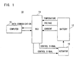
- a BCU control system 10 which is one embodiment of the present invention, shown in Figure 1 - Figure 3 includes an automobile battery 12 constructed as a result of a plurality of battery cells being connected in series, a BCU 14 that calculates various measured data, such as a survival of capacity (SOC), for example, by receiving inputs, e.g. a temperature, voltage, current, and etc. of the battery 12, a computer 16 connected to the BCU 14 by a communication line in a manner capable of performing a data communication therebetween, and an actuator 18 such as a relay, a fan, and so on that protects the automobile battery 12 by being controlled by a control signal from the BCU.
- SOC survival of capacity
- FIG. 2 is a schematic block diagram of a battery system portion 20, and the battery system portion 20 includes the automobile battery 12, the BCU 14 that calculates various kinds of measured data by detecting the voltage, the temperature, and the current of the battery 12, and fans 18A, 18B, and a relay 18C controlled by signals from the BCU 14.
- a running motor (not shown) is connected via an inverter that converts a direct current (DC) into an alternate current (AC).
- the BCU 14 is connected to the computer 16 via a communication line RS232C, thereby rendering possible a data communication.
- Figure 3 is a circuit block diagram showing entire structure of the BCU control system.
- the BCU 14 includes a temperature detection circuit 28 using a thermistor 26, a voltage detection circuit 30 of the battery 12, an electric leakage detection circuit 32, a current detection circuit 36 using a current sensor 34, a relay control circuit 38, a relay adhesion detection circuit 40, a fan control circuit 42, and a microcomputer 44 that calculates various kinds of measured data and control data based on input signals from these circuits.
- the respective data calculated by the microcomputer 44 are sent by a data communication using a communication line to the computer 16.
- the microcomputer 44 includes a CPU, a ROM, an RAM, and etc. for performing required control processes.
- relay control circuit 38 and the fan control circuit 42 control the relay 18C, and the fans 18A and 18B, respectively, via a relay control driver 46 and a fan control driver 48 by control signals from the microcomputer 44. It is noted that an operation power of the BCU 14, the computer 16, and respective circuits, the drivers, and etc. are not illustrated.
- Figure 4 is a flowchart of an operation for performing an initialization process of the computer 16 for the data collection program in the embodiment of the present invention.
- map files in which the number of items to be detected of the temperature, the voltage, and etc. of the battery, and the control information for the fans, the relay, and etc. are filed for each of batteries having different specifications, e.g. a battery A and a battery B, for example, are read into the RAM of the computer 16 so that the number of items to be detected and a control method are automatically set.
- the map file is read into the RAM of the computer 16 in a step S1, and in a step S3, the map file is analyzed by the CPU before selecting a library in a step S5. That is, a screen library by which items are displayed from data type items of the map file is selected.
- a data screen display is set as a display of a graph screen
- a control screen display is set as a display of a control screen of the relay, thereby to complete the initialization process of the data collection program for the computer 16.
- a data collection command from the computer 16 toward the BCU 14 is divided into three, e.g. a data selection command, a data transmission start command, and a data transmission stop command.
- the data selection command is transmitted from the computer 16 to the BCU 14 in a step S11.
- the command is received in a step S13, and the received command is analyzed in a step S15, and then, the transmission data is selected in a step S17.
- the data transmission start command is transmitted from the computer 16 to the BCU 14 in a step S19.
- the BCU 14 receives the command in a step S21, and analyzes the command in a step S23 before continuing transmitting the data in the step S25 until the data transmission stop command is received in a step S49 after transmitting the data in a step S25.
- the computer 16 receives the data in a step S27, stores the data into a buffer (memory) of the computer 16 in a step S29. Furthermore, it is determined whether or not the buffer is overflowed in a step S31. If the result is "YES”, an error process is carried out, and if "NO", the process returns to the step S27 so as to continue receiving the data.
- step S33 the data stored in the buffer in the step S29 is read out in a step S33, and whether or not the data is present or absent is confirmed in a step S35. If the result is "YES”, that is, the data is not present, the process returns to the step S33, and if "NO", that is, the data is present, the process advances to a step S37.
- step S37 It is determined whether or not the data check has been performed in the step S37. If “NO”, that is, the data has not been checked, the process returns to the step S33, and if "YES”, that is, the data has been checked, the data is analyzed in a step S39, the data is displayed on a display of the computer 16 in a step S41, the data is illustrated as a graph in a step S43, and furthermore, the data is saved into the memory in a step S45, and then, the process returns to the step S33.
- the data transmission stop command is transmitted from the computer 16 to the BCU 14 in a step S47, and it is confirmed whether or not the data transmission stop command is received in a step S49. If "YES”, a series of the data receiving operations are ended, and if "NO" in the step S49, the process returns to the step S25 so as to transmit the data from the BCU 14 to the computer 16.
- step numbers of S51 - S73 in Figure 6 correspond to step numbers S81 - S103 in Figure 7, respectively.
- the BCU 14 receives the command in a step S53, analyzes the command in a step S55, and collects the data regarding the fan control in a step S57 so as to determine whether or not the fan is being operated in a step S59. If the result is "YES”, the process determines that the fan is being operated in a step S61, and if "NO", that the fan is being stopped in a step S63. Then, the respective conditions or states of the fans are transmitted to the computer 16 in a step S65.
- the computer 16 receives the state of the fan in a step S67, and displays the state on the screen in a step S69. Then, it is determined whether or not the fan is appropriately controlled in a step S71, and if the result is "YES", the fan control process is ended. If the determination result in the step S71 is "NO”, the error display is performed in a step S73, which ends a series of the fan control processes.
Landscapes
- Engineering & Computer Science (AREA)
- Power Engineering (AREA)
- Mechanical Engineering (AREA)
- Life Sciences & Earth Sciences (AREA)
- Sustainable Development (AREA)
- Sustainable Energy (AREA)
- Transportation (AREA)
- Electric Propulsion And Braking For Vehicles (AREA)
- Charge And Discharge Circuits For Batteries Or The Like (AREA)
- Testing And Monitoring For Control Systems (AREA)
Abstract
Description
Claims (12)
- A control system of a battery control unit (BCU), comprising:an automobile battery;a BCU for controlling an actuator based on a state of said battery; anda computer connected to said BCU by a communication means in a manner capable of performing a data communication therebetween, whereina data collection command and an actuator control command is sent from said computer to said BCU.
- A control system according to claim 1, wherein said actuator includes a fan for said battery.
- A control system according to claim 2, whereinsaid actuator control command includes a fan control command,said BCU transmits to said computer data showing a state of said fan in response to a reception of said fan control command, andsaid computer displays a state of said fan based on said data.
- A control system according to claim 1, wherein said actuator includes a relay for said battery.
- A control system according to claim 4, whereinsaid actuator control command includes a relay control command,said BCU transmits to said computer data showing a state of said relay in response to a reception of said relay control command, andsaid computer displays a state of said relay based on said data.
- A control system according to claim 1, wherein said data collection command includes a data selection command, a data transmission start command, and a data transmission stop command.
- A control system according to claim 6, wherein said BCU transmits to said computer state data showing a state of said battery in response to said data collection command.
- A control system according to claim 7, wherein said state of said battery includes at least a current, a temperature, and a voltage of said battery.
- A control system according to any one of claims 1 to 8, further comprising a map file for automatically setting a data collection program for said computer.
- A control method of a battery control unit (BCU) which controls an actuator based on a state of an automobile battery, comprising following steps of:(a) transmitting a data transmission command to the BCU;(b) receiving data from the BCU;(c) storing the data into a buffer; and(d) reading the data from the buffer so as to execute at least one of a data analysis, a data display, and a graph drawing.
- A control method of a battery control unit (BCU) which controls an actuator based on a state of an automobile battery, comprising following steps of:(a) transmitting an actuator control command to the BCU;(b) receiving data showing a state of the actuator from the BCU; and(c) displaying a state of the actuator according to the data.
- A control method according to claim 11, further comprising steps of:(d) determining based on the data whether or not the actuator is properly controlled; and(e) performing an error display when the actuator is not properly controlled.
Applications Claiming Priority (3)
| Application Number | Priority Date | Filing Date | Title |
|---|---|---|---|
| JP2000281354A JP3594542B2 (en) | 2000-09-18 | 2000-09-18 | BCU control system |
| JP2000281354 | 2000-09-18 | ||
| PCT/JP2001/007713 WO2002024486A1 (en) | 2000-09-18 | 2001-09-05 | Control system and method for battery control unit |
Publications (3)
| Publication Number | Publication Date |
|---|---|
| EP1319556A1 true EP1319556A1 (en) | 2003-06-18 |
| EP1319556A4 EP1319556A4 (en) | 2005-10-05 |
| EP1319556B1 EP1319556B1 (en) | 2007-11-07 |
Family
ID=18766025
Family Applications (1)
| Application Number | Title | Priority Date | Filing Date |
|---|---|---|---|
| EP01963451A Expired - Lifetime EP1319556B1 (en) | 2000-09-18 | 2001-09-05 | Control system and method for battery control unit |
Country Status (7)
| Country | Link |
|---|---|
| US (1) | US6850035B2 (en) |
| EP (1) | EP1319556B1 (en) |
| JP (1) | JP3594542B2 (en) |
| KR (1) | KR100487473B1 (en) |
| CN (1) | CN1230328C (en) |
| DE (1) | DE60131288T2 (en) |
| WO (1) | WO2002024486A1 (en) |
Cited By (4)
| Publication number | Priority date | Publication date | Assignee | Title |
|---|---|---|---|---|
| FR2864302A1 (en) * | 2003-12-19 | 2005-06-24 | Bosch Gmbh Robert | METHOD AND DEVICE FOR SEIZING WEAR OF CONTROL DEVICES |
| WO2009065691A3 (en) * | 2007-11-20 | 2009-08-13 | Zahnradfabrik Friedrichshafen | Method for calculating the efficiency of an energy store, and use of said efficiency |
| US8143853B2 (en) | 2007-02-06 | 2012-03-27 | Batscap | Battery with serial cell modules, and vehicle equipped with the same |
| WO2011135385A3 (en) * | 2010-04-30 | 2013-06-20 | Gyenes Innovations Limited | Rechargeable battery packages |
Families Citing this family (15)
| Publication number | Priority date | Publication date | Assignee | Title |
|---|---|---|---|---|
| CN1317802C (en) * | 2002-08-05 | 2007-05-23 | 财团法人工业技术研究院 | A scalable battery state monitoring circuit for battery management system |
| JP2004184135A (en) * | 2002-11-29 | 2004-07-02 | Sanyo Electric Co Ltd | Battery remaining capacity calculation system |
| JP4416585B2 (en) * | 2004-07-06 | 2010-02-17 | 三洋電機株式会社 | Power supply for vehicle |
| CN1261319C (en) * | 2004-11-11 | 2006-06-28 | 北京电巴科技有限公司 | An electric bus system |
| CA2523240C (en) * | 2005-10-11 | 2009-12-08 | Delaware Systems Inc. | Universal battery module and controller therefor |
| US8380451B2 (en) * | 2009-07-14 | 2013-02-19 | Ford Global Technologies, Llc | System and method for monitoring the state of health of a power electronic system |
| CN102403741A (en) * | 2010-09-13 | 2012-04-04 | 鸿富锦精密工业(深圳)有限公司 | Battery leakage protection circuit |
| CN102496986A (en) * | 2011-12-10 | 2012-06-13 | 常州永旭车辆配件厂 | Charger for electric bicycle |
| CN102496987A (en) * | 2011-12-10 | 2012-06-13 | 常州永旭车辆配件厂 | Charger detection device for electric vehicle |
| CN103568854A (en) * | 2012-07-25 | 2014-02-12 | 光阳工业股份有限公司 | Electric vehicle battery parallel control system |
| KR101628850B1 (en) * | 2014-12-04 | 2016-06-09 | 현대오트론 주식회사 | Battery management system |
| KR101785537B1 (en) * | 2015-02-26 | 2017-10-16 | 주식회사 엘지화학 | System of Verifying function of Secondary Battery Management Apparatus |
| CN106627181A (en) * | 2015-09-10 | 2017-05-10 | 北汽福田汽车股份有限公司 | Battery management system, vehicle with same and method of controlling battery relay |
| KR102114266B1 (en) | 2018-10-30 | 2020-05-22 | 동국대학교 경주캠퍼스 산학협력단 | Fishing float |
| CN115626062B (en) * | 2022-12-21 | 2023-08-04 | 中汽研汽车检验中心(天津)有限公司 | Battery pack temperature early warning method and system based on battery pack thermal management system modeling |
Family Cites Families (18)
| Publication number | Priority date | Publication date | Assignee | Title |
|---|---|---|---|---|
| US4628235A (en) * | 1985-09-19 | 1986-12-09 | Gulf & Western Manufacturing Company | Control circuit for motor driver |
| JP2661018B2 (en) | 1986-09-19 | 1997-10-08 | トヨタ自動車株式会社 | Electric vehicle control device |
| US5422558A (en) * | 1993-05-05 | 1995-06-06 | Astec International Ltd. | Multicell battery power system |
| US5511000A (en) * | 1993-11-18 | 1996-04-23 | Kaloi; Dennis M. | Electronic solid-state record/playback device and system |
| JP3451141B2 (en) * | 1994-11-14 | 2003-09-29 | 本田技研工業株式会社 | Battery temperature controller |
| US5619417A (en) * | 1994-11-23 | 1997-04-08 | Chrysler Corporation | Battery monitoring system for an electric vehicle |
| US5670861A (en) * | 1995-01-17 | 1997-09-23 | Norvik Tractions Inc. | Battery energy monitoring circuits |
| JP3515859B2 (en) * | 1995-09-29 | 2004-04-05 | 株式会社リコー | Battery charge processing device and battery charge processing system |
| DE19545833B4 (en) * | 1995-12-08 | 2005-10-13 | Bayerische Motoren Werke Ag | Battery with several single cells connected in series |
| US5732074A (en) * | 1996-01-16 | 1998-03-24 | Cellport Labs, Inc. | Mobile portable wireless communication system |
| JPH10108379A (en) | 1996-09-30 | 1998-04-24 | Nissan Motor Co Ltd | Charging control system for electric vehicle |
| US6064180A (en) * | 1996-10-29 | 2000-05-16 | General Motors Corporation | Method and apparatus for determining battery state-of-charge using neural network architecture |
| US5739670A (en) * | 1996-10-31 | 1998-04-14 | General Motors Corporation | Method for diagnosing battery condition |
| US6046514A (en) * | 1997-07-25 | 2000-04-04 | 3M Innovative Properties Company | Bypass apparatus and method for series connected energy storage devices |
| JPH1151818A (en) | 1997-08-04 | 1999-02-26 | Nissan Motor Co Ltd | Vehicle diagnostic system |
| JPH1189002A (en) * | 1997-09-09 | 1999-03-30 | Matsushita Electric Ind Co Ltd | Vehicle |
| JP2000173675A (en) | 1998-12-04 | 2000-06-23 | Yazaki Corp | Battery management device for electric vehicles |
| US6307349B1 (en) * | 2000-02-24 | 2001-10-23 | Intermec Ip Corp. | Battery pack having memory |
-
2000
- 2000-09-18 JP JP2000281354A patent/JP3594542B2/en not_active Expired - Lifetime
-
2001
- 2001-09-05 US US10/380,163 patent/US6850035B2/en not_active Expired - Fee Related
- 2001-09-05 KR KR10-2003-7003935A patent/KR100487473B1/en not_active Expired - Fee Related
- 2001-09-05 DE DE60131288T patent/DE60131288T2/en not_active Expired - Lifetime
- 2001-09-05 CN CNB01818703XA patent/CN1230328C/en not_active Expired - Fee Related
- 2001-09-05 WO PCT/JP2001/007713 patent/WO2002024486A1/en not_active Ceased
- 2001-09-05 EP EP01963451A patent/EP1319556B1/en not_active Expired - Lifetime
Cited By (4)
| Publication number | Priority date | Publication date | Assignee | Title |
|---|---|---|---|---|
| FR2864302A1 (en) * | 2003-12-19 | 2005-06-24 | Bosch Gmbh Robert | METHOD AND DEVICE FOR SEIZING WEAR OF CONTROL DEVICES |
| US8143853B2 (en) | 2007-02-06 | 2012-03-27 | Batscap | Battery with serial cell modules, and vehicle equipped with the same |
| WO2009065691A3 (en) * | 2007-11-20 | 2009-08-13 | Zahnradfabrik Friedrichshafen | Method for calculating the efficiency of an energy store, and use of said efficiency |
| WO2011135385A3 (en) * | 2010-04-30 | 2013-06-20 | Gyenes Innovations Limited | Rechargeable battery packages |
Also Published As
| Publication number | Publication date |
|---|---|
| EP1319556A4 (en) | 2005-10-05 |
| CN1230328C (en) | 2005-12-07 |
| US20040027091A1 (en) | 2004-02-12 |
| US6850035B2 (en) | 2005-02-01 |
| EP1319556B1 (en) | 2007-11-07 |
| DE60131288T2 (en) | 2008-08-28 |
| WO2002024486A1 (en) | 2002-03-28 |
| JP2002091548A (en) | 2002-03-29 |
| KR100487473B1 (en) | 2005-05-06 |
| CN1474759A (en) | 2004-02-11 |
| JP3594542B2 (en) | 2004-12-02 |
| KR20030038747A (en) | 2003-05-16 |
| DE60131288D1 (en) | 2007-12-20 |
Similar Documents
| Publication | Publication Date | Title |
|---|---|---|
| US6850035B2 (en) | Control system and method for battery control unit | |
| US5758300A (en) | Diagnosis system for motor vehicles and the method thereof | |
| US9274157B2 (en) | Battery tester for electric vehicle | |
| US11413985B2 (en) | Diagnosis system, diagnosis method, and program | |
| US20080315830A1 (en) | Electronic battery tester or charger with databus connection | |
| CN110456761B (en) | Energy management device testing system and method and vehicle | |
| JP7014132B2 (en) | Abnormality analyzer | |
| CN106585385B (en) | Method and system for detecting relay welding | |
| CN214096607U (en) | Integrated test bench for three-electric-system of pure electric vehicle | |
| JP7648294B2 (en) | Battery management device and method | |
| US12294061B2 (en) | Battery resistance measurement device, vehicle and battery resistance measurement method | |
| CN114734872A (en) | Power consumption habit monitoring equipment of vehicle power battery | |
| CN113064400A (en) | Test refreshing method and device for vehicle controller | |
| JP2009126323A (en) | Fault diagnosis device for vehicles | |
| US6442494B1 (en) | Method and circuit for detecting batteries in a distributed battery network | |
| CN111596248A (en) | Current collecting fault judgment method, device and equipment for current divider and storage medium | |
| KR100440139B1 (en) | Diagnosis method of a hybrid electric vehicle | |
| CN114791563A (en) | Apparatus and method for diagnosing battery failure | |
| JP2000152422A (en) | In-vehicle battery control system | |
| CN117330975A (en) | Battery analysis method, device and storage medium for vehicle | |
| JP7657769B2 (en) | Electricity consumption measurement system, power data management device, driving test management device, electricity consumption measurement method, and program recording medium for electricity consumption measurement system | |
| EP4394410A1 (en) | Specimen testing system, specimen testing program, and specimen testing method | |
| CN115963412B (en) | Systems, methods, and computer program media for detecting and analyzing component failures in battery management systems. | |
| KR102893869B1 (en) | Apparatus and method for testing electric vehicle battery performance | |
| EP4741852A1 (en) | Electrochemical impedance spectroscopy system and method |
Legal Events
| Date | Code | Title | Description |
|---|---|---|---|
| PUAI | Public reference made under article 153(3) epc to a published international application that has entered the european phase |
Free format text: ORIGINAL CODE: 0009012 |
|
| 17P | Request for examination filed |
Effective date: 20030317 |
|
| AK | Designated contracting states |
Designated state(s): DE FR GB IT SE |
|
| A4 | Supplementary search report drawn up and despatched |
Effective date: 20050822 |
|
| RIC1 | Information provided on ipc code assigned before grant |
Ipc: 7H 02J 7/00 B Ipc: 7G 05B 23/02 B Ipc: 7B 60L 3/00 B Ipc: 7B 60L 11/18 A Ipc: 7B 60R 16/04 B |
|
| GRAP | Despatch of communication of intention to grant a patent |
Free format text: ORIGINAL CODE: EPIDOSNIGR1 |
|
| GRAS | Grant fee paid |
Free format text: ORIGINAL CODE: EPIDOSNIGR3 |
|
| GRAA | (expected) grant |
Free format text: ORIGINAL CODE: 0009210 |
|
| AK | Designated contracting states |
Kind code of ref document: B1 Designated state(s): DE FR GB IT SE |
|
| REG | Reference to a national code |
Ref country code: GB Ref legal event code: FG4D |
|
| REF | Corresponds to: |
Ref document number: 60131288 Country of ref document: DE Date of ref document: 20071220 Kind code of ref document: P |
|
| PG25 | Lapsed in a contracting state [announced via postgrant information from national office to epo] |
Ref country code: SE Free format text: LAPSE BECAUSE OF FAILURE TO SUBMIT A TRANSLATION OF THE DESCRIPTION OR TO PAY THE FEE WITHIN THE PRESCRIBED TIME-LIMIT Effective date: 20080207 |
|
| EN | Fr: translation not filed | ||
| PLBE | No opposition filed within time limit |
Free format text: ORIGINAL CODE: 0009261 |
|
| STAA | Information on the status of an ep patent application or granted ep patent |
Free format text: STATUS: NO OPPOSITION FILED WITHIN TIME LIMIT |
|
| 26N | No opposition filed |
Effective date: 20080808 |
|
| PG25 | Lapsed in a contracting state [announced via postgrant information from national office to epo] |
Ref country code: FR Free format text: LAPSE BECAUSE OF FAILURE TO SUBMIT A TRANSLATION OF THE DESCRIPTION OR TO PAY THE FEE WITHIN THE PRESCRIBED TIME-LIMIT Effective date: 20080822 |
|
| GBPC | Gb: european patent ceased through non-payment of renewal fee |
Effective date: 20080905 |
|
| PG25 | Lapsed in a contracting state [announced via postgrant information from national office to epo] |
Ref country code: GB Free format text: LAPSE BECAUSE OF NON-PAYMENT OF DUE FEES Effective date: 20080905 |
|
| PG25 | Lapsed in a contracting state [announced via postgrant information from national office to epo] |
Ref country code: IT Free format text: LAPSE BECAUSE OF NON-PAYMENT OF DUE FEES Effective date: 20080930 |
|
| PGFP | Annual fee paid to national office [announced via postgrant information from national office to epo] |
Ref country code: DE Payment date: 20130829 Year of fee payment: 13 |
|
| REG | Reference to a national code |
Ref country code: DE Ref legal event code: R119 Ref document number: 60131288 Country of ref document: DE |
|
| PG25 | Lapsed in a contracting state [announced via postgrant information from national office to epo] |
Ref country code: DE Free format text: LAPSE BECAUSE OF NON-PAYMENT OF DUE FEES Effective date: 20150401 |