EP1319138B1 - Verfahren zum steuern einer automatischen kraftfahrzeugkupplung - Google Patents
Verfahren zum steuern einer automatischen kraftfahrzeugkupplung Download PDFInfo
- Publication number
- EP1319138B1 EP1319138B1 EP01978144A EP01978144A EP1319138B1 EP 1319138 B1 EP1319138 B1 EP 1319138B1 EP 01978144 A EP01978144 A EP 01978144A EP 01978144 A EP01978144 A EP 01978144A EP 1319138 B1 EP1319138 B1 EP 1319138B1
- Authority
- EP
- European Patent Office
- Prior art keywords
- clutch
- pressure
- accordance
- phase
- control
- Prior art date
- Legal status (The legal status is an assumption and is not a legal conclusion. Google has not performed a legal analysis and makes no representation as to the accuracy of the status listed.)
- Expired - Lifetime
Links
- 238000000034 method Methods 0.000 title claims description 16
- 239000010720 hydraulic oil Substances 0.000 claims description 4
- 230000000694 effects Effects 0.000 claims description 2
- 238000009795 derivation Methods 0.000 claims 1
- 230000002123 temporal effect Effects 0.000 claims 1
- 230000005540 biological transmission Effects 0.000 description 10
- 210000003746 feather Anatomy 0.000 description 8
- 238000010168 coupling process Methods 0.000 description 7
- 230000008878 coupling Effects 0.000 description 5
- 238000005859 coupling reaction Methods 0.000 description 5
- 239000003921 oil Substances 0.000 description 5
- TZCXTZWJZNENPQ-UHFFFAOYSA-L barium sulfate Chemical compound [Ba+2].[O-]S([O-])(=O)=O TZCXTZWJZNENPQ-UHFFFAOYSA-L 0.000 description 3
- 230000001419 dependent effect Effects 0.000 description 2
- 230000018109 developmental process Effects 0.000 description 2
- 238000010586 diagram Methods 0.000 description 2
- 238000005070 sampling Methods 0.000 description 2
- 241001136792 Alle Species 0.000 description 1
- 238000004364 calculation method Methods 0.000 description 1
- 238000011161 development Methods 0.000 description 1
- 238000011156 evaluation Methods 0.000 description 1
- 239000012530 fluid Substances 0.000 description 1
- 238000003780 insertion Methods 0.000 description 1
- 230000037431 insertion Effects 0.000 description 1
- 238000005259 measurement Methods 0.000 description 1
- 230000036316 preload Effects 0.000 description 1
Images




Classifications
-
- F—MECHANICAL ENGINEERING; LIGHTING; HEATING; WEAPONS; BLASTING
- F16—ENGINEERING ELEMENTS AND UNITS; GENERAL MEASURES FOR PRODUCING AND MAINTAINING EFFECTIVE FUNCTIONING OF MACHINES OR INSTALLATIONS; THERMAL INSULATION IN GENERAL
- F16D—COUPLINGS FOR TRANSMITTING ROTATION; CLUTCHES; BRAKES
- F16D48/00—External control of clutches
- F16D48/06—Control by electric or electronic means, e.g. of fluid pressure
- F16D48/066—Control of fluid pressure, e.g. using an accumulator
-
- B—PERFORMING OPERATIONS; TRANSPORTING
- B60—VEHICLES IN GENERAL
- B60W—CONJOINT CONTROL OF VEHICLE SUB-UNITS OF DIFFERENT TYPE OR DIFFERENT FUNCTION; CONTROL SYSTEMS SPECIALLY ADAPTED FOR HYBRID VEHICLES; ROAD VEHICLE DRIVE CONTROL SYSTEMS FOR PURPOSES NOT RELATED TO THE CONTROL OF A PARTICULAR SUB-UNIT
- B60W50/00—Details of control systems for road vehicle drive control not related to the control of a particular sub-unit, e.g. process diagnostic or vehicle driver interfaces
- B60W2050/0001—Details of the control system
- B60W2050/0019—Control system elements or transfer functions
- B60W2050/0028—Mathematical models, e.g. for simulation
- B60W2050/0031—Mathematical model of the vehicle
-
- F—MECHANICAL ENGINEERING; LIGHTING; HEATING; WEAPONS; BLASTING
- F16—ENGINEERING ELEMENTS AND UNITS; GENERAL MEASURES FOR PRODUCING AND MAINTAINING EFFECTIVE FUNCTIONING OF MACHINES OR INSTALLATIONS; THERMAL INSULATION IN GENERAL
- F16D—COUPLINGS FOR TRANSMITTING ROTATION; CLUTCHES; BRAKES
- F16D2500/00—External control of clutches by electric or electronic means
- F16D2500/10—System to be controlled
- F16D2500/104—Clutch
- F16D2500/10406—Clutch position
- F16D2500/10412—Transmission line of a vehicle
-
- F—MECHANICAL ENGINEERING; LIGHTING; HEATING; WEAPONS; BLASTING
- F16—ENGINEERING ELEMENTS AND UNITS; GENERAL MEASURES FOR PRODUCING AND MAINTAINING EFFECTIVE FUNCTIONING OF MACHINES OR INSTALLATIONS; THERMAL INSULATION IN GENERAL
- F16D—COUPLINGS FOR TRANSMITTING ROTATION; CLUTCHES; BRAKES
- F16D2500/00—External control of clutches by electric or electronic means
- F16D2500/30—Signal inputs
- F16D2500/302—Signal inputs from the actuator
- F16D2500/3024—Pressure
-
- F—MECHANICAL ENGINEERING; LIGHTING; HEATING; WEAPONS; BLASTING
- F16—ENGINEERING ELEMENTS AND UNITS; GENERAL MEASURES FOR PRODUCING AND MAINTAINING EFFECTIVE FUNCTIONING OF MACHINES OR INSTALLATIONS; THERMAL INSULATION IN GENERAL
- F16D—COUPLINGS FOR TRANSMITTING ROTATION; CLUTCHES; BRAKES
- F16D2500/00—External control of clutches by electric or electronic means
- F16D2500/70—Details about the implementation of the control system
- F16D2500/704—Output parameters from the control unit; Target parameters to be controlled
- F16D2500/70402—Actuator parameters
- F16D2500/7041—Position
-
- F—MECHANICAL ENGINEERING; LIGHTING; HEATING; WEAPONS; BLASTING
- F16—ENGINEERING ELEMENTS AND UNITS; GENERAL MEASURES FOR PRODUCING AND MAINTAINING EFFECTIVE FUNCTIONING OF MACHINES OR INSTALLATIONS; THERMAL INSULATION IN GENERAL
- F16D—COUPLINGS FOR TRANSMITTING ROTATION; CLUTCHES; BRAKES
- F16D2500/00—External control of clutches by electric or electronic means
- F16D2500/70—Details about the implementation of the control system
- F16D2500/704—Output parameters from the control unit; Target parameters to be controlled
- F16D2500/70402—Actuator parameters
- F16D2500/70418—Current
-
- F—MECHANICAL ENGINEERING; LIGHTING; HEATING; WEAPONS; BLASTING
- F16—ENGINEERING ELEMENTS AND UNITS; GENERAL MEASURES FOR PRODUCING AND MAINTAINING EFFECTIVE FUNCTIONING OF MACHINES OR INSTALLATIONS; THERMAL INSULATION IN GENERAL
- F16D—COUPLINGS FOR TRANSMITTING ROTATION; CLUTCHES; BRAKES
- F16D2500/00—External control of clutches by electric or electronic means
- F16D2500/70—Details about the implementation of the control system
- F16D2500/704—Output parameters from the control unit; Target parameters to be controlled
- F16D2500/70452—Engine parameters
- F16D2500/70462—Opening of the throttle valve
-
- F—MECHANICAL ENGINEERING; LIGHTING; HEATING; WEAPONS; BLASTING
- F16—ENGINEERING ELEMENTS AND UNITS; GENERAL MEASURES FOR PRODUCING AND MAINTAINING EFFECTIVE FUNCTIONING OF MACHINES OR INSTALLATIONS; THERMAL INSULATION IN GENERAL
- F16D—COUPLINGS FOR TRANSMITTING ROTATION; CLUTCHES; BRAKES
- F16D2500/00—External control of clutches by electric or electronic means
- F16D2500/70—Details about the implementation of the control system
- F16D2500/706—Strategy of control
- F16D2500/70668—Signal filtering
Definitions
- the invention relates to a method according to the preamble of claim 1, as known from Z. B. DE-A-19504847.
- a motor vehicle clutch has an actuator for actuating the clutch and an electromagnetically actuated valve, with the coil current, the position of the clutch is set.
- An electronic operating control system for a motor vehicle powertrain contains a so-called coupling electronics, which is said to regulate and control the function of the clutch according to a fixed program depending on different measurement or status message signals. Measures for the case of a sensor error are not provided.
- the invention has for its object to provide a method for controlling an automatically actuated motor vehicle clutch, the function is always secured. In particular, when a position sensor of the clutch operation fails.
- an inverse route model is created on the basis of a control model of the route to be controlled, is controlled with the inverse model of the coil current of the valve valve and is applied to abutting a stop clutch actuator cylinder, the pressure in this cylinder and from a pressure setpoint, a control signal for the actuator generated.
- a motor vehicle drive 1 ( Figure 1) has - as far as it is relevant to the present invention - the following components: a motor 2, a clutch 3, a clutch actuator (hereinafter also referred to as an actuator or actuator for the clutch) 4, a manual transmission 5, a transmission actuator 6, an electronic controller 8 for the actuator 4 and the transmission actuator 6, and a motor controller 9.
- the electronic controller 8 is connected to the actuator 4 through control and signal lines 10 and to the transmission actuator 6 through control and signal lines 11 ,
- the actuator 4 may be formed as an electric motor driven or as a hydraulically driven actuator.
- a hydraulic actuator 4 is used, which is connected to the clutch 3 by a power transmission arrangement 12, which is formed for example as a pressure line.
- the manual transmission 5 is designed as a manual transmission in the present embodiment, but the switching operations are performed automatically and the clutch 3 is - controlled by the electronic control 8 - operated as soon as the controller initiates a switching operation.
- a transmission is called automatic (or automated) Manual gearbox, abbreviated ASG, called.
- the clutch control according to the invention can also be used with automatically controlled clutches (referred to as EKS) for conventional manual transmissions, which are operated as soon as the driver engages the shift lever to perform a gear change, or with fully automatic transmissions, however, usually with a Wet clutch or a flow transducer are provided.
- EKS automatically controlled clutches
- the simplified block diagram (FIG. 2) of a clutch actuation system 14 controlled by the method according to the invention has an electronic control unit 15, to which a number of input quantities 16 are supplied, which are collectively referred to as desired trajectories (or also reference curves).
- the controller 15 then generates at its signal output a control signal in the form of a control or coil current I, which is given to a clutch position system 17, which is designed as an electromagnetic hydraulic valve EVC.
- the input variables are: the setpoint trajectory for the position or position x soll of the clutch (it also corresponds to the position of a known not shown here central release of the clutch) and the setpoint trajectory for the pressure p soll of a hydraulic clutch adjusting cylinder, with which the clutch is actuated and which, because it is well known, is not shown here in detail.
- input variables are the first to third time derivatives dx soll , ddx soll and dddx should be the coupling position and the first derivative dp soll of the target pressure.
- the clutch actuating cylinder is due to the bias of the clutch spring at a stop.
- the pressure in the clutch actuator cylinder controlled in accordance with the predetermined desired trajectory, so that at the end of a pressure build-up phase, the force generated by the cylinder pressure is equal to the spring preload.
- the target trajectory for the pressure p soll is transferred to the controller 15 during the pressure build-up phase together with the derivative ⁇ soll and a signal Modus_1, which indicates a PRINT BUILDING operating mode, and processed by a control algorithm to be described later.
- the controller determines the actuating signal I from this. In the Modus_1 so the cylinder is located at the stop, there is a control of the pressure build-up. In the Modus_2 the cylinder is in motion, there is a control of the clutch position.
- FIG. 3 shows a more detailed track model 20, that is to say a model of the clutch position system 17 to be controlled.
- a hydraulic valve 21 receives as input variables a system pressure P P , a working pressure p A , a tank pressure p T and - via a signal input (1) - the valve or coil current I valve . So that it controls a flow rate Q, which builds up a pressure in a setting cylinder 22 which is positioned a clutch 23, that is in a desired position x for spending, which corresponds to the actual position of the track.
- the built in the actuating cylinder 22 of the clutch 23 pressure p corresponds to the working pressure p A , he also acts on the valve 21 back.
- the desired pressure value p_setpoint and its derivative dp_setpoint are input to a second multiplexer 34.
- program block 35 control PRINT BUILDING from these input signals, a control signal 36, which controls the pressure build-up in the actuating cylinder 22, calculated and applied to the switch 31.
- program blocks 29 and 35 programs are stored, which have been created with a commercially available under the name MATLAB program development tool ("software tool") and with which the clutch position or the pressure build-up are controlled.
- the switch 31 switches either the signal 30 or the signal 36 to its output.
- the respective signal is added in an adder 38 with a dither signal generated in a block 39 to reduce magnetrysteresis and frictional effects in the valve.
- the signal amplitude is limited on both sides and a timer 41, a caused by the function evaluation dead time is displayed.
- a control signal representing the current I is output.
- the distance model 44 of the clutch actuation system is shown in FIG. 5 with the control passage PA open. It has the following blocks: an input 45 to which the system pressure p_P is applied (note: the variables pP, p P and p_P etc. are synonymous, the different notation is based on different notations in different programs used) From there, p_P reaches the positive input an adder 46, at the negative input of the cylinder or working pressure pA is applied. Its output signal is combined in a multiplexer 47 with the coil current I , which is applied to an input 48 to form a vector signal.
- the output of the multiplexer 47 is connected to a block 50, which calculates the volume flow Q and gives it to the plus input of an adder 51 with a negated input. Negated or on its negative input is given a volume change .DELTA.V and the resulting difference is multiplied in a multiplier 52 with the output signal of a Dividiergliedes 54th
- the modulus of elasticity E_Oel reaches the overall arrangement, including the hydraulic oil, which is determined in a block 55 depending on the cylinder pressure.
- the determined in a block 56 depending on the cylinder position volume V of the hydraulic clutch actuation system including the actuator cylinder 22 is set.
- the cylinder pressure is calculated from the output signal of the multiplier 52 and applied to the negative input of the adder 46 and to the input of an amplifier 59 serving as a multiplier. In this he is multiplied by the effective cylinder area A.
- the result arrives at an input of an adder 60, at the second input of which the spring force F spring acting on the actuating cylinder passes, which is calculated in a block 62 from the cylinder position.
- the frictional force F re ih occurring in the actuating cylinder is set, which is determined in a block 63.
- the output signal of the adder 60 reaches an amplifier 64, where it is divided by the moving mass m_z.
- an integrator 66 the result of the division is integrated and thus the cylinder speed is calculated.
- the cylinder position is calculated and applied to the input of the block 62 and the block 56.
- the cylinder speed is applied on the one hand to the input of the block 63 and on the other hand to the input of an amplifier 68 in which it is multiplied by the effective cylinder area A_z.
- the result of the multiplication is a change in volume ⁇ V in the cylinder, which is set to a negative input of the adder 51st
- the volume flow Q is a function of this pressure difference and the valve spool position x v .
- the simplified control model 44 (FIG. 5) is used for the actual control of the clutch position system.
- This results in the volume flow Q as a function of the coil current I and the differential pressure ⁇ p : Q Q s ( I . ⁇ P )
- This function which represents the steady-state flow Q as a function of the two variables I and ⁇ p , is determined numerically. It can be seen in FIG.
- a calculation of the individual blocks of FIG. 5 takes place in an exemplary embodiment according to the following laws.
- the clutch layer is non-linearly controlled as follows because the track is nonlinear.
- the indices z (for cylinder) and oil are left out in the following.
- F spring is the spring force
- F R eih the friction force in the clutch system.
- I d I ( y d . y ⁇ d . y ⁇ d . y ⁇ d . y ⁇ d )
- I d I ( y d . y ⁇ d . 0 . 0 )
- the pressure buildup in the actuator cylinder 22 of the clutch actuation system is controlled as follows.
- the control of the clutch takes place with an inverse path, which is obtained by inverting the route shown with reference to FIG.
- the desired value x soll and the actual value x z of the clutch position are plotted in a control without a pressure build-up phase.
- the desired course is specified according to a typical coupling process.
- the occurring error e is shown.
- the maximum error e is about 3 mm, for the subsequent engagement process (right) over 1 mm.
Landscapes
- Physics & Mathematics (AREA)
- Fluid Mechanics (AREA)
- Engineering & Computer Science (AREA)
- General Engineering & Computer Science (AREA)
- Mechanical Engineering (AREA)
- Hydraulic Clutches, Magnetic Clutches, Fluid Clutches, And Fluid Joints (AREA)
Description
- Die Erfindung betrifft ein Verfahren nach dem Oberbegriff von Patentanspruch 1, wie es Z. B. aus DE-A-19504847 bekannt ist. Eine solche Kraftfahrzeugkupplung weist ein Stellglied zum Betätigen der Kupplung und ein elektromagnetisch betätigtes Ventil auf, mit dessen Spulenstrom die Position der Kupplung festgelegt wird.
- Neben den herkömmlichen durch den Fahrer direkt betätigten Kraftfahrzeugkupplungen werden in Kraftfahrzeugen zunehmend automatisch betätigte Kupplungen eingesetzt (siehe zum Beispiel DE 44 34 111 A1). Bei solchen Kupplungen treten aber Probleme auf, wenn sie ohne Kupplungslagesensor, zum Beispiel bei einem Ausfall des Sensors, gesteuert werden sollen. Da die Kupplung ein sicherheitskritisches Element in einem Kraftfahrzeug ist, muss ihre Funktion auch ohne Funktionsfähigkeit des Sensors ständig gewährleistet sein.
- Ein elektronisches Betriebssteuersystem für einen Kraftfahrzeug-Antriebsstrang (DE 38 31 449 A1) enthält eine sogenannte Kupplungselektronik, von der ausgesagt wird, dass sie die Funktion der Kupplung nach einem festgelegten Programm abhängig von verschiedenen Mess- oder Zustandsmeldesignalen regelt und steuert. Maßnahmen für den Fall eines Sensorfehlers sind dabei nicht vorgesehen.
- Der Erfindung liegt die Aufgabe zugrunde, ein Verfahren zum Steuern einer automatisch betätigten Kraftfahrzeugkupplung zu schaffen, deren Funktion jederzeit gesichert ist. Insbesondere dann, wenn ein Lagesensor der Kupplungsbetätigung ausfällt.
- Die Aufgabe der Erfindung wird durch ein Verfahren nach Patentsanspruch 1 gelöst. Bei dem Verfahren wird anhand eines regeltechnischen Modells der zu steuernden Strecke ein inverses Streckenmodell erstellt, wird mit dem inversen Streckenmodell der Spulenstrom des Ventils gesteuert und wird bei an einem Anschlag anliegenden Kupplungsstellzylinder der Druck in diesem Zylinder aufgebaut und aus einem Drucksollwert ein Steuersignal für das Stellglied erzeugt.
- Zweckmäßige Weiterbildungen der Erfindung sind in den Unteransprüchen niedergelegt.
- Die Vorteile der Erfindung liegen insbesondere darin, dass sie eine einfache Realisierung eines Notfahrprogramms bei Ausfall des Kupplungspositionssensors ergibt.
- Ausführungsbeispiele der Erfindung werden im folgenden anhand der Zeichnungen erläutert. Es zeigen:
- Figur 1
- einen Kraftfahrzeugantrieb mit einer automatisch betätigten Kupplung gemäß der Erfindung;
- Figur 2
- ein Blockschaltbild eines Kupplungsbetätigungssystems;
- Figur 3
- ein Streckenmodell einer Kupplungslagesteuerung;
- Figur 4
- eine modellhafte Darstellung eines Steuerungsalgorithmus der Kupplungslagesteuerung nach Figur 3;
- Figur 5
- eine modellhafte Darstellung der Strecke der Kupplungslagesteuerung nach Figur 3;
- Figur 6
- den Hydraulikölfluss in der Kupplungsbetätigung als Funktion von elektrischem Steuerstrom und Druckdifferenz;
- Figur 7
- den elektrischen Steuerstrom in der Kupplungbetätigung als inverse Funktion von Hydraulikölfluss und Druckdifferenz;
- Figur 8
- den zeitlichen Verlauf von Soll- und Istposition der Kupplung bei einer Kupplungslagesteuerung ohne Druckaufbauphase;
- Figur 9
- den zeitlichen Verlauf von Soll- und Istposition der Kupplung bei einer erfindungsgemäßen Kupplungslagesteuerung mit Druckaufbauphase, und
- Figur 10
- ein Ablaufdiagramm eines in dem Kupplungsbetätigungssystem nach Figur 2 abgearbeiteten Programms.
- Ein Kraftfahrzeugantrieb 1 (Figur 1) weist - soweit er für die vorliegende Erfindung von Bedeutung ist - folgende Bestandteile auf: einen Motor 2, eine Kupplung 3, einen Kupplungsaktuator (im folgenden auch als Stellglied oder Stellantrieb für die Kupplung bezeichnet) 4, ein Schaltgetriebe 5, einen Getriebeaktuator 6, eine elektronische Steuerung 8 für das Stellglied 4 und den Getriebeaktuator 6 sowie eine Motorsteuerung 9. Die elektronische Steuerung 8 ist mit dem Stellglied 4 durch Steuer- und Signalleitungen 10 und mit dem Getriebeaktuator 6 durch Steuer- und Signalleitungen 11 verbunden.
- Das Stellglied 4 kann als elektromotorisch angetriebener oder als hydraulisch angetriebener Aktuator ausgebildet sein. Im hier beschriebenen Ausführungsbeispiel wird ein hydraulisches Stellglied 4 verwendet, das mit der Kupplung 3 durch eine Kraftübertragungsanordnung 12 verbunden ist, die zum Beispiel als Druckleitung ausgebildet ist.
- Bei dem Kraftfahrzeugantrieb 1 ist in dem vorliegenden Ausführungsbeispiel zwar das Schaltgetriebe 5 konstruktiv wie ein Handschaltgetriebe ausgebildet, die Schaltvorgänge werden aber automatisch durchgeführt und die Kupplung 3 wird - durch die elektronische Steuerung 8 gesteuert - betätigt, sobald die Steuerung einen Schaltvorgang einleitet. Ein solches Getriebe wird als automatisches (oder auch: automatisiertes) Handschaltgetriebe, abgekürzt ASG, bezeichnet. Die erfindungsgemäße Kupplungssteuerung kann auch mit automatisch gesteuerten Kupplungen (als EKS bezeichnet) für übliche Handschaltgetriebe verwendet werden, die betätigt werden, sobald der Fahrer an den Schalthebel greift, um einen Gangwechsel durchzuführen, oder aber mit vollautomatischen Schaltgetrieben, die allerdings in der Regel mit einer Nasskupplung oder einem Strömungswandler versehen sind.
- Das vereinfachte Blockschaltbild (Figur 2) eines nach dem erfindungsgemäßen Verfahren gesteuerten Kupplungsbetätigungssystems 14 weist auf eine elektronische Steuerung 15, der eine Reihe von Eingangsgrößen 16 zugeführt werden, die hier zusammenfassend als Solltrajektorien (oder auch: Sollverläufe) bezeichnet werden. Die Steuerung 15 erzeugt darauf hin an ihrem Signalausgang ein Stellsignal in Form eines Steuer- oder Spulenstroms I, der auf ein Kupplungslagesystem 17, das als elektromagnetisches Hydraulikventil EVC ausgebildet ist, gegeben wird.
- Die Eingangsgrößen sind: die Solltrajektorie für die Position oder Lage x soll der Kupplung (sie entspricht auch der Position eines hier nicht dargestellten da bekannten Zentralausrückers der Kupplung) und die Solltrajektorie für den Druck p soll eines hydraulischen Kupplungsstellzylinders, mit dem die Kupplung betätigt wird und der ebenfalls, da er allgemein bekannt ist, hier nicht im einzelnen dargestellt ist. Außerdem sind Eingangsgrößen die erste bis dritte zeitliche Ableitung dx soll , ddx soll und dddx soll der Kupplungsposition und die erste Ableitung dp soll des Solldrucks .
- Zu Beginn eines Kupplungsvorgangs befindet sich der Kupplungsstellzylinder wegen der Vorspannung der Kupplungsfeder an einem Anschlag. Zunächst wird der Druck im Kupplungsstellzylinder gemäß der vorgegebenen Solltrajektorie gesteuert, so dass am Ende einer Druckaufbauphase die durch den Zylinderdruck erzeugte Kraft gleich der Federvorspannung ist. Die Solltrajektorie für den Druck p soll wird während der Druckaufbauphase zusammen mit der Ableitung ṗ soll und einem Signal Modus_1, das einen Betriebsmodus DRUCKAUFBAU anzeigt, der Steuerung 15 übergeben und durch einen noch zu beschreibenden Steuerungsalgorithmus verarbeitet.
- Nach Beendigen der Druckaufbauphase werden die Solltrajektorie der Kupplungsposition x soll und ihre höheren Ableitungen zusammen mit einem Signal Modus_2 = KUPPLUNGSLAGE der Steuerung 15 zugeführt. Die Steuerung bestimmt daraus das Stellsignal I. In dem Modus_1 befindet sich also der Zylinder an dem Anschlag, es erfolgt eine Steuerung des Druckaufbaus. In dem Modus_2 ist der Zylinder in Bewegung, es erfolgt eine Steuerung der Kupplungslage.
- Aus Figur 3 ist ein detaillierteres Streckenmodell 20, das heißt ein Modell des zu steuernden Kupplungslagesystems 17, ersichtlich. Ein hydraulisches Ventil 21 empfängt als Eingangsgrößen einen Systemdruck PP, einen Arbeitsdruck pA, einen Tankdruck pT und - über einen Signaleingang (1) - den Ventil- oder Spulenstrom I ventil . Es steuert damit einen Volumenstrom Q, der in einem Stellzylinder 22 einen Druck aufbaut, welcher eine Kupplung 23 positioniert, das heißt in eine gewünschte Lage x z verbringt, die der Istposition der Strecke entspricht. Der in dem Stellzylinder 22 der Kupplung 23 aufgebaute Druck p entspricht dem Arbeitsdruck p A , er wirkt auch auf das Ventil 21 zurück.
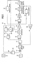
- Bei dem aus Figur 4 ersichtlichen Strukturmodell eines Steuerungsalgorithmus 25 der Kupplungslagesteuerung werden einem ersten Multiplexer 26 über schematisch angedeutete Signaleingänge (1) bis (4) der Positionssollwert x_soll und dessen Ableitungen dx_soll, ddx_soll und dddx_soll eingegeben. In einem mit dem Ausgang des Multiplexers 26 verbundenen Programmblock Steuerung KUPPLUNGSLAGE 29 wird aus diesen Eingangssignalen ein Steuersignal 30, das die Kupplungslage festlegt, berechnet und an einen Umschalter 31 gelegt.
- Über weitere Signaleingänge 32 mit den Bezeichnungen (5) und (6) werden einem zweiten Multiplexer 34 der Drucksollwert p_soll und dessen Ableitung dp_soll eingegeben. In einem mit dem Ausgang des Multiplexers 34 verbundenen Programmblock 35 Steuerung DRUCKAUFBAU wird aus diesen Eingangssignalen ein Steuersignal 36, das den Druckaufbau in dem Stellzylinder 22 steuert, berechnet und an den Umschalter 31 gelegt. In den Programmblöcken 29 und 35 sind Programme abgelegt, die mit einem im Handel unter der Bezeichnung MATLAB erhältlichen Programmentwicklungswerkzeug("Software tool") erstellt worden sind und mit denen die Kupplungslage beziehungsweise der Druckaufbau gesteuert werden.
- Durch ein über einen Eingang (7) eingegebenes Betriebsmodus-Signal 37 schaltet der Umschalter 31 entweder das Signal 30 oder das Signal 36 auf seinen Ausgang durch. Dem jeweiligen Signal wird in einem Addierglied 38 ein Dither-Signal, das in einem Block 39 erzeugt wird, addiert, um Magnethysterese und Reibungseffekte im Ventil zu reduzieren. In einer Begrenzerschaltung wird die Signalamplitude beidseitig begrenzt und mit einem Zeitglied 41 wird eine durch die Funktionsauswertung verursachte Totzeit dargestellt. An einem Signalausgang 42 wird schließlich ein das Stellsignal darstellender Strom I ausgegeben.
- Das Streckenmodell 44 des Kupplungsbetätigungssystems ist in Figur 5 bei geöffnetem Steuerdurchlass P-A dargestellt. Es weist folgende Blöcke auf: einen Eingang 45, an dem der Systemdruck p_P anliegt (Anmerkung: die Größen pP, p P und p_P usw. sind gleichbedeutend, die unterschiedliche Schreibweise beruht auf unterschiedlichen Notationen in verschiedenen verwendeten Programmen) Von dort gelangt p_P zu dem Pluseingang eines Addierers 46, an dessen Minuseingang der Zylinder- oder Arbeitsdruck pA anliegt. Sein Ausgangssignal wird in einem Multiplexer 47 mit dem Spulenstrom I, der an einem Eingang 48 anliegt, zu einem Vektorsignal zusammengefasst.
- Der Ausgang des Multiplexers 47 ist mit einem Block 50 verbunden, der den Volumenstrom Q berechnet und ihn auf den Pluseingang eines Addierers 51 mit einem negierten Eingang gibt. Auf dessen negierten oder Minuseingang wird eine Volumenänderung ΔV gegeben und die sich ergebende Differenz wird in einem Multiplizierer 52 mit dem Ausgangssignal eines Dividiergliedes 54 multipliziert. Auf den Nennereingang des Dividierers 54 gelangt der Elastizitätsmodul E_Oel der Gesamtanordnung, einschließlich des Hydrauliköls, der in einem Block 55 abhängig von dem Zylinderdruck ermittelt wird. An den Zählereingang des Dividiergliedes 54 wird das in einem Block 56 abhängig von der Zylinderposition ermittelte Volumen V des hydraulischen Kupplungsbetätigungssystems einschließlich des Stell-Zylinders 22 gelegt.
- In einem Integrierglied 58 wird aus dem Ausgangssignal des Multiplizierers 52 der Zylinderdruck berechnet und an den Minuseingang des Addierers 46 sowie an den Eingang eines als Multiplizierer dienenden Verstärkers 59 gelegt. In diesem wird er mit der wirksamen Zylinderfläche A multipliziert. Das Ergebnis gelangt an einen Eingang eines Addierers 60, an dessen zweiten Eingang die auf den Stellzylinder einwirkende Federkraft F Feder gelangt, die in einem Block 62 aus der Zylinderposition berechnet wird. An einen dritten Eingang des Addierers 60 wird die in dem Stellzylinder auftretende Reibkraft F Reih gelegt, die in einem Block 63 ermittelt wird.
- Das Ausgangssignal des Addierers 60 gelangt zu einem Verstärker 64, und wird dort durch die bewegte Masse m_z dividiert. In einem Integrierglied 66 wird das Ergebnis der Division integriert und damit die Zylindergeschwindigkeit berechnet. Durch nochmalige Integration in einem Integrierglied 67 wird die Zylinderposition berechnet und auf den Eingang des Blocks 62 und des Blocks 56 gelegt. Die Zylindergeschwindigkeit wird einerseits auf den Eingang des Blocks 63 und andererseits an den Eingang eines Verstärkers 68 gelegt, in dem sie mit der wirksamen Zylinderfläche A_z multipliziert wird. Das Ergebnis der Multiplikation ist eine Volumenänderung ΔV im Zylinder, die auf einen Minuseingang des Addierers 51 gelegt wird.
- Die Strecke 44 (Figur 5) der Kupplungsbetätigung lässt sich durch folgende drei Differentialgleichungen beschreiben:


- Darin sind:
- x z
- die Position der Kupplung oder des Stellzylinders
- v z
- die Geschwindigkeit der Kupplung oder des Stellzylinders
- m z
- die bewegte Masse
- A z
- die wirksame Fläche des Stellzylinders
- p,
- ṗ der Druck im Stellzylinder und dessen Ableitung
- E öl
- den druckabhängigen Elastizitätsmodul der Gesamtanordnung
- V
- das Volumen der Gesamtanordnung
- Q
- der Volumenstrom von Hydraulikflüssigkeit
- x v
- die Position des Ventilschiebers und
- Δ p
- eine Druckdifferenz, die gegeben ist durch:
- Der Volumenstrom Q ist eine Funktion dieser Druckdifferenz und der Ventilschieberposition xv.
- Die Ventilschieberposition x v und die Ventilschiebergeschwindigkeit vv berechnen sich wie folgt


- Für die tatsächliche Steuerung des Kupplungslagesystems wird das vereinfachte Streckenmodell 44 (Figur 5) verwendet. Dabei wird die hochfrequente Dynamik des Ventilschiebers vernachlässigt und die Ventilschieberposition durch eine algebraische Gleichung der Form


- Diese Funktion, die den stationären Durchfluss Q in Abhängigkeit der beiden Größen I und Δp darstellt, wird numerisch ermittelt. Sie ist aus Figur 6 ersichtlich.
- Es ergeben sich somit folgende Differentialgleichungen:


- Eine Berechnung der einzelnen Blöcke von Figur 5 erfolgt in einem Ausführungsbeispiel gemäß nachstehender Gesetzmäßigkeiten.
- Befindet sich der Stellzylinder am Anschlag, so gelten folgende Differentialgleichungen:


- Die Kupplungslage wird, da die Strecke nichtlinear ist, nichtlinear wie folgt gesteuert. Um die Schreibweise zu vereinfachen werden die Indizes z (für Zylinder) und Öl im folgenden weg gelassen. Man erhält die Darstellung


- Mit y=x erhält man die Zustandsgrößen


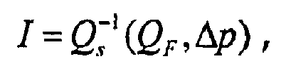
- Da der Volumenstrom Q=Q s (I,Δp) eine bezüglich I im interessierenden Definitionsbereich monoton steigende Funktion ist, existiert eine inverse Funktion

- Die Eingangsgröße I lässt sich als Funktion der Ausgangsgröße y und deren zeitlichen Ableitungen darstellen



- Dieses Ergebnis wird für eine nichtlineare Steuerung der Kupplungsbetätigung mit einem Sollstrom I d verwendet:

- Um den Steueralgorithmus zu vereinfachen, können auch höhere Ableitungen in dieser Gleichung vernachlässigt werden, zum Beispiel wie folgt

- Der Druckaufbau in dem Stellzylinder 22 des Kupplungsbetätigungssystems wird wie folgt gesteuert.
- Befindet sich der Stellzylinder an einem Anschlag, gilt für den Druck in ihm

- Hieraus ergibt sich:

- Durch Einsetzen der Sollwerte p d und ṗ d erhält man mit der inversen Funktion


- Mit diesem Steuerstrom I wird der Arbeitsdruck p A im Stellzylinder gesteuert.
- Die Steuerung der Kupplung erfolgt mit einer inversen Strecke, die durch Invertieren der anhand von Figur 5 dargestellten Strecke gewonnen wird.
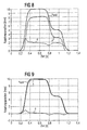
- In Figur 8 sind der Sollwert x soll und der Istwert x z der Kupplungsposition bei einer Steuerung ohne eine Druckaufbauphase aufgetragen. Der Sollverlauf ist entsprechend einem typischen Kuppelvorgang vorgegeben. Außerdem ist der auftretende Fehler e dargestellt. Bei dem Auskuppelvorgang (links in der Figur) beträgt der maximale Fehler e etwa 3 mm, bei dem darauf folgenden Einkuppelvorgang (rechts) über 1 mm.
- In Figur 9 sind der Sollwert x soll und der Istwert x z der Kupplungsposition bei einer erfindungsgemäßen Steuerung mit einer Druckaufbauphase von 0 sec bis 0,1 sec aufgetragen. Deutlich erkennbar ist der hier erheblich geringere Fehler e von etwa 1 mm beim Auskuppeln und etwa 0,5 mm beim Einkuppeln. Dies stellt eine erheblich verbesserte Betätigung der Kupplung dar, die zu einem größeren Fahrkomfort und einem geringeren Verschleiß führt.
- Ein aus Figur 10 ersichtliches Programm zum Steuern einer automatischen Kraftfahrzeugkupplung weist folgende Schritte auf:
- Start:
- sobald von der elektronischen Steuerung 8 (Figur 1) ein Schaltvorgang eingeleitet wird, werden von ihr in einem Schritt
- S1:
- eine Kupplungssollposistion x_soll beziehungsweise ein Solldruck p_soll vorgegeben. Dann erfolgt in einem Schritt
- S2:
- eine Abfrage, ob der Stellzylinder der Kupplung an einem Anschlag anliegt. Falls ja, wird in einem Schritt
- S3:
- eine Steuerung eines Druckaufbau in dem Stellzylinder 22 der Kupplung. Falls nein, erfolgt in einem Schritt
- S4:
- eine Steuerung der Kupplungslage und danach in einem Schritt
- S5:
- eine Aufschaltung eines Dither-Signals und eine Signalbegrenzung. Im Anschluss an S4 oder S5 wird in einem Schritt
- S6
- eine Stellgröße zum Beispiel als Eingangsstrom für das Ventil 21 berechnet. Damit ist ein Abtastschritt des Kupplungsvorgangs erfolgreich beendet, ohne dass ein Signal eines Positionssensors ausgewertet worden wäre. Der Abtastschritt wird zyklisch wiederholt (zum Beispiel alle 4 ms). - Schließlich wird
- S7:
- der Stellzylinder 22 betätigt und dabei die Kupplung 23 in Richtung ihrer Ausrückposition bewegt wird. Damit ist ein Betätigungsvorgang der Kupplung (etwa nach 30 ms) beendet.

wobei A für den Arbeitsdruck und das mit ihm gefüllte Volumen, P für den Systemdruck und das mit ihm gefüllte Volumen und T für den (Vorrats-)Tank und den Druck in diesem stehen.
Claims (8)
- Verfahren zum Steuern einer automatischen Kraftfahrzeugkupplung mit einem Stellglied zum Betätigen der Kupplung und einem elektromagnetisch betätigten Ventil, mit dessen Spulenstrom der Druck in dem Stellglied und damit die Position der Kupplung festgelegt wird,
dadurch gekennzeichnet,- dass anhand eines regeltechnischen Modells einer zu steuernden nicht linearen Strecke ein inverses Streckenmodell erstellt wird, und- dass mit dem inversen Streckenmodell der Spulenstrom des Ventils gesteuert wird. - Verfahren nach Anspruch 1, dadurch gekennzeichnet, dass bei an einem Anschlag anliegenden Stellzylinder für die Kupplung der Druck in diesem Stellzylinder aufgebaut und anhand eines ermittelten Druckwerts ein Steuersignal für die Position der Kupplung erzeugt wird.
- Verfahren nach Anspruch 1, dadurch gekennzeichnet, dass der Druck in dem Stellglied gemäß einer vorgegebenen Solltrajektorie derart gesteuert wird, daß am Ende einer Druckaufbauphase die durch den Druck erzeugte Kraft gleich einer Federvorspannung ist, gegen die sich das Stellglied zu Beginn eines Kupplungsvorgangs an einem Anschlag befindet.
- Verfahren nach Anspruch 3, dadurch gekennzeichnet, dass der als Stellsignal dienende Spulenstrom in einer Kupplungslagephase nach Beendigung der Druckaufbauphase aus einer Solltrajektorie der Position der Kupplung und deren zeitlichen Ableitungen berechnet wird.
- Verfahren nach Anspruch 4, dadurch gekennzeichnet, dass durch ein den Betriebsmodus festlegendes Signal zwischen der Druckaufbauphase und der Kupplungslagephase umgeschaltet wird.
- Verfahren nach Anspruch 4, dadurch gekennzeichnet, dass zu dem Stellsignal in der Druckaufbauphase und in der Kupplungslagephase ein Dither-Signal addiert wird, um eine Magnethysterese und Reibungseffekte im Ventil zu verringern.
- Verfahren nach Anspruch 1, dadurch gekennzeichnet, dass ein Volumenstrom, durch den das Ventil betätigt wird, berechnet wird nach einer Beziehung


worin:A die wirksame Fläche des Stellzylinders,E der Elastizitätsmodul der Gesamtanordnung, einschließlich des Hydrauliköls,m die bewegte Masse undy die Ausgangsgröße der Steuerung, zum Beispiel die Kupplungspositionsind. - Verfahren nach Anspruch 7, dadurch gekennzeichnet, dass der Steuerstrom (I) in der Druckaufbauphase nach der Beziehung


Applications Claiming Priority (3)
| Application Number | Priority Date | Filing Date | Title |
|---|---|---|---|
| DE10046108 | 2000-09-18 | ||
| DE10046108 | 2000-09-18 | ||
| PCT/DE2001/003548 WO2002025130A1 (de) | 2000-09-18 | 2001-09-14 | Verfahren zum steuern einer automatischen kraftfahrzeugkupplung |
Publications (2)
| Publication Number | Publication Date |
|---|---|
| EP1319138A1 EP1319138A1 (de) | 2003-06-18 |
| EP1319138B1 true EP1319138B1 (de) | 2006-03-01 |
Family
ID=7656627
Family Applications (1)
| Application Number | Title | Priority Date | Filing Date |
|---|---|---|---|
| EP01978144A Expired - Lifetime EP1319138B1 (de) | 2000-09-18 | 2001-09-14 | Verfahren zum steuern einer automatischen kraftfahrzeugkupplung |
Country Status (3)
| Country | Link |
|---|---|
| EP (1) | EP1319138B1 (de) |
| DE (1) | DE50109102D1 (de) |
| WO (1) | WO2002025130A1 (de) |
Cited By (1)
| Publication number | Priority date | Publication date | Assignee | Title |
|---|---|---|---|---|
| CN101509529B (zh) * | 2008-02-14 | 2013-05-08 | 格特拉格传动机构和齿轮工厂赫尔曼·哈根迈尔有限公司&两合公司 | 用于致动车辆离合器的方法 |
Families Citing this family (5)
| Publication number | Priority date | Publication date | Assignee | Title |
|---|---|---|---|---|
| DE10226670B4 (de) * | 2002-06-14 | 2004-09-02 | Siemens Ag | Regeleinrichtung und -verfahren |
| DE50303114D1 (de) * | 2003-07-26 | 2006-06-01 | Zf Sachs Ag | Hydraulisch betätigbare Lamellenkupplung |
| DE102007022792A1 (de) * | 2007-05-11 | 2008-11-20 | Knorr-Bremse Systeme für Nutzfahrzeuge GmbH | Kupplungsstellvorrichtung für ein manuelles Schaltgetriebe eines Fahrzeugs und entsprechendes Steuerungsverfahren |
| EP2233766B1 (de) * | 2009-03-27 | 2012-06-27 | Hoerbiger Drivetrain Mechatronics B.V.B.A. | Vorrichtung zur Steuerung des Kupplungsdrucks |
| DE102024003558A1 (de) * | 2024-10-29 | 2026-04-30 | Hydac Fluidtechnik Gmbh | Verfahren zum Ermitteln eines Volumenstroms |
Family Cites Families (5)
| Publication number | Priority date | Publication date | Assignee | Title |
|---|---|---|---|---|
| DE3831449A1 (de) | 1988-09-16 | 1990-03-22 | Man Nutzfahrzeuge Ag | Elektronisches betriebssteuersystem fuer einen kraftfahrzeug-antriebsstrang |
| DE19504847B4 (de) * | 1994-02-23 | 2006-04-27 | Luk Gs Verwaltungs Kg | Überwachungsverfahren für ein Drehmoment-Übertragungssystem eines Kraftfahrzeugs |
| DE4434111A1 (de) | 1994-09-23 | 1996-03-28 | Kongsberg Automotive Technolog | Steuerung für eine automatisch betätigte Kupplung |
| DE19826747A1 (de) * | 1997-07-14 | 1999-01-21 | Luk Getriebe Systeme Gmbh | Getriebe |
| EP1058019B1 (de) * | 1999-06-04 | 2003-01-08 | Ford Global Technologies, Inc. | Steuerung für eine fluidbetätigte Kupplung |
-
2001
- 2001-09-14 WO PCT/DE2001/003548 patent/WO2002025130A1/de not_active Ceased
- 2001-09-14 DE DE50109102T patent/DE50109102D1/de not_active Expired - Lifetime
- 2001-09-14 EP EP01978144A patent/EP1319138B1/de not_active Expired - Lifetime
Cited By (1)
| Publication number | Priority date | Publication date | Assignee | Title |
|---|---|---|---|---|
| CN101509529B (zh) * | 2008-02-14 | 2013-05-08 | 格特拉格传动机构和齿轮工厂赫尔曼·哈根迈尔有限公司&两合公司 | 用于致动车辆离合器的方法 |
Also Published As
| Publication number | Publication date |
|---|---|
| DE50109102D1 (de) | 2006-04-27 |
| EP1319138A1 (de) | 2003-06-18 |
| WO2002025130A1 (de) | 2002-03-28 |
Similar Documents
| Publication | Publication Date | Title |
|---|---|---|
| EP1319139B1 (de) | Verfahren zum steuern einer automatischen kraftfahrzeugkupplung | |
| DE102012021211B4 (de) | Verfahren zum Ermitteln eines Einstellparameters in einer hydraulischen Aktuatoranordnung für einen Kraftfahrzeugantriebsstrang und Verfahren zum Betätigen einer Reibkupplung eines Kraftfahrzeugantriebsstranges | |
| DE60132159T2 (de) | Vorrichtung zur Bestimmung des Kupplungszustands in einem Hybridfahrzeug und ihre Verwendung zur Steurung eines Gangschaltgetriebes | |
| EP2386774B1 (de) | Verfahren zur Ansteuerung einer Reibkupplung | |
| EP1858740B1 (de) | Verfahren und vorrichtung zur steuerung eines kraftfahrzeug-antriebsstranges | |
| DE10343096B4 (de) | Verfahren und Vorrichtung zum Vermeiden von durch Axialverschiebungen zwischen einer Kupplungseingangswelle und einer Kupplungsausgangswelle bedingten Referenzpositionsverschiebungen einer von einem Aktor betätigten Kupplung | |
| DE102008032245B4 (de) | Verfahren zum Ansteuern einer Kupplungsanordnung | |
| DE102013210357A1 (de) | Verfahren zum Bestimmen eines Verschleißes einer Kupplung | |
| EP3464924B1 (de) | Fahrzeug sowie verfahren zum betreiben einer kupplung als anfahrelement | |
| EP1324906A1 (de) | Verfahren und regelsystem zur ansteuerung eines elektronisch regelbaren bremsbetätigungssystems | |
| DE102019204402A1 (de) | Bestimmung eines Steuerstroms für ein Stetigventil | |
| DE10138725A1 (de) | Steuereinrichtung | |
| DE60119447T2 (de) | Fahrzeugkupplungssteuerungssystem | |
| EP1257746B1 (de) | Automatisch betätigte kraftfahrzeug-kupplung und verfahren zum steuern einer kraftfahrzeug-kupplung | |
| EP2046616B1 (de) | Verfahren zur überwachung eines anfahrvorganges eines kraftfahrzeugs | |
| DE10137581C1 (de) | Verfahren zum Steuern einer automatischen Kraftfahrzeugkupplung | |
| EP1437520A2 (de) | Verfahren zum Steuern einer automatisch betätigten Kupplung | |
| WO2002025130A1 (de) | Verfahren zum steuern einer automatischen kraftfahrzeugkupplung | |
| DE10046106C1 (de) | Verfahren zum Regeln einer automatischen Kraftfahrzeugkupplung | |
| DE10127766A1 (de) | Verfahren und Vorrichtung zum Kompensieren des Einflusses der Drehzahl auf die Kennlinie einer Kupplung | |
| EP1320695B1 (de) | Verfahren zum regeln einer automatischen kraftfahrzeugkupplung | |
| DE102016218428A1 (de) | Verfahren zur Steuerung einer Reibungskupplung | |
| DE102015226539A1 (de) | "Verfahren zur Steuerung und/oder Regelung einer nasslaufenden Kupplung eines Kraftfahrzeugs" | |
| DE102008020578A1 (de) | Verfahren zum Steuern einer Kupplungsanordnung | |
| DE69815727T2 (de) | Verfahren und Gerät zur Steuerung der Kupplung eines Fahrzeugs |
Legal Events
| Date | Code | Title | Description |
|---|---|---|---|
| PUAI | Public reference made under article 153(3) epc to a published international application that has entered the european phase |
Free format text: ORIGINAL CODE: 0009012 |
|
| 17P | Request for examination filed |
Effective date: 20030228 |
|
| AK | Designated contracting states |
Designated state(s): AT BE CH CY DE DK ES FI FR GB GR IE IT LI LU MC NL PT SE TR |
|
| RIN1 | Information on inventor provided before grant (corrected) |
Inventor name: MICHAU, PETER Inventor name: BAMBERGER, JOACHIM Inventor name: HORN, JOACHIM Inventor name: NOCK, ERNST |
|
| RBV | Designated contracting states (corrected) |
Designated state(s): DE FR |
|
| GRAP | Despatch of communication of intention to grant a patent |
Free format text: ORIGINAL CODE: EPIDOSNIGR1 |
|
| GRAS | Grant fee paid |
Free format text: ORIGINAL CODE: EPIDOSNIGR3 |
|
| GRAA | (expected) grant |
Free format text: ORIGINAL CODE: 0009210 |
|
| AK | Designated contracting states |
Kind code of ref document: B1 Designated state(s): DE FR |
|
| REF | Corresponds to: |
Ref document number: 50109102 Country of ref document: DE Date of ref document: 20060427 Kind code of ref document: P |
|
| ET | Fr: translation filed | ||
| PLBE | No opposition filed within time limit |
Free format text: ORIGINAL CODE: 0009261 |
|
| STAA | Information on the status of an ep patent application or granted ep patent |
Free format text: STATUS: NO OPPOSITION FILED WITHIN TIME LIMIT |
|
| 26N | No opposition filed |
Effective date: 20061204 |
|
| REG | Reference to a national code |
Ref country code: FR Ref legal event code: TP |
|
| REG | Reference to a national code |
Ref country code: FR Ref legal event code: PLFP Year of fee payment: 16 |
|
| REG | Reference to a national code |
Ref country code: FR Ref legal event code: PLFP Year of fee payment: 17 |
|
| REG | Reference to a national code |
Ref country code: FR Ref legal event code: PLFP Year of fee payment: 18 |
|
| PGFP | Annual fee paid to national office [announced via postgrant information from national office to epo] |
Ref country code: FR Payment date: 20180924 Year of fee payment: 18 |
|
| PGFP | Annual fee paid to national office [announced via postgrant information from national office to epo] |
Ref country code: DE Payment date: 20180930 Year of fee payment: 18 |
|
| REG | Reference to a national code |
Ref country code: DE Ref legal event code: R119 Ref document number: 50109102 Country of ref document: DE |
|
| PG25 | Lapsed in a contracting state [announced via postgrant information from national office to epo] |
Ref country code: DE Free format text: LAPSE BECAUSE OF NON-PAYMENT OF DUE FEES Effective date: 20200401 |
|
| PG25 | Lapsed in a contracting state [announced via postgrant information from national office to epo] |
Ref country code: FR Free format text: LAPSE BECAUSE OF NON-PAYMENT OF DUE FEES Effective date: 20190930 |