EP1318901B1 - Thermally regulated closed mixer - Google Patents
Thermally regulated closed mixer Download PDFInfo
- Publication number
- EP1318901B1 EP1318901B1 EP01971967A EP01971967A EP1318901B1 EP 1318901 B1 EP1318901 B1 EP 1318901B1 EP 01971967 A EP01971967 A EP 01971967A EP 01971967 A EP01971967 A EP 01971967A EP 1318901 B1 EP1318901 B1 EP 1318901B1
- Authority
- EP
- European Patent Office
- Prior art keywords
- mixer
- set point
- body temperature
- mixer body
- temperature
- Prior art date
- Legal status (The legal status is an assumption and is not a legal conclusion. Google has not performed a legal analysis and makes no representation as to the accuracy of the status listed.)
- Expired - Lifetime
Links
Images

Classifications
-
- B—PERFORMING OPERATIONS; TRANSPORTING
- B29—WORKING OF PLASTICS; WORKING OF SUBSTANCES IN A PLASTIC STATE IN GENERAL
- B29B—PREPARATION OR PRETREATMENT OF THE MATERIAL TO BE SHAPED; MAKING GRANULES OR PREFORMS; RECOVERY OF PLASTICS OR OTHER CONSTITUENTS OF WASTE MATERIAL CONTAINING PLASTICS
- B29B7/00—Mixing; Kneading
- B29B7/02—Mixing; Kneading non-continuous, with mechanical mixing or kneading devices, i.e. batch type
- B29B7/22—Component parts, details or accessories; Auxiliary operations
- B29B7/28—Component parts, details or accessories; Auxiliary operations for measuring, controlling or regulating, e.g. viscosity control
- B29B7/286—Component parts, details or accessories; Auxiliary operations for measuring, controlling or regulating, e.g. viscosity control measuring properties of the mixture, e.g. temperature, density
-
- B—PERFORMING OPERATIONS; TRANSPORTING
- B29—WORKING OF PLASTICS; WORKING OF SUBSTANCES IN A PLASTIC STATE IN GENERAL
- B29B—PREPARATION OR PRETREATMENT OF THE MATERIAL TO BE SHAPED; MAKING GRANULES OR PREFORMS; RECOVERY OF PLASTICS OR OTHER CONSTITUENTS OF WASTE MATERIAL CONTAINING PLASTICS
- B29B7/00—Mixing; Kneading
- B29B7/02—Mixing; Kneading non-continuous, with mechanical mixing or kneading devices, i.e. batch type
- B29B7/22—Component parts, details or accessories; Auxiliary operations
- B29B7/28—Component parts, details or accessories; Auxiliary operations for measuring, controlling or regulating, e.g. viscosity control
-
- B—PERFORMING OPERATIONS; TRANSPORTING
- B29—WORKING OF PLASTICS; WORKING OF SUBSTANCES IN A PLASTIC STATE IN GENERAL
- B29B—PREPARATION OR PRETREATMENT OF THE MATERIAL TO BE SHAPED; MAKING GRANULES OR PREFORMS; RECOVERY OF PLASTICS OR OTHER CONSTITUENTS OF WASTE MATERIAL CONTAINING PLASTICS
- B29B7/00—Mixing; Kneading
- B29B7/80—Component parts, details or accessories; Auxiliary operations
- B29B7/82—Heating or cooling
- B29B7/823—Temperature control
Definitions
- the present invention relates to a process for producing a compound in a closed batch mixer, and more particularly to a method for setting the thermal parameters of the body mixer before and during the processing of this compound.
- closed batch mixer it is intended an apparatus comprising a closed container enfolding a pair of rotors revolving in opposite directions to mix the various ingredients of a compound.
- the apparatus further comprises a cylinder located at the top of the container, whose piston, commonly known as ram, is driven either upwards to open the container and allow the introduction of the ingredients of the compound from suitable filling hoppers or downwards to exert a pressure on the material being processed above the pair of rotors.
- a device placed at the bottom of the container allows the compound to be emptied out at the end of the processing cycle, via the opening of a suitable outlet.
- Apparatus of the type mentioned above are, for example, of the "Banbury®” type, processing the material by means of a pair of tangential rotors, while other apparatus, known under the name "Intermix®”, process the material by means of a pair of intermeshing rotors.
- batchwise manner production it is intended the production of defined quantities (batch) of compound in a discontinuous manner, each batch being processed starting from the ingredients till to complete compound dumping.
- the material being processed during the various phases will be referred to as the compound.
- a compound which can be prepared according to the invention is a compound, for example, of the type comprising an unsaturated-chain polymer base, in case crosslinked with sulphur, which is added to at least one silica filler and a silica-binding agent containing at least one sulphur atom.
- the silica filler is a reinforcing agent based on silicon dioxide (silica), silicates or mixtures thereof, with a surface area, measured by the BET method, of between 80 and 220 m 2 /g, preferably between 160 and 180 m 2 /g.
- the silica-binding agent it is intended, for example, a silane containing sulphur, such as bis(3-tnethoxysilylpropyl)-tetrasulfide.
- the quality of a compound produced by batch mixer processes is attained by first producing a test compound and checking the properties of a number of samples, particularly after vulcanisation. Then, if one or more of these properties do not fit the set ranges, it takes to correct the values of the various process parameters as and when necessary by trial and error, until the desired result is achieved.
- the problem to be solved is that of ensuring the reproducibility of the properties of the approved compound, for all the identical compounds subsequently produced, batch after batch.
- SU-A-1318420 (in the name of Kiev Poly) teaches "to maintain the pressure of a heating carrier circulating in a mixer apparatus at a given temperature for increasing the thermal stabilisation of the working surfaces of the rotors and the quality of the final product".
- GB-B-2084035 discloses the monitoring of the working material temperature and its comparison with the power consumption of the mixer motor for achieving better characteristics of the working material in a shorter time.
- EP-B-244121 (in the name of Farrel Bndge Ltd.) relates to a process for mixing a polymeric composition wherein the control of the mixer temperature is associated to the adjustment of the speed rotors and/or of the pressure applied by the ram. This should result in a completely homogeneous mixture with minimum of operator attention.
- WO 99/24230 discloses a system for controlling the mixing of polymeric material and additive for providing quality products and batch-to-batch product uniformity.
- the temperature of the batch is controlled and corrected within a predetermined temperature profile through the adjustment of at least one of the rotor speed and the ram pressure.
- the mixer is preferably equipped with an automated system programmed to store various mixing cycle parameters such as, inter alia, the pre-set mixer wall temperature. It is underlined that the time for starting the claimed control system depends on the type of material to be compounded.
- the batch temperature is not homogeneous at the start of the mixing cycle when stiff or highly viscous components, such as natural rubber, are employed
- the control start time would be delayed until a time after the start of the mixing cycle.
- the control could be started at the beginning of the mixing cycle.
- first batches are produced under transient conditions (temperature, time, energy) which reach their normal operating values after some working cycles.
- This irregularity herein named as first batch effect, affects the duration of the mixing cycle and the uniformity of the compound.
- the first batch effect involves generally up to the first three or four batches from the beginning of the process, depending on the room temperature, kind of materials and process temperature.
- the present invention is based on the perception of the problem of the first batch effect as related to the working temperature of the body mixer and its thermal hysteresis.
- continuous real time measurement it is intended a measurement effected at intervals preferably no longer than 1 second.
- the present invention relates to a method for minimising the first batch effect in the mixing of a compound in a closed batch mixer, including the phases of
- the switching from Set Point 2 to Set Point 1 is excluded when the mixer cycle is running.
- the measure of the mixer body temperature is carried out by providing at least two sensors on the external surface of the body mixer.
- a mixer body temperature is considered the average value of the temperatures measured by the sensors.
- the above said predetermined temperature values are stored and managed by a computerised control system.
- a specific set of temperature values shall be predetermined and controlled.
- the Set Point 1 and the Set Point 2 are determined as defined temperatures of a thermal regulation fluid, for example, water.
- the Break Point A is said minimum temperature of the mixer body plus the thermal hysteresis of the mixer body.
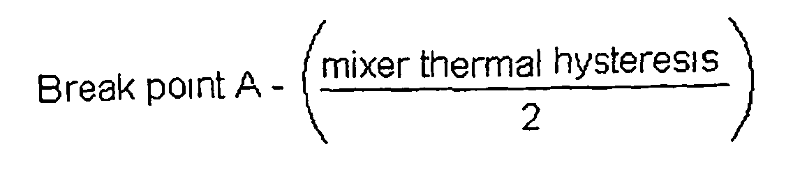
- the Break Point B is the result of the following equation:
- the present invention relates to a process for mixing a compound in a closed batch mixer comprising
- the method and the process of the present invention may be applied irrespective on the kind of compound to be processed. Particularly, the method and process of the invention give most favourable results when applied to silica-filled compounds.
- the uniformity of the final compound is improved also for the first batches, in such as the cycle time and the quantity of energy employed in said first batches conform to the average values of the subsequent batches.
- the following mixing cycle description and time calculation is referred to masterbatch batch containing the ingredients of the above list without the asterisk.
- the ingredients marked by an asterisk are added in the remill, and those marked by two asterisks are added in the final stage.
- a mixing cycle was started by predetermining the following temperature values:
- the duration of the first batch mixing cycles was substantially equal to that of the subsequent batch mixing cycles, as set forth in the following Table 1 refernng to mixing cycles carried out according to the present invention.
- Table 2 refers to the mixing cycles carried out without the control system of the invention.
- the duration of the mixing cycle of the first 3 batches of each lot was compared with that of randomly selected subsequent batches (18 and 26).
- Batch Duration of the mixing cycle (sec) 1 257 2 257 3 254 18 255 26 256
- the rheometric characteristics for each batch were measured according to known techniques (Monsanto MDR rheometer; curing condition: 185° for 180 seconds).
- the standard deviations set forth in table 3 for the first batches prepared according to the present invention demonstrate that the values relating to such batches are less scattered around the average value (central value) than those of the first batches of reference. This means that the rheometric characteristic of the first batches produced according to the present invention are more uniform to the central value of the entire production.
Landscapes
- Engineering & Computer Science (AREA)
- Mechanical Engineering (AREA)
- Processing And Handling Of Plastics And Other Materials For Molding In General (AREA)
- Apparatuses For Bulk Treatment Of Fruits And Vegetables And Apparatuses For Preparing Feeds (AREA)
Description
- predetermining a minimum mixer body temperature value for starting the mixing cycle;
- predetermining a mixer thermal regulation system pre-heating
temperature as Set
Point 1; - predetermining a mixer thermal regulation system working temperature as Set Point 2;
- predetermining the mixer body thermal hysteresis;
- predetermining a mixer body temperature Break Point A for switching
the mixer thermal regulation system from
Set Point 1 to Set Point 2; - predetermining a mixer body temperature Break Point B for switching
the mixer thermal regulation system from Set Point 2 to
Set Point 1; - directly measuring, in a continuous real-time, the mixer body temperature;
- comparing the mixer body temperature to the predetermined Break Point temperatures A and B; and
- switching the mixer thermal regulation system from one Set Point to the other as a result of the above comparison.
| Natural rubber | 8.00 |
| Polybutadiene | 20.00 |
| SBR ("solution") | 72.00 |
| Extender oil | 5.00 |
| Silica | 63.00 |
| Stearic acid | 2.00 |
| Zinc oxide* | 2.50 |
| Processing aid | 2.00 |
| Silane (50% predispersed) | 10.00 |
| Wax * | 1.00 |
| TMQ - type amine anti-fatigue* | 1.00 |
| 6PPD - type amine anti-ageing* | 2.00 |
| Sulphur** | 1.20 |
| CBS - type sulfenamide accelerating** | 2 00 |
| Diphenylguanidine accelerating (80% active)** | 0.80 |
- minimum mixer body temperature = 35°C
- mixer body thermal hysteresis = 10°
-
Set Point 1 = 55°C - Set Point 2 = 30°C
- Break Point A = 45°C
- Break Point B = 40°C
| Batch | Duration of the mixing cycle (sec) |
| 1 | 257 |
| 2 | 257 |
| 3 | 254 |
| 18 | 255 |
| 26 | 256 |
| Batch | Duration of the mixing cycle (sec) |
| 1 | 335 |
| 2 | 308 |
| 3 | 289 |
| 18 | 274 |
| 26 | 269 |
| Rheometric Characteristics | Central Value | Standard deviation (1σ) on the first 5 batches according to the invention | Standard deviation (1σ) on the first 5 comparison reference batches |
| ML (dNm) | 3.7 | 0.055 | 0.084 |
| MH (dNm) | 12.2 | 0.167 | 0.421 |
| t30 (min) | 78 | 0 | 2.168 |
| t60 (min) | 101 | 0.837 | 2.966 |
Claims (19)
- Method for mixing a compound in a closed batch mixer, including the phases ofpredetermining a minimum mixer body temperature value for starting the mixing cycle;predetermining a mixer thermal regulation system pre-heating temperature as Set Point 1;predetermining a mixer thermal regulation system working temperature as Set Point 2;predetermining the mixer body thermal hysteresis;predetermining a mixer body temperature Break Point A for switching the mixer thermal regulation system from Set Point 1 to Set Point 2;predetermining a mixer body temperature Break Point B for switching the mixer thermal regulation system from Set Point 2 to Set Point 1;directly measuring, in a continuous real-time, the mixer body temperature,comparing the mixer body temperature to the predetermined Break Point temperatures A and B; andswitching the mixer thermal regulation system from one Set Point to the other as a result of the above comparison.
- Method according to claim 1 wherein the switching from Set Point 2 to Set Point 1 is excluded when the mixer cycle is running.
- Method according to claim 1 wherein the measure of the mixer body temperature is carried out by providing at least two sensors on the external surface of the body mixer.
- Method according to claim 1 wherein the average value of the temperatures measured by the sensors is considered as a mixer body temperature.
- Method according to claim 1 wherein the predetermined temperature values are stored and managed by a computerised control system.
- Method according to claim 1 wherein Set Point 1 and Set Point 2 are determined as defined temperatures of a thermal regulation fluid.
- Method according to claim 6 wherein the thermal regulation fluid is water.
- Method according to claim 1 wherein the Break Point A is said minimum temperature of the mixer body plus the thermal hysteresis of the mixer body.
- Method according to claim 1 wherein the Break Point B is the result of the following equation:

- Process for mixing a compound in a closed batch mixer comprisinga) predetermining a minimum mixer body temperature value for starting the mixing cycle;b) predetermining a mixer thermal regulation system pre-heating temperature as Set Point 1;c) predetermining a mixer thermal regulation system working temperature as Set Point 2;d) predetermining the mixer body thermal hysteresis;e) predetermining a mixer body temperature Break Point A for switching the mixer thermal regulation system from Set Point 1 to Set Point 2;f) predetermining a mixer body temperature Break Point B for switching the mixer thermal regulation system from Set Point 2 to Set Point 1;g) directly measuring, in a continuous real-time, the mixer body temperature;h) comparing the mixer body temperature to the predetermined Break Point temperatures A and B;i) switching the mixer thermal regulation system from one Set Point to the other as a result of the above comparison.j) enabling the mixing cycle to start when the minimum body temperature is exceeded;k) introducing the materials to be mixed into the mixing chamber at intervals;I) continuously monitoring the mixer body temperature in real time;m) continuously transmitting the signal representing the monitored real time mixer body temperature value to the process control system;n) switching to Set Point 2 when the mixer body temperature is equal or higher than Break Point A temperature; ando) switching to Set Point 1 when the mixing cycle is not running and the mixer body temperature is lower than Break Point B temperature.
- Process according to claim 10 wherein the switching from Set Point 2 to Set Point 1 is excluded when the mixer cycle is running.
- Process according to claim 10 wherein the measure of the mixer body temperature is carried out by providing at least two sensors on the external surface of the body mixer.
- Process according to claim 10 wherein the average value of the temperatures measured by the sensors is considered as a mixer body temperature.
- Process according to claim 10 wherein the predetermined temperature values are stored and managed by a computerised control system.
- Process according to claim 10 wherein Set Point 1 and Set Point 2 are determined as defined temperatures of a thermal regulation fluid.
- Process according to claim 15 wherein the thermal regulation fluid is water.
- Process according to claim 10 wherein the Break Point A is the minimum temperature of the mixer body plus the thermal hysteresis of the mixer body.
- Process according to claim 10 wherein the Break Point B is the result of the following equation:

- Process according to claim 10 wherein the compound is a silica-filled compound.
Priority Applications (1)
| Application Number | Priority Date | Filing Date | Title |
|---|---|---|---|
| EP01971967A EP1318901B1 (en) | 2000-09-12 | 2001-08-27 | Thermally regulated closed mixer |
Applications Claiming Priority (6)
| Application Number | Priority Date | Filing Date | Title |
|---|---|---|---|
| EP00119814 | 2000-09-12 | ||
| EP00119814 | 2000-09-12 | ||
| US23348100P | 2000-09-19 | 2000-09-19 | |
| US233481P | 2000-09-19 | ||
| EP01971967A EP1318901B1 (en) | 2000-09-12 | 2001-08-27 | Thermally regulated closed mixer |
| PCT/EP2001/009855 WO2002022334A1 (en) | 2000-09-12 | 2001-08-27 | Thermally regulated closed mixer |
Publications (2)
| Publication Number | Publication Date |
|---|---|
| EP1318901A1 EP1318901A1 (en) | 2003-06-18 |
| EP1318901B1 true EP1318901B1 (en) | 2005-07-13 |
Family
ID=37516438
Family Applications (1)
| Application Number | Title | Priority Date | Filing Date |
|---|---|---|---|
| EP01971967A Expired - Lifetime EP1318901B1 (en) | 2000-09-12 | 2001-08-27 | Thermally regulated closed mixer |
Country Status (9)
| Country | Link |
|---|---|
| EP (1) | EP1318901B1 (en) |
| JP (1) | JP4599031B2 (en) |
| AR (1) | AR033393A1 (en) |
| AT (1) | ATE299426T1 (en) |
| AU (1) | AU2001291801A1 (en) |
| BR (1) | BR0113857B1 (en) |
| DE (1) | DE60111949T2 (en) |
| ES (1) | ES2243552T3 (en) |
| WO (1) | WO2002022334A1 (en) |
Family Cites Families (4)
| Publication number | Priority date | Publication date | Assignee | Title |
|---|---|---|---|---|
| DE901309C (en) * | 1941-03-22 | 1954-01-11 | Siemens Ag | Device for automatic temperature control of materials during processing in machines such as kneaders, mixers, etc. Like., In particular the rubber industry |
| NL8100247A (en) * | 1981-01-20 | 1982-08-16 | Tno | METHOD FOR MIXING AND KNeading HIGH-VISCOUS MATERIALS AND MIXING APPARATUS FOR USE THEREIN |
| GB2190006B (en) * | 1986-04-26 | 1990-01-04 | Farrel Bridge Ltd | Control for batch mixers |
| US5865535A (en) * | 1997-11-06 | 1999-02-02 | M.A.Hannarubbercompounding, A Division Of M.A. Hanna Company | Dynamic mixer control in plastics and rubber processing |
-
2001
- 2001-08-27 JP JP2002526566A patent/JP4599031B2/en not_active Expired - Fee Related
- 2001-08-27 ES ES01971967T patent/ES2243552T3/en not_active Expired - Lifetime
- 2001-08-27 DE DE60111949T patent/DE60111949T2/en not_active Expired - Lifetime
- 2001-08-27 WO PCT/EP2001/009855 patent/WO2002022334A1/en not_active Ceased
- 2001-08-27 AT AT01971967T patent/ATE299426T1/en not_active IP Right Cessation
- 2001-08-27 EP EP01971967A patent/EP1318901B1/en not_active Expired - Lifetime
- 2001-08-27 AU AU2001291801A patent/AU2001291801A1/en not_active Abandoned
- 2001-08-27 BR BRPI0113857-0A patent/BR0113857B1/en not_active IP Right Cessation
- 2001-09-07 AR ARP010104258A patent/AR033393A1/en active IP Right Grant
Also Published As
| Publication number | Publication date |
|---|---|
| JP2004508968A (en) | 2004-03-25 |
| DE60111949T2 (en) | 2006-04-20 |
| ES2243552T3 (en) | 2005-12-01 |
| DE60111949D1 (en) | 2005-08-18 |
| EP1318901A1 (en) | 2003-06-18 |
| AU2001291801A1 (en) | 2002-03-26 |
| WO2002022334A1 (en) | 2002-03-21 |
| ATE299426T1 (en) | 2005-07-15 |
| JP4599031B2 (en) | 2010-12-15 |
| BR0113857B1 (en) | 2010-09-21 |
| AR033393A1 (en) | 2003-12-17 |
| BR0113857A (en) | 2003-07-22 |
Similar Documents
| Publication | Publication Date | Title |
|---|---|---|
| EP1035958B1 (en) | Dynamic mixer control in plastics and rubber processing | |
| EP0244121B2 (en) | Control for batch mixers | |
| US11141883B2 (en) | Apparatus and method for making a rubber finish mixture containing at least one reactive additive | |
| CZ281579B6 (en) | Process of and apparatus for one-stage continuous production of rubber compound | |
| DE102012105855A1 (en) | Apparatus for processing rubber and processing method therefor | |
| US7314305B2 (en) | Thermally regulated closed mixer | |
| EP0172726B1 (en) | Mixing polymers such as rubber | |
| KR930003375B1 (en) | Continuous production of hot cure type silicon rubber compound | |
| EP3180200B1 (en) | Functionalized silica with elastomer binder | |
| US4758372A (en) | Method of producing lead paste for batteries | |
| US6908221B2 (en) | Closed mixer working process with stroke-control ram | |
| EP1318901A1 (en) | Thermally regulated closed mixer | |
| US6726352B2 (en) | Processing method of a mixture for tire rubber compound | |
| DE69728538T2 (en) | Continuous process for the preparation of a rubber material with filler of silica and tires containing this material | |
| EP1165298B1 (en) | Process for producing a silica-reinforced rubber compound | |
| US6864310B2 (en) | Process for manufacturing a tire compound | |
| US20180371181A1 (en) | Carbon black latex masterbatch composition | |
| EP1201387B1 (en) | Method for regulating the manufacturing process in a mixer | |
| CN111361042A (en) | Control method for mixing process of internal mixer | |
| EP1236504A1 (en) | Process for charging a closed mixer with pressing ram | |
| Johnson | Mixing Technology | |
| JPH04201521A (en) | Kneading control method for rubber | |
| SU850368A1 (en) | Abrasive tool making method | |
| EP3868531A1 (en) | Device for producing silica-containing rubber mixtures, method for producing a rubber mixture and corresponding uses of the device | |
| JP2018065890A (en) | Manufacturing method of rubber material for tire tread |
Legal Events
| Date | Code | Title | Description |
|---|---|---|---|
| PUAI | Public reference made under article 153(3) epc to a published international application that has entered the european phase |
Free format text: ORIGINAL CODE: 0009012 |
|
| 17P | Request for examination filed |
Effective date: 20030306 |
|
| AK | Designated contracting states |
Designated state(s): AT BE CH CY DE DK ES FI FR GB GR IE IT LI LU MC NL PT SE TR |
|
| AX | Request for extension of the european patent |
Extension state: AL LT LV MK RO SI |
|
| GRAP | Despatch of communication of intention to grant a patent |
Free format text: ORIGINAL CODE: EPIDOSNIGR1 |
|
| GRAS | Grant fee paid |
Free format text: ORIGINAL CODE: EPIDOSNIGR3 |
|
| GRAA | (expected) grant |
Free format text: ORIGINAL CODE: 0009210 |
|
| AK | Designated contracting states |
Kind code of ref document: B1 Designated state(s): AT BE CH CY DE DK ES FI FR GB GR IE IT LI LU MC NL PT SE TR |
|
| PG25 | Lapsed in a contracting state [announced via postgrant information from national office to epo] |
Ref country code: FI Free format text: LAPSE BECAUSE OF FAILURE TO SUBMIT A TRANSLATION OF THE DESCRIPTION OR TO PAY THE FEE WITHIN THE PRESCRIBED TIME-LIMIT Effective date: 20050713 Ref country code: BE Free format text: LAPSE BECAUSE OF FAILURE TO SUBMIT A TRANSLATION OF THE DESCRIPTION OR TO PAY THE FEE WITHIN THE PRESCRIBED TIME-LIMIT Effective date: 20050713 Ref country code: CH Free format text: LAPSE BECAUSE OF FAILURE TO SUBMIT A TRANSLATION OF THE DESCRIPTION OR TO PAY THE FEE WITHIN THE PRESCRIBED TIME-LIMIT Effective date: 20050713 Ref country code: NL Free format text: LAPSE BECAUSE OF FAILURE TO SUBMIT A TRANSLATION OF THE DESCRIPTION OR TO PAY THE FEE WITHIN THE PRESCRIBED TIME-LIMIT Effective date: 20050713 Ref country code: LI Free format text: LAPSE BECAUSE OF FAILURE TO SUBMIT A TRANSLATION OF THE DESCRIPTION OR TO PAY THE FEE WITHIN THE PRESCRIBED TIME-LIMIT Effective date: 20050713 Ref country code: AT Free format text: LAPSE BECAUSE OF FAILURE TO SUBMIT A TRANSLATION OF THE DESCRIPTION OR TO PAY THE FEE WITHIN THE PRESCRIBED TIME-LIMIT Effective date: 20050713 |
|
| REG | Reference to a national code |
Ref country code: GB Ref legal event code: FG4D |
|
| REG | Reference to a national code |
Ref country code: CH Ref legal event code: EP |
|
| REG | Reference to a national code |
Ref country code: IE Ref legal event code: FG4D |
|
| REF | Corresponds to: |
Ref document number: 60111949 Country of ref document: DE Date of ref document: 20050818 Kind code of ref document: P |
|
| PG25 | Lapsed in a contracting state [announced via postgrant information from national office to epo] |
Ref country code: CY Free format text: LAPSE BECAUSE OF FAILURE TO SUBMIT A TRANSLATION OF THE DESCRIPTION OR TO PAY THE FEE WITHIN THE PRESCRIBED TIME-LIMIT Effective date: 20050827 |
|
| PG25 | Lapsed in a contracting state [announced via postgrant information from national office to epo] |
Ref country code: IE Free format text: LAPSE BECAUSE OF NON-PAYMENT OF DUE FEES Effective date: 20050829 |
|
| PG25 | Lapsed in a contracting state [announced via postgrant information from national office to epo] |
Ref country code: MC Free format text: LAPSE BECAUSE OF NON-PAYMENT OF DUE FEES Effective date: 20050831 |
|
| PG25 | Lapsed in a contracting state [announced via postgrant information from national office to epo] |
Ref country code: GR Free format text: LAPSE BECAUSE OF FAILURE TO SUBMIT A TRANSLATION OF THE DESCRIPTION OR TO PAY THE FEE WITHIN THE PRESCRIBED TIME-LIMIT Effective date: 20051013 Ref country code: DK Free format text: LAPSE BECAUSE OF FAILURE TO SUBMIT A TRANSLATION OF THE DESCRIPTION OR TO PAY THE FEE WITHIN THE PRESCRIBED TIME-LIMIT Effective date: 20051013 Ref country code: SE Free format text: LAPSE BECAUSE OF FAILURE TO SUBMIT A TRANSLATION OF THE DESCRIPTION OR TO PAY THE FEE WITHIN THE PRESCRIBED TIME-LIMIT Effective date: 20051013 |
|
| REG | Reference to a national code |
Ref country code: ES Ref legal event code: FG2A Ref document number: 2243552 Country of ref document: ES Kind code of ref document: T3 |
|
| PG25 | Lapsed in a contracting state [announced via postgrant information from national office to epo] |
Ref country code: PT Free format text: LAPSE BECAUSE OF FAILURE TO SUBMIT A TRANSLATION OF THE DESCRIPTION OR TO PAY THE FEE WITHIN THE PRESCRIBED TIME-LIMIT Effective date: 20051219 |
|
| NLV1 | Nl: lapsed or annulled due to failure to fulfill the requirements of art. 29p and 29m of the patents act | ||
| REG | Reference to a national code |
Ref country code: CH Ref legal event code: PL |
|
| ET | Fr: translation filed | ||
| REG | Reference to a national code |
Ref country code: IE Ref legal event code: MM4A |
|
| PLBE | No opposition filed within time limit |
Free format text: ORIGINAL CODE: 0009261 |
|
| STAA | Information on the status of an ep patent application or granted ep patent |
Free format text: STATUS: NO OPPOSITION FILED WITHIN TIME LIMIT |
|
| 26N | No opposition filed |
Effective date: 20060418 |
|
| PGFP | Annual fee paid to national office [announced via postgrant information from national office to epo] |
Ref country code: LU Payment date: 20080829 Year of fee payment: 8 |
|
| PG25 | Lapsed in a contracting state [announced via postgrant information from national office to epo] |
Ref country code: LU Free format text: LAPSE BECAUSE OF NON-PAYMENT OF DUE FEES Effective date: 20090827 |
|
| REG | Reference to a national code |
Ref country code: FR Ref legal event code: PLFP Year of fee payment: 16 |
|
| REG | Reference to a national code |
Ref country code: FR Ref legal event code: PLFP Year of fee payment: 17 |
|
| PGFP | Annual fee paid to national office [announced via postgrant information from national office to epo] |
Ref country code: ES Payment date: 20170901 Year of fee payment: 17 |
|
| PGFP | Annual fee paid to national office [announced via postgrant information from national office to epo] |
Ref country code: TR Payment date: 20170809 Year of fee payment: 17 |
|
| REG | Reference to a national code |
Ref country code: FR Ref legal event code: PLFP Year of fee payment: 18 |
|
| REG | Reference to a national code |
Ref country code: ES Ref legal event code: FD2A Effective date: 20190918 |
|
| PG25 | Lapsed in a contracting state [announced via postgrant information from national office to epo] |
Ref country code: ES Free format text: LAPSE BECAUSE OF NON-PAYMENT OF DUE FEES Effective date: 20180828 |
|
| PGFP | Annual fee paid to national office [announced via postgrant information from national office to epo] |
Ref country code: DE Payment date: 20190828 Year of fee payment: 19 Ref country code: IT Payment date: 20190826 Year of fee payment: 19 Ref country code: FR Payment date: 20190826 Year of fee payment: 19 |
|
| PGFP | Annual fee paid to national office [announced via postgrant information from national office to epo] |
Ref country code: GB Payment date: 20190827 Year of fee payment: 19 |
|
| REG | Reference to a national code |
Ref country code: DE Ref legal event code: R119 Ref document number: 60111949 Country of ref document: DE |
|
| GBPC | Gb: european patent ceased through non-payment of renewal fee |
Effective date: 20200827 |
|
| PG25 | Lapsed in a contracting state [announced via postgrant information from national office to epo] |
Ref country code: DE Free format text: LAPSE BECAUSE OF NON-PAYMENT OF DUE FEES Effective date: 20210302 Ref country code: FR Free format text: LAPSE BECAUSE OF NON-PAYMENT OF DUE FEES Effective date: 20200831 |
|
| PG25 | Lapsed in a contracting state [announced via postgrant information from national office to epo] |
Ref country code: GB Free format text: LAPSE BECAUSE OF NON-PAYMENT OF DUE FEES Effective date: 20200827 |
|
| PG25 | Lapsed in a contracting state [announced via postgrant information from national office to epo] |
Ref country code: IT Free format text: LAPSE BECAUSE OF NON-PAYMENT OF DUE FEES Effective date: 20200827 |
|
| PG25 | Lapsed in a contracting state [announced via postgrant information from national office to epo] |
Ref country code: TR Free format text: LAPSE BECAUSE OF FAILURE TO SUBMIT A TRANSLATION OF THE DESCRIPTION OR TO PAY THE FEE WITHIN THE PRESCRIBED TIME-LIMIT Effective date: 20050713 |