EP1318588A2 - A method and a device for compensation of the comsumption of reactive power by an industrial load - Google Patents
A method and a device for compensation of the comsumption of reactive power by an industrial load Download PDFInfo
- Publication number
- EP1318588A2 EP1318588A2 EP02079958A EP02079958A EP1318588A2 EP 1318588 A2 EP1318588 A2 EP 1318588A2 EP 02079958 A EP02079958 A EP 02079958A EP 02079958 A EP02079958 A EP 02079958A EP 1318588 A2 EP1318588 A2 EP 1318588A2
- Authority
- EP
- European Patent Office
- Prior art keywords
- thyristor
- reactive power
- load
- voltage
- controlled
- Prior art date
- Legal status (The legal status is an assumption and is not a legal conclusion. Google has not performed a legal analysis and makes no representation as to the accuracy of the status listed.)
- Granted
Links
Images



Classifications
-
- H—ELECTRICITY
- H02—GENERATION; CONVERSION OR DISTRIBUTION OF ELECTRIC POWER
- H02J—ELECTRIC POWER NETWORKS; CIRCUIT ARRANGEMENTS OR SYSTEMS FOR SUPPLYING OR DISTRIBUTING ELECTRIC POWER; SYSTEMS FOR STORING ELECTRIC ENERGY
- H02J3/00—Circuit arrangements for AC mains or AC distribution networks
- H02J3/18—Arrangements for adjusting, eliminating or compensating reactive power in networks
- H02J3/1821—Arrangements for adjusting, eliminating or compensating reactive power in networks using shunt compensators
-
- H—ELECTRICITY
- H02—GENERATION; CONVERSION OR DISTRIBUTION OF ELECTRIC POWER
- H02J—ELECTRIC POWER NETWORKS; CIRCUIT ARRANGEMENTS OR SYSTEMS FOR SUPPLYING OR DISTRIBUTING ELECTRIC POWER; SYSTEMS FOR STORING ELECTRIC ENERGY
- H02J3/00—Circuit arrangements for AC mains or AC distribution networks
- H02J3/18—Arrangements for adjusting, eliminating or compensating reactive power in networks
- H02J3/1821—Arrangements for adjusting, eliminating or compensating reactive power in networks using shunt compensators
- H02J3/1835—Arrangements for adjusting, eliminating or compensating reactive power in networks using shunt compensators with stepless control
- H02J3/1864—Arrangements for adjusting, eliminating or compensating reactive power in networks using shunt compensators with stepless control using reactive elements connected in series with semiconductor switches, e.g. static VAR compensators [SVC], thyristor-controlled reactors [TCR] or thyristor-switched capacitors [TSC]
-
- Y—GENERAL TAGGING OF NEW TECHNOLOGICAL DEVELOPMENTS; GENERAL TAGGING OF CROSS-SECTIONAL TECHNOLOGIES SPANNING OVER SEVERAL SECTIONS OF THE IPC; TECHNICAL SUBJECTS COVERED BY FORMER USPC CROSS-REFERENCE ART COLLECTIONS [XRACs] AND DIGESTS
- Y02—TECHNOLOGIES OR APPLICATIONS FOR MITIGATION OR ADAPTATION AGAINST CLIMATE CHANGE
- Y02E—REDUCTION OF GREENHOUSE GAS [GHG] EMISSIONS, RELATED TO ENERGY GENERATION, TRANSMISSION OR DISTRIBUTION
- Y02E40/00—Technologies for an efficient electrical power generation, transmission or distribution
- Y02E40/10—Flexible AC transmission systems [FACTS]
-
- Y—GENERAL TAGGING OF NEW TECHNOLOGICAL DEVELOPMENTS; GENERAL TAGGING OF CROSS-SECTIONAL TECHNOLOGIES SPANNING OVER SEVERAL SECTIONS OF THE IPC; TECHNICAL SUBJECTS COVERED BY FORMER USPC CROSS-REFERENCE ART COLLECTIONS [XRACs] AND DIGESTS
- Y02—TECHNOLOGIES OR APPLICATIONS FOR MITIGATION OR ADAPTATION AGAINST CLIMATE CHANGE
- Y02E—REDUCTION OF GREENHOUSE GAS [GHG] EMISSIONS, RELATED TO ENERGY GENERATION, TRANSMISSION OR DISTRIBUTION
- Y02E40/00—Technologies for an efficient electrical power generation, transmission or distribution
- Y02E40/30—Reactive power compensation
Definitions
- the present invention relates to a method for compensation of the reactive power consumption of an industrial load, preferably an electric arc furnace or a plant for rolling of metallic material, supplied from a three-phase electric ac network, wherein a first compensation device for controllable consumption of reactive power, comprising a thyristor-controlled reactor for each of the phases of the ac network, and a second compensation device for generation of reactive power are both connected to the electric power network in a parallel connection with the load, and a device for carrying out the method.
- a first compensation device for controllable consumption of reactive power comprising a thyristor-controlled reactor for each of the phases of the ac network
- a second compensation device for generation of reactive power are both connected to the electric power network in a parallel connection with the load, and a device for carrying out the method.
- the device comprises means for determining the instantaneous consumption of reactive power by the load, and a control device, which, in dependence thereon, forms a control order for the thyristor-controlled reactors and supplies the control order thereto.
- Industrial loads connected to electric ac networks influence the voltage of the ac network, above all by a greatly varying consumption of reactive power during operation.
- variations in power consumption lie within a frequency interval of typically 0-20 Hz, the corresponding voltage variations, so-called flicker, are observable and disturbing to the human eye in case of electric lighting supplied by the ac network.
- One type of such compensators usually comprises a device for generating reactive power as well as a device for controllable consumption of reactive power, known within the art as a thyristor-controlled reactor (TCR).
- TCR thyristor-controlled reactor
- the device for generation of reactive power usually comprises one or more mutually parallel-connected filters, each one essentially comprising an inductive element in series-connection with capacitive elements.
- the filters are tuned to chosen multiples of the nominal frequency of the ac network, for example to the 3rd, 4th and 5th tones, sometimes even to the 2nd and 7th tones.
- the device for controllable consumption of reactive power comprises an inductive element, a reactor, in series-connection with a controllable semiconductor valve.
- the controllable semiconductor valve comprises two controllable semiconductors, usually thyristors, in anti-parallel connection.
- the compensator generates a reactive power equal to that generated by the device for generation of reactive power, reduced by the consumption in the thyristor-controlled reactor.
- European patent specification EP 0 260 504 describes a circuit for compensation of reactive power comprising a compensator and a load of the above-mentioned kind.
- this circuit comprises a self-commutated converter, controlled in pulse-width modulation in dependence on control signals generated in a control member, and connected to the ac network in parallel connection with the load and the thyristor-controlled reactor.
- the converter supplies to the ac network a reactive current for compensation of the active and reactive power consumed/generated by the load and the thyristor-controlled reactor.
- the control member calculates instantaneous values of the active and reactive power consumed/generated by the load and the thyristor-controlled reactor together.
- European patent specification EP 0 847 612 describes a device for compensation of reactive power in an industrial load of the above-mentioned kind.
- the device comprises a first compensation device in the form of a thyristor-controlled reactor for controllable consumption of reactive power and a second compensation device for generating reactive power by means of capacitive elements.
- a control member calculates in an orthogonal two-phase system, via sensed three-phase currents and three-phase voltages, instantaneous values of the consumption of reactive and active power by the load.
- the control member comprises a signal-processing member with a phase-advancing characteristic within the frequency range of interest to flicker, which signal-processing signal is supplied with a signal corresponding to the mentioned consumption of active power.
- a control order for the first compensation device is formed in dependence on the consumption of the reactive power by the load as well as on an output signal from the signal-processing member.
- the object of the invention is to provide a method of the kind stated in the introductory part of the description, by which the reduction of so-called flicker is improved, and a device for carrying out the method.
- this is achieved by sensing, for each one of the phases of the ac network, an instantaneous amplitude value of a voltage which represents the voltage across the thyristor-controlled reactor for the respective phase, by forming a voltage mean value from said amplitude values, by forming, for each of the phases of the ac network, an amplitude deviation as a difference of said voltage mean value and said respective instantaneous amplitude value, and by forming a separate control order for each one of the thyristor-controlled reactors in dependence on the amplitude deviation for the respective thyristor-controlled reactor.
- the device comprises calculating members, shown in the figures as block diagrams.
- the block diagrams may be understood both as a signal-flow diagram and as a block diagram describing a piece of control equipment for the device.
- a function carried out by a block shown in the block diagram may, in applicable parts, be implemented by means of analog and/or digital technique, but is advantageously carried out as a program in a microprocessor. It is to be understood that when the blocks shown in the figure are referred to in a physical embodiment as a diaphragm, a filter, an apparatus, etc., they are to be understood as means for achieving a desired function, especially when the function is implemented as software in a microprocessor.
- signal may also be interpreted as a value generated by a computer program and may also appear in this form only.
- the blocks mentioned below are only given a functional description since these functions, in a manner known per se, may be implemented by a person skilled in the art.
- FIG. 1A shows, as a single-line diagram, a three-phase electric ac network 1 with a busbar 11.
- An industrial load 2 in the form of an electric arc furnace is connected to the busbar 11 via a transformer 12.
- a first compensation device 3 for controllable consumption of reactive power and a second compensation device 4 for generation of reactive power are connected.
- a general load 13 is also connected to the busbar 11, which load may, for example, comprise lighting networks in dwellings or offices.
- the first compensation device comprises, for each of the three phases of the ac network, a thyristor-controlled reactor, in the figure shown as a reactor 31 and a controllable semiconductor connection 32 connected in series therewith, comprising two thyristors in anti-parallel connection.
- the susceptance of the compensation device, and hence its consumption of reactive power, are controllable in a manner known per se by phase-angle control of the thyristors, that is, by control of their turn-on angle relative to the phase position for the voltage of the ac network.
- the second compensation device comprises a number of mutually parallel-connected filters, each one being tuned, in a manner known per se, to resonance with a certain multiple, tone, of the nominal frequency of the ac network, for example its 3rd, 4th or 5th tone.
- the figure only shows two filters 41 and 42, but it is to be understood that the second compensation device may comprise one or more filters of this type.
- Each one of the filters essentially comprises an inductive element in series-connection with a capacitive element and this capacitive element generates a certain reactive power.
- the arc furnace and the compensation device are dimensioned in such a way, with respect to reactive power, that the second compensation device generates a power which, at least during normal operation, exceeds the reactive power consumption of the arc furnace, and the first compensation device is controlled to consume a power such that, together with the consumption of the load, it corresponds to the reactive power generated by the second compensation device.
- the reactive power consumption on the busbar 14 is then equal to zero.
- the second compensation device may also comprise a capacitor bank 43 in the event that the generation in the filters should be insufficient.
- the thyristor-controlled reactors comprised in the first compensation device are usually mutually connected in ⁇ -connection.
- voltages on the busbar 14 are denoted as principal voltages in the following description.
- the amplitude values of these voltages, preferably their rms values, for the three phases on the busbar 14 are designated U ab , U bc , U ca , respectively.
- These voltages, which also represent the voltage across the respective thyristor-controlled reactor, are sensed in some manner known per se by means of a voltage-measuring device 5.
- the currents which flow to the load 2 are designated I a , I b , I c , respectively, and are sensed in some manner known per se by means of a current-measuring device 6.
- the sensed values of currents and voltages are supplied as measured values to a piece of control equipment 7, which, in dependence thereon, form a control order ⁇ refxy , which is supplied to the semiconductor connection 32.
- the control of the first compensation device is performed, as mentioned above, by controlling its susceptance, here designated B.
- B susceptance
- a piece of control equipment 7 is associated with each of the three phases in the ac network and that the following description is representative of each one of the respective phases.
- the control equipment 7 comprises, in a manner known per se, a first calculating member 8, a second calculating member 10, a controller 15, and a control member 9 which comprises a summing member 91 and a function-forming member 92.
- the summing member 91 forms a susceptance reference Brefxy of a first reference value Bref 1 xy, a second reference value Bref 2 xy and a third reference value Bref 3 xy .
- the function-forming member 92 is supplied with the susceptance reference Brefxy and forms the control order ⁇ refxy based on the expression (1).
- the first compensation device is controlled with the aid of the control order ⁇ refxy to a reactive power consumption, which together with the consumption of the arc furnace balances the power generated by the second compensation device.
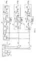
- FIG. 2 shows a preferred embodiment of the invention.
- the first compensation device comprises a thyristor-controlled reactor 3ab, 3bc, 3ca for each one of the three phases of the ac network.
- the thyristor-controlled reactors are connected in a ⁇ -connection.
- a piece of control equipment 7ab is associated with the thyristor-controlled reactor 3ab in order to form a control order ⁇ refab therefor in a manner which will be described in more detail below.
- the control equipment 7ab comprises a calculating member 8ab which, in dependence on values supplied thereto, forms a reference value Bref 1 ab for the susceptance reference, and a control member 9ab which, in dependence thereon, forms the control order ⁇ refab .
- the calculating member 8ab comprises a mean-value forming member 81, a filter member 82 with a low-pass characteristic, a difference-forming member 83ab, and a multiplying member 84ab.
- the filter member 82 may, for example, as illustrated in the figure, be designed with a simple time constant, typically of the order of magnitude of 1 second.
- the first reference value Bref 1 ab for the susceptance is formed as follows.
- the above-mentioned amplitude values U ab , U bc , U ca of the voltage of the load are sensed continuously in some manner known per se by means of the voltage-measuring devices 5ab, 5bc, 5c, respectively.
- the amplitude values U ab , U bc , U ca are supplied to the mean-value forming member 81, which, in dependence thereon, forms a calculated voltage mean value U AV as the mean value of the amplitude mean values supplied thereto.
- the output signal U AV from the member 81 is supplied to the filter member 82, which as output signal forms a filtered voltage mean value U AV ' .
- the difference-forming member 83ab is supplied with the filtered voltage mean value U AV ' and the amplitude value U ab , and forms as output signal a difference ⁇ U ab of the voltage values supplied thereto, which difference constitutes an amplitude deviation between the voltage mean value and the amplitude value.
- the amplitude deviation and an amplification factor K are supplied to the multiplying member 84ab, which, as output signal, forms the first reference value Bref 1 ab as the product of the values of the amplitude deviation and of the amplification factor supplied thereto.
- the first reference value Bref 1 ab is supplied, together with the second reference value Bref 2 ab and the third reference value Bref 3 ab, to a summing member 91ab comprised in the control member 9ab, which summing member 91ab, as output signal, forms a susceptance reference Brefab for the thyristor-controlled reactor 3ab as the sum of the reference values supplied thereto.
- a function-forming member 92ab comprised in the control member 9ab is supplied with the susceptance reference and forms, in dependence thereon, the control order ⁇ refab for the thyristor-controlled reactor 3ab based on the expression (1) above.
- the pieces of control equipment 7bc and 7ca are associated with the thyristor-controlled reactors 3bc and 3ca, respectively.
- These pieces of control equipment are of the same kind as the control equipment 7ab and thus comprise calculating members 8bc and 8ca, respectively, as well as control members 9bc and 9ca, respectively, which form control orders ⁇ refbc and ⁇ refca for the respective thyristor-controlled reactor.
- the pieces of control equipment 7bc and 7ca do not comprise any mean-value forming member or any filter member corresponding to the mean-value forming member 81 and the filter member 82 described above.
- the filtered voltage mean value U AV ' from the filter member 82 is supplied to the difference-forming members 83bcc and 83ca, respectively.
- the device shown in Figure 1B differs from the device described above, and shown in Figure 1A, only as regards the measurement of current.
- the device described with reference to Figure 1A measures the current that is consumed by the industrial load.
- the device shown in Figure 1B measures the current that is consumed jointly by the industrial load and the second compensation device.
- the second reference value Bref 2 xy for the susceptance of the first compensation device is formed in a manner known per se in dependence on the reactive power consumption of the industrial load, that is, in this embodiment the arc furnace.
- the values of currents and voltages are sensed with the voltage-measuring device 5 and the current-measuring device 6 and are supplied to the calculating member 10.
- the calculating member 10 forms, in dependence on sensed voltages and currents, in some manner known per se, the calculated values of active and reactive power based on the following known equations for transformation from a three-phase system, the phases of which are designated a, b, c, to an orthogonal two-phase system, the phases of which are designated d and q.
- the controller 15 forms, also in a manner known per se, in dependence on the difference of a power factor sensed for the plant and a reference value therefor, a third reference value Bref 3.
- This reference value Bref 3 is equal for each phase.
- the second and third reference values are supplied, together with the first reference value Bref 1 xy , to the summing member 91, the output signal Brefxy of which constitutes a susceptance reference for the susceptance of the first compensation device.
- the power factor Pf for the transformer, the load and the compensation device is sensed in some manner known per se by means of a measuring member 151 on the primary side of the transformer 12 and is supplied to the controller 15.
- the controller forms the second control signal Bref 3 in dependence on a comparison between the sensed value of the power factor and for a prescribed reference value Pfref .
- the aim of the controller 15 is to maintain an average power factor, for the connected equipment, in accordance with an agreement with the power supplier. This mean value is usually specified over periods of 10-30 minutes, and this controller is thus active in a considerably lower frequency range than those parts of the control equipment 7 which consist of the first calculating member 10 and the preferred embodiment of the invention according to the above.
- the calculating member 81 may be supplied with sensed values of the peak values or the mean values of the voltages, in which case the voltage mean value is formed as a mean value of these amplitude values.
- the invention may, of course, be applied also to the case where the first compensation device comprises thyristor-controlled reactors in Y-connection.
- the calculating member 10 may also be designed as illustrated in Figure 3, comprising a calculating member 101, a filter member 102 with band-pass characteristic, two summators 103, 104 and a quotient-forming member 105.
- the calculating member 101 calculates, in a manner known per se, both the instantaneously consumed active power of the arc furnace and the instantaneously consumed reactive power of the arc furnace, for example via transformation of sensed voltages and currents into an orthogonal two-phase system as described in EP 0 847 612.
- the calculated value of the instantaneously consumed active power is supplied to a filter member 102, the transfer function G(s) of which makes the function member effective in the frequency interval effective for reduction of flicker.
- the output signal of the function member and the calculated value for the consumed reactive power are supplied to a summator 103 which, in a manner known per se, in dependence on these values, forms a sum SQL.
- the summator 104 is supplied with the sum SQL and, with inversed sign, a signal SQF which represents the reactive power generated by the second compensation device.
- the output signal SQr from the summator 104 thus consists of a difference of the supplied signals and constitutes a calculated value of the reactive power which is to be consumed by the first compensation device.
- the quotient-forming member 105 is supplied with the output signal SQr and forms, in a manner known per se, the second reference value Bref 2 xy .
Landscapes
- Engineering & Computer Science (AREA)
- Power Engineering (AREA)
- Control Of Electrical Variables (AREA)
- Supply And Distribution Of Alternating Current (AREA)
Abstract
Description
- Figure 1A
- schematically shows, as a single-line diagram, an ac network with an industrial load and, in the form of a block diagram, a piece of control equipment according to one embodiment of the invention for compensation of the reactive power consumption of the load,
- Figure 1B
- schematically shows, as a single-line diagram, an ac network with an industrial load and, in the form of a block diagram, a piece of control equipment according to an additional embodiment of the invention for compensation of the reactive power consumption of the load,
- Figure 2
- shows an embodiment of a piece of control equipment according to Figures 1A and 1B, and
- Figure 3
- shows a known embodiment of a calculating member in a piece of control equipment according to Figures 1A and 1B.
Claims (8)
- A method for compensation of the reactive power consumption of an industrial load (2), preferably an electric arc furnace or a plant for rolling of metallic materials, supplied from a three-phase (a, b, c) electric ac network (1), wherein a first compensation device (3, 3ab, 3bc, 3ca) for controllable consumption of reactive power and a second compensation device (4) for generation of reactive power are both connected to the electric power network in a parallel connection with the load, the first compensation device comprising a thyristor-controlled reactor (31, 32) for each of the phases of the ac network, whereby the instantaneous consumption of reactive power (Q(t)) by the load is determined, and a control order ( αrefxy , αrefab , αrefbc , αrefca ) for phase-angle control of the thyristor-controlled reactors is formed in dependence thereon, characterized in that,
for each of the thyristor-controlled reactors, an amplitude value (Uab , Ubc , Uca ) for a voltage is sensed, which voltage represents the voltage across said reactor,
a voltage mean value (UAV, UAV') is formed as the mean value of said amplitude values,
for each of the thyristor-controlled reactors, an amplitude deviation (ΔUab, ΔUbc, ΔUca) is formed as a difference of the voltage mean value and the amplitude value associated with the thyristor-controlled reactor, and that
for each of the thyristor-controlled reactors, a separate control order is formed in dependence on the amplitude deviation for the respective thyristor-controlled reactor. - A method according to claim 1, characterized in that the thyristor-controlled reactors are mutually connected in a Δ-connection.
- A method according to any of claims 1-2, characterized in that the respective control order is formed in dependence also on the instantaneous consumption of active power (P(t)) by the load.
- A method according to any of the preceding claims, characterized in that the total consumption of reactive power by the load and the second compensation device is determined and that the respective control order is formed in dependence thereon.
- A device for compensation of the reactive power consumption of an industrial load (2), preferably an electric arc furnace or a plant for rolling of metallic materials, supplied from a three-phase (a, b, c) electric ac network (1), comprising a first compensation device (3, 3ab, 3bc, 3ca) for controllable consumption of reactive power and a second compensation device (4) for generation of reactive power, both of said compensation devices being connected to the electric power network in a parallel connection with the load, the first compensation device comprising a thyristor-controlled reactor (31, 32) for each of the phases of the ac network, for each of the thyristor-controlled reactors voltage-measuring devices (5, 5ab, 5bc, 5ca) for sensing of amplitude values (Uab, Ubc, Uca ) for a voltage which represents the voltage across the same, current-measuring devices (6) for sensing of the respective current (Ia , Ib, Ic ) at the load, and control equipment (7, 7ab, 7bc, 7ca) which is supplied with measured values of the sensed amplitude values for voltages and currents, the control equipment comprising means (101) for determining the instantaneous consumption of reactive power (Q(t)) by the load, and a control device (9) which, in dependence thereon, forms a control order ( αrefxy , αrefab , αrefbc , αrefca ) for the thyristor-controlled reactors and supplies the control order thereto, characterized in that the control equipment comprises
means (81, 82) for forming a voltage mean value (UAV, UAV') as the mean value of said amplitude values for voltage,
means (83ab, 83bc, 83ca) for forming, for each of the thyristor-controlled reactors, an amplitude deviation (ΔUab, ΔUbc, ΔUca) as a difference of the voltage mean value and the amplitude value associated with the thyristor-controlled reactor, and
means (84ab, 84bc, 84ca, 91, 91ab, 91bc, 91ca, 92, 92ab, 92bc, 92ca) for forming, for each of the thyristor-controlled reactors, a separate control order in dependence on the amplitude deviation for the respective thyristor-controlled reactor. - A device according to claim 5, characterized in that the thyristor-controlled reactors are mutually connected in a Δ-connection.
- A device according to any of claims 5-6, characterized in that the control equipment comprises means (101) for determining the instantaneous consumption of active power (P(t)) by the load, and means (102-105, 91, 91ab, 91bc, 91ca) for forming the respective control order in dependence thereon.
- A device according to any of claims 5-7, characterized in that it comprises current-measuring devices for sensing currents flowing to the parallel connection that is constituted by the load and the second compensation device, and that the control equipment comprises means (101) for determining the total consumption of reactive power by the load and the second compensation device, the control device forming the respective control order in dependence thereon.
Applications Claiming Priority (2)
| Application Number | Priority Date | Filing Date | Title |
|---|---|---|---|
| SE0103985 | 2001-11-28 | ||
| SE0103985A SE523039C2 (en) | 2001-11-28 | 2001-11-28 | Method and apparatus for compensating the consumption of reactive power by an industrial load |
Publications (3)
| Publication Number | Publication Date |
|---|---|
| EP1318588A2 true EP1318588A2 (en) | 2003-06-11 |
| EP1318588A3 EP1318588A3 (en) | 2008-08-13 |
| EP1318588B1 EP1318588B1 (en) | 2011-12-28 |
Family
ID=20286129
Family Applications (1)
| Application Number | Title | Priority Date | Filing Date |
|---|---|---|---|
| EP02079958A Expired - Lifetime EP1318588B1 (en) | 2001-11-28 | 2002-11-27 | A method and a device for compensation of the comsumption of reactive power by an industrial load |
Country Status (6)
| Country | Link |
|---|---|
| US (1) | US6674267B2 (en) |
| EP (1) | EP1318588B1 (en) |
| CN (1) | CN1320719C (en) |
| AT (1) | ATE539476T1 (en) |
| ES (1) | ES2376192T3 (en) |
| SE (1) | SE523039C2 (en) |
Cited By (5)
| Publication number | Priority date | Publication date | Assignee | Title |
|---|---|---|---|---|
| RU2280934C1 (en) * | 2005-03-30 | 2006-07-27 | Открытое Акционерное Общество "Федеральная Сетевая Компания Единой Энергетической Системы" (Оао "Фск Еэс") | Method for reactive power correction device |
| CN102280881A (en) * | 2011-08-05 | 2011-12-14 | 中国电力科学研究院 | Three-phase static var compensator (SVC) device for electrified railway traction side |
| CN106134026A (en) * | 2014-03-31 | 2016-11-16 | 西门子公司 | For dynamically adjusting the apparatus and method of electric arc furnace |
| CN108899915A (en) * | 2018-07-05 | 2018-11-27 | 郑州耀冉节能科技有限公司 | A kind of operation/cutting method of reactive power compensation device and its capacitor group |
| RU2686114C1 (en) * | 2018-06-27 | 2019-04-24 | Акционерное общество "Научно-технический центр Федеральной сетевой компании Единой энергетической системы" | Method for compensation of voltage unbalance in three-phase network |
Families Citing this family (15)
| Publication number | Priority date | Publication date | Assignee | Title |
|---|---|---|---|---|
| US7642666B2 (en) * | 2006-11-02 | 2010-01-05 | Hitachi, Ltd. | Wind power generation apparatus, wind power generation system and power system control apparatus |
| US7940029B2 (en) * | 2008-07-02 | 2011-05-10 | American Superconductor Corporation | Static VAR corrector |
| US20100162024A1 (en) * | 2008-12-24 | 2010-06-24 | Benjamin Kuris | Enabling a Charge Limited Device to Operate for a Desired Period of Time |
| MX2011010629A (en) * | 2009-04-09 | 2011-11-02 | Abb Technology Ag | An arrangement for exchanging power. |
| US8164314B2 (en) * | 2009-05-07 | 2012-04-24 | Toyota Motor Engineering & Manufacturing North America, Inc. | Distributed capacitor bank controllers and methods thereof |
| CN103119821B (en) | 2010-09-30 | 2016-01-13 | Abb研究有限公司 | Multiterminal HVDC system coordination controls |
| RU2518149C2 (en) * | 2012-09-18 | 2014-06-10 | Открытое Акционерное Общество "Федеральная Сетевая Компания Единой Энергетической Системы" (Оао "Фск Еэс") | Controlled reactor with three-leg core |
| CN104348160A (en) * | 2013-07-29 | 2015-02-11 | 青岛菲特电器科技有限公司 | Line series voltage control device for electric reactor |
| ES2632780T3 (en) * | 2013-08-19 | 2017-09-15 | Siemens Aktiengesellschaft | Regulation procedure for automatic switching converters, to regulate the power exchange |
| KR20170139399A (en) * | 2016-06-09 | 2017-12-19 | 엘에스산전 주식회사 | Reactive power compensation system and method thereof |
| RU2640196C1 (en) * | 2016-09-12 | 2017-12-27 | Акционерное общество "Проектно-изыскательский и научно-исследовательский институт по проектированию энергетических систем и электрических сетей "ЭНЕРГОСЕТЬПРОЕКТ" (АО "Институт "ЭНЕРГОСЕТЬПРОЕКТ") | High-voltage electric transmission line with earth-wire |
| IT201800004847A1 (en) * | 2018-04-24 | 2019-10-24 | METHOD OF MELTING IN AN ELECTRIC ARC OVEN AND RELATED EQUIPMENT | |
| JP7013096B2 (en) * | 2018-09-19 | 2022-01-31 | 東芝三菱電機産業システム株式会社 | Static varsator |
| RU197555U1 (en) * | 2019-08-01 | 2020-05-13 | Валерий Павлович Бобров | DEVICE FOR CONTROL AND MANAGEMENT OF POWER OF ELECTRIC NETWORK |
| CN111864735B (en) * | 2020-07-22 | 2024-04-16 | 安徽交通职业技术学院 | A switching compensation system |
Family Cites Families (8)
| Publication number | Priority date | Publication date | Assignee | Title |
|---|---|---|---|---|
| US4451777A (en) * | 1981-09-10 | 1984-05-29 | Westinghouse Electric Corp. | Static VAR generation for transmission line compensation |
| JPS6366617A (en) | 1986-09-09 | 1988-03-25 | Toshiba Corp | Reactive power compensator |
| US5227713A (en) * | 1991-08-08 | 1993-07-13 | Electric Power Research Institute | Vernier control system for subsynchronous resonance mitigation |
| JP3130694B2 (en) * | 1993-02-04 | 2001-01-31 | 株式会社東芝 | Voltage fluctuation and harmonic suppression device |
| JPH0715875A (en) * | 1993-06-24 | 1995-01-17 | Toshiba Corp | Controller for reactive power compensator |
| SE501786C2 (en) * | 1993-09-20 | 1995-05-15 | Asea Brown Boveri | A method for monitoring and controlling a plant part connected to an electrical power grid |
| JPH07236230A (en) * | 1994-02-23 | 1995-09-05 | Nissin Electric Co Ltd | Controller for voltage fluctuation suppresser |
| SE515107C2 (en) | 1996-06-17 | 2001-06-11 | Abb Ab | Reactive power compensation method and apparatus |
-
2001
- 2001-11-28 SE SE0103985A patent/SE523039C2/en unknown
-
2002
- 2002-01-02 US US10/032,557 patent/US6674267B2/en not_active Expired - Lifetime
- 2002-11-27 AT AT02079958T patent/ATE539476T1/en active
- 2002-11-27 EP EP02079958A patent/EP1318588B1/en not_active Expired - Lifetime
- 2002-11-27 ES ES02079958T patent/ES2376192T3/en not_active Expired - Lifetime
- 2002-11-28 CN CNB021527938A patent/CN1320719C/en not_active Expired - Fee Related
Cited By (9)
| Publication number | Priority date | Publication date | Assignee | Title |
|---|---|---|---|---|
| RU2280934C1 (en) * | 2005-03-30 | 2006-07-27 | Открытое Акционерное Общество "Федеральная Сетевая Компания Единой Энергетической Системы" (Оао "Фск Еэс") | Method for reactive power correction device |
| CN102280881A (en) * | 2011-08-05 | 2011-12-14 | 中国电力科学研究院 | Three-phase static var compensator (SVC) device for electrified railway traction side |
| CN102280881B (en) * | 2011-08-05 | 2015-03-25 | 中国电力科学研究院 | Three-phase static var compensator (SVC) device for electrified railway traction side |
| CN106134026A (en) * | 2014-03-31 | 2016-11-16 | 西门子公司 | For dynamically adjusting the apparatus and method of electric arc furnace |
| CN106134026B (en) * | 2014-03-31 | 2018-11-09 | 西门子公司 | Device and method for dynamically adjusting electric arc furnaces |
| US10716176B2 (en) | 2014-03-31 | 2020-07-14 | Siemens Aktiengesellschaft | Apparatus and method for dynamically adjusting an electric arc furnace |
| RU2686114C1 (en) * | 2018-06-27 | 2019-04-24 | Акционерное общество "Научно-технический центр Федеральной сетевой компании Единой энергетической системы" | Method for compensation of voltage unbalance in three-phase network |
| CN108899915A (en) * | 2018-07-05 | 2018-11-27 | 郑州耀冉节能科技有限公司 | A kind of operation/cutting method of reactive power compensation device and its capacitor group |
| CN108899915B (en) * | 2018-07-05 | 2021-09-24 | 郑州耀冉节能科技有限公司 | Reactive power compensation device and switching method of capacitor bank thereof |
Also Published As
| Publication number | Publication date |
|---|---|
| SE523039C2 (en) | 2004-03-23 |
| EP1318588B1 (en) | 2011-12-28 |
| SE0103985L (en) | 2003-05-29 |
| ES2376192T3 (en) | 2012-03-09 |
| ATE539476T1 (en) | 2012-01-15 |
| US20030098672A1 (en) | 2003-05-29 |
| CN1459907A (en) | 2003-12-03 |
| US6674267B2 (en) | 2004-01-06 |
| EP1318588A3 (en) | 2008-08-13 |
| CN1320719C (en) | 2007-06-06 |
Similar Documents
| Publication | Publication Date | Title |
|---|---|---|
| EP1318588B1 (en) | A method and a device for compensation of the comsumption of reactive power by an industrial load | |
| US6114841A (en) | Method and device for compensation of reactive power | |
| Jou | Performance comparison of the three-phase active-power-filter algorithms | |
| US7688043B2 (en) | Reactive-power control apparatus and reactive-power compensator using the same | |
| AU721378B2 (en) | Method and apparatus for power factor correction by means of a compensation device having a pulse converter | |
| Cavaliere et al. | Multi-pulse STATCOM operation under unbalanced voltages | |
| EP0239278B1 (en) | Capacitor apparatus for reactive power compensation | |
| Ranjbaran et al. | A power sharing scheme for voltage unbalance and harmonics compensation in an islanded microgrid | |
| KR101606882B1 (en) | Apparatus for compensating reactive power and method for the same | |
| US20100327823A1 (en) | Reactive power compensation circuit | |
| CN101080861B (en) | Device and method for controlling electrical power flow in a high-voltage network | |
| WO1997022169A2 (en) | Voltage based var compensation system | |
| US6348778B1 (en) | Method and apparatus for improving the voltage quality of secondary power supply unit | |
| WO1991011841A1 (en) | Cycloconvertor equipment | |
| US5672957A (en) | Method and device for reducing voltage imbalances in a three-phase network by means of a static compensator | |
| Lee et al. | Combined compensation structure of a static Var compensator and an active filter for unbalanced three-phase distribution feeders with harmonic distortion | |
| JP2006054944A (en) | Apparatus and method for compensating voltage imbalance in distribution system | |
| Matsui et al. | A detecting method for active-reactive-negative-sequence powers and its application | |
| US7173349B2 (en) | Equipment and method for exchanging power, in shunt connection, with an electric power network, and use of such equipment | |
| EP0551683A1 (en) | Improved feedback control system for static volt ampere reactive compensator with thyristor controlled reactances | |
| US20040052015A1 (en) | Device and a method for voltage control in an electric transmission network | |
| JP3135600B2 (en) | Unbalance compensator | |
| Su et al. | Hybrid filter application for power quality improvement | |
| Mienski et al. | Control algorithm for the 12-pulse SVC | |
| Chen et al. | Design of an online microprocessor based individual phase control of a static VAr compensator |
Legal Events
| Date | Code | Title | Description |
|---|---|---|---|
| PUAI | Public reference made under article 153(3) epc to a published international application that has entered the european phase |
Free format text: ORIGINAL CODE: 0009012 |
|
| 17P | Request for examination filed |
Effective date: 20021220 |
|
| AK | Designated contracting states |
Designated state(s): AT BE BG CH CY CZ DE DK EE ES FI FR GB GR IE IT LI LU MC NL PT SE SK TR |
|
| AX | Request for extension of the european patent |
Extension state: AL LT LV MK RO SI |
|
| PUAL | Search report despatched |
Free format text: ORIGINAL CODE: 0009013 |
|
| AK | Designated contracting states |
Kind code of ref document: A3 Designated state(s): AT BE BG CH CY CZ DE DK EE ES FI FR GB GR IE IT LI LU MC NL PT SE SK TR |
|
| AX | Request for extension of the european patent |
Extension state: AL LT LV MK RO SI |
|
| AKX | Designation fees paid |
Designated state(s): AT BE BG CH CY CZ DE DK EE ES FI FR GB GR IE IT LI LU MC NL PT SE SK TR |
|
| GRAP | Despatch of communication of intention to grant a patent |
Free format text: ORIGINAL CODE: EPIDOSNIGR1 |
|
| GRAS | Grant fee paid |
Free format text: ORIGINAL CODE: EPIDOSNIGR3 |
|
| GRAA | (expected) grant |
Free format text: ORIGINAL CODE: 0009210 |
|
| AK | Designated contracting states |
Kind code of ref document: B1 Designated state(s): AT BE BG CH CY CZ DE DK EE ES FI FR GB GR IE IT LI LU MC NL PT SE SK TR |
|
| REG | Reference to a national code |
Ref country code: GB Ref legal event code: FG4D |
|
| REG | Reference to a national code |
Ref country code: CH Ref legal event code: EP |
|
| REG | Reference to a national code |
Ref country code: DE Ref legal event code: R081 Ref document number: 60241834 Country of ref document: DE Owner name: ABB SCHWEIZ AG, CH Free format text: FORMER OWNER: ABB AB, VAESTERAS, SE |
|
| REG | Reference to a national code |
Ref country code: AT Ref legal event code: REF Ref document number: 539476 Country of ref document: AT Kind code of ref document: T Effective date: 20120115 |
|
| REG | Reference to a national code |
Ref country code: IE Ref legal event code: FG4D |
|
| REG | Reference to a national code |
Ref country code: SE Ref legal event code: TRGR |
|
| REG | Reference to a national code |
Ref country code: DE Ref legal event code: R096 Ref document number: 60241834 Country of ref document: DE Effective date: 20120301 |
|
| REG | Reference to a national code |
Ref country code: ES Ref legal event code: FG2A Ref document number: 2376192 Country of ref document: ES Kind code of ref document: T3 Effective date: 20120309 |
|
| REG | Reference to a national code |
Ref country code: NL Ref legal event code: VDEP Effective date: 20111228 |
|
| PG25 | Lapsed in a contracting state [announced via postgrant information from national office to epo] |
Ref country code: GR Free format text: LAPSE BECAUSE OF FAILURE TO SUBMIT A TRANSLATION OF THE DESCRIPTION OR TO PAY THE FEE WITHIN THE PRESCRIBED TIME-LIMIT Effective date: 20120329 |
|
| PG25 | Lapsed in a contracting state [announced via postgrant information from national office to epo] |
Ref country code: CY Free format text: LAPSE BECAUSE OF FAILURE TO SUBMIT A TRANSLATION OF THE DESCRIPTION OR TO PAY THE FEE WITHIN THE PRESCRIBED TIME-LIMIT Effective date: 20111228 Ref country code: BE Free format text: LAPSE BECAUSE OF FAILURE TO SUBMIT A TRANSLATION OF THE DESCRIPTION OR TO PAY THE FEE WITHIN THE PRESCRIBED TIME-LIMIT Effective date: 20111228 |
|
| PG25 | Lapsed in a contracting state [announced via postgrant information from national office to epo] |
Ref country code: NL Free format text: LAPSE BECAUSE OF FAILURE TO SUBMIT A TRANSLATION OF THE DESCRIPTION OR TO PAY THE FEE WITHIN THE PRESCRIBED TIME-LIMIT Effective date: 20111228 Ref country code: EE Free format text: LAPSE BECAUSE OF FAILURE TO SUBMIT A TRANSLATION OF THE DESCRIPTION OR TO PAY THE FEE WITHIN THE PRESCRIBED TIME-LIMIT Effective date: 20111228 Ref country code: CZ Free format text: LAPSE BECAUSE OF FAILURE TO SUBMIT A TRANSLATION OF THE DESCRIPTION OR TO PAY THE FEE WITHIN THE PRESCRIBED TIME-LIMIT Effective date: 20111228 Ref country code: SK Free format text: LAPSE BECAUSE OF FAILURE TO SUBMIT A TRANSLATION OF THE DESCRIPTION OR TO PAY THE FEE WITHIN THE PRESCRIBED TIME-LIMIT Effective date: 20111228 Ref country code: BG Free format text: LAPSE BECAUSE OF FAILURE TO SUBMIT A TRANSLATION OF THE DESCRIPTION OR TO PAY THE FEE WITHIN THE PRESCRIBED TIME-LIMIT Effective date: 20120328 |
|
| PG25 | Lapsed in a contracting state [announced via postgrant information from national office to epo] |
Ref country code: PT Free format text: LAPSE BECAUSE OF FAILURE TO SUBMIT A TRANSLATION OF THE DESCRIPTION OR TO PAY THE FEE WITHIN THE PRESCRIBED TIME-LIMIT Effective date: 20120430 |
|
| REG | Reference to a national code |
Ref country code: AT Ref legal event code: MK05 Ref document number: 539476 Country of ref document: AT Kind code of ref document: T Effective date: 20111228 |
|
| PG25 | Lapsed in a contracting state [announced via postgrant information from national office to epo] |
Ref country code: DK Free format text: LAPSE BECAUSE OF FAILURE TO SUBMIT A TRANSLATION OF THE DESCRIPTION OR TO PAY THE FEE WITHIN THE PRESCRIBED TIME-LIMIT Effective date: 20111228 |
|
| PLBE | No opposition filed within time limit |
Free format text: ORIGINAL CODE: 0009261 |
|
| STAA | Information on the status of an ep patent application or granted ep patent |
Free format text: STATUS: NO OPPOSITION FILED WITHIN TIME LIMIT |
|
| 26N | No opposition filed |
Effective date: 20121001 |
|
| REG | Reference to a national code |
Ref country code: DE Ref legal event code: R097 Ref document number: 60241834 Country of ref document: DE Effective date: 20121001 |
|
| PG25 | Lapsed in a contracting state [announced via postgrant information from national office to epo] |
Ref country code: AT Free format text: LAPSE BECAUSE OF FAILURE TO SUBMIT A TRANSLATION OF THE DESCRIPTION OR TO PAY THE FEE WITHIN THE PRESCRIBED TIME-LIMIT Effective date: 20111228 |
|
| PG25 | Lapsed in a contracting state [announced via postgrant information from national office to epo] |
Ref country code: FI Free format text: LAPSE BECAUSE OF FAILURE TO SUBMIT A TRANSLATION OF THE DESCRIPTION OR TO PAY THE FEE WITHIN THE PRESCRIBED TIME-LIMIT Effective date: 20111228 |
|
| REG | Reference to a national code |
Ref country code: CH Ref legal event code: PL |
|
| PG25 | Lapsed in a contracting state [announced via postgrant information from national office to epo] |
Ref country code: CH Free format text: LAPSE BECAUSE OF NON-PAYMENT OF DUE FEES Effective date: 20121130 Ref country code: LI Free format text: LAPSE BECAUSE OF NON-PAYMENT OF DUE FEES Effective date: 20121130 |
|
| REG | Reference to a national code |
Ref country code: IE Ref legal event code: MM4A |
|
| PG25 | Lapsed in a contracting state [announced via postgrant information from national office to epo] |
Ref country code: IE Free format text: LAPSE BECAUSE OF NON-PAYMENT OF DUE FEES Effective date: 20121127 |
|
| PG25 | Lapsed in a contracting state [announced via postgrant information from national office to epo] |
Ref country code: MC Free format text: LAPSE BECAUSE OF NON-PAYMENT OF DUE FEES Effective date: 20121130 Ref country code: TR Free format text: LAPSE BECAUSE OF FAILURE TO SUBMIT A TRANSLATION OF THE DESCRIPTION OR TO PAY THE FEE WITHIN THE PRESCRIBED TIME-LIMIT Effective date: 20111228 |
|
| PG25 | Lapsed in a contracting state [announced via postgrant information from national office to epo] |
Ref country code: LU Free format text: LAPSE BECAUSE OF NON-PAYMENT OF DUE FEES Effective date: 20121127 |
|
| REG | Reference to a national code |
Ref country code: FR Ref legal event code: PLFP Year of fee payment: 14 |
|
| REG | Reference to a national code |
Ref country code: FR Ref legal event code: PLFP Year of fee payment: 15 |
|
| PGFP | Annual fee paid to national office [announced via postgrant information from national office to epo] |
Ref country code: ES Payment date: 20161114 Year of fee payment: 15 Ref country code: IT Payment date: 20161123 Year of fee payment: 15 |
|
| REG | Reference to a national code |
Ref country code: FR Ref legal event code: PLFP Year of fee payment: 16 |
|
| REG | Reference to a national code |
Ref country code: GB Ref legal event code: 732E Free format text: REGISTERED BETWEEN 20180327 AND 20180328 |
|
| REG | Reference to a national code |
Ref country code: DE Ref legal event code: R081 Ref document number: 60241834 Country of ref document: DE Owner name: ABB SCHWEIZ AG, CH Free format text: FORMER OWNER: ABB AB, VAESTERAS, SE |
|
| PG25 | Lapsed in a contracting state [announced via postgrant information from national office to epo] |
Ref country code: IT Free format text: LAPSE BECAUSE OF NON-PAYMENT OF DUE FEES Effective date: 20171127 |
|
| REG | Reference to a national code |
Ref country code: FR Ref legal event code: TP Owner name: ABB SCHWEIZ AG, CH Effective date: 20181106 |
|
| PG25 | Lapsed in a contracting state [announced via postgrant information from national office to epo] |
Ref country code: ES Free format text: LAPSE BECAUSE OF NON-PAYMENT OF DUE FEES Effective date: 20171128 |
|
| PGFP | Annual fee paid to national office [announced via postgrant information from national office to epo] |
Ref country code: SE Payment date: 20201125 Year of fee payment: 19 Ref country code: FR Payment date: 20201120 Year of fee payment: 19 Ref country code: GB Payment date: 20201120 Year of fee payment: 19 Ref country code: DE Payment date: 20201119 Year of fee payment: 19 |
|
| REG | Reference to a national code |
Ref country code: DE Ref legal event code: R119 Ref document number: 60241834 Country of ref document: DE |
|
| GBPC | Gb: european patent ceased through non-payment of renewal fee |
Effective date: 20211127 |
|
| PG25 | Lapsed in a contracting state [announced via postgrant information from national office to epo] |
Ref country code: SE Free format text: LAPSE BECAUSE OF NON-PAYMENT OF DUE FEES Effective date: 20211128 |
|
| PG25 | Lapsed in a contracting state [announced via postgrant information from national office to epo] |
Ref country code: GB Free format text: LAPSE BECAUSE OF NON-PAYMENT OF DUE FEES Effective date: 20211127 Ref country code: DE Free format text: LAPSE BECAUSE OF NON-PAYMENT OF DUE FEES Effective date: 20220601 |
|
| PG25 | Lapsed in a contracting state [announced via postgrant information from national office to epo] |
Ref country code: FR Free format text: LAPSE BECAUSE OF NON-PAYMENT OF DUE FEES Effective date: 20211130 |