EP1318570A1 - A connector and method of assembling it - Google Patents
A connector and method of assembling it Download PDFInfo
- Publication number
- EP1318570A1 EP1318570A1 EP02027507A EP02027507A EP1318570A1 EP 1318570 A1 EP1318570 A1 EP 1318570A1 EP 02027507 A EP02027507 A EP 02027507A EP 02027507 A EP02027507 A EP 02027507A EP 1318570 A1 EP1318570 A1 EP 1318570A1
- Authority
- EP
- European Patent Office
- Prior art keywords
- connector
- connector housing
- grommet
- housings
- housing
- Prior art date
- Legal status (The legal status is an assumption and is not a legal conclusion. Google has not performed a legal analysis and makes no representation as to the accuracy of the status listed.)
- Granted
Links
- 238000000034 method Methods 0.000 title claims description 7
- 238000007789 sealing Methods 0.000 claims abstract description 109
- 238000010276 construction Methods 0.000 description 5
- 230000000694 effects Effects 0.000 description 4
- 210000000078 claw Anatomy 0.000 description 2
- 230000013011 mating Effects 0.000 description 2
- 230000006835 compression Effects 0.000 description 1
- 238000007906 compression Methods 0.000 description 1
- 230000008878 coupling Effects 0.000 description 1
- 238000010168 coupling process Methods 0.000 description 1
- 238000005859 coupling reaction Methods 0.000 description 1
- 230000001419 dependent effect Effects 0.000 description 1
- 238000000465 moulding Methods 0.000 description 1
- 239000012858 resilient material Substances 0.000 description 1
- 239000011347 resin Substances 0.000 description 1
- 229920005989 resin Polymers 0.000 description 1
Images


Classifications
-
- H—ELECTRICITY
- H01—ELECTRIC ELEMENTS
- H01R—ELECTRICALLY-CONDUCTIVE CONNECTIONS; STRUCTURAL ASSOCIATIONS OF A PLURALITY OF MUTUALLY-INSULATED ELECTRICAL CONNECTING ELEMENTS; COUPLING DEVICES; CURRENT COLLECTORS
- H01R13/00—Details of coupling devices of the kinds covered by groups H01R12/70 or H01R24/00 - H01R33/00
- H01R13/73—Means for mounting coupling parts to apparatus or structures, e.g. to a wall
- H01R13/74—Means for mounting coupling parts in openings of a panel
-
- H—ELECTRICITY
- H01—ELECTRIC ELEMENTS
- H01R—ELECTRICALLY-CONDUCTIVE CONNECTIONS; STRUCTURAL ASSOCIATIONS OF A PLURALITY OF MUTUALLY-INSULATED ELECTRICAL CONNECTING ELEMENTS; COUPLING DEVICES; CURRENT COLLECTORS
- H01R13/00—Details of coupling devices of the kinds covered by groups H01R12/70 or H01R24/00 - H01R33/00
- H01R13/46—Bases; Cases
- H01R13/52—Dustproof, splashproof, drip-proof, waterproof, or flameproof cases
- H01R13/5202—Sealing means between parts of housing or between housing part and a wall, e.g. sealing rings
-
- H—ELECTRICITY
- H01—ELECTRIC ELEMENTS
- H01R—ELECTRICALLY-CONDUCTIVE CONNECTIONS; STRUCTURAL ASSOCIATIONS OF A PLURALITY OF MUTUALLY-INSULATED ELECTRICAL CONNECTING ELEMENTS; COUPLING DEVICES; CURRENT COLLECTORS
- H01R13/00—Details of coupling devices of the kinds covered by groups H01R12/70 or H01R24/00 - H01R33/00
- H01R13/46—Bases; Cases
- H01R13/52—Dustproof, splashproof, drip-proof, waterproof, or flameproof cases
- H01R13/5219—Sealing means between coupling parts, e.g. interfacial seal
-
- H—ELECTRICITY
- H01—ELECTRIC ELEMENTS
- H01R—ELECTRICALLY-CONDUCTIVE CONNECTIONS; STRUCTURAL ASSOCIATIONS OF A PLURALITY OF MUTUALLY-INSULATED ELECTRICAL CONNECTING ELEMENTS; COUPLING DEVICES; CURRENT COLLECTORS
- H01R13/00—Details of coupling devices of the kinds covered by groups H01R12/70 or H01R24/00 - H01R33/00
- H01R13/62—Means for facilitating engagement or disengagement of coupling parts or for holding them in engagement
- H01R13/629—Additional means for facilitating engagement or disengagement of coupling parts, e.g. aligning or guiding means, levers, gas pressure electrical locking indicators, manufacturing tolerances
- H01R13/62933—Comprising exclusively pivoting lever
- H01R13/62938—Pivoting lever comprising own camming means
Definitions
- sealing is provided between the connector housings by compressing the sealing portion in the directions normal to the connecting direction, the connector housings are prevented from relatively shifting in the separating direction upon receiving a resilient force of the sealing portion. Even if the connector housings should be shifted relatively to each other in the separating direction, the sealing portion is only moved in the separating direction while being kept in a compressed state. Therefore, the sealing portion can constantly display its sealing function.
- the sealing portion is at least partly radially (or in a direction substantially normal to the connecting direction) arranged or sandwiched or fitted between the first connector housing and the second connector housing thereby being compressed in directions substantially normal to the connecting direction.
- a movable member is provided on one of the first and second connector housings for displaying a cam action in order to connect or assist the connection of the first and second connector housings with each other.
- the movable member comprises a lever formed with at least one cam groove, the lever being provided on one of the connector housings and the other one of the connector housings is provided with at least one cam follower engageable with the cam groove(s), the cam follower is displaced along the cam groove as the lever is rotated, thereby connecting and separating the second connector housing with and from the first connector housing.
- a connector comprising a waiting-side connector housing mountable onto a panel and a watertight connector housing engageable with the waiting-side connector housing, wherein:
- sealing is provided between the connector housings by compressing the sealing portion in the directions normal to the connecting direction, the watertight connector housing is prevented from shifting in the separating direction upon receiving a resilient force of the sealing portion even if a supporting portion between the lever and the watertight connector housing shake with respect to each other due to weakened rigidity. Even if the watertight connector housing should be shifted in the separating direction, the sealing portion is only moved in the separating direction while being kept in a compressed state. Therefore, the sealing portion can constantly display its sealing function.
- the sealing portion is formed at such a position as to be squeezed between surfaces of the connector housings opposed to each other in the directions substantially normal to the connecting direction of the connector housings.
- the connector housings are at least partly connected with each other by operating a movable member provided on one of the first and second connector housings thereby displaying a cam action in order to connect or assist the connection of the first and second connector housings with each other.
- a connector comprising first and second housings connectable with one another along a connecting direction, wherein:
- a movable member is provided on one of the first and second housings for displaying a cam action to connect the first and second housings with each other.
- the movable member comprises a lever formed with at least one cam groove, the lever being provided on one of the housings and the other of the housings having at least one cam follower engageable with the cam groove, the cam follower being displaced along the cam groove as the lever is rotated, thereby connecting and separating the second housing with and from the first housing.
- a connector comprising first and second housings connectable with one another along a connecting direction, wherein:
- a connector of this embodiment is comprised of a receiving or waiting-side or first connector housing 10 (hereinafter, referred to as a waiting-side housing 10) and a watertight or second connector housing 11 (hereinafter, referred to as watertight housing 11) which are connectable with each other along a connecting direction CD.
- a receiving or waiting-side or first connector housing 10 hereinafter, referred to as a waiting-side housing 10
- a watertight or second connector housing 11 hereinafter, referred to as watertight housing 11
- the leading end of the receptacle 14 is at least partly inserted or mountable into the mount opening Pa formed in the panel P, an engaging claw 17 provided at the upper end of the receptacle 14 is engaged or engageable with the upper edge of the mount opening Pa, and a resilient locking claw 17A provided at the lower end of the receptacle 14 is engaged or engageable with the lower edge of the mount opening Pa while being resiliently deformed.
- the sealing member 16 is substantially closely brought or bringable into contact preferably with the substantially entire circumferential edge of the mount opening Pa, and the panel P and the waiting-side housing 10 are connected with each other while sealing is provided therebetween.
- the receptacle 14 With the waiting-side housing 10 mounted on the panel P, the receptacle 14 is open along the opening edge of or at the mount opening Pa, and the watertight housing 11 at least partly enters the receptacle 14 through an opening portion 14A and is connected with the waiting-side housing 10. Further, a pair of cam followers 19, which preferably are pins concentric with each other, project at the left and right inner surfaces of the receptacle 14.
- the watertight housing 11 is formed with one or more cavities (not shown) for at least partly accommodating one or more, preferably a plurality of female terminals (not shown) therein, and is provided with a grommet 21 made of a rubber or other resilient material which is so mounted from behind as to cover all the outer surfaces of the watertight housing 11 excluding the front surface and a grommet cover 22 made preferably of a hard or shape-maintaining resin to preferably cover the substantially whole body of the grommet 21 excluding the front surface from the back side of the grommet 21.
- a wire draw-out portion 23 preferably in the form of a tube through which a bundle of wires connected with the female terminals are to be inserted or insertable is provided at the back surface of the grommet 21.
- a through hole 24 is formed in the back surface of the grommet cover 22 for avoiding the wire draw-out portion 23, and a pair of shaft pins 25 project at the left and right or lateral outer surfaces of the grommet cover 22.
- a substantially U-shaped lever 18 (as a preferably moving means) is so mounted on the grommet cover 22 as to cross over or bridge or span the grommet cover 22.
- the lever 18 is comprised of a pair of operation arms 26 and an operable portion 27 coupling the operation arms 26 with each other preferably at their leading ends.
- Each operation arm 26 is formed with a bearing hole 28 to be engaged with the corresponding shaft pin 25.
- the lever 18 is rotatable or pivotable about these engaged portions between a (first) position where the lever 18 is substantially located before a connecting operation (see FIG. 2) and a (second) position where the lever is substantially located after (see FIG. 4) the connecting operation.
- the grommet 21 is mounted such that the inner surface thereof is or can be held substantially in close contact with the outer surfaces of the watertight housing 11.
- the front end of the grommet 21 extends to such a position as to be preferably substantially in flush with the leading end of the watertight housing 11.
- a sealing portion 31 is provided at a portion of the leading end of the grommet 21 which is to overlap the squeezing wall 30 of the waiting-side housing 10 along the connecting direction CD when the housings 10, 11 are connected with each other.
- One or more, preferably two lip portions 31A are circumferentially formed on each of the inner and/or outer circumferential surfaces of the sealing portion 31.
- a spacing between peaks of the outer lip portions 31A and the inner circumferential surface of the grommet cover 22 is set to be smaller than the thickness or radial position of the squeezing wall 30, so that the lip portions 31A are compressed in directions substantially normal to a connecting direction between the squeezing wall 30 and the watertight housing 11 when the squeezing wall 30 is fitted into the above clearance between the thinned portion of the grommet cover 22 and the sealing portion 31 thereby deflecting the sealing portion inwardly and compressing it between the squeezing wall 31 and the main body of the watertight connector 11.
- the squeezing wall 30, the sealing portion 31 and the grommet cover 22 are radially arranged (or arranged substantially normal to the connecting direction CD) with respect to each other at such a distance so as to resiliently compress the sealing portion 30 in the direction substantially normal to the connecting direction CD. Therefore, the sealing portion 31 is watertightly or sealingly kept substantially in close contact with the inner circumferential surface of the squeezing wall 30 and the outer circumferential surface of the watertight housing 11, thereby providing sealing between the both housings 10, 11.
- the sealing portion 31 In order to stably provide sealing between the two housings 10, 11, the sealing portion 31 needs to be constantly compressed by exerting a force of the same intensity in the directions of compression of the sealing portion 31 to maintain a close contact state. If the sealing portion 31 is compressed in the directions at an angle comprises between about 70° and about 110° (i.e. substantially normal) to the connecting direction CD by the squeezing wall 30 as in this embodiment, the front end of the sealing portion 31 is substantially not compressed in or along the connecting direction CD since it does not come into contact with the back surface of the receptacle 14.
- the watertight housing 11 is not displaced in separating direction from the waiting-side housing 10 since the sealing portion 31 exerts substantially no resilient force acting in the connecting direction CD on the watertight housing 11. Even if the watertight housing 11 should be moved in the separating direction (or a direction substantially opposite to the connecting direction CD), the sealing portion 31 is only moved backward along the squeezing wall 30 while being compressed. Therefore, there is no change in the compressed state of the sealing portion 31 in the directions substantially normal to the connecting direction CD, i.e. the close contact state of the outer circumferential surface of the watertight housing 11 and the inner circumferential surface of the squeezing wall 30. Thus, sealing can be securely provided between the housings 10, 11.
- the above effects can be obtained by defining the clearance between the sealing portion 31 at the leading end of the grommet 21 and the grommet cover 22, and providing the squeezing wall 30 fittable into the clearance and projecting at the back end of the receptacle 14. Therefore, the constructions of the housings 10, 11 can be simplified.
- An engaging portion 40 is formed at the back surface of a receptacle 14 by forming two annularly projecting squeezing walls 42 at a specified (predetermined or predeterminable) spacing so as to doubly at least partly surround the front side of a main body 12 of a waiting-side housing 10.
- a sealing portion 43 in the form of a wall projects substantially in a connecting direction CD preferably over the substantially entire circumferential surface of the front end of a grommet 21.
- a leading end portion of the sealing portion 43 is formed into a watertight portion 43A preferably having a substantially elliptical cross section or other enlarged cross-section swollen in directions substantially normal to the connecting direction CD.
- a distance between opposed surfaces 40A of the engaging portions 40 is smaller than a radial dimension of the watertight portion 43A along the direction substantially normal to the connecting direction CD.
- a watertight housing 11 is at least partly fitted into the receptacle 14.
- the sealing portion 43 is at least partly fitted into the engaging portion 40, the watertight portion 43A is compressed in the directions substantially normal to the connecting direction CD between the opposite or facing inner surfaces 40A of the engaging portion 40.
- the leading end of the watertight portion 43A preferably is held substantially in close contact with the back surface 40B of the engaging portion 40.
Landscapes
- Connector Housings Or Holding Contact Members (AREA)
Abstract
Description
- The present invention relates to a watertight connector to be mounted on a panel and to a method of assembling it.
- One example of a connector to be mountable on door panels of automotive vehicles is disclosed in Japanese Unexamined Patent Publication No. 11-111385. A waiting-side connector housing 1 of this connector is fitted through a
mount opening 2A formed in apanel 2 as shown in FIG. 7. On the other hand, awaterproof grommet 4 is mounted on awatertight connector housing 3, and a sealingportion 4A is provided at the front end of the opening edge of thegrommet 4. - A
grommet cover 5 is mounted on thewatertight connector housing 3 and alever 6 formed with acam groove 6A is rotatably supported on thegrommet cover 5, whereas a cam follower 1A is formed on the waiting-side connector housing 1. When thelever 6 is rotated, thecam groove 6A and the cam follower 1A are engaged with each other, whereby thewatertight connector housing 3 is pulled into the waiting-side connector housing 1 together with thegrommet cover 5 and thegrommet 4. Further, upon the completion of the rotating operation of thelever 6, the sealingportion 4A of thegrommet 4 is compressed in a connecting directions between aback surface 1B of the waiting-side connector housing 1 and the front end of thegrommet cover 5, thereby providing sealing between the waiting-side andwatertight connector housings 1, 3. - In order to provide secure sealing between the
connector housings 1, 3 having the above construction, the sealingportion 4A of thegrommet 4 needs to be constantly kept in a compressed state in the engaging directions by pushing thewatertight connector housing 3 into the waiting-side connector housing 1 - However, a
shaft 7 and a bearing 6B which form a supporting portion of thelever 6 may inadvertently shake with respect to each other due to an engagement tolerance during molding or weakened rigidity resulting from repeated rotation of thelever 6. Then, a phenomenon will occur where, when theconnector housings 1, 3 are connected with each other, thewatertight connector housing 3 covered by thegrommet 4 and thegrommet cover 5 is shifted by a resilient force of the sealingportion 4A in separating direction from thelever 6 and the waiting-side connector housing 1 immovably locked into each other by the engagement of the cam follower 1A with thecam groove 6A. As a result, the sealingportion 4A cannot be sufficiently pushed against theback surface 1B of the waiting-side connector housing 1, and this may cause insufficient sealing between theconnector housings 1, 3. - The present invention was developed in view of the above problem and an object thereof is to provide secure sealing between a first connector housing, in particular a waiting-side connector housing, and a second connector housing, in particular a watertight connector housing, even if the watertight connector housing has a play in connecting direction.
- This object is solved according to the invention by a connector according to claim 1 and by a method of assembling a connector according to claim 9. Preferred embodiments of the invention are subject of the dependent claims.
- According to the invention, there is provided a connector, comprising a first connector housing mountable onto a panel and a second connector housing engageable or mateable with the first connector housing,
wherein: - the second connector housing is provided with a grommet for substantially covering the second connector housing, and
- the grommet is formed with at least one sealing portion for providing sealing between the connector housings by being compressed in directions substantially normal to a connecting direction when the first connector housing and the second connector housing are connected with each other.
-
- Since sealing is provided between the connector housings by compressing the sealing portion in the directions normal to the connecting direction, the connector housings are prevented from relatively shifting in the separating direction upon receiving a resilient force of the sealing portion. Even if the connector housings should be shifted relatively to each other in the separating direction, the sealing portion is only moved in the separating direction while being kept in a compressed state. Therefore, the sealing portion can constantly display its sealing function.
- According to a preferred embodiment of the invention, the sealing portion is at least partly radially (or in a direction substantially normal to the connecting direction) arranged or sandwiched or fitted between the first connector housing and the second connector housing thereby being compressed in directions substantially normal to the connecting direction.
- Preferably, a movable member is provided on one of the first and second connector housings for displaying a cam action in order to connect or assist the connection of the first and second connector housings with each other.
- Most preferably, the movable member comprises a lever formed with at least one cam groove,
the lever being provided on one of the connector housings and the other one of the connector housings is provided with at least one cam follower engageable with the cam groove(s),
the cam follower is displaced along the cam groove as the lever is rotated, thereby connecting and separating the second connector housing with and from the first connector housing. - According to a further preferred embodiment of the invention, there is provided a connector, comprising a waiting-side connector housing mountable onto a panel and a watertight connector housing engageable with the waiting-side connector housing,
wherein: - the watertight connector housing is provided with a grommet for covering the watertight connector housing and a lever formed with a cam groove,
- the waiting-side connector housing is provided with a cam follower engageable with the cam groove,
- the cam follower is displaced along the cam groove as the lever is rotated, thereby connecting and separating the watertight connector housing with and from the waiting-side connector housing, and
- the grommet is formed with a sealing portion for providing sealing between the connector housings by being compressed in directions normal to a connecting direction when the waiting-side connector housing and the watertight connector housing are connected with each other.
-
- Since sealing is provided between the connector housings by compressing the sealing portion in the directions normal to the connecting direction, the watertight connector housing is prevented from shifting in the separating direction upon receiving a resilient force of the sealing portion even if a supporting portion between the lever and the watertight connector housing shake with respect to each other due to weakened rigidity. Even if the watertight connector housing should be shifted in the separating direction, the sealing portion is only moved in the separating direction while being kept in a compressed state. Therefore, the sealing portion can constantly display its sealing function.
- Preferably, the sealing portion is formed at such a position as to be squeezed between surfaces of the connector housings opposed to each other in the directions substantially normal to the connecting direction of the connector housings.
- The sealing portion is compressed in the directions substantially normal to the connecting direction between the engaging circumferential surfaces of the waiting-side and watertight connector housings to thereby provide sealing between these connector housings. Therefore, the construction can be simplified.
- Most preferably, the sealing portion comprises a portion in the form of a projecting wall and/or a groove which is circumferentially formed on or in a surface of the grommet preferably substantially opposed to a surface of the waiting-side connector housing substantially along the connecting direction of the connector housings, an engaging portion engageable with the sealing portion in the form of a groove and/or a projecting wall is circumferentially formed in or on the surface of the waiting-side connector housing preferably substantially opposed to the surface of the grommet, and the sealing portion can be compressed against the circumferential surface of the engaging portion in the directions substantially normal to the connecting direction of the connector housings.
- As the connector housings are connected, the sealing portion of the grommet is engaged with the engaging portion of the watertight connector housing, and the sealing portion is compressed against the circumferential surface of the mating engaging portion in the directions normal to the connecting direction of the connector housings, thereby providing sealing between the connector housings. Since the opposite side surfaces of the compressed sealing portion are held in close contact with the engaging portion, more secure sealing can be provided between the connector housings.
- Preferably, the sealing portion comes substantially into engagement with the engaging portion both in a direction along the connecting direction and in the directions substantially normal to the connecting direction of the connector housings.
- Most preferably, the second connector housing is provided with a grommet cover for at least partly covering the grommet, wherein in the properly connected state of the connector housings a main body of the second connector housing, a portion of the first connector housing, a portion of the grommet and a portion of the grommet cover are radially arranged (or arranged at an angle different from 0° or 180°, preferably substantially normally to the connecting direction of the connector housings) with respect to each other in this order.
- According to the invention, there is further provided a method of assembling a watertight connector, in particular according to the invention or an embodiment thereof, comprising a first connector housing mountable onto a panel and a second connector housing engageable or mateable with the first connector housing,
wherein: - providing the second connector housing with a grommet for substantially covering the second connector housing, and
- connecting the first and second housings thereby compressing at least one sealing portion of the grommet in directions substantially normal to a connecting direction of the connector housings for providing sealing between the connector housings.
-
- According to a preferred embodiment of the invention, the step of compressing the sealing portion comprises the step of arranging the sealing portion at least partly radially between the first connector housing and the second connector housing thereby compressing the sealing portion in directions substantially normal to the connecting direction.
- Preferably, the connector housings are at least partly connected with each other by operating a movable member provided on one of the first and second connector housings thereby displaying a cam action in order to connect or assist the connection of the first and second connector housings with each other.
- According to the invention, there is further provided a connector comprising first and second housings connectable with one another along a connecting direction, wherein:
- the second housing having a front end and side surfaces extending rearwardly from the front end along the connecting direction;
- a grommet mounted over the second housing and sealingly engaging the side surfaces of the second housing adjacent the front end;
- a grommet cover mounted over the grommet and being spaced outwardly from the grommet adjacent the front end of the second housing;
- the first housing having a receptacle mounted over the grommet cover, a squeezing wall disposed inwardly from the receptacle and inserted between the grommet cover and the grommet at locations adjacent the front end of the second housing, such that the grommet exerts resilient sealing forces against the squeezing wall in directions substantially normal to the connecting direction.
-
- According to a preferred embodiment, a movable member is provided on one of the first and second housings for displaying a cam action to connect the first and second housings with each other.
- Most preferably, the movable member comprises a lever formed with at least one cam groove, the lever being provided on one of the housings and the other of the housings having at least one cam follower engageable with the cam groove, the cam follower being displaced along the cam groove as the lever is rotated, thereby connecting and separating the second housing with and from the first housing.
- According to the invention, there is still further provided a connector comprising first and second housings connectable with one another along a connecting direction, wherein:
- the second housing having a front end and side surfaces extending rearwardly from the front end along the connecting direction;
- a grommet mounted over the second housing and having a seal projecting forwardly along the connecting direction and spaced outwardly from the side surfaces of the second housing adjacent the front end, the seal having an enlarged front end;
- a grommet cover mounted over the grommet and being spaced outwardly from the seal of the grommet adjacent the front end of the second housing;
- the first housing having a receptacle mounted over the grommet cover, two squeezing walls disposed inwardly from the receptacle and receiving the seal of the grommet therebetween, such that the enlarged front end of the seal of the grommet exerts resilient sealing forces against the squeezing walls in directions substantially normal to the connecting direction.
-
- These and other objects, features and advantages of the present invention will become more apparent upon reading of the following detailed description of preferred embodiments and accompanying drawings. It should be understood that even though embodiments are separately described, single features thereof may be combined to additional embodiments.
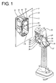
- FIG. 1 is a perspective view showing waiting-side housing and watertight connector housings before connection,
- FIG. 2 is a side view partly in section of the waiting-side and watertight connector housings before the connection,
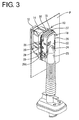
- FIG. 3 is a perspective view of the waiting-side and watertight connector housings when being properly connected,
- FIG. 4 is a side view partly in section of the waiting-side and watertight connector housings when being properly connected with a portion near a sealing portion partially enlargedly shown,
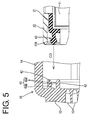
- FIG. 5 is a fragmentary side sectional views enlargedly showing an engaging portion and a sealing portion according to the second embodiment before connection,
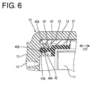
- FIG. 6 is a fragmentary view enlargedly showing the engaging portion and the sealing portion according to the second embodiment at the time of proper connection, and
- FIG. 7 is a side view partly in section of prior art waiting-side and watertight connector housings.
-
- A first preferred embodiment of the present invention is described with reference to FIGS. 1 to 4.
- A connector of this embodiment is comprised of a receiving or waiting-side or first connector housing 10 (hereinafter, referred to as a waiting-side housing 10) and a watertight or second connector housing 11 (hereinafter, referred to as watertight housing 11) which are connectable with each other along a connecting direction CD. It should be noted that, in the following description, engaging end sides or mating sides of the waiting-side and
watertight housings - The waiting-
side housing 10 is constructed such that one or more, preferably a plurality of male terminals (not shown) are or can be at least partly accommodated in one ormore cavities 13 formed in amain body 12 thereof, and tabs of the male terminals at least partly project into areceptacle 14. Aflange portion 15 is provided at at least part of the outer circumferential surface of the leading end of thereceptacle 14. A ring-shaped rubber or resilient sealingmember 16 for a mount opening Pa is mounted or mountable on the front surface of theflange portion 15. In order to mount the waiting-side housing 10 onto a panel P, the leading end of thereceptacle 14 is at least partly inserted or mountable into the mount opening Pa formed in the panel P, an engagingclaw 17 provided at the upper end of thereceptacle 14 is engaged or engageable with the upper edge of the mount opening Pa, and aresilient locking claw 17A provided at the lower end of thereceptacle 14 is engaged or engageable with the lower edge of the mount opening Pa while being resiliently deformed. Then, the sealingmember 16 is substantially closely brought or bringable into contact preferably with the substantially entire circumferential edge of the mount opening Pa, and the panel P and the waiting-side housing 10 are connected with each other while sealing is provided therebetween. - With the waiting-
side housing 10 mounted on the panel P, thereceptacle 14 is open along the opening edge of or at the mount opening Pa, and thewatertight housing 11 at least partly enters thereceptacle 14 through anopening portion 14A and is connected with the waiting-side housing 10. Further, a pair ofcam followers 19, which preferably are pins concentric with each other, project at the left and right inner surfaces of thereceptacle 14. - The
watertight housing 11 is formed with one or more cavities (not shown) for at least partly accommodating one or more, preferably a plurality of female terminals (not shown) therein, and is provided with agrommet 21 made of a rubber or other resilient material which is so mounted from behind as to cover all the outer surfaces of thewatertight housing 11 excluding the front surface and agrommet cover 22 made preferably of a hard or shape-maintaining resin to preferably cover the substantially whole body of thegrommet 21 excluding the front surface from the back side of thegrommet 21. A wire draw-outportion 23 preferably in the form of a tube through which a bundle of wires connected with the female terminals are to be inserted or insertable is provided at the back surface of thegrommet 21. On the other hand, a throughhole 24 is formed in the back surface of thegrommet cover 22 for avoiding the wire draw-outportion 23, and a pair of shaft pins 25 project at the left and right or lateral outer surfaces of thegrommet cover 22. - A substantially U-shaped lever 18 (as a preferably moving means) is so mounted on the
grommet cover 22 as to cross over or bridge or span thegrommet cover 22. Thelever 18 is comprised of a pair ofoperation arms 26 and anoperable portion 27 coupling theoperation arms 26 with each other preferably at their leading ends. Eachoperation arm 26 is formed with abearing hole 28 to be engaged with the correspondingshaft pin 25. Thelever 18 is rotatable or pivotable about these engaged portions between a (first) position where thelever 18 is substantially located before a connecting operation (see FIG. 2) and a (second) position where the lever is substantially located after (see FIG. 4) the connecting operation. - Each
operation arm 26 is formed with acam groove 29 substantially corresponding to thecam follower 19 around the bearinghole 28 in a converging manner toward the bearinghole 28, e.g. spiral-like. One end of eachcam groove 29 serves as a receivingportion 29A for receiving and engaging thecam follower 19 when thewatertight housing 11 is at least partly fitted or inserted into thereceptacle 14. The engagedcam followers 19 are displaced along thecam grooves 29 as theoperation arms 26 are rotated, thereby pulling thewatertight housing 11 into thereceptacle 14. - A squeezing
wall 30 is annularly formed at the back end of thereceptacle 14 of the waiting-side housing 10 preferably so as to surround the front side of themain body 12 of the waiting-side housing 10. The squeezingwall 30 is substantially concentrically provided within thereceptacle 14 so as to be arranged radially inwardly from the outer portion of thereceptacle 14. - On the other hand, the
grommet 21 is mounted such that the inner surface thereof is or can be held substantially in close contact with the outer surfaces of thewatertight housing 11. The front end of thegrommet 21 extends to such a position as to be preferably substantially in flush with the leading end of thewatertight housing 11. A sealingportion 31 is provided at a portion of the leading end of thegrommet 21 which is to overlap the squeezingwall 30 of the waiting-side housing 10 along the connecting direction CD when thehousings grommet cover 22 which is to overlap along the connecting direction CD the sealingportion 31 is slightly thinned (or its thickness in radial direction is reduced), and a clearance into which the squeezingwall 30 is fittable is defined between the sealingportion 31 and thegrommet cover 22. In other words, when theconnector housings receptacle 14, the thinned portion of thegrommet cover 22, the squeezingwall 30, the sealingportion 31 and a part of themain body 11 overlap along the longitudinal direction or along the connecting direction CD in this order from the other side to the inner side (see FIG. 4) and the distances between the squeezingwall 30 and the part of themain body 11 is set such that the sealingportion 31 is compressed therein in radial direction or in a direction substantially normal to the connecting direction CD. - One or more, preferably two
lip portions 31A are circumferentially formed on each of the inner and/or outer circumferential surfaces of the sealingportion 31. A spacing between peaks of theouter lip portions 31A and the inner circumferential surface of thegrommet cover 22 is set to be smaller than the thickness or radial position of the squeezingwall 30, so that thelip portions 31A are compressed in directions substantially normal to a connecting direction between the squeezingwall 30 and thewatertight housing 11 when the squeezingwall 30 is fitted into the above clearance between the thinned portion of thegrommet cover 22 and the sealingportion 31 thereby deflecting the sealing portion inwardly and compressing it between the squeezingwall 31 and the main body of thewatertight connector 11. - Next, the effects of the embodiment having the above construction are described.
- First, the
watertight housing 11 preferably substantially covered with thegrommet 21 and thegrommet cover 22 is at least partly fitted in the connecting direction CD into thereceptacle 14 of the waiting-side housing 10 mounted or mountable on the panel P with thelever 18 located at the position before the connecting operation as shown in FIG. 2. Then, thecam followers 19 at least partly enter the correspondingcam groves 29 through the receivingportions 29A of thecam grooves 29. When the lever 18 (as a preferred moving means) is operated (rotated or pivoted) in this state, thecam followers 19 are displaced along thecam grooves 29 as theoperation arms 26 are rotated or pivoted, thereby pulling thewatertight housing 11 into thereceptacle 14. Shortly, thelever 18 is rotated or pivoted to the position after the connecting operation as shown in FIG. 4, thereby substantially completing the connection of thehousings wall 30 is fitted in an area between the sealingportion 31 and thegrommet cover 22, and thelip portions 31A are compressed in directions substantially normal to the connecting direction CD of theconnector housings wall 30 and the outer circumferential surface of thewatertight housing 11. In other words, the squeezingwall 30, the sealingportion 31 and thegrommet cover 22 are radially arranged (or arranged substantially normal to the connecting direction CD) with respect to each other at such a distance so as to resiliently compress the sealingportion 30 in the direction substantially normal to the connecting direction CD. Therefore, the sealingportion 31 is watertightly or sealingly kept substantially in close contact with the inner circumferential surface of the squeezingwall 30 and the outer circumferential surface of thewatertight housing 11, thereby providing sealing between the bothhousings - In order to stably provide sealing between the two
housings portion 31 needs to be constantly compressed by exerting a force of the same intensity in the directions of compression of the sealingportion 31 to maintain a close contact state. If the sealingportion 31 is compressed in the directions at an angle comprises between about 70° and about 110° (i.e. substantially normal) to the connecting direction CD by the squeezingwall 30 as in this embodiment, the front end of the sealingportion 31 is substantially not compressed in or along the connecting direction CD since it does not come into contact with the back surface of thereceptacle 14. Even if the engaged shaft pins 25 and 28 should shake with respect to each other, thewatertight housing 11 is not displaced in separating direction from the waiting-side housing 10 since the sealingportion 31 exerts substantially no resilient force acting in the connecting direction CD on thewatertight housing 11. Even if thewatertight housing 11 should be moved in the separating direction (or a direction substantially opposite to the connecting direction CD), the sealingportion 31 is only moved backward along the squeezingwall 30 while being compressed. Therefore, there is no change in the compressed state of the sealingportion 31 in the directions substantially normal to the connecting direction CD, i.e. the close contact state of the outer circumferential surface of thewatertight housing 11 and the inner circumferential surface of the squeezingwall 30. Thus, sealing can be securely provided between thehousings - Further, the above effects can be obtained by defining the clearance between the sealing
portion 31 at the leading end of thegrommet 21 and thegrommet cover 22, and providing the squeezingwall 30 fittable into the clearance and projecting at the back end of thereceptacle 14. Therefore, the constructions of thehousings - Next, a second preferred embodiment of the present invention is described with reference to FIGS. 5 and 6.
- An engaging
portion 40 is formed at the back surface of areceptacle 14 by forming two annularly projecting squeezingwalls 42 at a specified (predetermined or predeterminable) spacing so as to doubly at least partly surround the front side of amain body 12 of a waiting-side housing 10. On the other hand, a sealingportion 43 in the form of a wall projects substantially in a connecting direction CD preferably over the substantially entire circumferential surface of the front end of agrommet 21. A leading end portion of the sealingportion 43 is formed into awatertight portion 43A preferably having a substantially elliptical cross section or other enlarged cross-section swollen in directions substantially normal to the connecting direction CD. - On the other hand, a distance between
opposed surfaces 40A of the engagingportions 40 is smaller than a radial dimension of thewatertight portion 43A along the direction substantially normal to the connecting direction CD. When thewatertight portion 43A is fitted into the engagingportion 40, thewatertight portion 43A is compressed in the directions substantially normal to the connecting direction CD between the substantially opposed or facingsurfaces 40A, and the leading end of thewatertight portion 43A is brought or bringable into close contact with aback surface 40B of the engagingportion 40. h Since the other construction is same as the first embodiment, no description is given thereon. Next, the effects of the second embodiment are described. - Similar to the first embodiment, a
watertight housing 11 is at least partly fitted into thereceptacle 14. As the sealingportion 43 is at least partly fitted into the engagingportion 40, thewatertight portion 43A is compressed in the directions substantially normal to the connecting direction CD between the opposite or facinginner surfaces 40A of the engagingportion 40. Finally, when the connection is substantially completed, the leading end of thewatertight portion 43A preferably is held substantially in close contact with theback surface 40B of the engagingportion 40. - As described above, in this embodiment, the
watertight portion 43A is compressed in the directions substantially normal to the engaging direction (being substantialy parallel to the connecting direction CD), thereby providing sealing between themain body 12 of the waiting-side housing 10 and thewatertight housing 11. In other words, thewatertight portion 43A is at least partly fitted into the groove or recess defined by the oppositeinner surfaces 40A thereby being compressed in a direction substantially normal to the fitting direction (being substantialy parallel to the connecting direction CD), as the readial dimension or thickness of the resilientwatertight portion 43A is set to be greater than the radial distance between the oppositeinner surfaces 40A. Thus, the same effects as the first embodiment can be obtained. In addition, since thewatertight portion 43A is or can be preferably held substantially in close contact with three surfaces, i.e. the oppositeinner surfaces 40A and theback surface 40B of the engagingportion 40 in the second embodiment, sealing can be more securely provided between thehousings - Accordingly, to provide a connector in which sealing can be securely provided between waiting-side and watertight connector housings, a squeezing
wall 30 fittable into a clearance between the leading ends of agrommet 21 and agrommet cover 22 mounted on awatertight housing 11 is provided at the back end of areceptacle 14 of a waiting-side housing 10. A sealingportion 31 havinglip portions 31A is formed at a portion of thegrommet 21 which is to overlap the squeezingwall 30 when thehousings lip portions 31A are compressed in directions normal to a connecting direction between the squeezingwall 30 and thewatertight housing 11 during a connecting operation, thereby providing sealing between thehousings - The present invention is not limited by the above described and illustrated embodiments. For example, following embodiments are also embraced by the technical scope of the present invention as defined in the claims. Beside the following embodiments, various changes can be made without departing from the scope and spirit of the present invention as defined in the claims.
- (1) According to the second embodiment, the sealing portion is held in close contact with the back surface of the engaging portion as well as the opposite inner surfaces when being fitted into the engaging portion. However, the sealing portion may not be or only partly held in in close contact with the back surface.
- (2) Although the sealing portion has a substantially elliptical cross section in the second embodiment, the shape of the sealing portion may be changed provided that it is compressed in the directions substantially normal to the connecting direction CD by the engaging portion.
- (3) According to the second embodiment, the sealing portion in the formed of a projecting wall is provided at the grommet, and the engaging portion in the form of a groove is provided at the waiting-side housing. However, the grommet may be provided with a groove-shaped sealing portion, the waiting-side housing may be provided with an engaging portion engageable with such a sealing portion, and the sealing portion may be compressed in the directions substantially normal to the connecting direction CD by the engaging portion so as to provide sealing.
- (4) Even though in the preceding embodiments the movable member has been described wit reference to a lever pivotably or rotatably provided on the watertight connector, it should be understood that any other movable member such as a substantially linearly movable member may be used for displaying a cam action so as to connect or assist the connection of the connector housings.
-
-
- 10
- waiting-side connector housing
- 11
- watertight connector housing
- 18
- lever
- 19
- cam follower
- 21
- grommet
- 29
- cam groove
- 31
- sealing portion
- 31A
- lip portion
- 40
- engaging portion
- 43A
- watertight portion
- P
- panel
Claims (11)
- A connector, comprising a first connector housing (10) mountable onto a panel (P) and a second connector housing (11) engageable with the first connector housing (10),
wherein:the second connector housing (11) is provided with a grommet (21) for substantially covering the second connector housing (11), andthe grommet (21) is formed with at least one sealing portion (31; 43) for providing sealing between the connector housings (10, 11) by being compressed in directions substantially normal to a connecting direction (CD) when the first connector housing (10) and the second connector housing (11) are connected with each other. - A connector according to claim 1, wherein the sealing portion (31; 43) is at least partly radially arranged between the first connector housing (10) and the second connector housing (11) thereby being compressed in directions substantially normal to the connecting direction (CD).
- A connector according to one or more of the preceding claims, wherein a movable member (18) is provided on one of the first and second connector housings (10, 11) for displaying a cam action in order to connect the first and second connector housings (10, 11) with each other.
- A connector according to claim 3, wherein the movable member (18) comprises a lever (18) formed with at least one cam groove (29),
the lever (18) being provided on one (11) of the connector housings (10, 11) and the other one (10) of the connector housings (10, 11) is provided with at least one cam follower (19) engageable with the cam groove(s) (29),
the cam follower (19) is displaced along the cam groove (29) as the lever (18) is rotated, thereby connecting and separating the second connector housing (11) with and from the first connector housing (10). - A connector according to one or more of the preceding claims, wherein the sealing portion (31; 43) is formed at such a position as to be squeezed between surfaces (30, 11) of the connector housings substantially opposed to each other in the directions substantially normal to the connecting direction (CD) of the connector housings (10, 11).
- A connector according to one or more of the preceding claims, wherein the sealing portion (31; 43) comprises a portion (43) in the form of a projecting wall and/or a groove which is circumferentially formed on or in a surface of the grommet (21) preferably substantially opposed to a surface of the first connector housing (10) along the connecting direction (CD) of the connector housings (10, 11), an engaging portion (40) engageable with the sealing portion (43) in the form of a groove and/or a projecting wall is circumferentially formed preferably in or on the surface of the first connector housing (10) substantially opposed to the surface of the grommet (21), and the sealing portion (43) can be compressed against the circumferential surface of the engaging portion (40) in the directions substantially normal to the connecting direction (CD) of the connector housings (10, 11).
- A connector according to claim 6, wherein the sealing portion (43) comes substantially into engagement with the engaging portion (40) both in a direction along the connecting direction (CD) and in the directions substantially normal to the connecting direction (CD) of the connector housings (10, 11).
- A connector according to one or more of the preceding claims, wherein the second connector housing (11) is provided with a grommet cover (22) for at least partly covering the grommet (21), wherein in the properly connected state of the connector housings (10, 11) a main body of the second connector housing (11), the sealing portion (31), a portion (30) of the first connector housing (10) and a portion of the grommet cover (22) are radially arranged with respect to each other in this order.
- A method of assembling a watertight connector, comprising a first connector housing (10) mountable onto a panel (P) and a second connector housing (11) engageable with the first connector housing (10),
wherein:providing the second connector housing (11) with a grommet (21) for substantially covering the second connector housing (11), andconnecting the first and second housings (10, 11) thereby compressing at least one sealing portion (31; 43) of the grommet (21) in directions substantially normal to a connecting direction (CD) of the connector housings (10, 11) for providing sealing between the connector housings (10, 11). - A method according to claim 9, wherein the step of compressing the sealing portion (31; 43) comprises the step of arranging the sealing portion (31; 43) at least partly radially between the first connector housing (10) and the second connector housing (11) thereby compressing the sealing portion (31; 43) in directions substantially normal to the connecting direction (CD).
- A method according to claim 9 or 10, wherein the connector housings (10, 11) are at least partly connected with each other by operating a movable member (18) provided on one of the first and second connector housings (10, 11) thereby displaying a cam action in order to connect the first and second connector housings (10,11) with each other.
Applications Claiming Priority (2)
| Application Number | Priority Date | Filing Date | Title |
|---|---|---|---|
| JP2001372844 | 2001-12-06 | ||
| JP2001372844A JP3991670B2 (en) | 2001-12-06 | 2001-12-06 | connector |
Publications (2)
| Publication Number | Publication Date |
|---|---|
| EP1318570A1 true EP1318570A1 (en) | 2003-06-11 |
| EP1318570B1 EP1318570B1 (en) | 2005-04-13 |
Family
ID=19181661
Family Applications (1)
| Application Number | Title | Priority Date | Filing Date |
|---|---|---|---|
| EP02027507A Expired - Lifetime EP1318570B1 (en) | 2001-12-06 | 2002-12-05 | A connector and method of assembling it |
Country Status (4)
| Country | Link |
|---|---|
| US (1) | US6685496B2 (en) |
| EP (1) | EP1318570B1 (en) |
| JP (1) | JP3991670B2 (en) |
| DE (1) | DE60203685T2 (en) |
Cited By (8)
| Publication number | Priority date | Publication date | Assignee | Title |
|---|---|---|---|---|
| WO2005101583A1 (en) * | 2004-04-07 | 2005-10-27 | Tyco Electronics Amp Gmbh | Sealed plug-in connection that runs through a dividing wall and corresponding mounting method |
| GB2439410A (en) * | 2006-06-20 | 2007-12-27 | Yazaki Corp | Lever-type electric connector |
| WO2010060591A1 (en) * | 2008-11-27 | 2010-06-03 | Amphenol-Tuchel Electronics Gmbh | Electric partition feedthrough |
| WO2012085681A1 (en) | 2010-12-23 | 2012-06-28 | Fci Automotive Holding | Water proof connector assembly |
| EP1936757A3 (en) * | 2006-12-22 | 2012-11-28 | Weidmüller Interface GmbH & Co. KG | Connector system for wall mounting |
| EP3382820A1 (en) * | 2017-03-31 | 2018-10-03 | Tyco Electronics Japan G.K. | Seal member and electrical connector |
| IT201800002675A1 (en) * | 2018-02-14 | 2019-08-14 | Tyco Electronics Amp Italia Srl | Electrical connection device |
| CN116409452A (en) * | 2023-04-10 | 2023-07-11 | 南京全信传输科技股份有限公司 | Seabed power communication pressure-resistant cabin with adjustable function and disassembly and assembly method |
Families Citing this family (35)
| Publication number | Priority date | Publication date | Assignee | Title |
|---|---|---|---|---|
| JP3882111B2 (en) * | 2002-04-22 | 2007-02-14 | 住友電装株式会社 | Lever type connector |
| EP1450447B1 (en) * | 2003-02-18 | 2012-03-28 | Calsonic Kansei Corporation | Connector structure |
| JP2006221920A (en) | 2005-02-09 | 2006-08-24 | Sumitomo Wiring Syst Ltd | Connector |
| JP2008536277A (en) * | 2005-04-11 | 2008-09-04 | エフシーアイ | Grommet for electrical connector and electrical connector equipped with such grommet |
| JP2007149420A (en) * | 2005-11-25 | 2007-06-14 | Yazaki Corp | Lever fitting type connector |
| JP4761990B2 (en) * | 2006-02-06 | 2011-08-31 | 矢崎総業株式会社 | Waterproof connector |
| JP4697061B2 (en) * | 2006-06-15 | 2011-06-08 | 住友電装株式会社 | connector |
| DE602006013317D1 (en) * | 2006-09-21 | 2010-05-12 | Molex Inc | Lever-type electrical connector |
| JP2008108487A (en) * | 2006-10-24 | 2008-05-08 | Sumitomo Wiring Syst Ltd | Connector |
| JP5013336B2 (en) * | 2008-02-12 | 2012-08-29 | 矢崎総業株式会社 | LIF connector for body panel fixing |
| JP5056551B2 (en) * | 2008-04-07 | 2012-10-24 | 住友電装株式会社 | Grommet mounting structure |
| DE102009003103B4 (en) * | 2009-05-14 | 2011-03-24 | Tyco Electronics Ukraine Ltd. | Electrical connector |
| JP5565054B2 (en) * | 2010-04-07 | 2014-08-06 | 住友電装株式会社 | connector |
| JP5091983B2 (en) * | 2010-06-16 | 2012-12-05 | 矢崎総業株式会社 | Lever fitting type connector |
| CN102347562A (en) * | 2010-07-30 | 2012-02-08 | 鸿富锦精密工业(深圳)有限公司 | Connector |
| JP5653246B2 (en) * | 2011-02-15 | 2015-01-14 | 矢崎総業株式会社 | Lever type connector |
| DE102012112353A1 (en) * | 2012-12-17 | 2014-06-18 | Harting Electric Gmbh & Co. Kg | Car charger plug |
| DE202012104999U1 (en) * | 2012-12-20 | 2014-04-01 | Weidmüller Interface GmbH & Co. KG | adapter assembly |
| JP5904414B2 (en) * | 2013-05-13 | 2016-04-13 | 住友電装株式会社 | Waterproof connector |
| JP6537805B2 (en) * | 2014-10-29 | 2019-07-03 | 日本航空電子工業株式会社 | Lever type connector |
| DE102016201385B3 (en) * | 2016-01-29 | 2017-07-27 | Robert Bosch Gmbh | Electrical plug connection |
| EP3593416B1 (en) * | 2017-03-08 | 2022-08-31 | HARTING (Zhuhai) Manufacturing Co., LTD. | Connector assembly |
| JP6708160B2 (en) * | 2017-04-18 | 2020-06-10 | 住友電装株式会社 | connector |
| JP6924386B2 (en) * | 2018-01-25 | 2021-08-25 | 住友電装株式会社 | Lever type connector |
| DE102018203967A1 (en) * | 2018-03-15 | 2019-09-19 | Bayerische Motoren Werke Aktiengesellschaft | Charging terminal of a vehicle |
| WO2020036152A1 (en) * | 2018-08-17 | 2020-02-20 | 矢崎総業株式会社 | Lever-type connector |
| JP6970064B2 (en) * | 2018-08-30 | 2021-11-24 | 矢崎総業株式会社 | Grommet |
| JP7032351B2 (en) * | 2019-04-18 | 2022-03-08 | 矢崎総業株式会社 | Connector with grommet |
| JP7235599B2 (en) * | 2019-06-06 | 2023-03-08 | 矢崎総業株式会社 | connector |
| JP7230753B2 (en) * | 2019-09-26 | 2023-03-01 | 住友電装株式会社 | connector |
| JP7353716B2 (en) * | 2019-11-20 | 2023-10-02 | 矢崎総業株式会社 | connector structure |
| CA3173691A1 (en) * | 2020-04-22 | 2021-10-28 | Sebastien Geoffroy | Pass-through connector for a battery pack, battery pack, and method for introducing at least one gas in a hermetically sealable casing for a battery pack |
| JP7505368B2 (en) * | 2020-10-28 | 2024-06-25 | 住友電装株式会社 | Grommet |
| JP2022129693A (en) | 2021-02-25 | 2022-09-06 | 住友電装株式会社 | panel mount connector |
| JP7533362B2 (en) * | 2021-05-28 | 2024-08-14 | 住友電装株式会社 | connector |
Citations (3)
| Publication number | Priority date | Publication date | Assignee | Title |
|---|---|---|---|---|
| EP0913891A2 (en) * | 1997-10-01 | 1999-05-06 | Sumitomo Wiring Systems, Ltd. | Electrical connector |
| EP1032085A2 (en) * | 1995-04-07 | 2000-08-30 | Sumitomo Wiring Systems, Ltd. | Lever type connector |
| EP1150393A2 (en) * | 2000-04-25 | 2001-10-31 | Sumitomo Wiring Systems, Ltd. | Connector |
Family Cites Families (2)
| Publication number | Priority date | Publication date | Assignee | Title |
|---|---|---|---|---|
| US5971791A (en) * | 1996-08-30 | 1999-10-26 | Kansei Corporation | Waterproof connector |
| US6305957B1 (en) * | 2000-02-24 | 2001-10-23 | Delphi Technologies, Inc. | Electrical connector assembly |
-
2001
- 2001-12-06 JP JP2001372844A patent/JP3991670B2/en not_active Expired - Fee Related
-
2002
- 2002-12-02 US US10/307,823 patent/US6685496B2/en not_active Expired - Fee Related
- 2002-12-05 DE DE60203685T patent/DE60203685T2/en not_active Expired - Lifetime
- 2002-12-05 EP EP02027507A patent/EP1318570B1/en not_active Expired - Lifetime
Patent Citations (3)
| Publication number | Priority date | Publication date | Assignee | Title |
|---|---|---|---|---|
| EP1032085A2 (en) * | 1995-04-07 | 2000-08-30 | Sumitomo Wiring Systems, Ltd. | Lever type connector |
| EP0913891A2 (en) * | 1997-10-01 | 1999-05-06 | Sumitomo Wiring Systems, Ltd. | Electrical connector |
| EP1150393A2 (en) * | 2000-04-25 | 2001-10-31 | Sumitomo Wiring Systems, Ltd. | Connector |
Cited By (18)
| Publication number | Priority date | Publication date | Assignee | Title |
|---|---|---|---|---|
| WO2005101583A1 (en) * | 2004-04-07 | 2005-10-27 | Tyco Electronics Amp Gmbh | Sealed plug-in connection that runs through a dividing wall and corresponding mounting method |
| DE102004017275A1 (en) * | 2004-04-07 | 2005-10-27 | Tyco Electronics Amp Gmbh | Sealed plug-in connection through a partition and mounting method |
| CN100514762C (en) * | 2004-04-07 | 2009-07-15 | 泰科电子Amp有限责任公司 | Sealed plug-in connection that runs through a dividing wall and corresponding mounting method |
| US7704086B2 (en) | 2004-04-07 | 2010-04-27 | Tyco Electronics Amp Gmbh | Sealed plug connection through a partition wall and method of fitting |
| GB2439410A (en) * | 2006-06-20 | 2007-12-27 | Yazaki Corp | Lever-type electric connector |
| US7708573B2 (en) | 2006-06-20 | 2010-05-04 | Yazaki Corporation | Connector |
| GB2439410B (en) * | 2006-06-20 | 2011-07-13 | Yazaki Corp | Connector |
| EP1936757A3 (en) * | 2006-12-22 | 2012-11-28 | Weidmüller Interface GmbH & Co. KG | Connector system for wall mounting |
| CN102217144A (en) * | 2008-11-27 | 2011-10-12 | 安费诺-图赫尔电子有限责任公司 | Electric partition feedthrough |
| WO2010060591A1 (en) * | 2008-11-27 | 2010-06-03 | Amphenol-Tuchel Electronics Gmbh | Electric partition feedthrough |
| US9006588B2 (en) | 2008-11-27 | 2015-04-14 | Amphenol-Tuchel Electronics Gmbh | Electric partition feedthrough |
| WO2012085681A1 (en) | 2010-12-23 | 2012-06-28 | Fci Automotive Holding | Water proof connector assembly |
| EP3382820A1 (en) * | 2017-03-31 | 2018-10-03 | Tyco Electronics Japan G.K. | Seal member and electrical connector |
| US10367292B2 (en) | 2017-03-31 | 2019-07-30 | Tyco Electronics Japan G.K. | Seal member and electrical connector |
| IT201800002675A1 (en) * | 2018-02-14 | 2019-08-14 | Tyco Electronics Amp Italia Srl | Electrical connection device |
| US10873151B2 (en) | 2018-02-14 | 2020-12-22 | TE Connectivity Italia Distribution S.r.l. | Electrical connection device with seal between a protection device and a connector |
| CN116409452A (en) * | 2023-04-10 | 2023-07-11 | 南京全信传输科技股份有限公司 | Seabed power communication pressure-resistant cabin with adjustable function and disassembly and assembly method |
| CN116409452B (en) * | 2023-04-10 | 2024-04-23 | 南京全信传输科技股份有限公司 | Seabed power communication pressure-resistant cabin with adjustable function and disassembly and assembly method |
Also Published As
| Publication number | Publication date |
|---|---|
| JP2003173837A (en) | 2003-06-20 |
| US20030109166A1 (en) | 2003-06-12 |
| EP1318570B1 (en) | 2005-04-13 |
| DE60203685D1 (en) | 2005-05-19 |
| DE60203685T2 (en) | 2006-03-02 |
| JP3991670B2 (en) | 2007-10-17 |
| US6685496B2 (en) | 2004-02-03 |
Similar Documents
| Publication | Publication Date | Title |
|---|---|---|
| EP1318570A1 (en) | A connector and method of assembling it | |
| EP2075880B1 (en) | Lever-type connector, connector assembly and connecting method | |
| US6364681B1 (en) | Connector assembly and method of mounting same | |
| US7520765B2 (en) | Connector and connector assembly of the movable member type | |
| EP1211757B1 (en) | Elektrical connector | |
| EP1737078B1 (en) | A connector and a connector assembly method | |
| US7104831B2 (en) | Connector | |
| US7722381B2 (en) | Connector | |
| US7252547B2 (en) | Connector | |
| EP1672747B1 (en) | A connector | |
| EP1830436B1 (en) | A connector, connector assembly and assembling method | |
| JP4489217B2 (en) | Connector with lever | |
| EP1830435B1 (en) | A lever-type connector and connector assembly | |
| EP1137111B1 (en) | A watertight connector and sealing member | |
| JP2002329554A (en) | Connector | |
| JP2002329548A (en) | Connector | |
| US6793513B2 (en) | Connector with an inertial locking function | |
| US6623286B2 (en) | Lever-type connector | |
| US5564953A (en) | Divided-type multi-pole connector | |
| EP1587174B1 (en) | A connector and a connector assembly | |
| JP2929412B2 (en) | Lever connector | |
| US20030216071A1 (en) | Connector having an operable member and a method of assembling such a connector | |
| JP2007059153A (en) | Connector | |
| JP2022181590A (en) | Connector with lever and connector system comprising connector with lever | |
| JPH0448561A (en) | Electrical connector |
Legal Events
| Date | Code | Title | Description |
|---|---|---|---|
| PUAI | Public reference made under article 153(3) epc to a published international application that has entered the european phase |
Free format text: ORIGINAL CODE: 0009012 |
|
| AK | Designated contracting states |
Designated state(s): AT BE BG CH CY CZ DE DK EE ES FI FR GB GR IE IT LI LU MC NL PT SE SI SK TR |
|
| AX | Request for extension of the european patent |
Extension state: AL LT LV MK RO |
|
| 17P | Request for examination filed |
Effective date: 20030717 |
|
| 17Q | First examination report despatched |
Effective date: 20031008 |
|
| AKX | Designation fees paid |
Designated state(s): DE FR |
|
| GRAP | Despatch of communication of intention to grant a patent |
Free format text: ORIGINAL CODE: EPIDOSNIGR1 |
|
| GRAS | Grant fee paid |
Free format text: ORIGINAL CODE: EPIDOSNIGR3 |
|
| GRAA | (expected) grant |
Free format text: ORIGINAL CODE: 0009210 |
|
| AK | Designated contracting states |
Kind code of ref document: B1 Designated state(s): DE FR |
|
| REF | Corresponds to: |
Ref document number: 60203685 Country of ref document: DE Date of ref document: 20050519 Kind code of ref document: P |
|
| ET | Fr: translation filed | ||
| PLBE | No opposition filed within time limit |
Free format text: ORIGINAL CODE: 0009261 |
|
| STAA | Information on the status of an ep patent application or granted ep patent |
Free format text: STATUS: NO OPPOSITION FILED WITHIN TIME LIMIT |
|
| 26N | No opposition filed |
Effective date: 20060116 |
|
| PGFP | Annual fee paid to national office [announced via postgrant information from national office to epo] |
Ref country code: DE Payment date: 20121128 Year of fee payment: 11 |
|
| PGFP | Annual fee paid to national office [announced via postgrant information from national office to epo] |
Ref country code: FR Payment date: 20130107 Year of fee payment: 11 |
|
| REG | Reference to a national code |
Ref country code: DE Ref legal event code: R119 Ref document number: 60203685 Country of ref document: DE |
|
| REG | Reference to a national code |
Ref country code: DE Ref legal event code: R119 Ref document number: 60203685 Country of ref document: DE Effective date: 20140701 |
|
| REG | Reference to a national code |
Ref country code: FR Ref legal event code: ST Effective date: 20140829 |
|
| PG25 | Lapsed in a contracting state [announced via postgrant information from national office to epo] |
Ref country code: DE Free format text: LAPSE BECAUSE OF NON-PAYMENT OF DUE FEES Effective date: 20140701 |
|
| PG25 | Lapsed in a contracting state [announced via postgrant information from national office to epo] |
Ref country code: FR Free format text: LAPSE BECAUSE OF NON-PAYMENT OF DUE FEES Effective date: 20131231 |