EP1318323A2 - Dispositif d'absorption d'énergie - Google Patents
Dispositif d'absorption d'énergie Download PDFInfo
- Publication number
- EP1318323A2 EP1318323A2 EP02292821A EP02292821A EP1318323A2 EP 1318323 A2 EP1318323 A2 EP 1318323A2 EP 02292821 A EP02292821 A EP 02292821A EP 02292821 A EP02292821 A EP 02292821A EP 1318323 A2 EP1318323 A2 EP 1318323A2
- Authority
- EP
- European Patent Office
- Prior art keywords
- absorber
- shell
- webs
- absorption device
- stack
- Prior art date
- Legal status (The legal status is an assumption and is not a legal conclusion. Google has not performed a legal analysis and makes no representation as to the accuracy of the status listed.)
- Granted
Links
Images


Classifications
-
- B—PERFORMING OPERATIONS; TRANSPORTING
- B60—VEHICLES IN GENERAL
- B60R—VEHICLES, VEHICLE FITTINGS, OR VEHICLE PARTS, NOT OTHERWISE PROVIDED FOR
- B60R19/00—Wheel guards; Radiator guards, e.g. grilles; Obstruction removers; Fittings damping bouncing force in collisions
- B60R19/02—Bumpers, i.e. impact receiving or absorbing members for protecting vehicles or fending off blows from other vehicles or objects
- B60R19/24—Arrangements for mounting bumpers on vehicles
- B60R19/26—Arrangements for mounting bumpers on vehicles comprising yieldable mounting means
- B60R19/34—Arrangements for mounting bumpers on vehicles comprising yieldable mounting means destroyed upon impact, e.g. one-shot type
-
- B—PERFORMING OPERATIONS; TRANSPORTING
- B60—VEHICLES IN GENERAL
- B60R—VEHICLES, VEHICLE FITTINGS, OR VEHICLE PARTS, NOT OTHERWISE PROVIDED FOR
- B60R19/00—Wheel guards; Radiator guards, e.g. grilles; Obstruction removers; Fittings damping bouncing force in collisions
- B60R19/02—Bumpers, i.e. impact receiving or absorbing members for protecting vehicles or fending off blows from other vehicles or objects
- B60R19/18—Bumpers, i.e. impact receiving or absorbing members for protecting vehicles or fending off blows from other vehicles or objects characterised by the cross-section; Means within the bumper to absorb impact
-
- F—MECHANICAL ENGINEERING; LIGHTING; HEATING; WEAPONS; BLASTING
- F16—ENGINEERING ELEMENTS AND UNITS; GENERAL MEASURES FOR PRODUCING AND MAINTAINING EFFECTIVE FUNCTIONING OF MACHINES OR INSTALLATIONS; THERMAL INSULATION IN GENERAL
- F16F—SPRINGS; SHOCK-ABSORBERS; MEANS FOR DAMPING VIBRATION
- F16F7/00—Vibration-dampers; Shock-absorbers
- F16F7/12—Vibration-dampers; Shock-absorbers using plastic deformation of members
- F16F7/121—Vibration-dampers; Shock-absorbers using plastic deformation of members the members having a cellular, e.g. honeycomb, structure
-
- B—PERFORMING OPERATIONS; TRANSPORTING
- B60—VEHICLES IN GENERAL
- B60R—VEHICLES, VEHICLE FITTINGS, OR VEHICLE PARTS, NOT OTHERWISE PROVIDED FOR
- B60R19/00—Wheel guards; Radiator guards, e.g. grilles; Obstruction removers; Fittings damping bouncing force in collisions
- B60R19/02—Bumpers, i.e. impact receiving or absorbing members for protecting vehicles or fending off blows from other vehicles or objects
- B60R19/18—Bumpers, i.e. impact receiving or absorbing members for protecting vehicles or fending off blows from other vehicles or objects characterised by the cross-section; Means within the bumper to absorb impact
- B60R2019/1806—Structural beams therefor, e.g. shock-absorbing
- B60R2019/1813—Structural beams therefor, e.g. shock-absorbing made of metal
- B60R2019/182—Structural beams therefor, e.g. shock-absorbing made of metal of light metal, e.g. extruded
-
- B—PERFORMING OPERATIONS; TRANSPORTING
- B60—VEHICLES IN GENERAL
- B60R—VEHICLES, VEHICLE FITTINGS, OR VEHICLE PARTS, NOT OTHERWISE PROVIDED FOR
- B60R19/00—Wheel guards; Radiator guards, e.g. grilles; Obstruction removers; Fittings damping bouncing force in collisions
- B60R19/02—Bumpers, i.e. impact receiving or absorbing members for protecting vehicles or fending off blows from other vehicles or objects
- B60R19/18—Bumpers, i.e. impact receiving or absorbing members for protecting vehicles or fending off blows from other vehicles or objects characterised by the cross-section; Means within the bumper to absorb impact
- B60R2019/186—Additional energy absorbing means supported on bumber beams, e.g. cellular structures or material
-
- B—PERFORMING OPERATIONS; TRANSPORTING
- B60—VEHICLES IN GENERAL
- B60R—VEHICLES, VEHICLE FITTINGS, OR VEHICLE PARTS, NOT OTHERWISE PROVIDED FOR
- B60R19/00—Wheel guards; Radiator guards, e.g. grilles; Obstruction removers; Fittings damping bouncing force in collisions
- B60R19/02—Bumpers, i.e. impact receiving or absorbing members for protecting vehicles or fending off blows from other vehicles or objects
- B60R19/18—Bumpers, i.e. impact receiving or absorbing members for protecting vehicles or fending off blows from other vehicles or objects characterised by the cross-section; Means within the bumper to absorb impact
- B60R2019/1886—Bumper fascias and fastening means therefor
Definitions
- the present invention relates to systems of kinetic energy absorption, in particular usable to absorb the shock between a motor vehicle and a obstacle.
- the invention relates, according to a first of its aspects, an absorption device kinetic energy formed of a stack comprising a rigid beam extending in one dimension longitudinal, an absorber covering the beam, and a outer shell covering at least partially the absorber, the stack having, in a section transverse to the longitudinal dimension, a thickness extending along a longitudinal plane median of the beam and a width extending transverse to this median longitudinal plane, and this device undergoing, in response to an intensity shock greater than a determined minimum value, applied to the shell and directed towards the beam, deformations of the shell and the absorber resulting in particular by compression of the stack according to its thickness.
- the invention fits into this context, but more specifically pursues the goal of proposing a kinetic energy absorption device capable to equip any mobile, and allowing preserve the integrity of a fragile obstacle as much as possible that this mobile could meet at relatively high speed scaled down.
- the energy absorption device kinetics of the invention is essentially characterized in that the shell and the absorber are made of materials elastically deformable, in that each element of the stack formed separately by the beam, the absorber and the shell have a first veil, a second veil, and a base, in that the absorber and the shell define respective free volumes in which respectively register the beam and the absorber, the bases being stacked according to the thickness of the stack, the first sails being stacked along the width of the stack, on a first side of the median longitudinal plane, and the second sails being stacked along the width of the stack, a second side of the median longitudinal plane, in that the first and second absorber sails have first and second respective edges by which these sails are respectively attached to the first and second sails of the beam, in that the base of the absorber is spaced from the base of the beam according to the thickness of the stack, in that the shell sails are spaced from sails of the absorber
- the shell is fixed by its base to the base of the absorber.
- the free volume defined by the absorber is preferably convex, the two sails of the absorber having, in cross section, concavities respective facing this free volume.
- the absorption device of the invention can include spacing means arranged between the first veil of the absorber and the first veil of the shell.
- spacing means include for example spacers and a crosspiece, the spacers being fixed to the absorber and extending towards the first veil of the shell, and the crosspiece connecting the spacers to distance from the absorber and providing support for the first shell veil.
- first and second sails of the beam have first and second respective edges, distant from the base of beam and extending in directions opposite transverse
- first and second sails of the absorber have first and second edges respective, distant from the base of the absorber and extending in opposite transverse directions, respectively opposite the first and second edges of the beam
- the absorber is fixed to the beam by fixing the edges of the absorber to the edges beam correspondents.
- the spacers can then rest on the first beam of the beam, be attached to the first edge of the absorber, and cross the notches practiced in the first veil of the absorber.
- the first and second sails of the beam can diverge from each other from the base of this beam.
- first and second sails of the beam can also be respectively covered by the first and second sails of the absorber in first and second overlap areas respectively defined at the edge of the first and second sails of the absorber, the absorber being fixed to the beam by fixing of the first and second overlap zones on the first and second sails of the beam.
- the spacers are advantageously attached to the first absorber veil in the first overlap area, the first and second sails of the beam which can be substantially parallel to each other the other.
- the absorber and the shell can be made in a polymer, such as polypropylene, and formed by injection.
- the absorber has a module of Young between 750 and 1250 MPa, the sails of the absorber having for example a thickness included between 2 and 5 millimeters.
- the absorber is preferably curved, that is, it has a maximum thickness in a median transverse plane of the stack and gradually decreasing at increasing distance from this plan.
- the absorber can also form a hollow body, in which case the two sails of the absorber are by example connected, at a distance from the base, by two walls internal connected by a bottom, the free volume defined by the absorber being delimited by the internal walls and the background.
- the absorber thus formed can be produced in a polymer, such as polypropylene, and be formed by blowing.
- the shell is preferably fixed on the base of the absorber by reversible fixing means, such as as clipping means.
- the absorption device of the invention can be applied to the production of a vehicle bumper automotive, the beam being integral with the chassis of the vehicle and extending in a horizontal direction.
- this device has a compressive force substantially constant of the stack formed by the shell, absorber and beam, in a whole range of elastic compression of this stack, the beam forming a reference element which does not undergo itself that a completely negligible elastic compression.
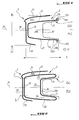
- the invention relates to a kinetic energy absorption device formed of a stack comprising ( Figures 1 to 3) a rigid beam 1, an absorber 2, and an outer shell 3.
- the rigid beam 1 typically made of steel, has an elongated shape and therefore extends in a longitudinal dimension L1.
- the absorber 2 covers the beam 1, and the shell external 3 itself covers the absorber 2, at least partially.
- the stack has, in its cross section, a thickness E, which extends parallel to the median longitudinal plane PL of the beam, and a width L2 which extends transverse to the median longitudinal plane PL.
- this device When it receives a shock of sufficient intensity, applied to the shell 3 and directed towards the beam 1, this device undergoes deformations of the shell 3 and absorber 2, which results in at least one compression of the stack according to its thickness E.
- the shell 3 and the absorber 2 are made of elastic materials deformable.
- the absorber 2 and the shell 3 can be made of a polymer, such as polypropylene.
- the absorber 2 preferably has a module of Young between 750 and 1250 MPa, typically of around 1000 MPa, and a thickness of material included between 2 and 5 millimeters, typically of the order of 3 millimeters.
- the absorber 2 defines a free volume 200 in which fits beam 1, and shell 3 defines a free volume 300 in which the absorber 2 is inscribed.
- Base 10 of beam 1, base 20 of the absorber 2, and the base 30 of the shell 3 are stacked according to the thickness E of the stack.
- the upper web 11 of the beam 1, the web upper 21 of absorber 2, and upper veil 31 of the shell 3 are stacked along the width L2 of the stack, in the delimited upper half-space PL1 by the median longitudinal plane PL.
- the lower web 12 of the beam 1, the web lower 22 of absorber 2, and lower veil 32 of the shell 3 are stacked along the width L2 of the stack, in the demarcated lower half-space PL2 by the median longitudinal plane PL.
- the sails 21 and 22 of the absorber 2 have respective edges, 211 and 222, by which these sails 21 and 22 are respectively attached to the sails corresponding, 11 and 12, of beam 1.
- the base 20 of the absorber 2 is spaced from the base 10 of the beam 1 along the thickness E of the stack, while the sails 31 and 32 of the shell 3 are spaced from the webs 21 and 22 of the absorber 2 according to the width L2 of the stack.
- the shell 3 is fixed to the stack of so as to allow deformation of the base 30 of this shell in the median longitudinal plane PL, the base 30 of the shell 3 can thus be fixed to the base 20 of absorber 2, for example by means of members reversible snap fastening 5.
- the shell 3 thanks to the fact that it can deform elastically in the plane longitudinal median PL, watch, in a range determined, behavior close to behavior classic linear elastic.
- the absorber 2 shows meanwhile, in its range elastic behavior, more elastic behavior complex resulting from the fact that it deforms, under the effect shock, by compression then by buckling of its sails 21 and 22.
- the absorber 2 can thus take the position indicated by the reference 2 'in Figure 3 and illustrated in Figure 8.
- X0 where F2 is the force which the absorber 2 opposes to the shock, where X is the amplitude of the deformation which the absorber 2 undergoes, where X0 is the amplitude of the deformation undergone by the absorber 2 at the time when the sails 21 and 22 of the absorber flame, where k2 is the stiffness that the absorber exhibits before its sails burn, where k3 is the stiffness that the absorber exhibits after its sails have started to flame, and where ⁇ is a function taking a zero value before the buckling of the sails 21 and 22, the unit value after the buckling, and a value changing from zero to one during the buckling.
- the rounding presented by the experimental curve between the two line segments has a radius of curvature not constant, depending on multiple parameters.
- the absorber 2 and the shell 3 are mounted in parallel, in the mechanical sense of the term, so their resistance forces to the deformation are added.
- the device of the invention can therefore be dimensioned in such a way that the effort that he opposes its compression in the direction of its thickness E is limited to a value appreciably constant and independent of the magnitude of this compression, at least in its behavior range elastic.
- the free volume 200 defined by the absorber 2 is preferably convex, and shaped to so that the two sails 21 and 22 of the absorber 2 have, in cross section, concavities respectively facing this free volume 200.
- the veil upper 31 of the shell 3 is arranged and maintained at distance from the upper web 21 of the absorber 2 by means spacers 4, for example essentially constituted by spacers 41 and a crosspiece 42.
- the spacers 41 are fixed to the absorber 2 and extend towards the upper web 31 of the shell 3, while the crosspiece 42 connects the spacers 41 to each other at a distance from the absorber 2, and provides support for the upper web 31 of the shell 3.
- the upper and lower sails, 11 and 12, of the beam 1 have corresponding flanges, 111 and 122, spaced from base 10 of beam 1 and extending in opposite transverse directions.
- the upper and lower sails 21 and 22 of the absorber 2 have corresponding edges, 213 and 224, distant from base 20 of absorber 2 and extending in opposite transverse directions, respectively opposite the upper edges and lower, 111 and 122, of beam 1.
- This arrangement allows, in a simple way, to make the absorber 2 secured to the beam 1 by fixing the edges 213 and 224 of the absorber 2 on the edges correspondents 111 and 122 of beam 1.
- the spacers 41 are preferably supported on the upper web 11 of the beam 1 (FIG. 3), are fixed to the upper edge 213 of the absorber 2, and pass through notches 215 (fig. 4) made in the upper web 21 of absorber 2.
- the sails 11 and 12 of beam 1 can diverge from each other from the base 10 of this beam 1.
- FIG. 5 illustrates an embodiment in which the sails 11 and 12 of the beam 1 are substantially parallel to each other.
- This arrangement favors the possibility of planning that the sails 11 and 12 of the beam 1 are covered by the corresponding sails 21 and 22 of the absorber 2 in respective overlap zones, 217 and 226, defined at the edge of the corresponding sails 21 and 22 of the absorber 2.
- the absorber 2 has a variable thickness in the longitudinal plane median PL.
- Figure 7 illustrates different sections transverse C0 to C4 of absorber 2, in different corresponding points identified in Figure 6, these two figures showing that the absorber 2 has a maximum thickness in the transverse plane median PT of stacking, and gradually decreasing at increasing distance from this PT plane.
- the absorber is generally bent to follow the outer shape of the shell, which is more particularly the case when, as we will see below, the device of the invention is applied to the production of a vehicle bumper automobile, the shell then constituting the skin exterior of the bumper.
- the absorber 2 can be formed by injection of an appropriate polymer, such as than polypropylene, as already indicated above.
- the absorber 2 which can always consist of a polymer such as polypropylene, on the other hand, is more easily produced by blowing insofar as it forms a hollow body.
- the webs 21 and 22 of this absorber are connected, at a distance from the base 20, by two walls internal 23 and 24 connected by a bottom 25, the free volume 200 defined by the absorber 2 then being delimited by the internal walls 23, 24 and through the bottom 25.
- the absorption device of the invention can be applied to the production of a vehicle bumper automotive, the beam being integral with the chassis (not shown) of the vehicle and extending horizontally.
- the device of the invention makes it possible to make a bumper with an effort of controlled compression, for example substantially constant, throughout the elastic compression range formed by the stack of the absorber 2 and of the shell 3 on beam 1.
- the first is that the form of this curve maximizes the amount of energy kinetics likely to be absorbed by a device according to the invention, and which is proportional to the surface that this curve delimits with the axis of abscissa of this figure 9C.
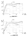
- FIG. 10A illustrates, as a function of the travel of deformation X, the resistance force Fexp (obtained by simulation) that opposes this deformation, during a shock with the leg of a pedestrian at a speed of 40 kilometers per hour, the device illustrated in FIG. 1 and of which the shell and the absorber each have a thickness of 3 millimeters.
- the Fexp force is same order of magnitude as the maximum force desired Fmax, and almost always remains below 6000 newtons.
- Figure 10B is a diagram similar to that of FIG. 10A, plot for the device illustrated in Figure 2 and whose shell and absorber each have a thickness of 3 millimeters.
- the Fexp force is of the same order of magnitude as the maximum desired force Fmax, and remains practically always less than 6000 newtons.
- FIGS. 11A and 11B illustrate a variant of the absorber in which the absorber is mounted by longitudinal sliding on a straight beam in aluminum produced by extrusion.
- the absorber-beam connection is therefore of the type cooperating relief slide 19, 29, and does not require screws or other fasteners.
- This variant has the advantage of offering a very easy mounting of the absorber on the beam, which can be straight or curved with a radius of curvature constant.
Abstract
Description
- la Figure 1 est une vue en coupe transversale d'un dispositif d'absorption d'énergie cinétique conforme à un premier mode de réalisation possible de l'invention;
- la Figure 2 est une vue en coupe transversale d'un dispositif d'absorption d'énergie cinétique conforme à un second mode de réalisation possible de l'invention;
- la Figure 3 est une vue en coupe transversale d'un dispositif d'absorption d'énergie cinétique conforme à une première variante du premier mode de réalisation de l'invention illustré à la figure 1;
- la Figure 4 est une vue partielle en perspective de l'absorbeur et des moyens d'écartement du dispositif illustré à la figure 3;
- la Figure 5 est une vue partielle en perspective d'un dispositif d'absorption d'énergie cinétique conforme à une seconde variante du premier mode de réalisation de l'invention;
- la Figure 6 est une vue en perspective d'un absorbeur utilisable dans un dispositif d'absorption d'énergie cinétique conforme au premier mode de réalisation de l'invention;
- la Figure 7 illustre plusieurs coupes de l'absorbeur de la figure 6, les coupes étant réalisées en différents points de la dimension longitudinale du dispositif;
- la Figure 8 est une vue en perspective d'une coupe médiane d'un absorbeur utilisable dans un dispositif d'absorption d'énergie cinétique conforme au premier mode de réalisation de l'invention, représenté dans un état déformé;
- la Figure 9A est un diagramme schématique illustrant la loi qui relie l'amplitude de la compression subie par la coquille d'un dispositif conforme à l'invention, à la force de compression qui s'exerce sur cette coquille;
- la Figure 9B est un diagramme schématique illustrant la loi qui relie l'amplitude de la compression subie par l'absorbeur d'un dispositif conforme à l'invention, à la force de compression qui s'exerce sur cet absorbeur;
- la Figure 9C est un diagramme schématique illustrant la loi qui relie l'amplitude de la compression subie par un dispositif conforme à l'invention, à la force de compression qui s'exerce sur ce dispositif;
- la Figure 10A est un diagramme illustrant, en fonction de la course de déformation X, la force de résistance F qu'oppose à cette déformation, lors d'un choc avec la jambe d'un piéton à une vitesse de 40 kilomètres par heure, un dispositif conforme à la figure 1 et dont la coquille et l'absorbeur ont chacun une épaisseur de 3 millimètres;
- la Figure 10B est un diagramme illustrant, en fonction de la course de déformation X, la force de résistance F qu'oppose à cette déformation, lors d'un choc avec la jambe d'un piéton à une vitesse de 40 kilomètres par heure, un dispositif conforme à la figure 2 et dont la coquille et l'absorbeur ont chacun une épaisseur de 3 millimètres ;
- la figure 11A est une vue en perspective d'une coupe médiane d'un absorbeur selon une autre variante ; et
- la figure 11B est une vue en coupe partielle agrandie de l'absorbeur illustré à la figure 11A.
Claims (18)
- Dispositif d'absorption d'énergie cinétique formé d'un empilement comprenant une poutre rigide (1) s'étendant suivant une dimension longitudinale (L1), un absorbeur (2) recouvrant la poutre (1), et une coquille externe (3) recouvrant au moins partiellement l'absorbeur (2), l'empilement présentant, dans une section transversale par rapport à la dimension longitudinale (L1), une épaisseur (E) s'étendant suivant un plan longitudinal médian (PL) de la poutre (1) et une largeur (L2) s'étendant transversalement à ce plan longitudinal médian (PL), et ce dispositif subissant, en réponse à un choc d'intensité supérieure à une valeur minimale déterminée, appliqué sur la coquille (3) et dirigé vers la poutre (1), des déformations de la coquille (3) et de l'absorbeur (2) se traduisant notamment par une compression de l'empilement suivant son épaisseur (E), caractérisé en ce que la coquille (3) et l'absorbeur (2) sont réalisés dans des matériaux élastiquement déformables, en ce que chaque élément de l'empilement que constituent séparément la poutre (1), l'absorbeur (2) et la coquille (3) présente un premier voile (11, 21, 31), un second voile (12, 22, 32), et une base (10, 20, 30), en ce que l'absorbeur (2) et la coquille (3) définissent des volumes libres respectifs (200, 300) dans lesquels s'inscrivent respectivement la poutre (1) et l'absorbeur (2), les bases (10, 20, 30) étant empilées suivant l'épaisseur (E) de l'empilement, les premiers voiles (11, 21, 31) étant empilés suivant la largeur (L2) de l'empilement, d'un premier côté (PL1) du plan longitudinal médian (PL), et les seconds voiles (12, 22, 32) étant empilés suivant la largeur (L2) de l'empilement, d'un second côté (PL2) du plan longitudinal médian (PL), en ce que les premier et second voiles (21, 22) de l'absorbeur (2) présentent des premier et second bords respectifs (211, 222) par lesquels ces voiles (21, 22) sont respectivement fixés aux premier et second voiles (11, 12) de la poutre (1), en ce que la base (20) de l'absorbeur (2) est espacée de la base (10) de la poutre (1) suivant l'épaisseur (E) de l'empilement, en ce que les voiles (31, 32) de la coquille (3) sont espacés des voiles (21, 22) de l'absorbeur (2) suivant la largeur (L2) de l'empilement, et en ce que la coquille (3) est fixée à l'empilement de manière à permettre une déformation de sa base (30) dans le plan longitudinal médian (PL).
- Dispositif d'absorption suivant la revendication 1, caractérisé en ce que la coquille (3) est fixée par sa base (30) à la base (20) de l'absorbeur (2).
- Dispositif d'absorption suivant la revendication 1 ou 2, caractérisé en ce que le volume libre (200) défini par l'absorbeur (2) est convexe, les deux voiles (21, 22) de l'absorbeur (2) présentant, en section transversale, des concavités respectives tournées vers ce volume libre (200).
- Dispositif d'absorption suivant l'une quelconque des revendications précédentes, caractérisé en ce qu'il comporte des moyens d'écartement (4) disposés entre le premier voile (21) de l'absorbeur (2) et le premier voile (31) de la coquille (3).
- Dispositif d'absorption suivant la revendication 4, caractérisé en ce que les moyens d'écartement (4) comprennent des entretoises (41) et une traverse (42), les entretoises (41) étant fixées à l'absorbeur (2) et s'étendant vers le premier voile (31) de la coquille (3), et la traverse (42) reliant les entretoises (41) à distance de l'absorbeur (2) et offrant un appui au premier voile (31) de la coquille (3).
- Dispositif d'absorption suivant l'une quelconque des revendications précédentes, caractérisé en ce que les premier et second voiles (11, 12) de la poutre (1) présentent des premier et second rebords respectifs (111, 122), distants de la base (10) de la poutre (1) et s'étendant dans des directions transversales opposées, en ce que les premier et second voiles (21, 22) de l'absorbeur (2) présentent des premier et second rebords respectifs (213, 224), distants de la base (20) de l'absorbeur (2) et s'étendant dans des directions transversales opposées, respectivement en regard des premier et second rebords (111, 122) de la poutre (1), et en ce que l'absorbeur (2) est fixé à la poutre (1) par fixation des rebords (213, 224) de l'absorbeur (2) sur les rebords correspondants (111, 122) de la poutre (1).
- Dispositif d'absorption suivant les revendications 5 et 6, caractérisé en ce que les entretoises (41) prennent appui sur le premier voile (11) de la poutre (1), sont fixées au premier rebord (213) de l'absorbeur (2), et traversent des échancrures (215) pratiquées dans le premier voile (21) de l'absorbeur (2).
- Dispositif d'absorption suivant l'une quelconque des revendications 6 et 7, caractérisé en ce que les premier et second voiles (11, 12) de la poutre (1) divergent l'un de l'autre à partir de la base (10) de cette poutre (1).
- Dispositif d'absorption suivant l'une quelconque des revendications 1 à 5, caractérisé en ce que les premier et second voiles (11, 12) de la poutre (1) sont respectivement recouverts par les premier et second voiles (21, 22) de l'absorbeur (2) en des première et seconde zones de recouvrement (217, 226) respectivement définies en bordure des premier et second voiles (21, 22) de l'absorbeur (2), et en ce que l'absorbeur (2) est fixé à la poutre (1) par fixation des première et seconde zones (217, 226) de recouvrement sur les premier et second voiles (11, 12) de la poutre (1).
- Dispositif d'absorption suivant les revendications 5 et 9, caractérisé en ce que les entretoises (41) sont fixées au premier voile (21) de l'absorbeur (2) dans la première zone (217) de recouvrement.
- Dispositif d'absorption suivant l'une quelconque des revendications 9 et 10, caractérisé en ce que les premier et second voiles (11, 12) de la poutre (1) sont sensiblement parallèles l'un à l'autre.
- Dispositif d'absorption suivant l'une quelconque des revendications précédentes, caractérisé en ce qu'au moins l'absorbeur (2) est réalisé dans un polymère, tel qu'un polypropylène, et formé par injection.
- Dispositif d'absorption suivant l'une quelconque des revendications précédentes, caractérisé en ce que l'absorbeur (2) présente un module d'Young compris entre 750 et 1250 MPa et en ce que les voiles (21, 22) de l'absorbeur (2) ont une épaisseur comprise entre 2 et 5 millimètres.
- Dispositif d'absorption suivant l'une quelconque des revendications précédentes, caractérisé en ce que l'absorbeur (2) présente une épaisseur maximale dans un plan transversal médian (PT) de l'empilement et progressivement décroissante à distance croissante de ce plan (PT).
- Dispositif d'absorption suivant l'une quelconque des revendications 1 à 3, caractérisé en ce que l'absorbeur (2) forme un corps creux, et en ce que les deux voiles (21, 22) de l'absorbeur (2) sont raccordés, à distance de la base (20), par deux parois internes (23, 24) reliées par un fond (25), le volume libre (200) défini par l'absorbeur (2) étant délimité par les parois internes (23, 24) et le fond (25).
- Dispositif d'absorption suivant la revendication 15, caractérisé en ce que l'absorbeur (2) est réalisé dans un polymère, tel qu'un polypropylène, et formé par soufflage.
- Dispositif d'absorption suivant l'une quelconque des revendications précédentes, caractérisé en ce que la coquille (3) est fixée sur la base (20) de l'absorbeur (2) par des moyens de fixation réversible (5), tels que des moyens d'encliquetage.
- Application d'un dispositif d'absorption suivant l'une quelconque des revendications précédentes à la réalisation d'un pare-chocs de véhicule automobile présentant un effort de compression sensiblement constant de l'empilement, dans laquelle la poutre (1) est solidaire du châssis du véhicule et s'étend suivant une direction horizontale.
Applications Claiming Priority (2)
| Application Number | Priority Date | Filing Date | Title |
|---|---|---|---|
| FR0115724A FR2833054B1 (fr) | 2001-12-05 | 2001-12-05 | Dispositif d'absorption d'energie cinetique a resistance elastique et a flambage, et application |
| FR0115724 | 2001-12-05 |
Publications (3)
| Publication Number | Publication Date |
|---|---|
| EP1318323A2 true EP1318323A2 (fr) | 2003-06-11 |
| EP1318323A3 EP1318323A3 (fr) | 2004-12-01 |
| EP1318323B1 EP1318323B1 (fr) | 2008-12-10 |
Family
ID=8870136
Family Applications (1)
| Application Number | Title | Priority Date | Filing Date |
|---|---|---|---|
| EP02292821A Expired - Lifetime EP1318323B1 (fr) | 2001-12-05 | 2002-11-13 | Dispositif d'absorption d'énergie |
Country Status (6)
| Country | Link |
|---|---|
| EP (1) | EP1318323B1 (fr) |
| AT (1) | ATE417214T1 (fr) |
| DE (1) | DE60230230D1 (fr) |
| ES (1) | ES2316535T3 (fr) |
| FR (1) | FR2833054B1 (fr) |
| PT (1) | PT1318323E (fr) |
Cited By (10)
| Publication number | Priority date | Publication date | Assignee | Title |
|---|---|---|---|---|
| FR2888545A1 (fr) * | 2005-07-18 | 2007-01-19 | Peugeot Citroen Automobiles Sa | Ensemble d'absorption d'energie, notamment pour un pare-chocs de vehicule automobile, et vehicule automobile equipe d'un tel ensemble |
| WO2009129881A1 (fr) * | 2008-04-22 | 2009-10-29 | Daimler Ag | Élément déformable pour un véhicule automobile |
| EP2113423A1 (fr) * | 2008-04-30 | 2009-11-04 | Kabushiki Kaisha Kobe Seiko Sho | Système de pare-chocs pour véhicule |
| EP1733926A3 (fr) * | 2005-06-13 | 2009-11-18 | GM Global Technology Operations, Inc. | Structure avant pour véhicule automobile |
| FR2933055A1 (fr) * | 2008-06-30 | 2010-01-01 | Valeo Systemes Thermiques | Systeme d'absorption de choc et face avant comportant un tel systeme d'absorption de choc |
| FR2946302A1 (fr) * | 2009-06-08 | 2010-12-10 | Plastic Omnium Cie | Absorbeur multi-chocs pour vehicule. |
| US7874600B2 (en) | 2008-04-28 | 2011-01-25 | Kobe Steel, Ltd. | Bumper system for vehicle |
| CN101570169B (zh) * | 2008-04-28 | 2013-01-09 | 株式会社神户制钢所 | 车身用保险杠系统 |
| US9580029B2 (en) * | 2015-06-05 | 2017-02-28 | Toyota Motor Engineering & Manufacturing North America, Inc. | Bumper assemblies including a bumper cover reinforcement and vehicles incorporating the same |
| CN108569236A (zh) * | 2017-03-14 | 2018-09-25 | 福特全球技术公司 | 自适应的、吸收能量的保险杠 |
Families Citing this family (1)
| Publication number | Priority date | Publication date | Assignee | Title |
|---|---|---|---|---|
| DE102006011055B4 (de) * | 2006-03-08 | 2011-05-12 | Benteler Automobiltechnik Gmbh | Stoßfängeranordnung |
Citations (6)
| Publication number | Priority date | Publication date | Assignee | Title |
|---|---|---|---|---|
| US3938841A (en) * | 1973-12-07 | 1976-02-17 | Ford Motor Company | Resilient bumper assembly |
| US4652032A (en) * | 1985-10-16 | 1987-03-24 | Borg-Warner Chemicals, Inc. | Vehicle bumper assembly |
| EP0270691A1 (fr) * | 1986-06-27 | 1988-06-15 | Tonen Chemical Corporation | Pare-chocs pour vehicules automobiles |
| US4946727A (en) * | 1989-03-08 | 1990-08-07 | Gerald Kessler | Dual durometer rub rail |
| US4974891A (en) * | 1986-11-14 | 1990-12-04 | Nissan Motor Co., Ltd. | Dynamic damping type bumper for motor vehicle |
| WO2000032444A1 (fr) * | 1998-11-27 | 2000-06-08 | Bayerische Motoren Werke Aktiengesellschaft | Ensemble de montage de pare-chocs d'automobile |
-
2001
- 2001-12-05 FR FR0115724A patent/FR2833054B1/fr not_active Expired - Fee Related
-
2002
- 2002-11-13 ES ES02292821T patent/ES2316535T3/es not_active Expired - Lifetime
- 2002-11-13 DE DE60230230T patent/DE60230230D1/de not_active Expired - Lifetime
- 2002-11-13 EP EP02292821A patent/EP1318323B1/fr not_active Expired - Lifetime
- 2002-11-13 PT PT02292821T patent/PT1318323E/pt unknown
- 2002-11-13 AT AT02292821T patent/ATE417214T1/de not_active IP Right Cessation
Patent Citations (6)
| Publication number | Priority date | Publication date | Assignee | Title |
|---|---|---|---|---|
| US3938841A (en) * | 1973-12-07 | 1976-02-17 | Ford Motor Company | Resilient bumper assembly |
| US4652032A (en) * | 1985-10-16 | 1987-03-24 | Borg-Warner Chemicals, Inc. | Vehicle bumper assembly |
| EP0270691A1 (fr) * | 1986-06-27 | 1988-06-15 | Tonen Chemical Corporation | Pare-chocs pour vehicules automobiles |
| US4974891A (en) * | 1986-11-14 | 1990-12-04 | Nissan Motor Co., Ltd. | Dynamic damping type bumper for motor vehicle |
| US4946727A (en) * | 1989-03-08 | 1990-08-07 | Gerald Kessler | Dual durometer rub rail |
| WO2000032444A1 (fr) * | 1998-11-27 | 2000-06-08 | Bayerische Motoren Werke Aktiengesellschaft | Ensemble de montage de pare-chocs d'automobile |
Cited By (13)
| Publication number | Priority date | Publication date | Assignee | Title |
|---|---|---|---|---|
| EP1733926A3 (fr) * | 2005-06-13 | 2009-11-18 | GM Global Technology Operations, Inc. | Structure avant pour véhicule automobile |
| WO2007010165A2 (fr) * | 2005-07-18 | 2007-01-25 | Peugeot Citroen Automobiles Sa | Ensemble d'absorption d'energie, notamment pour un pare-chocs de vehicule automobile, et vehicule automobile equipe d'un tel ensemble |
| WO2007010165A3 (fr) * | 2005-07-18 | 2007-03-29 | Peugeot Citroen Automobiles Sa | Ensemble d'absorption d'energie, notamment pour un pare-chocs de vehicule automobile, et vehicule automobile equipe d'un tel ensemble |
| FR2888545A1 (fr) * | 2005-07-18 | 2007-01-19 | Peugeot Citroen Automobiles Sa | Ensemble d'absorption d'energie, notamment pour un pare-chocs de vehicule automobile, et vehicule automobile equipe d'un tel ensemble |
| WO2009129881A1 (fr) * | 2008-04-22 | 2009-10-29 | Daimler Ag | Élément déformable pour un véhicule automobile |
| CN101570169B (zh) * | 2008-04-28 | 2013-01-09 | 株式会社神户制钢所 | 车身用保险杠系统 |
| US7874600B2 (en) | 2008-04-28 | 2011-01-25 | Kobe Steel, Ltd. | Bumper system for vehicle |
| EP2113423A1 (fr) * | 2008-04-30 | 2009-11-04 | Kabushiki Kaisha Kobe Seiko Sho | Système de pare-chocs pour véhicule |
| FR2933055A1 (fr) * | 2008-06-30 | 2010-01-01 | Valeo Systemes Thermiques | Systeme d'absorption de choc et face avant comportant un tel systeme d'absorption de choc |
| FR2946302A1 (fr) * | 2009-06-08 | 2010-12-10 | Plastic Omnium Cie | Absorbeur multi-chocs pour vehicule. |
| US9580029B2 (en) * | 2015-06-05 | 2017-02-28 | Toyota Motor Engineering & Manufacturing North America, Inc. | Bumper assemblies including a bumper cover reinforcement and vehicles incorporating the same |
| CN108569236A (zh) * | 2017-03-14 | 2018-09-25 | 福特全球技术公司 | 自适应的、吸收能量的保险杠 |
| CN108569236B (zh) * | 2017-03-14 | 2023-06-27 | 福特全球技术公司 | 自适应的、吸收能量的保险杠 |
Also Published As
| Publication number | Publication date |
|---|---|
| ATE417214T1 (de) | 2008-12-15 |
| DE60230230D1 (de) | 2009-01-22 |
| FR2833054A1 (fr) | 2003-06-06 |
| EP1318323B1 (fr) | 2008-12-10 |
| PT1318323E (pt) | 2009-01-30 |
| EP1318323A3 (fr) | 2004-12-01 |
| ES2316535T3 (es) | 2009-04-16 |
| FR2833054B1 (fr) | 2004-07-02 |
Similar Documents
| Publication | Publication Date | Title |
|---|---|---|
| EP1109702B1 (fr) | Poutre de pare-chocs pour vehicules automobiles | |
| FR2855805A1 (fr) | Element de structure pour vehicule, capable d'un meilleur comportement aux chocs | |
| FR2919551A1 (fr) | Dispositif d'absorption des chocs | |
| EP1318323B1 (fr) | Dispositif d'absorption d'énergie | |
| FR2829083A1 (fr) | Poutre de pare-chocs de vehicule automobile a voile intermediaire | |
| EP1874589B1 (fr) | Ensemble d'une peau de pare-chocs et d'un absorbeur | |
| EP3055170B1 (fr) | Systeme amortisseur de choc pour vehicule automobile | |
| EP1422110B1 (fr) | Pare-chocs de véhicule automobile comportant un bloc compressible à section transversale croissante | |
| WO2006100362A1 (fr) | Piece injectee, ensemble d’absorption d’energie a entretoise, et procede de fabrication d’un tel ensemble | |
| FR2759338A1 (fr) | Dispositif d'absorption d'energie et vehicule, notamment ferroviaire, comportant un tel dispositif d'absorption | |
| EP2096002A1 (fr) | Dispositif d'absorption de choc avec absorbeurs supérieur et inférieur reliés par un élément de liaison déformable | |
| FR2727372A1 (fr) | Dispositif d'absorption d'energie d'une colonne de direction de vehicule automobile | |
| FR3060511A1 (fr) | Structure de soubassement d’un vehicule automobile, notamment hybride, adaptee pour un choc lateral | |
| EP0637538B1 (fr) | Poutre d'absorption d'énergie notamment pour longerons ou traverses de véhicules | |
| WO2008090274A1 (fr) | Dispositif de liaison de deux éléments de structure de véhicule automobile | |
| FR2741413A1 (fr) | Absorbeur de chocs pour vehicule automobile | |
| EP1902907B1 (fr) | Dispositif d'absorption d'énergie pour poutre pare-chocs de véhicule automobile | |
| FR2833055A1 (fr) | Dispositif mecanique a ressorts croises, et application a l'absorption d'energie cinetique | |
| EP2881303A1 (fr) | Dispositif d'amortissement, notamment pour un dispositif d'attelage de véhicule ferroviaire | |
| EP3256348B1 (fr) | Support central de pare-choc arrière | |
| EP1742818A1 (fr) | Boitier de deformation pour vehicule automobile | |
| FR3013667A1 (fr) | Gaine colonne de direction articulee et vehicule equipe d'une telle gaine | |
| FR2728038A1 (fr) | Poutre d'absorption d'energie et flan metallique mince pour realiser cette poutre d'absorption d'energie | |
| FR3047929A1 (fr) | Dispositif coulissant, notamment pour pare-soleil de vehicule, et pare-soleil equipe d'un tel dispositif | |
| WO2009030557A1 (fr) | Absorbeur de choc pour vehicules automobiles et dispositif comportant un tel absorbeur |
Legal Events
| Date | Code | Title | Description |
|---|---|---|---|
| PUAI | Public reference made under article 153(3) epc to a published international application that has entered the european phase |
Free format text: ORIGINAL CODE: 0009012 |
|
| AK | Designated contracting states |
Designated state(s): AT BE BG CH CY CZ DE DK EE ES FI FR GB GR IE IT LI LU MC NL PT SE SK TR |
|
| AX | Request for extension of the european patent |
Extension state: AL LT LV MK RO SI |
|
| PUAL | Search report despatched |
Free format text: ORIGINAL CODE: 0009013 |
|
| AK | Designated contracting states |
Kind code of ref document: A3 Designated state(s): AT BE BG CH CY CZ DE DK EE ES FI FR GB GR IE IT LI LU MC NL PT SE SK TR |
|
| AX | Request for extension of the european patent |
Extension state: AL LT LV MK RO SI |
|
| RIC1 | Information provided on ipc code assigned before grant |
Ipc: 7B 60R 19/18 B Ipc: 7F 16F 7/12 A |
|
| 17P | Request for examination filed |
Effective date: 20050503 |
|
| AKX | Designation fees paid |
Designated state(s): AT BE BG CH CY CZ DE DK EE ES FI FR GB GR IE IT LI LU MC NL PT SE SK TR |
|
| GRAP | Despatch of communication of intention to grant a patent |
Free format text: ORIGINAL CODE: EPIDOSNIGR1 |
|
| GRAS | Grant fee paid |
Free format text: ORIGINAL CODE: EPIDOSNIGR3 |
|
| GRAA | (expected) grant |
Free format text: ORIGINAL CODE: 0009210 |
|
| AK | Designated contracting states |
Kind code of ref document: B1 Designated state(s): AT BE BG CH CY CZ DE DK EE ES FI FR GB GR IE IT LI LU MC NL PT SE SK TR |
|
| REG | Reference to a national code |
Ref country code: GB Ref legal event code: FG4D Free format text: NOT ENGLISH |
|
| REG | Reference to a national code |
Ref country code: CH Ref legal event code: EP |
|
| REG | Reference to a national code |
Ref country code: GB Ref legal event code: 746 Effective date: 20081222 |
|
| REG | Reference to a national code |
Ref country code: IE Ref legal event code: FG4D Free format text: LANGUAGE OF EP DOCUMENT: FRENCH |
|
| REF | Corresponds to: |
Ref document number: 60230230 Country of ref document: DE Date of ref document: 20090122 Kind code of ref document: P |
|
| REG | Reference to a national code |
Ref country code: PT Ref legal event code: SC4A Free format text: AVAILABILITY OF NATIONAL TRANSLATION Effective date: 20090119 |
|
| REG | Reference to a national code |
Ref country code: ES Ref legal event code: FG2A Ref document number: 2316535 Country of ref document: ES Kind code of ref document: T3 |
|
| PG25 | Lapsed in a contracting state [announced via postgrant information from national office to epo] |
Ref country code: NL Free format text: LAPSE BECAUSE OF FAILURE TO SUBMIT A TRANSLATION OF THE DESCRIPTION OR TO PAY THE FEE WITHIN THE PRESCRIBED TIME-LIMIT Effective date: 20081210 Ref country code: FI Free format text: LAPSE BECAUSE OF FAILURE TO SUBMIT A TRANSLATION OF THE DESCRIPTION OR TO PAY THE FEE WITHIN THE PRESCRIBED TIME-LIMIT Effective date: 20081210 |
|
| NLV1 | Nl: lapsed or annulled due to failure to fulfill the requirements of art. 29p and 29m of the patents act | ||
| REG | Reference to a national code |
Ref country code: IE Ref legal event code: FD4D |
|
| PG25 | Lapsed in a contracting state [announced via postgrant information from national office to epo] |
Ref country code: BG Free format text: LAPSE BECAUSE OF FAILURE TO SUBMIT A TRANSLATION OF THE DESCRIPTION OR TO PAY THE FEE WITHIN THE PRESCRIBED TIME-LIMIT Effective date: 20090310 Ref country code: IE Free format text: LAPSE BECAUSE OF FAILURE TO SUBMIT A TRANSLATION OF THE DESCRIPTION OR TO PAY THE FEE WITHIN THE PRESCRIBED TIME-LIMIT Effective date: 20081210 Ref country code: EE Free format text: LAPSE BECAUSE OF FAILURE TO SUBMIT A TRANSLATION OF THE DESCRIPTION OR TO PAY THE FEE WITHIN THE PRESCRIBED TIME-LIMIT Effective date: 20081210 |
|
| PG25 | Lapsed in a contracting state [announced via postgrant information from national office to epo] |
Ref country code: CZ Free format text: LAPSE BECAUSE OF FAILURE TO SUBMIT A TRANSLATION OF THE DESCRIPTION OR TO PAY THE FEE WITHIN THE PRESCRIBED TIME-LIMIT Effective date: 20081210 Ref country code: AT Free format text: LAPSE BECAUSE OF FAILURE TO SUBMIT A TRANSLATION OF THE DESCRIPTION OR TO PAY THE FEE WITHIN THE PRESCRIBED TIME-LIMIT Effective date: 20081210 Ref country code: SE Free format text: LAPSE BECAUSE OF FAILURE TO SUBMIT A TRANSLATION OF THE DESCRIPTION OR TO PAY THE FEE WITHIN THE PRESCRIBED TIME-LIMIT Effective date: 20090310 |
|
| PLBE | No opposition filed within time limit |
Free format text: ORIGINAL CODE: 0009261 |
|
| STAA | Information on the status of an ep patent application or granted ep patent |
Free format text: STATUS: NO OPPOSITION FILED WITHIN TIME LIMIT |
|
| PG25 | Lapsed in a contracting state [announced via postgrant information from national office to epo] |
Ref country code: DK Free format text: LAPSE BECAUSE OF FAILURE TO SUBMIT A TRANSLATION OF THE DESCRIPTION OR TO PAY THE FEE WITHIN THE PRESCRIBED TIME-LIMIT Effective date: 20081210 |
|
| 26N | No opposition filed |
Effective date: 20090911 |
|
| BERE | Be: lapsed |
Owner name: PEUGEOT CITROEN AUTOMOBILES SA Effective date: 20091130 |
|
| PG25 | Lapsed in a contracting state [announced via postgrant information from national office to epo] |
Ref country code: MC Free format text: LAPSE BECAUSE OF NON-PAYMENT OF DUE FEES Effective date: 20091130 |
|
| REG | Reference to a national code |
Ref country code: CH Ref legal event code: PL |
|
| GBPC | Gb: european patent ceased through non-payment of renewal fee |
Effective date: 20091113 |
|
| PG25 | Lapsed in a contracting state [announced via postgrant information from national office to epo] |
Ref country code: LI Free format text: LAPSE BECAUSE OF NON-PAYMENT OF DUE FEES Effective date: 20091130 Ref country code: BE Free format text: LAPSE BECAUSE OF NON-PAYMENT OF DUE FEES Effective date: 20091130 Ref country code: GR Free format text: LAPSE BECAUSE OF FAILURE TO SUBMIT A TRANSLATION OF THE DESCRIPTION OR TO PAY THE FEE WITHIN THE PRESCRIBED TIME-LIMIT Effective date: 20090311 Ref country code: CH Free format text: LAPSE BECAUSE OF NON-PAYMENT OF DUE FEES Effective date: 20091130 |
|
| PG25 | Lapsed in a contracting state [announced via postgrant information from national office to epo] |
Ref country code: GB Free format text: LAPSE BECAUSE OF NON-PAYMENT OF DUE FEES Effective date: 20091113 |
|
| REG | Reference to a national code |
Ref country code: ES Ref legal event code: GC2A Effective date: 20110207 |
|
| PG25 | Lapsed in a contracting state [announced via postgrant information from national office to epo] |
Ref country code: IT Free format text: LAPSE BECAUSE OF NON-PAYMENT OF DUE FEES Effective date: 20091113 |
|
| PG25 | Lapsed in a contracting state [announced via postgrant information from national office to epo] |
Ref country code: LU Free format text: LAPSE BECAUSE OF NON-PAYMENT OF DUE FEES Effective date: 20091113 |
|
| PG25 | Lapsed in a contracting state [announced via postgrant information from national office to epo] |
Ref country code: TR Free format text: LAPSE BECAUSE OF FAILURE TO SUBMIT A TRANSLATION OF THE DESCRIPTION OR TO PAY THE FEE WITHIN THE PRESCRIBED TIME-LIMIT Effective date: 20081210 |
|
| PG25 | Lapsed in a contracting state [announced via postgrant information from national office to epo] |
Ref country code: CY Free format text: LAPSE BECAUSE OF FAILURE TO SUBMIT A TRANSLATION OF THE DESCRIPTION OR TO PAY THE FEE WITHIN THE PRESCRIBED TIME-LIMIT Effective date: 20081210 |
|
| REG | Reference to a national code |
Ref country code: FR Ref legal event code: PLFP Year of fee payment: 14 |
|
| REG | Reference to a national code |
Ref country code: FR Ref legal event code: PLFP Year of fee payment: 15 |
|
| PGFP | Annual fee paid to national office [announced via postgrant information from national office to epo] |
Ref country code: SK Payment date: 20161026 Year of fee payment: 15 Ref country code: DE Payment date: 20161020 Year of fee payment: 15 |
|
| PGFP | Annual fee paid to national office [announced via postgrant information from national office to epo] |
Ref country code: ES Payment date: 20161024 Year of fee payment: 15 Ref country code: PT Payment date: 20161102 Year of fee payment: 15 |
|
| REG | Reference to a national code |
Ref country code: FR Ref legal event code: PLFP Year of fee payment: 16 |
|
| REG | Reference to a national code |
Ref country code: DE Ref legal event code: R119 Ref document number: 60230230 Country of ref document: DE |
|
| REG | Reference to a national code |
Ref country code: FR Ref legal event code: CA Effective date: 20180312 Ref country code: FR Ref legal event code: CD Owner name: PEUGEOT CITROEN AUTOMOBILES SA, FR Effective date: 20180312 |
|
| PG25 | Lapsed in a contracting state [announced via postgrant information from national office to epo] |
Ref country code: SK Free format text: LAPSE BECAUSE OF NON-PAYMENT OF DUE FEES Effective date: 20171113 Ref country code: PT Free format text: LAPSE BECAUSE OF NON-PAYMENT OF DUE FEES Effective date: 20180514 |
|
| REG | Reference to a national code |
Ref country code: SK Ref legal event code: MM4A Ref document number: E 4946 Country of ref document: SK Effective date: 20171113 |
|
| REG | Reference to a national code |
Ref country code: FR Ref legal event code: PLFP Year of fee payment: 17 |
|
| PG25 | Lapsed in a contracting state [announced via postgrant information from national office to epo] |
Ref country code: DE Free format text: LAPSE BECAUSE OF NON-PAYMENT OF DUE FEES Effective date: 20180602 |
|
| REG | Reference to a national code |
Ref country code: ES Ref legal event code: FD2A Effective date: 20181226 |
|
| PG25 | Lapsed in a contracting state [announced via postgrant information from national office to epo] |
Ref country code: ES Free format text: LAPSE BECAUSE OF NON-PAYMENT OF DUE FEES Effective date: 20171114 |
|
| PGFP | Annual fee paid to national office [announced via postgrant information from national office to epo] |
Ref country code: FR Payment date: 20191022 Year of fee payment: 18 |
|
| PG25 | Lapsed in a contracting state [announced via postgrant information from national office to epo] |
Ref country code: FR Free format text: LAPSE BECAUSE OF NON-PAYMENT OF DUE FEES Effective date: 20201130 |