EP1318275B1 - Structure for separating the high and low pressure turboexpanders of a gas turbine - Google Patents
Structure for separating the high and low pressure turboexpanders of a gas turbine Download PDFInfo
- Publication number
- EP1318275B1 EP1318275B1 EP02258433A EP02258433A EP1318275B1 EP 1318275 B1 EP1318275 B1 EP 1318275B1 EP 02258433 A EP02258433 A EP 02258433A EP 02258433 A EP02258433 A EP 02258433A EP 1318275 B1 EP1318275 B1 EP 1318275B1
- Authority
- EP
- European Patent Office
- Prior art keywords
- low pressure
- diaphragm
- high pressure
- outlet ducts
- structure according
- Prior art date
- Legal status (The legal status is an assumption and is not a legal conclusion. Google has not performed a legal analysis and makes no representation as to the accuracy of the status listed.)
- Expired - Lifetime
Links
- 238000001816 cooling Methods 0.000 claims description 26
- 238000007789 sealing Methods 0.000 claims description 19
- 238000002347 injection Methods 0.000 claims description 3
- 239000007924 injection Substances 0.000 claims description 3
- 239000007789 gas Substances 0.000 description 31
- 238000002485 combustion reaction Methods 0.000 description 6
- 238000010438 heat treatment Methods 0.000 description 3
- 239000000446 fuel Substances 0.000 description 2
- 230000008646 thermal stress Effects 0.000 description 2
- 230000007704 transition Effects 0.000 description 2
- 238000006243 chemical reaction Methods 0.000 description 1
- 230000006866 deterioration Effects 0.000 description 1
- 239000012530 fluid Substances 0.000 description 1
- 238000002955 isolation Methods 0.000 description 1
- 239000007788 liquid Substances 0.000 description 1
- 238000012423 maintenance Methods 0.000 description 1
- 238000004519 manufacturing process Methods 0.000 description 1
- 239000000463 material Substances 0.000 description 1
- 239000000203 mixture Substances 0.000 description 1
- 230000002093 peripheral effect Effects 0.000 description 1
- 238000000926 separation method Methods 0.000 description 1
Images


Classifications
-
- F—MECHANICAL ENGINEERING; LIGHTING; HEATING; WEAPONS; BLASTING
- F01—MACHINES OR ENGINES IN GENERAL; ENGINE PLANTS IN GENERAL; STEAM ENGINES
- F01D—NON-POSITIVE DISPLACEMENT MACHINES OR ENGINES, e.g. STEAM TURBINES
- F01D25/00—Component parts, details, or accessories, not provided for in, or of interest apart from, other groups
- F01D25/24—Casings; Casing parts, e.g. diaphragms, casing fastenings
-
- F—MECHANICAL ENGINEERING; LIGHTING; HEATING; WEAPONS; BLASTING
- F02—COMBUSTION ENGINES; HOT-GAS OR COMBUSTION-PRODUCT ENGINE PLANTS
- F02C—GAS-TURBINE PLANTS; AIR INTAKES FOR JET-PROPULSION PLANTS; CONTROLLING FUEL SUPPLY IN AIR-BREATHING JET-PROPULSION PLANTS
- F02C7/00—Features, components parts, details or accessories, not provided for in, or of interest apart form groups F02C1/00 - F02C6/00; Air intakes for jet-propulsion plants
- F02C7/28—Arrangement of seals
-
- F—MECHANICAL ENGINEERING; LIGHTING; HEATING; WEAPONS; BLASTING
- F01—MACHINES OR ENGINES IN GENERAL; ENGINE PLANTS IN GENERAL; STEAM ENGINES
- F01D—NON-POSITIVE DISPLACEMENT MACHINES OR ENGINES, e.g. STEAM TURBINES
- F01D11/00—Preventing or minimising internal leakage of working-fluid, e.g. between stages
Definitions
- the present invention relates to a structure for separating the high and low pressure turboexpanders of a gas turbine.
- the invention relates to a structure for separating the high and low pressure turboexpanders of a multi-stage axial gas turbine.
- gas turbine denotes the whole of a rotary heat engine which converts the enthalpy of a gas to useful work, using gases obtained directly from a combustion process and supplying mechanical power on an output shaft.
- the turbine therefore usually comprises one or more compressors or turbocompressors, in which air drawn from the outside is pressurized.
- Various injectors supply the fuel, which is mixed with the air to form a fuel-air mixture for ignition.
- the axial compressor is driven by a turbine, properly so called, or turboexpander, which supplies mechanical energy to a user by converting the enthalpy of the gases burnt in the combustion chamber.
- the turboexpander, the turbocompressor, the combustion chamber (or heater), the output shaft for the mechanical energy, the control system and the starting system form the essential components of a gas turbine machine.
- the gas is characterized by low pressure and low temperature, but as it passes through the compressor the gas is compressed and its temperature rises.
- the heat required to raise the gas temperature is supplied by the burning of liquid fuel introduced by injectors into the heating chamber.
- Ignition is carried out by sparking plugs when the machine is started.
- the gas At the outlet of the combustion chamber, the gas, at high pressure and high temperature, passes through suitable ducts, reaches the turbine, where it gives up some of the energy accumulated in the compressor and in the heating (combustion) chamber, and then flows to the outside through the exhaust ducts.
- Turbines designed for high power production are generally made with multiple stages to optimize the efficiency of conversion of the energy yielded by the gas into useful work.
- Each stage of the turbocompressor and of the turboexpander is designed to operate in certain conditions of pressure, temperature and velocity of the gas.
- thermodynamics From the science of thermodynamics it is also known that, in order to obtain the maximum efficiency from any given gas turbine, the gas temperature must be as high as possible, subject to compatibility with the materials that can be used for the components.
- the operating conditions can therefore be particularly severe and can cause rapid deterioration of the turbine components in some areas.
- cooling systems are provided in critical areas, in order to prevent dangerous rises in temperature.
- air can be drawn off from an appropriate stage of the compressor and blown through a system of ducts into the critical area of the stage of the turboexpander for this purpose.
- an effective isolation system must be provided to separate the high pressure stages from the low pressure stages.
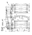
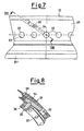
- a gas turbine according to the prior art has a high pressure turboexpander AP and a low pressure turboexpander BP, illustrated schematically in Figure 1 attached to the present description.
- turboexpanders which operate at different pressures, are separated by a pair of convex plates 2 and 3 made in the form of a circular ring which has a convex surface and is fixed along its outer and inner circumferences.
- the separating system according to the prior art which has been described has areas for the outlet of the cooling air only in the proximity of the high pressure rotor disc 6 and not in other critical areas of the stage.
- the two convex plates 2 and 3 have a drawback in respect of their overall dimensions, which prevent the positioning of the high and low pressure rotors close to each other because they require the use of a transition element 7 between the two turboexpanders, resulting in a pressure drop and consequently a decrease in the efficiency of the turbine.
- the object of the present invention is to provide a structure for separating the high and low pressure turboexpanders of a gas turbine, which is free of the drawbacks mentioned above.
- Another object of the present invention is to propose a separating structure which enables cooling air to be directed towards hot areas within the gas turbine, such as the high and low pressure wheel housings and the high pressure rotor disc rod.
- US 6,179,555 discloses a sealing device and plenum assembly particularly adapted for forming a plenum inwardly of a circumferential stator blade array in a gas turbine engine.
- US 4,117,669 discloses a gas turbine wherein the thermal stresses in the turbine rotor are reduced.
- the rotor includes a central disc with a peripheral rim, and a plurality of blades extending radially outwardly from the rim, and to reduce thermal stresses, a duct arrangement is provided which selectively directs hot gases from the turbine combustor to the rim during the turbine start-up.
- the present invention seeks to provide a support for the sealing ring which isolates the high and low pressure environments.
- a structure for separating high and low pressure turboexpanders of a gas turbine comprising a diaphragm, positioned coaxially behind a stator channel between a stage of a high pressure turboexpander and a first stage of a low pressure turboexpander and a pair of shaped plates fixed to the diaphragm and forming a gap into which the cooling air is blown, and a sealing ring designed to isolate the high pressure turboexpanders from the low pressure turboexpanders wherein the sealing ring is supported by the shaped plates and the diaphragm additionally comprises a plurality of high pressure outlet ducts and a plurality of low pressure outlet ducts for respectively directing cooling air towards the high pressure turboexpander and the low pressure turboexpander whereby the diaphragm and sealing ring together having the function of sending flows of cooling air towards hot areas of the high and low pressure turboexpanders and receiving and distributing the cooling air obtained from the gap.
- the said diaphragm may comprise an annular body having a plurality of radial through holes for the injection of the cooling air.
- Each of the radial holes may be used to fix the diaphragm to a stator array of nozzles by means of bushes, each of which is held in place by a fixing ring.
- the diaphragm may additionally comprise a plurality of high pressure outlet ducts directed towards connections connecting high pressure rotor blades to a disc of the said stage f the high pressure turboexpander.
- the said diaphragm may additionally comprises a plurality of low pressure outlet ducts directed towards connections connecting low pressure rotor blades to a disc of the said first stage of the low pressure turboexpander.
- Each of the said high and low pressure outlet ducts may start from a different radial hole in the diaphragm.
- the number of the said high pressure outlet ducts provided may be twice the number of the low pressure outlet ducts and the ducts may be positioned in a regularly alternating pattern with every two high pressure outlet ducts followed by one low pressure outlet duct.
- the diaphragm may have a maximum external diameter (D) of 477.8 mm, and may have 48 radial holes.
- the diaphragm may also have at least one connecting channel with the gap for the distribution of the cooling air.
- Six connecting channels may be formed which start from the same number of low pressure outlet ducts.
- the shaped plates may be made in the form of a circular ring having a circumferential convexity facing the high pressure turboexpande, in such a way that they follow the profiles of the rotor discs of the high and low pressure stages respectively, between which the said shaped plates are fitted.
- the said convexity may have a radius of curvature of 23 mm, and may be formed in shaped plates having an external diameter of 417 mm, fixed to a diaphragm having a maximum diameter of 477.8 mm.
- the diaphragm may incorporate in its lower part an inner ring extending radially towards the longitudinal axis of the diaphragm, the said inner ring being provided with a plurality of plate fixing holes through which the said shaped plates are bolted to the diaphragm in the proximity of their outer circumference.
- the sealing ring may have a circumferential edge extending radially outwards from its upper surface, this edge being provided with a plurality of longitudinal holes positioned parallel to the longitudinal axis of the diaphragm for fixing to the said shaped plates.
- the circumferential edge of the said sealing ring is pierced radially by a plurality of air ducts, designed to receive the air from the gap and to send it to the proximity of a central rod which maintains the contact between the said disc of the said stage of the high pressure turboexpander and a rotor of the turbocompressor.
- the structure for separating the high and low pressure turboexpanders comprises a diaphragm for receiving cooling air drawn from a stage of a turbocompressor, a pair of shaped plates bolted at one end to the diaphragm, and a sealing ring bolted to the other ends of the shaped plates and supported by them.
- the structure provides a separation between the high and low pressure stages and, because of the gap formed by the space between the shaped plates, allows the cooling air to be conveyed through the diaphragm towards hot areas of the turboexpanders.
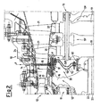
- a turbine 10 comprises a turbocompressor 11, a high pressure turboexpander 12 comprising a stage 12', and a low pressure turboexpander 13 comprising two stages, numbered 13' and 13", where the term "stage” denotes a rotor and stator assembly.
- turbocompressor 11 and the high pressure turboexpander 12 are mounted on a first shaft, while the two stages 13', 13" of the low pressure turboexpander 13 are mounted on a second shaft separated from the first (the shafts are not shown).
- Both shafts are rotatable at different velocities about an axis 23 inside a casing 24 which forms the fixed part, or stator, of the turbine 10.
- This configuration makes it possible to optimize efficiency since, in multi-stage turbines, the gas is processed in the high pressure turboexpander at a fairly high temperature and pressure, and undergoes a first expansion therein.
- the energy obtained from the expansion of the gas in the high pressure stage 12' is used to move the turbocompressor 11, while the low pressure stages 13' and 13" are those which, in practice, supply the useful work.
- the stage 12' of the high pressure turboexpander 12 comprises a disc 16 carrying a plurality of high pressure rotor blades 18 fixed by connections 17.
- a central rod 22 located in the proximity of the axis of rotation 23 is used to keep the disc 16 in contact with the rotor of the turbocompressor 11.
- Each of the stages 13' and 13" of the low pressure turboexpander 13 comprises a disc 19 carrying a plurality of low pressure rotor blades 21, fixed by connections 20.
- the rotor blading of the stage 12' of the high pressure turboexpander 12 and of the first stage 13' of the low pressure turboexpander 13 form rotating ducts separated by a fixed duct or stator channel 14.
- the high and low pressure turboexpanders 12 and 13 are separated from each other by a separating structure 30 which comprises a diaphragm 31, positioned coaxially behind the stator channel 14 and radially below the said stator channel.
- the diaphragm 31 has the function of sending cooling air flows drawn from a suitably chosen stage of the turbocompressor 11 towards hot areas of the high and low pressure turboexpanders 12 and 13, in the directions shown by the arrows F in Figure 2 .
- the separating structure 30 also comprises a pair of shaped plates 50' and 50", fixed to the diaphragm 31 and forming a gap 52 into which the cooling air is blown; and a sealing ring 60 supported by the shaped plates 50' and 50" and designed to isolate the operating environments of the high pressure turboexpanders 12 and the low pressure turboexpanders 13, to receive the cooling air from the gap 52 and to distribute it towards an area at critical temperature, consisting of the space between the rod 22 and the high pressure rotor disc 16.
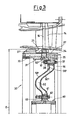
- the diaphragm 31 comprises an annular body 31' having, on its surface facing the stator channel 14, a plurality of radial holes 32 for the injection of the cooling air.
- Each of the said radial holes 32, made to pass through the body 31', is made in order to fix the said diaphragm to a stator array of nozzles 15 which are closed by bushes 38 held in place by a fixing ring 38'.
- the aforesaid bushes 38 receive the cooling ducts which pass through the nozzles and, by means of holes in the bushes, make these ducts communicate with the high and low pressure outlet ducts 33 and 34.
- the body 31' of the diaphragm 31 comprises a circumferential stop 31" designed to bear against a corresponding projecting portion 25 formed in the nozzles 15 for the correct positioning of the separating structure 30.
- the diaphragm 31 thus comprises a plurality of high pressure outlet ducts 33 directed towards the connections 17 connecting the high pressure rotor blades 18 to the disc 16, and a plurality of low pressure outlet ducts 34 directed towards the connections 20 connecting the low pressure rotor blades 21 to the disc 19.
- Each of these high and low pressure outlet ducts 33 and 34 starts from a different radial hole 32 in the diaphragm 31 in directions which carry the flows of cooling air emitted by them towards the chosen critical areas.
- the high pressure outlet ducts 33 are made in a horizontal configuration while the low pressure outlet ducts 34 are made in an inclined configuration.
- the high pressure outlet ducts 33 and the low pressure outlet ducts 34 are also oblique with respect to the longitudinal axis of the diaphragm 31 which coincides with the axis of rotation 23 of the rotors, in order to direct the flows of cooling air towards the critical areas which can be reached.
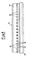
- the number of high pressure outlet ducts 33 provided is twice the number of low pressure outlet ducts 34, and the ducts are positioned in a regularly alternating pattern, in which two high pressure outlet ducts 33 are followed by one low pressure duct 34.
- a diaphragm 31 with a maximum diameter D, measured at the circumferential stop 31", of 477.88 mm, is provided with 48 radial holes 32 and accordingly with 32 high pressure outlet ducts 33 and 16 low pressure outlet ducts 34.
- the diaphragm 31 has at least one connecting channel 35 connected to a low pressure outlet duct 34, in order to direct the flows of cooling air towards the gap 52.
- connecting channels 35 passing radially through an inner ring 36 incorporated in the body 31' of the diaphragm 31 and extending towards the central axis 23.
- the connecting channels 35 are positioned at unequal intervals along the circumference of the ring 36.
- each of the shaped plates 50' and 50" is made in the form of a circular ring having a convexity 51 of identical curvature.
- the shaped plates 50' and 50" are positioned radially with the convexity 51 facing the high pressure turboexpander 12, in such a way that they follow the profiles of the rotor discs 16 and 19 of the high and low pressure stages 12' and 13' respectively, between which the separating structure 30 is fitted.
- the plate 50' faces towards the high pressure turboexpander 12, while the shaped plate 50" faces towards the low pressure turboexpander 13.
- the convexity 51 has a radius of curvature R of 23 mm, and is formed in shaped plates 50' and 50" having an external diameter D' of 417 mm, fixed to a diaphragm 31 having a maximum diameter D of 477.8 mm.
- the inner ring 36 of the diaphragm 31 is provided with a plurality of fixing holes 37 positioned parallel to the longitudinal axis of the diaphragm 31, through which the said shaped plates 50', 50" are bolted to the diaphragm 31.
- the shaped plates 50' and 50" are provided with holes 37' formed in the proximity of their outer circumference in such a way as to correspond to the said holes 37.
- the sealing ring 60 has a circumferential edge 61, extending radially outwards from the upper surface of the sealing ring 60, this edge being pierced by a plurality of fixing holes 62, preferably six in number, whose axes are parallel to the longitudinal axis of the sealing ring 60.
- the shaped plates 50' and 50" are provided with holes 62' positioned in the proximity of the inner circumference of the plates and suitably spaced to correspond to the fixing holes 62 made in the sealing ring 60.
- the circumferential edge 61 is also pierced radially by a plurality of air ducts 63, preferably twelve in number, designed to receive the air from the gap 52 and to send it to the proximity of the annular rod 22.
- the circumferential edge 61 also has holes 63' made in it, these holes being designed to increase, where necessary, the number of ducts available for the passage of the air.
- the draw-off stage of the turbocompressor is the seventh stage of an 11-stage turbocompressor.
- the profile chosen for the shaped plates 50' and 50" enables the characteristics of rigidity of the separating structure 30 to be increased in such a way as to limit vibrational phenomena and ensure the correct positioning of the sealing ring.
- the configuration of the shaped plates 50' and 50" enables the two rotors (which rotate at different speeds and operate in different pressure and temperature conditions) to be mounted close together, and therefore enables the transition element 7 to be dispensed with, while also helping to minimize the pressure losses.
Landscapes
- Engineering & Computer Science (AREA)
- Mechanical Engineering (AREA)
- General Engineering & Computer Science (AREA)
- Chemical & Material Sciences (AREA)
- Combustion & Propulsion (AREA)
- Structures Of Non-Positive Displacement Pumps (AREA)
- Turbine Rotor Nozzle Sealing (AREA)
- Diaphragms And Bellows (AREA)
- Supercharger (AREA)
- Separation By Low-Temperature Treatments (AREA)
- Transition And Organic Metals Composition Catalysts For Addition Polymerization (AREA)
Applications Claiming Priority (2)
| Application Number | Priority Date | Filing Date | Title |
|---|---|---|---|
| ITMI20012584 | 2001-12-10 | ||
| IT2001MI002584A ITMI20012584A1 (it) | 2001-12-10 | 2001-12-10 | Struttura di separazione dei turboespansori diaalta e bassa pressionedi una turbina a gas |
Publications (3)
| Publication Number | Publication Date |
|---|---|
| EP1318275A2 EP1318275A2 (en) | 2003-06-11 |
| EP1318275A3 EP1318275A3 (en) | 2004-09-08 |
| EP1318275B1 true EP1318275B1 (en) | 2009-10-21 |
Family
ID=11448673
Family Applications (1)
| Application Number | Title | Priority Date | Filing Date |
|---|---|---|---|
| EP02258433A Expired - Lifetime EP1318275B1 (en) | 2001-12-10 | 2002-12-06 | Structure for separating the high and low pressure turboexpanders of a gas turbine |
Country Status (9)
| Country | Link |
|---|---|
| US (1) | US6769870B2 (enExample) |
| EP (1) | EP1318275B1 (enExample) |
| JP (1) | JP4262971B2 (enExample) |
| KR (1) | KR100746105B1 (enExample) |
| CA (1) | CA2413126C (enExample) |
| DE (1) | DE60234077D1 (enExample) |
| IT (1) | ITMI20012584A1 (enExample) |
| RU (1) | RU2299993C2 (enExample) |
| TW (1) | TWI260365B (enExample) |
Families Citing this family (12)
| Publication number | Priority date | Publication date | Assignee | Title |
|---|---|---|---|---|
| ITMI20041778A1 (it) * | 2004-09-17 | 2004-12-17 | Nuovo Pignone Spa | Fondo bombato di tenuta per una turbina bialbero |
| US7722314B2 (en) * | 2006-06-22 | 2010-05-25 | General Electric Company | Methods and systems for assembling a turbine |
| US7914253B2 (en) * | 2007-05-01 | 2011-03-29 | General Electric Company | System for regulating a cooling fluid within a turbomachine |
| JP4884410B2 (ja) * | 2008-03-04 | 2012-02-29 | 株式会社日立製作所 | 二軸ガスタービン |
| EP2530249A1 (en) | 2011-05-30 | 2012-12-05 | Siemens Aktiengesellschaft | Piston seal ring |
| US9206705B2 (en) * | 2012-03-07 | 2015-12-08 | Mitsubishi Hitachi Power Systems, Ltd. | Sealing device and gas turbine having the same |
| US9291071B2 (en) | 2012-12-03 | 2016-03-22 | United Technologies Corporation | Turbine nozzle baffle |
| US9316153B2 (en) * | 2013-01-22 | 2016-04-19 | Siemens Energy, Inc. | Purge and cooling air for an exhaust section of a gas turbine assembly |
| JP6071629B2 (ja) * | 2013-02-22 | 2017-02-01 | 三菱重工航空エンジン株式会社 | タービン及びガスタービンエンジン |
| JP6961482B2 (ja) * | 2017-12-27 | 2021-11-05 | 三菱重工コンプレッサ株式会社 | 遠心圧縮機および遠心圧縮機の製造方法 |
| RU2691203C1 (ru) * | 2018-07-05 | 2019-06-11 | Публичное акционерное общество "ОДК-Уфимское моторостроительное производственное объединение" (ПАО "ОДК-УМПО") | Сопловый аппарат турбины низкого давления (ТНД) газотурбинного двигателя (ГТД) (варианты) и лопатка соплового аппарата ТНД (варианты) |
| CN110529194B (zh) * | 2019-08-13 | 2020-09-11 | 北京航空航天大学 | 一种减小旋转螺栓风阻的导向器结构 |
Family Cites Families (10)
| Publication number | Priority date | Publication date | Assignee | Title |
|---|---|---|---|---|
| FR965697A (enExample) * | 1950-09-19 | |||
| GB623615A (en) * | 1947-05-06 | 1949-05-19 | Frederick William Walton Morle | Improvements in or relating to gas-turbine-engines |
| GB742288A (en) * | 1951-02-15 | 1955-12-21 | Power Jets Res & Dev Ltd | Improvements in the cooling of turbines |
| US4117669A (en) * | 1977-03-04 | 1978-10-03 | The United States Of America As Represented By The Administrator Of The National Aeronautics And Space Administration | Apparatus and method for reducing thermal stress in a turbine rotor |
| US4173120A (en) * | 1977-09-09 | 1979-11-06 | International Harvester Company | Turbine nozzle and rotor cooling systems |
| US4292008A (en) * | 1977-09-09 | 1981-09-29 | International Harvester Company | Gas turbine cooling systems |
| US4213738A (en) * | 1978-02-21 | 1980-07-22 | General Motors Corporation | Cooling air control valve |
| CA2263508C (en) * | 1997-06-19 | 2003-08-19 | Mitsubishi Heavy Industries, Ltd. | Sealing device for gas turbine stator blades |
| US6179555B1 (en) * | 1998-10-06 | 2001-01-30 | Pratt & Whitney Canada Corp. | Sealing of T.O.B.I feed plenum |
| US6464453B2 (en) * | 2000-12-04 | 2002-10-15 | General Electric Company | Turbine interstage sealing ring |
-
2001
- 2001-12-10 IT IT2001MI002584A patent/ITMI20012584A1/it unknown
-
2002
- 2002-11-28 CA CA2413126A patent/CA2413126C/en not_active Expired - Fee Related
- 2002-12-05 TW TW091135284A patent/TWI260365B/zh not_active IP Right Cessation
- 2002-12-06 DE DE60234077T patent/DE60234077D1/de not_active Expired - Lifetime
- 2002-12-06 EP EP02258433A patent/EP1318275B1/en not_active Expired - Lifetime
- 2002-12-09 RU RU2002133053/06A patent/RU2299993C2/ru active
- 2002-12-09 JP JP2002356103A patent/JP4262971B2/ja not_active Expired - Fee Related
- 2002-12-09 KR KR1020020077792A patent/KR100746105B1/ko not_active Expired - Fee Related
- 2002-12-10 US US10/315,249 patent/US6769870B2/en not_active Expired - Fee Related
Also Published As
| Publication number | Publication date |
|---|---|
| JP2003227311A (ja) | 2003-08-15 |
| ITMI20012584A1 (it) | 2003-06-10 |
| US6769870B2 (en) | 2004-08-03 |
| KR100746105B1 (ko) | 2007-08-03 |
| CA2413126A1 (en) | 2003-06-10 |
| JP4262971B2 (ja) | 2009-05-13 |
| CA2413126C (en) | 2011-03-22 |
| US20030113207A1 (en) | 2003-06-19 |
| RU2299993C2 (ru) | 2007-05-27 |
| EP1318275A2 (en) | 2003-06-11 |
| EP1318275A3 (en) | 2004-09-08 |
| DE60234077D1 (de) | 2009-12-03 |
| TWI260365B (en) | 2006-08-21 |
| TW200409861A (en) | 2004-06-16 |
| KR20030047827A (ko) | 2003-06-18 |
Similar Documents
| Publication | Publication Date | Title |
|---|---|---|
| US4719747A (en) | Apparatus for optimizing the blade and sealing slots of a compressor of a gas turbine | |
| US5503528A (en) | Rim seal for turbine wheel | |
| EP2325438B1 (en) | Seal plates for directing airflow through a turbine section of an engine and turbine sections | |
| EP1555393B1 (en) | Gas turbine engine component having bypass circuit | |
| EP1318275B1 (en) | Structure for separating the high and low pressure turboexpanders of a gas turbine | |
| US6089821A (en) | Gas turbine engine cooling apparatus | |
| EP2261461B1 (en) | Gas turbine and corresponding manufacturing method | |
| US5842831A (en) | Arrangement for the thermal protection of a rotor of a high-pressure compressor | |
| US20020018710A1 (en) | Coolant recovery type gas turbine | |
| CA2927183A1 (en) | Turbine engine advanced cooling system | |
| US20190003326A1 (en) | Compliant rotatable inter-stage turbine seal | |
| US4696619A (en) | Housing for a turbojet engine compressor | |
| US9291071B2 (en) | Turbine nozzle baffle | |
| GB2057573A (en) | Turbine rotor assembly | |
| US20190003381A1 (en) | Method of assembling and disassembling gas turbine and gas turbine assembled thereby | |
| US6857847B2 (en) | Simplified support device for nozzles of a gas turbine stage | |
| EP1217231B1 (en) | Bolted joint for rotor disks and method of reducing thermal gradients therein | |
| CA2305400C (en) | Improved turbine powerplant | |
| US5664413A (en) | Dual pilot ring for a gas turbine engine | |
| CN100549366C (zh) | 涡轮机定子保护装置 | |
| EP3824163B1 (en) | Modular casing manifold for cooling fluids of gas turbine engine | |
| US11821365B2 (en) | Inducer seal with integrated inducer slots | |
| US10995668B2 (en) | Turbine vane, turbine, and gas turbine including the same | |
| CA2992684C (en) | Turbine housing assembly | |
| KR101914878B1 (ko) | 터빈 케이싱 및 이를 포함하는 터빈 및 가스터빈 |
Legal Events
| Date | Code | Title | Description |
|---|---|---|---|
| PUAI | Public reference made under article 153(3) epc to a published international application that has entered the european phase |
Free format text: ORIGINAL CODE: 0009012 |
|
| AK | Designated contracting states |
Designated state(s): AT BE BG CH CY CZ DE DK EE ES FI FR GB GR IE IT LI LU MC NL PT SE SI SK TR |
|
| AX | Request for extension of the european patent |
Extension state: AL LT LV MK RO |
|
| PUAL | Search report despatched |
Free format text: ORIGINAL CODE: 0009013 |
|
| AK | Designated contracting states |
Kind code of ref document: A3 Designated state(s): AT BE BG CH CY CZ DE DK EE ES FI FR GB GR IE IT LI LU MC NL PT SE SI SK TR |
|
| AX | Request for extension of the european patent |
Extension state: AL LT LV MK RO |
|
| RIC1 | Information provided on ipc code assigned before grant |
Ipc: 7F 01D 25/12 B Ipc: 7F 02C 7/28 B Ipc: 7F 01D 11/00 A Ipc: 7F 01D 9/06 B Ipc: 7F 01D 5/08 B |
|
| 17P | Request for examination filed |
Effective date: 20050308 |
|
| AKX | Designation fees paid |
Designated state(s): CH DE FR GB LI NL |
|
| 17Q | First examination report despatched |
Effective date: 20060103 |
|
| GRAP | Despatch of communication of intention to grant a patent |
Free format text: ORIGINAL CODE: EPIDOSNIGR1 |
|
| GRAS | Grant fee paid |
Free format text: ORIGINAL CODE: EPIDOSNIGR3 |
|
| GRAA | (expected) grant |
Free format text: ORIGINAL CODE: 0009210 |
|
| AK | Designated contracting states |
Kind code of ref document: B1 Designated state(s): CH DE FR GB LI NL |
|
| REG | Reference to a national code |
Ref country code: GB Ref legal event code: FG4D |
|
| REG | Reference to a national code |
Ref country code: CH Ref legal event code: EP Ref country code: CH Ref legal event code: NV Representative=s name: SERVOPATENT GMBH |
|
| REF | Corresponds to: |
Ref document number: 60234077 Country of ref document: DE Date of ref document: 20091203 Kind code of ref document: P |
|
| PLBE | No opposition filed within time limit |
Free format text: ORIGINAL CODE: 0009261 |
|
| STAA | Information on the status of an ep patent application or granted ep patent |
Free format text: STATUS: NO OPPOSITION FILED WITHIN TIME LIMIT |
|
| 26N | No opposition filed |
Effective date: 20100722 |
|
| REG | Reference to a national code |
Ref country code: FR Ref legal event code: PLFP Year of fee payment: 14 |
|
| PGFP | Annual fee paid to national office [announced via postgrant information from national office to epo] |
Ref country code: CH Payment date: 20151228 Year of fee payment: 14 |
|
| PGFP | Annual fee paid to national office [announced via postgrant information from national office to epo] |
Ref country code: NL Payment date: 20151226 Year of fee payment: 14 Ref country code: FR Payment date: 20151217 Year of fee payment: 14 |
|
| REG | Reference to a national code |
Ref country code: CH Ref legal event code: PL |
|
| REG | Reference to a national code |
Ref country code: NL Ref legal event code: MM Effective date: 20170101 |
|
| PG25 | Lapsed in a contracting state [announced via postgrant information from national office to epo] |
Ref country code: NL Free format text: LAPSE BECAUSE OF NON-PAYMENT OF DUE FEES Effective date: 20170101 |
|
| REG | Reference to a national code |
Ref country code: FR Ref legal event code: ST Effective date: 20170831 |
|
| PG25 | Lapsed in a contracting state [announced via postgrant information from national office to epo] |
Ref country code: CH Free format text: LAPSE BECAUSE OF NON-PAYMENT OF DUE FEES Effective date: 20161231 Ref country code: LI Free format text: LAPSE BECAUSE OF NON-PAYMENT OF DUE FEES Effective date: 20161231 Ref country code: FR Free format text: LAPSE BECAUSE OF NON-PAYMENT OF DUE FEES Effective date: 20170102 |
|
| PGFP | Annual fee paid to national office [announced via postgrant information from national office to epo] |
Ref country code: GB Payment date: 20201123 Year of fee payment: 19 Ref country code: DE Payment date: 20201119 Year of fee payment: 19 |
|
| REG | Reference to a national code |
Ref country code: DE Ref legal event code: R119 Ref document number: 60234077 Country of ref document: DE |
|
| GBPC | Gb: european patent ceased through non-payment of renewal fee |
Effective date: 20211206 |
|
| PG25 | Lapsed in a contracting state [announced via postgrant information from national office to epo] |
Ref country code: GB Free format text: LAPSE BECAUSE OF NON-PAYMENT OF DUE FEES Effective date: 20211206 Ref country code: DE Free format text: LAPSE BECAUSE OF NON-PAYMENT OF DUE FEES Effective date: 20220701 |