US10995668B2 - Turbine vane, turbine, and gas turbine including the same - Google Patents
Turbine vane, turbine, and gas turbine including the same Download PDFInfo
- Publication number
- US10995668B2 US10995668B2 US16/038,181 US201816038181A US10995668B2 US 10995668 B2 US10995668 B2 US 10995668B2 US 201816038181 A US201816038181 A US 201816038181A US 10995668 B2 US10995668 B2 US 10995668B2
- Authority
- US
- United States
- Prior art keywords
- airfoil
- cooling holes
- turbine
- shrouds
- imaginary line
- Prior art date
- Legal status (The legal status is an assumption and is not a legal conclusion. Google has not performed a legal analysis and makes no representation as to the accuracy of the status listed.)
- Active
Links
Images


Classifications
-
- F—MECHANICAL ENGINEERING; LIGHTING; HEATING; WEAPONS; BLASTING
- F01—MACHINES OR ENGINES IN GENERAL; ENGINE PLANTS IN GENERAL; STEAM ENGINES
- F01D—NON-POSITIVE DISPLACEMENT MACHINES OR ENGINES, e.g. STEAM TURBINES
- F01D9/00—Stators
- F01D9/02—Nozzles; Nozzle boxes; Stator blades; Guide conduits, e.g. individual nozzles
- F01D9/023—Transition ducts between combustor cans and first stage of the turbine in gas-turbine engines; their cooling or sealings
-
- F—MECHANICAL ENGINEERING; LIGHTING; HEATING; WEAPONS; BLASTING
- F02—COMBUSTION ENGINES; HOT-GAS OR COMBUSTION-PRODUCT ENGINE PLANTS
- F02C—GAS-TURBINE PLANTS; AIR INTAKES FOR JET-PROPULSION PLANTS; CONTROLLING FUEL SUPPLY IN AIR-BREATHING JET-PROPULSION PLANTS
- F02C7/00—Features, components parts, details or accessories, not provided for in, or of interest apart form groups F02C1/00 - F02C6/00; Air intakes for jet-propulsion plants
- F02C7/12—Cooling of plants
- F02C7/16—Cooling of plants characterised by cooling medium
- F02C7/18—Cooling of plants characterised by cooling medium the medium being gaseous, e.g. air
-
- F—MECHANICAL ENGINEERING; LIGHTING; HEATING; WEAPONS; BLASTING
- F01—MACHINES OR ENGINES IN GENERAL; ENGINE PLANTS IN GENERAL; STEAM ENGINES
- F01D—NON-POSITIVE DISPLACEMENT MACHINES OR ENGINES, e.g. STEAM TURBINES
- F01D25/00—Component parts, details, or accessories, not provided for in, or of interest apart from, other groups
- F01D25/08—Cooling; Heating; Heat-insulation
- F01D25/12—Cooling
-
- F—MECHANICAL ENGINEERING; LIGHTING; HEATING; WEAPONS; BLASTING
- F01—MACHINES OR ENGINES IN GENERAL; ENGINE PLANTS IN GENERAL; STEAM ENGINES
- F01D—NON-POSITIVE DISPLACEMENT MACHINES OR ENGINES, e.g. STEAM TURBINES
- F01D5/00—Blades; Blade-carrying members; Heating, heat-insulating, cooling or antivibration means on the blades or the members
- F01D5/12—Blades
- F01D5/22—Blade-to-blade connections, e.g. for damping vibrations
- F01D5/225—Blade-to-blade connections, e.g. for damping vibrations by shrouding
-
- F—MECHANICAL ENGINEERING; LIGHTING; HEATING; WEAPONS; BLASTING
- F01—MACHINES OR ENGINES IN GENERAL; ENGINE PLANTS IN GENERAL; STEAM ENGINES
- F01D—NON-POSITIVE DISPLACEMENT MACHINES OR ENGINES, e.g. STEAM TURBINES
- F01D9/00—Stators
- F01D9/02—Nozzles; Nozzle boxes; Stator blades; Guide conduits, e.g. individual nozzles
- F01D9/04—Nozzles; Nozzle boxes; Stator blades; Guide conduits, e.g. individual nozzles forming ring or sector
- F01D9/042—Nozzles; Nozzle boxes; Stator blades; Guide conduits, e.g. individual nozzles forming ring or sector fixing blades to stators
-
- F—MECHANICAL ENGINEERING; LIGHTING; HEATING; WEAPONS; BLASTING
- F01—MACHINES OR ENGINES IN GENERAL; ENGINE PLANTS IN GENERAL; STEAM ENGINES
- F01D—NON-POSITIVE DISPLACEMENT MACHINES OR ENGINES, e.g. STEAM TURBINES
- F01D9/00—Stators
- F01D9/06—Fluid supply conduits to nozzles or the like
- F01D9/065—Fluid supply or removal conduits traversing the working fluid flow, e.g. for lubrication-, cooling-, or sealing fluids
-
- F—MECHANICAL ENGINEERING; LIGHTING; HEATING; WEAPONS; BLASTING
- F05—INDEXING SCHEMES RELATING TO ENGINES OR PUMPS IN VARIOUS SUBCLASSES OF CLASSES F01-F04
- F05D—INDEXING SCHEME FOR ASPECTS RELATING TO NON-POSITIVE-DISPLACEMENT MACHINES OR ENGINES, GAS-TURBINES OR JET-PROPULSION PLANTS
- F05D2240/00—Components
- F05D2240/10—Stators
- F05D2240/12—Fluid guiding means, e.g. vanes
-
- F—MECHANICAL ENGINEERING; LIGHTING; HEATING; WEAPONS; BLASTING
- F05—INDEXING SCHEMES RELATING TO ENGINES OR PUMPS IN VARIOUS SUBCLASSES OF CLASSES F01-F04
- F05D—INDEXING SCHEME FOR ASPECTS RELATING TO NON-POSITIVE-DISPLACEMENT MACHINES OR ENGINES, GAS-TURBINES OR JET-PROPULSION PLANTS
- F05D2240/00—Components
- F05D2240/10—Stators
- F05D2240/14—Casings or housings protecting or supporting assemblies within
-
- F—MECHANICAL ENGINEERING; LIGHTING; HEATING; WEAPONS; BLASTING
- F05—INDEXING SCHEMES RELATING TO ENGINES OR PUMPS IN VARIOUS SUBCLASSES OF CLASSES F01-F04
- F05D—INDEXING SCHEME FOR ASPECTS RELATING TO NON-POSITIVE-DISPLACEMENT MACHINES OR ENGINES, GAS-TURBINES OR JET-PROPULSION PLANTS
- F05D2240/00—Components
- F05D2240/80—Platforms for stationary or moving blades
- F05D2240/81—Cooled platforms
-
- F—MECHANICAL ENGINEERING; LIGHTING; HEATING; WEAPONS; BLASTING
- F05—INDEXING SCHEMES RELATING TO ENGINES OR PUMPS IN VARIOUS SUBCLASSES OF CLASSES F01-F04
- F05D—INDEXING SCHEME FOR ASPECTS RELATING TO NON-POSITIVE-DISPLACEMENT MACHINES OR ENGINES, GAS-TURBINES OR JET-PROPULSION PLANTS
- F05D2250/00—Geometry
- F05D2250/10—Two-dimensional
- F05D2250/14—Two-dimensional elliptical
-
- F—MECHANICAL ENGINEERING; LIGHTING; HEATING; WEAPONS; BLASTING
- F05—INDEXING SCHEMES RELATING TO ENGINES OR PUMPS IN VARIOUS SUBCLASSES OF CLASSES F01-F04
- F05D—INDEXING SCHEME FOR ASPECTS RELATING TO NON-POSITIVE-DISPLACEMENT MACHINES OR ENGINES, GAS-TURBINES OR JET-PROPULSION PLANTS
- F05D2260/00—Function
- F05D2260/20—Heat transfer, e.g. cooling
- F05D2260/201—Heat transfer, e.g. cooling by impingement of a fluid
-
- F—MECHANICAL ENGINEERING; LIGHTING; HEATING; WEAPONS; BLASTING
- F05—INDEXING SCHEMES RELATING TO ENGINES OR PUMPS IN VARIOUS SUBCLASSES OF CLASSES F01-F04
- F05D—INDEXING SCHEME FOR ASPECTS RELATING TO NON-POSITIVE-DISPLACEMENT MACHINES OR ENGINES, GAS-TURBINES OR JET-PROPULSION PLANTS
- F05D2260/00—Function
- F05D2260/20—Heat transfer, e.g. cooling
- F05D2260/202—Heat transfer, e.g. cooling by film cooling
Definitions
- Exemplary embodiments of the present disclosure relate to a turbine vane, a turbine, and a gas turbine including the same, and more particularly, to a turbine vane consisting of multi-stage turbine vanes arranged in a flow direction of combustion gas so that the combustion gas transmitted from a front-stage turbine vane is guided to a rear-stage turbine vane, a turbine, and a gas turbine including the same.
- a gas turbine generally includes a compressor, a combustor, and turbine.
- the compressor has a compressor inlet scroll strut for the introduction of air, and includes a plurality of compressor vanes and compressor blades alternately arranged in a compressor casing.
- the combustor mixes fuel with the air compressed by the compressor to ignite the mixture with a burner, thereby producing high-temperature and high-pressure combustion gas.
- the turbine includes a plurality of turbine vanes and turbine blades alternately arranged in a turbine casing.
- a tip clearance is defined as a gap between the turbine casing and each of the turbine blades.
- a tie rod is arranged to pass through the centers of the compressor, combustor, turbine and exhaust chamber.
- the tie rod is rotatably supported at both ends by bearings.
- a plurality of disks are fixed to the tie rod, and the blades are connected to each of the disks.
- a drive shaft of a generator or the like is connected to the end of the exhaust chamber.
- This gas turbine is advantageous in that it consumes a very small amount of lubricant, has a significantly reduced amplitude which is a characteristic of reciprocating machines, and operates at a high speed because it does not have a reciprocating device such as a piston in a four-stroke engine to have no friction portion between the piston and the cylinder causing deterioration.
- the gas turbine is operated in such a manner that the air compressed by the compressor is mixed with fuel for combustion to produce hot combustion gas and the produced combustion gas is injected into the turbine.
- the injected combustion gas generates torque while flowing through the turbine vanes and the turbine blades, thereby rotating a rotor.
- Each of the turbine vanes includes an airfoil and a shroud coupled to the end of the airfoil.
- the shroud has a plurality of cooling holes formed toward the airfoil.
- the gas turbine is manufactured by first forming cooling holes in the shroud, removing an excess portion of the shroud, and then coupling the vane to the inner peripheral surface of the turbine casing.
- This gas turbine is problematic in that some of the already formed cooling holes are removed together when a portion of the shroud is removed.
- the present disclosure has been made in view of the above-mentioned problems, and an object thereof is to provide a turbine vane having an improved structure capable of preventing an unintended removal of cooling holes along with the intended removal of an excess portion of a shroud.
- the present disclosure has a further object to provide a turbine and a gas turbine including a turbine vane having the improved structure.
- a turbine vane of a multi-stage arrangement of turbine vanes cooled by compressed air supplied from a compressor of a gas turbine may include an airfoil configured to be installed on an inner peripheral surface of a turbine casing in which combustion gas supplied from a combustor flows and to guide combustion gas from a front-stage blade to a rear-stage blade; and a pair of shrouds coupled to the airfoil, at least one of the shrouds having a plurality of cooling holes formed toward the airfoil.
- the plurality of cooling holes may be formed along an imaginary line that is spaced apart from and surrounds the airfoil.
- a turbine to generate power for generation of electric power, the turbine being cooled by compressed air supplied from a compressor of a gas turbine.
- the turbine may include a stator comprising a casing and multi-stage vanes fixed to the casing and arranged in a flow direction of combustion gas supplied from a combustor to flow in the turbine; and a rotor comprising a disk and multi-stage blades installed inside the casing so as to rotate the rotor by the flow of combustion gas, the multi-stage blades installed on an outer peripheral surface of the disk and each stage of blades arranged between successive stages of the vanes.
- Each of the vanes may be consistent with the above turbine vane.
- a gas turbine may include a compressor to suck and compress air, a combustor to mix compressed air supplied from the compressor with fuel for combustion, and a turbine to generate power for generation of electric power by allowing combustion gas supplied from the combustor to flow in the turbine, the turbine being cooled by the compressed air supplied from the compressor.
- the turbine may be consistent with the above turbine.
- the imaginary line may form an ellipse that is tangent to edges of the shroud.
- the imaginary line may be an outline of a figure formed by a first circle tangent to two edges at one side of the shroud, a second circle tangent to two edges at other side of the shroud, and two line segments, each of which is circumscribed about the first and second circles so as not to intersect with each other.
- the imaginary line may be an inner line of a figure formed by a circle, which is formed around a center of gravity of the shroud and the radius of which is defined as the shortest among distances between the center of gravity and respective vertices of the shroud, and a pair of straight lines which are parallel to the longest among lines connecting the center of gravity and the respective vertices of the shroud while passing through points at which the circle meets edges of the shroud.
- FIG. 1 is a schematic cross-sectional view of a gas turbine to which an embodiment of the present disclosure is applied;
- FIG. 2 is a perspective view of a turbine vane included in the gas turbine of FIG. 1 ;
- FIG. 3 is a view of an airfoil-side surface of a shroud of FIG. 2 , illustrating an imaginary line of a turbine vane according to a first embodiment of the present disclosure
- FIG. 4 is a view of an airfoil-side surface of a shroud of FIG. 2 , illustrating an imaginary line of a turbine vane according to a second embodiment of the present disclosure
- FIG. 5 is a view of an airfoil-side surface of a shroud of FIG. 2 , illustrating an imaginary line of a turbine vane according to a third embodiment of the present disclosure.
- FIG. 1 illustrates an example of a gas turbine 10 according to the present disclosure.
- the gas turbine 10 includes a casing and a turbine diffuser disposed behind the casing for discharge of combustion gas having passed through a turbine 100 .
- a combustor 13 is disposed in front of the turbine diffuser for combustion of compressed air supplied from a compressor 12 .
- the compressor 12 is disposed upstream of the turbine 100 .
- the casing of the gas turbine 10 includes a compressor casing and a turbine casing 1100 .
- the compressor casing accommodates compressor vanes and compressor rotors
- the turbine casing 1100 accommodates turbine vanes 1200 and turbine rotors 110 .
- a torque tube as a torque transmission member is disposed between the compressor 12 and the turbine 100 to transmit a rotational torque generated in the turbine to the compressor.
- Each of the compressor rotors includes a compressor disk and compressor blades.
- a plurality of compressor disks e.g., fourteen disks is accommodated in the compressor casing, and these individual compressor disks are fastened by a tie rod 11 so as not to be axially separated from each other.
- the compressor disks are axially aligned in the state in which the tie rod 11 passes through the substantial centers of the respective compressor disks.
- the compressor disks are arranged so that the facing surfaces of adjacent compressor disks, pressed together by the tie rod 11 , are not rotatable relative to each other.
- a plurality of compressor blades are radially coupled to the outer peripheral surface of each compressor disk.
- a plurality of compressor vanes are fixedly arranged in the compressor casing, alternately with the compressor disks, so as to be respectively disposed between adjacent compressor disks.
- the compressor vanes are fixed so as not to rotate, unlike the compressor disks, and serve to align the flow of compressed air having passed through upstream compressor blades and to guide the compressed air to compressor blades arranged downstream.
- the compressor casing and the compressor vanes may define a comprehensive compressor stator, to distinguish the compressor stator from the compressor rotor.
- the tie rod 11 is disposed to pass through the centers of the compressor disks and the turbine disks. One end of the tie rod 11 is fastened to a compressor disk positioned at the most upstream side, and the other end is fastened by a fastening nut.
- the tie rod is not limited to the structure shown in FIG. 1 may be variously configured according to the gas turbine. That is, one tie rod may pass through the centers of compressor disks and turbine disks (as shown), a plurality of tie rods may be arranged circumferentially, or a combination of these may be used.
- a deswirler serving as a guide vane may be installed in the compressor of the gas turbine in order to adapt the angle of flow of fluid, entering into the inlet of the combustor after the pressure of the fluid is increased, to a design angle of flow.
- the combustor mixes the compressed air introduced thereinto with fuel for combustion to produce high-temperature and high-pressure combustion gas with high energy, and increases the temperature of the combustion gas to a temperature at which the combustor and turbine components are able to be resistant to heat in a constant-pressure combustion process.
- the constituent combustor of the combustion system of the gas turbine may consist of a plurality of combustors arranged in a combustor casing in the form of a cell, and includes a nozzle for injection of fuel, a liner that forms a combustion chamber, and a transition piece that is a connection between the combustor and the turbine.
- the liner defines a combustion space in which the fuel injected from the fuel nozzle is mixed with the compressed air from the compressor for combustion.
- the liner may include a combustion chamber as the combustion space in which the fuel mixed with air is burned, and a liner annular passage that defines an annular space while surrounding the combustion chamber.
- the nozzle for injection of fuel is coupled to the front end of the liner, and an igniter is coupled to the side wall of the liner.
- the compressed air which is introduced through a plurality of holes arranged in the outer wall of the liner, flow in the liner annular passage, and the compressed air used to cool the transition piece (described below) also flows through the liner annular passage. Since the compressed air flows along the outer wall of the liner, it is possible to prevent thermal damage to the liner due to heat generated by combustion of fuel in the combustion chamber.
- the transition piece is connected to the rear end of the liner to send the combustion gas burned by an ignition plug to the turbine. Similar to the liner, the transition piece has a transition piece annular passage surrounding the internal space thereof, and the outer wall of the transition piece is cooled by the compressed air flowing along the transition piece annular passage, thereby preventing damage to the transition piece due to the high temperature of combustion gas.
- the high-temperature and high-pressure combustion gas discharged from the combustor is supplied to the turbine.
- the high-temperature and high-pressure combustion gas supplied to the turbine gives impingement or reaction force to turbine blades while expanding, to generate a rotational torque.
- the obtained rotational torque is transmitted via the torque tube to the compressor, and the power beyond that for driving the compressor is used to drive a generator or the like.
- the turbine 100 basically has a structure similar to the compressor 12 . That is, the turbine 100 includes a plurality of turbine rotors 110 similar to the compressor rotors of the compressor 12 . Thus, each of the turbine rotors 110 similarly includes a turbine disk 111 and a plurality of turbine blades 112 arranged radially. A plurality of turbine vanes 1200 fixed to the turbine casing are each arranged between the turbine blades 112 to guide the flow direction of combustion gas having passed through the turbine blades 112 . In this case, the turbine casing 1100 and the turbine vanes 1200 may define a comprehensive turbine stator 1000 , to distinguish the turbine stator 1000 from the turbine rotor 110 .
- each of the turbine vanes 1200 includes an airfoil 1210 and a pair of shrouds 1220 .
- the airfoil 1210 serves to guide combustion gas having passed through a front-stage turbine blade 112 to a rear-stage turbine blade 112 .
- the shrouds 1220 include an inner shroud 1221 and an outer shroud 1222 .
- the inner shroud 1221 is coupled to the inner end of the airfoil 1210 directed toward the tie rod 11
- the outer shroud 1222 is coupled to the outer end of the airfoil 1210 directed toward the casing 1100 to be inserted onto the inner peripheral surface of the casing 1100 .
- the outer shroud 1222 fixes the vane 1200 to the casing 1100 .
- a plurality of cooling holes 1220 a may be formed in one or both of the pair of shrouds 1220 , such that cooling air is directed toward the airfoil 1210 through the cooling holes. That is, as illustrated in FIG. 3 , a plurality of inner cooling holes 1221 a may be formed in the airfoil-side (upper) surface of the inner shroud 1221 to direct cooling air toward the airfoil 1210 . In addition, as illustrated in FIG.
- FIG. 3 illustrates the inner shroud and FIG. 4 illustrates the outer shroud, they are by way of example only. Of course, the shroud of FIG. 3 may be an outer shroud and the shroud of FIG. 4 may be an inner shroud.
- the cooling holes 1220 a allow the compressed air generated by and supplied from the compressor 12 to the casing 1100 to be discharged from the airfoil-side surface of one or both of the inner and outer shrouds 1221 and 1222 .
- the compressed air discharged through the cooling holes 1220 a may flow along the airfoil-side surfaces of the inner and outer shrouds 1221 and 1222 and the surface of the airfoil 1210 to cool the surfaces.
- the cooling holes 1220 a can prevent thermal damage to the turbine vane 1200 due to high-temperature and high-pressure combustion gas.
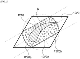
- the cooling holes 1220 a are formed at equal intervals along an imaginary line 1220 b ( 1221 b and/or 1222 b ) which is spaced apart from and surrounds the airfoil 1210 .
- the inner cooling holes 1221 a may be formed along an inner imaginary line 1221 b , which is spaced apart from and surrounds the perimeter (footprint) of the airfoil 1210 and which occurs on the airfoil-side surface of the inner shroud 1221 .
- outer cooling holes 1222 a may be formed along an outer imaginary line 1222 b , which is spaced apart from and surrounds the perimeter (footprint) of the airfoil 1210 and which occurs on the airfoil-side surface of the outer shroud 1222 .
- FIGS. 3 and 4 is a view from the airfoil 1210 .
- the cooling holes 1220 a are formed in each of the shrouds 1220 .
- the angle formed by the airfoil 1210 and an adjacent airfoil 1210 is measured and an optimal angle is calculated according to the specifications of the gas turbine 10 to be designed, with respect to the same stage.
- the vane 1200 is installed to the casing 1100 by removing an excess portion of the shroud 1220 (e.g., a portion interfere with an adjacent shroud 1220 ) and then inserting the outer shroud 1222 onto the inner peripheral surface of the casing 1100 .
- an excess portion of the shroud 1220 e.g., a portion interfere with an adjacent shroud 1220
- cooling holes 1220 a were to be irregularly formed in the shroud 1220 rather than along the imaginary line 1220 b , the already formed cooling holes 1220 a might be unintentionally removed from the shroud 1220 along with the intentional removal of the excess portion of the shroud 1220 .
- the cooling holes 1220 a are formed along the imaginary line 1220 b , the cooling holes 1220 a cannot be removed even though a portion of the shroud 1220 is removed along line “A-A” or line “B-B” as illustrated in FIGS. 3 and 4 .
- the imaginary line 1220 b may form an ellipse that is tangent to each of four surface edges of the shroud 1220 , with respect to one or both of the airfoil-side surfaces of the inner and outer shrouds 1221 and 1222 .
- the major axis of the ellipse may be aligned in the longitudinal direction of the airfoil 1210 and the minor axis of the ellipse may be aligned in the thickness direction of the airfoil 1210 .
- the imaginary line 1220 b may correspond to an outline of the figure formed by a combination of two circles and two line segments, which occur on one or both of the airfoil-side surfaces of the inner and outer shrouds 1221 and 1222 .
- the imaginary line 1220 b may be an outline of the figure formed by a first circle tangent to two adjacent edges of the surface edges of the shroud 1220 , a second circle tangent to the two other adjacent edges, and two line segments, each of which is circumscribed about the first and second circles.
- the two segments are each circumscribed about the first and second circles so as not to cross the airfoil 1210 , that is, so as not to intersect with each other between the first circle and the second circle.
- the outline refers to a periphery of the figure formed by arcs of the first and second circles, excluding the portion of the circle occurring between the two line segments, and the two line segments, which respectively connect the adjacent-edge tangent points of the first and second circles.
- the imaginary line 1220 b may correspond to an outline of the figure bounded by a portion of a circle around the center of gravity G of the shroud 1220 and a pair of straight lines drawn through the circle, which occur on one or both of the airfoil-side surfaces of the inner and outer shrouds 1221 and 1222 .
- the imaginary line 1220 b may correspond to an inner line of the figure formed by a circle, which is formed around the center of gravity G of the shroud 1220 and the radius of which is defined as the shortest among distances between the center of gravity G and the respective vertices of the shroud 1220 , and a pair of straight lines which are parallel to the longest among lines connecting the center of gravity G and the respective vertices of the shroud 1220 while passing through the points at which the circle meets the edges of the shroud 1220 .
- the inner line corresponds to an outline of the figure formed by two line segments made by excluding straight lines present outside the circle and two arcs made by excluding a portion of the circle present outside the surface of the shroud 1220 .
- the surface of the shroud 1220 does not form a point symmetry figure, that is, if the surface edges of the shroud 1220 are not symmetrical with respect to the center of gravity G of the shroud 1220 , a plurality of straight lines, which are parallel to the longest one of the line segments made by connecting the center of gravity G of the surface of the shroud 1220 to one of the vertices of the surface of the shroud 1220 , and passing through the points at which the circle meets the edge of the surface of the shroud 1220 , may be present at each of both sides with the center of gravity G interposed therebetween.
- the inner line corresponds an outline of the figure formed by two line segments made by excluding straight lines present outside the circle and two arcs made by excluding a portion present outside the two line segments.
- the inclination of the airfoil 1210 to an adjacent airfoil 1210 may vary with each drive specification of the gas turbine 10 . Accordingly, by selecting an appropriate type suitable for the inclination of the airfoil 1210 from among the various types of imaginary lines 1220 b , it is possible to minimize the number of cooling holes 1220 a to be removed or rearranged when the vane 120 is installed to the inner peripheral surface of the casing 1100 .
- the shroud 1220 may further have auxiliary cooling holes 1220 c in addition to the cooling holes 1220 a .
- the auxiliary cooling holes 1220 c are formed at a portion between the imaginary line 1220 b and the airfoil 1210 in the shroud 1220 .
- the auxiliary cooling holes 1220 c enable compressed air to be injected onto the surface of the airfoil 1210 to more effectively cool the surface of the airfoil 1210 .
- cooling holes 1220 a ( 1221 a and/or 1222 a ) along with the removal of an excess portion of the shroud 1220 , since the cooling holes 1220 a are formed along the various types of imaginary lines 1220 b ( 1221 b and/or 1222 b ), and to enhance productivity of the gas turbine since there is no need to rearrange the cooling holes 1220 a according to the rotation of the shroud 1220 .
Abstract
Description
Claims (11)
Applications Claiming Priority (2)
| Application Number | Priority Date | Filing Date | Title |
|---|---|---|---|
| KR10-2017-0121200 | 2017-09-20 | ||
| KR1020170121200A KR101955115B1 (en) | 2017-09-20 | 2017-09-20 | Turbine vane, turbine and gas turbine comprising the same |
Publications (2)
| Publication Number | Publication Date |
|---|---|
| US20190085769A1 US20190085769A1 (en) | 2019-03-21 |
| US10995668B2 true US10995668B2 (en) | 2021-05-04 |
Family
ID=65719208
Family Applications (1)
| Application Number | Title | Priority Date | Filing Date |
|---|---|---|---|
| US16/038,181 Active US10995668B2 (en) | 2017-09-20 | 2018-07-18 | Turbine vane, turbine, and gas turbine including the same |
Country Status (2)
| Country | Link |
|---|---|
| US (1) | US10995668B2 (en) |
| KR (1) | KR101955115B1 (en) |
Citations (4)
| Publication number | Priority date | Publication date | Assignee | Title |
|---|---|---|---|---|
| KR200174662Y1 (en) | 1996-10-09 | 2000-04-01 | 유무성 | Gas turbine |
| JP2008057537A (en) | 2006-08-29 | 2008-03-13 | General Electric Co <Ge> | Nozzle singlet for manufacturing nozzle segment used in turbine engine, and gas turbine engine |
| US20120177479A1 (en) * | 2011-01-06 | 2012-07-12 | Gm Salam Azad | Inner shroud cooling arrangement in a gas turbine engine |
| US20180128113A1 (en) * | 2016-11-04 | 2018-05-10 | General Electric Company | Airfoil assembly with a cooling circuit |
-
2017
- 2017-09-20 KR KR1020170121200A patent/KR101955115B1/en active IP Right Grant
-
2018
- 2018-07-18 US US16/038,181 patent/US10995668B2/en active Active
Patent Citations (4)
| Publication number | Priority date | Publication date | Assignee | Title |
|---|---|---|---|---|
| KR200174662Y1 (en) | 1996-10-09 | 2000-04-01 | 유무성 | Gas turbine |
| JP2008057537A (en) | 2006-08-29 | 2008-03-13 | General Electric Co <Ge> | Nozzle singlet for manufacturing nozzle segment used in turbine engine, and gas turbine engine |
| US20120177479A1 (en) * | 2011-01-06 | 2012-07-12 | Gm Salam Azad | Inner shroud cooling arrangement in a gas turbine engine |
| US20180128113A1 (en) * | 2016-11-04 | 2018-05-10 | General Electric Company | Airfoil assembly with a cooling circuit |
Also Published As
| Publication number | Publication date |
|---|---|
| KR101955115B1 (en) | 2019-03-06 |
| US20190085769A1 (en) | 2019-03-21 |
Similar Documents
| Publication | Publication Date | Title |
|---|---|---|
| KR102126882B1 (en) | Nozzle assembly, combustor and gas turbine including the same | |
| US8444387B2 (en) | Seal plates for directing airflow through a turbine section of an engine and turbine sections | |
| US11591922B2 (en) | Ring segment and gas turbine including the same | |
| KR102226741B1 (en) | Ring segment, and turbine including the same | |
| KR101997979B1 (en) | Blade airfoil, turbine and gas turbine comprising the same | |
| US11248792B2 (en) | Combustor and gas turbine including the same | |
| US10865656B2 (en) | Turbine blade ring segment, and turbine and gas turbine including the same | |
| US10947862B2 (en) | Blade ring segment for turbine section, turbine section having the same, and gas turbine having the turbine section | |
| CN100549366C (en) | The turbine stator protective gear | |
| US11655716B2 (en) | Cooling structure for trailing edge of turbine blade | |
| US10995668B2 (en) | Turbine vane, turbine, and gas turbine including the same | |
| US11401826B2 (en) | Stator structure and gas turbine having the same | |
| KR101955116B1 (en) | Turbine vane, turbine and gas turbine comprising the same | |
| EP3456922A1 (en) | Turbine blade with cooling structure, turbine including same turbine blade, and gas turbine including same turbine | |
| US10851673B2 (en) | Turbine stator, turbine, and gas turbine including the same | |
| KR102141998B1 (en) | Blade shroud, turbine and gas turbine comprising the same | |
| US11499440B2 (en) | Turbine vane and gas turbine including the same | |
| KR102510535B1 (en) | Ring segment and turbo-machine comprising the same | |
| GB2420156A (en) | Heat transfer arrangement | |
| KR102307577B1 (en) | Internal Cooling Structure for Turbine Blade of Turbine Engine | |
| US20230417144A1 (en) | Turbine blade and gas turbine including the same | |
| KR101937589B1 (en) | Turbine blade of turbine and turbine vane of turbine and turbine and gas turbine comprising the same | |
| KR102062530B1 (en) | Burner Having Transition Piece With Improving Pathway Structure, And Gas Turbine Having The Same |
Legal Events
| Date | Code | Title | Description |
|---|---|---|---|
| AS | Assignment |
Owner name: DOOSAN HEAVY INDUSTRIES & CONSTRUCTION CO., LTD, K Free format text: ASSIGNMENT OF ASSIGNORS INTEREST;ASSIGNOR:KIM, JIN UK;REEL/FRAME:046376/0141 Effective date: 20180628 Owner name: DOOSAN HEAVY INDUSTRIES & CONSTRUCTION CO., LTD, KOREA, REPUBLIC OF Free format text: ASSIGNMENT OF ASSIGNORS INTEREST;ASSIGNOR:KIM, JIN UK;REEL/FRAME:046376/0141 Effective date: 20180628 |
|
| FEPP | Fee payment procedure |
Free format text: ENTITY STATUS SET TO UNDISCOUNTED (ORIGINAL EVENT CODE: BIG.); ENTITY STATUS OF PATENT OWNER: LARGE ENTITY |
|
| STPP | Information on status: patent application and granting procedure in general |
Free format text: DOCKETED NEW CASE - READY FOR EXAMINATION |
|
| STPP | Information on status: patent application and granting procedure in general |
Free format text: NON FINAL ACTION MAILED |
|
| STPP | Information on status: patent application and granting procedure in general |
Free format text: RESPONSE TO NON-FINAL OFFICE ACTION ENTERED AND FORWARDED TO EXAMINER |
|
| STPP | Information on status: patent application and granting procedure in general |
Free format text: FINAL REJECTION MAILED |
|
| STPP | Information on status: patent application and granting procedure in general |
Free format text: RESPONSE AFTER FINAL ACTION FORWARDED TO EXAMINER |
|
| STPP | Information on status: patent application and granting procedure in general |
Free format text: ADVISORY ACTION MAILED |
|
| STPP | Information on status: patent application and granting procedure in general |
Free format text: DOCKETED NEW CASE - READY FOR EXAMINATION |
|
| STPP | Information on status: patent application and granting procedure in general |
Free format text: NON FINAL ACTION MAILED |
|
| STPP | Information on status: patent application and granting procedure in general |
Free format text: DOCKETED NEW CASE - READY FOR EXAMINATION |
|
| STPP | Information on status: patent application and granting procedure in general |
Free format text: NOTICE OF ALLOWANCE MAILED -- APPLICATION RECEIVED IN OFFICE OF PUBLICATIONS |
|
| STPP | Information on status: patent application and granting procedure in general |
Free format text: PUBLICATIONS -- ISSUE FEE PAYMENT RECEIVED |
|
| STPP | Information on status: patent application and granting procedure in general |
Free format text: PUBLICATIONS -- ISSUE FEE PAYMENT VERIFIED |
|
| STCF | Information on status: patent grant |
Free format text: PATENTED CASE |