EP1317593B1 - Improved self-raising platform assembly - Google Patents
Improved self-raising platform assembly Download PDFInfo
- Publication number
- EP1317593B1 EP1317593B1 EP01973868A EP01973868A EP1317593B1 EP 1317593 B1 EP1317593 B1 EP 1317593B1 EP 01973868 A EP01973868 A EP 01973868A EP 01973868 A EP01973868 A EP 01973868A EP 1317593 B1 EP1317593 B1 EP 1317593B1
- Authority
- EP
- European Patent Office
- Prior art keywords
- platform
- mast
- hook
- modular
- platform assembly
- Prior art date
- Legal status (The legal status is an assumption and is not a legal conclusion. Google has not performed a legal analysis and makes no representation as to the accuracy of the status listed.)
- Expired - Lifetime
Links
Images







Classifications
-
- B—PERFORMING OPERATIONS; TRANSPORTING
- B66—HOISTING; LIFTING; HAULING
- B66B—ELEVATORS; ESCALATORS OR MOVING WALKWAYS
- B66B9/00—Kinds or types of lifts in, or associated with, buildings or other structures
- B66B9/16—Mobile or transportable lifts specially adapted to be shifted from one part of a building or other structure to another part or to another building or structure
- B66B9/187—Mobile or transportable lifts specially adapted to be shifted from one part of a building or other structure to another part or to another building or structure with a liftway specially adapted for temporary connection to a building or other structure
-
- B—PERFORMING OPERATIONS; TRANSPORTING
- B66—HOISTING; LIFTING; HAULING
- B66F—HOISTING, LIFTING, HAULING OR PUSHING, NOT OTHERWISE PROVIDED FOR, e.g. DEVICES WHICH APPLY A LIFTING OR PUSHING FORCE DIRECTLY TO THE SURFACE OF A LOAD
- B66F1/00—Devices, e.g. jacks, for lifting loads in predetermined steps
- B66F1/02—Devices, e.g. jacks, for lifting loads in predetermined steps with locking elements, e.g. washers, co-operating with posts
- B66F1/04—Devices, e.g. jacks, for lifting loads in predetermined steps with locking elements, e.g. washers, co-operating with posts the posts being toothed
- B66F1/08—Devices, e.g. jacks, for lifting loads in predetermined steps with locking elements, e.g. washers, co-operating with posts the posts being toothed and the devices being operated by fluid pressure
-
- B—PERFORMING OPERATIONS; TRANSPORTING
- B66—HOISTING; LIFTING; HAULING
- B66F—HOISTING, LIFTING, HAULING OR PUSHING, NOT OTHERWISE PROVIDED FOR, e.g. DEVICES WHICH APPLY A LIFTING OR PUSHING FORCE DIRECTLY TO THE SURFACE OF A LOAD
- B66F11/00—Lifting devices specially adapted for particular uses not otherwise provided for
- B66F11/04—Lifting devices specially adapted for particular uses not otherwise provided for for movable platforms or cabins, e.g. on vehicles, permitting workmen to place themselves in any desired position for carrying out required operations
-
- E—FIXED CONSTRUCTIONS
- E04—BUILDING
- E04G—SCAFFOLDING; FORMS; SHUTTERING; BUILDING IMPLEMENTS OR AIDS, OR THEIR USE; HANDLING BUILDING MATERIALS ON THE SITE; REPAIRING, BREAKING-UP OR OTHER WORK ON EXISTING BUILDINGS
- E04G1/00—Scaffolds primarily resting on the ground
- E04G1/18—Scaffolds primarily resting on the ground adjustable in height
- E04G1/20—Scaffolds comprising upright members and provision for supporting cross-members or platforms at different positions therealong
Definitions
- the present invention relates to several improvements to the basic structure of a scaffolding hereinafter called “platform assembly”, which is designed to be self-standing or to be erected close to a building wall in order to help workmen to construct, repair or otherwise work on this wall.
- the invention relates to improvements made to a self-raising platform assembly comprising at least one mast along which a platform may be moved up or down by means of a lifting mechanism including a hydraulically operated ram extendable and retractable along the mast.
- a lifting mechanism including a hydraulically operated ram extendable and retractable along the mast.
- Platform assemblies made of modular elements that can be erected close to a building structure so those workmen can work on the same, are well known and commonly used in the construction area.
- the main object of the invention is to satisfy the above need by providing an improved platform assembly of the type disclosed in the above prior art references, which improved platform assembly is very strong, reliable, easy to assemble and to adapt to the user's requirements, end, of course, very safe.
- the platform assembly according to the invention is of the type comprising:
- the platform assembly of the above type is characterized in that the lifting mechanism includes:
- the platform assembly according to the invention may also comprise one or more of the following features (a) to (d):
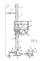
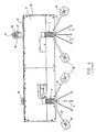
- the improved platform assembly 1 according to the first preferred embodiment of the invention as shown in Figures 1 to 11, comprises at least one and preferably two or more horizontally spaced apart masts 3,5 each made of modular sections 7 devised to be detachably connected to each other in end-to-end relationship.
- Each mast 3,5 has a base 9 that is intended to be positioned onto the ground close to the building structure "S" (see Figure 3) which is to be erected or repaired. Whenever such is required, tie rods 11 may be installed to connect the masts to the structure (see again Figure 3).
- An horizontal platform 13 is mounted onto the masts 3,5 in such a manner as to be easily movable up and down along the same.
- the platform 13 comprises a frame 15 formed with a number of sleeves 17,19 corresponding to the number of the masts 3,5.
- Each sleeve is devised to receive and slide along a corresponding tower.
- the sleeves have their front faces that are left open so as to allow the platform 13 to be moved up or down along the masts without having to remove the tie rods 11.
- a floor 21 and safety guard rails 23 are mounted onto the frame 15.
- a lifting mechanism is provided to move the platform 13 up and down along the masts 3,5 whenever such is required.
- This lifting mechanism is mounted onto the platform and operable from the same, thereby avoiding the necessity of extra equipment like a crane.
- the present invention essentially lies in several improvements that have been made to the basic structure disclosed hereinabove.
- Each of these improvements is structurally independent from the others and its relative importance as compared to the others essentially depends on the user's requirement.
- the improved platform assembly according to the invention may contain only one of these improvements even though, in practice, it should preferably contain several of them, and, even more preferably, all of them. For the very same reason as above, no importance should also be given to the order in which said improvements will now be described.
- a first one of these improvements lies in the structure of the base 9 of each mast.
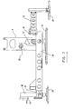
- each base 9 extends upwardly on top of a large supporting plate 25 which is itself connected to the bottom end of a vertically adjustable implement jack 27 embedded within the base 9.
- the jack 27 which is preferably mechanically driven via a gear box 28 can be actuated to adjust the position of the corresponding mast relative to the ground on which the plate 25 is laid down and thus to compensate any defects in the positioning and/or balancing of the platform.
- each base 9 is rigidly connected to an external frame 29 made of bars on which at least one and preferably two or more stabilizer arms 33, 37 are mounted.
- each stabilizer arm 33 is connected by means of a pin 35 to one end of one of the bars forming the external frame 29.
- each stabilizer arm 33, 37 has a supporting plate 39 in contact with the ground.
- the plate 39 of the stabilizer arm 37 is mounted onto a retractable jack 38 that can be manually or electrically actuated via a gear box 40.
- the bases 9 are completely separate from each other. Such is interesting inasmuch as masts 3, 5 may then be positioned at levels different from each other. Such gives a maximum versatility to assembly and position the whole assembly.
- a second improvement made to the basic structure of the platform assembly 1 disclosed hereinabove lies in the structure of the modular sections 7 of the masts 3, 5.
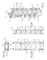
- each mast section 7 is of parallepipedic shape and made of a metal plate 61 that is folded and welded to form a tube of rectangular cross-section.
- Large holes 63 are made in the sides of the tube formed by the plate 61 to define equally spaced part steps and thus give a "ladder" shape to the tube. Such holes can be cut with a laser beam in a very easy and efficient way.
- Transverse bars 65 are welded onto the four sides of the tube within the same at the level of each step to reinforce the same.
- each mast section 7 is provided at one end with a set of guiding bars 55 of rectangular cross-section that are positioned to fit into the corners of the opposite end of the tube of an adjacent mast section.
- Each bar 55 is provided with a hole 57 that is positioned to be aligned with a corresponding hole 59 made in the tube of the adjacent mast section when these two sections are connected end-to-end.
- the holes 59 made in the plate 61 forming the tube of each section 7 may be reinforced with a hollowed plate to prevent any unwanted wear that could generate a slack when connected with bolts.
- a pair of reinforcing L-shaped transverse bars 49 are fixed to the tube close to the upper and lower ends thereof. These bars 49 are provided with holes 51 in their vertical and horizontal portions. These holes 51 permit adjacent mast sections 9 to be rigidly connected by means of upwardly or transversally extending bolts after these adjacent sections have been installed end-to-end and/or in parallel relationship (as shown in Figure 15). Such permits to make the mast stronger and safer inasmuch as once they are so connected to each other, the risk of shearing of the bolts inserted into the holes 57, 59 is substantially reduced.
- a third improvement made to the basic structure of the platform assembly 1 disclosed hereinabove lies in the structure and operation of the lifting mechanism used to move the platform 13 up and down along the masts 3, 5.
- a lifting mechanism comprising a pair of anchoring members pivotably carried by the platform adjacent each mast, and alternatively and successively engageable with the steps of the masts so as to suspend the platform at different levels (see claim 1 of this patent).
- One of these anchoring members consists of a power-actuated member extensible and retractable along the adjacent mast relative to the platform through a stroke equal to the vertical spacing between two adjacent steps.
- the other anchoring member consists of a hook. Both of these anchoring members are biased against the mast to ensure their automatic engagement with the adjacent steps when the platform is raised or lowered by the extensible members.
- the power actuated member consists of a double acting hydraulic cylinder that extends upwardly at an angle so as to bear onto the tower by gravity and has a lower end pivotably connected to the platform frame and an upper end with a hook shaped to catch the transverse bars forming the steps of the adjacent mast.
- lifting of the platform is achieved with a mechanism which is very similar to the one disclosed hereinabove but which works in a completely different way inasmuch as due to the way the main cylinder is mounted, the platform is lifted up and thus raised only when the piston of the main cylinder is extended. In other words, in operation, the main cylinder does not pull up but rather pushes up the platform.
- the lifting mechanism of the improved platform assembly comprises, adjacent each mast, a set of anchoring members including:
- a first back cylinder 83 is provided to apply a lateral pressure onto the cylinder 73 and thus to force the hook(s) 77 connected to the piston 75 to engage the corresponding step of the mast.
- Other back cylinder(s) 84 are provided to tilt the hook-shaped bars 79, 81 about their pivot axes at their upper ends to force said bars 79, 81 to engage the other step of the mast.
- two guiding rods 85 are fixed to the piston 75 of the main cylinder so as to slide in parallel relationship with respect to the external surface of the main cylinder 73 when the same is actuated.
- Such guiding rods ensure that the at least one hook 77 be permanently held in operation position by preventing the piston 75 from rotating about its own axis and thus ensure that the hook (s) 77 are always properly positioned with respect to the mast.
- the guiding rod(s) 85 may have recesses 87 made in their surface at given intervals in order to give signals to a control machine upon contact with a proximity switch (not shown) and thus ensure that proper pressure is supplied to the back cylinder 83 depending on the position of the piston 75 of the main cylinder 73.
- the platform 3 is lifted up when the piston 75 is pushed down. Since the pressure is applied to the whole surface of the piston head that is opposite to the piston rod, the efficiency of the lifting mechanism is improved, in particular, the lifting speed is increased.
- the hook(s) 77 and the hook-shaped bars 79, 81 are pushed out while they pass over the transverse bars 85 but they come back to these bars in order to engage the same as soon as they extend on top of it.
- the control system must also include means to actuate the back cylinders 83, 84 to force the hook(s) 77 and the hook-shaped bars 79, 81 to retract in order to disengage the steps of the mast when one wants to lower the platform along the tower. Such a retraction must of course be carried out in an alternate and successive manner to ensure that the platform be always held either by the hook(s) 77 or by the hook-shaped bars 79, 81.
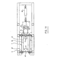
- the lifting assembly may comprise one single hook 77 or two of them (as shown in Figure 11) pivotably attached in parallel relationship to the bottom end of the piston of the main cylinder. It is also worth noting that the way each hook 77 is shaped, is important. Indeed, the hook 77 must have a finger 91 (see Figure 10) sized and shaped to engage the steps of the mast. It must also have an edge 93 projecting down below the finger 91 so as to bear against the adjacent side wall of mast and the end of the piston 75 and thus prevent the hook 77 from rotating upside down. In other words, the hook 77 must be designed to be self-locking.
- a fourth improvement made to the basic structure of the platform assembly 1 disclosed hereinabove lies in the way the sleeves 17 are slidably mounted onto the corresponding masts 3, 5.
- a fifth improvement made to the basic structure of the platform assembly 1 disclosed hereinabove lies in the way the horizontal platform 13 is made.
- the platform comprises a frame 15 formed with one or more sleeves 17, 19 devised to receive the corresponding masts 3, 5.
- the frame 15 supports a floor 21 and safety guard rails 23 that are preferably detachably mounted.
- the posts of the guard rails 23 are devised to be slid and locked into vertical tubes that are parts of the frame 15 and extend in line with holes in the floor 21. Locking of the posts within the corresponding tubes can be achieved with C-shaped pins or any other suitable means.
- the platform 13 may be for example 24 feet (7.3 meters) long and 6 feet (1.8 meters) wide.
- Its frame 15 can be made of hollow tubes extending longitudinally, transversely and at angles. These tubes are welded to each other. Their lengths and positioning are selected to give to the platform 13 an isosceles trapezium shape when seen in vertical transverse cross-section.
- additional modular platform segments 101, 103 are provided to increase the width and/or length of the platform 13 whenever such is required. Extension of the length of the platform may be necessary when the building structure to be erected or repaired is very long. Extension of the width of the platform may also be required when one wants an easy access or contact with the building, structure and the masts 3, 5 are not close enough to allow it (see Figures 15a and 15b).
- the segments 101, 103 may be 8 feet (2.4 meters) and 4 feet (1.2 meter) long, respectively.
- the segments 101. 103 are of the same transverse isosceles trapezium shape on the platform 13. As a result, they can be connected either in line with the platform 13, as is shown in Figure 12, or perpendicularly thereto after having been turned upside down, as is shown in Figure 13.
- at least some of the segments like the one numbered 103 in Figure 13 must be provided with floors on the lower surfaces of their frames.
- connection between the frames of the main platform 13 and those of the segments 101, 103 can be easily achieved by means of bars 105 (see Figure 14) that are devised to be inserted into hollow ends of adjacent elements of the frames to be connected, and then be locked in place by means of bolts 107 inserted into holes 109, 110 made in the bars and the element of the frames in which said bars are devised to be inserted (see Figure 14).
- the bars 105 have holes 109 at different distances from each other to allow connection of the adjacent elements in end-to-end relationship with their ends either in contact or in slightly spaced part position.
- Such a "slack" makes it possible to adjust the horizontal orientation of the segments 101, 103 with respect to the frame 15, with each segment at a slightly upwards or downwards angle.
- the improved platform assembly 1 may comprise one or more masts.
- the platform assembly comprises one single "double size" mast 113 made of two adjacent masts 3, 5 of the type used in the first embodiment disclosed hereinabove.
- the base 119 of the mast 113 and sleeve 115 on the frame of its platform has to be adapted accordingly.
Landscapes
- Engineering & Computer Science (AREA)
- Structural Engineering (AREA)
- Mechanical Engineering (AREA)
- Civil Engineering (AREA)
- Life Sciences & Earth Sciences (AREA)
- Architecture (AREA)
- Geology (AREA)
- Automation & Control Theory (AREA)
- Physics & Mathematics (AREA)
- Fluid Mechanics (AREA)
- Transportation (AREA)
- Ladders (AREA)
- Forklifts And Lifting Vehicles (AREA)
- Platform Screen Doors And Railroad Systems (AREA)
- Bridges Or Land Bridges (AREA)
Abstract
Description
- the structure of the base of the mast(s);
- the structure of the mast(s);
- the structure and operation of the lifting mechanism;
- the way the platform is guided along the tower(s); and
- the structure of the platform itself.
- a main
hydraulic cylinder 73 having anupper end 74 pivotably connected to the structure of thesleeve 17 of the platform and a lower end from which projects apiston 75 having a free end with at least onehook 77 pivotably mounted thereto for engagement with one of the steps made in thesections 7 of the mast; and - at least one and preferably two hook-shaped
bars upper ends 80 pivotably connected to the structure of thesleeve 17 and their bottom ends shaped and devised to engage and hook onto another step of the mast.
Claims (6)
- A platform assembly (1) of the type comprising:characterized in that said lifting mechanism comprises;at least one mast (3, 5, 113) made of modular sections (7) devised to be detachably connected to each other in end-to-end relationship, each of said at least one mast being intended to be positioned onto the ground, each of said modular sections (7) being devised to form equally spaced apart steps and be used as a ladder;a horizontal platform (13) mounted onto said at least one mast in such a manner as to be easily movable up and down along the same, said platform including a frame (15) formed with at least one sleeve (17, 19) through which a corresponding one of said at least one mast extends, said platform also including a floor (21); anda lifting mechanism to move the platform (13) up and down along said at least one mast, said lifting mechanism being mounted onto the platform and operable from the same;whereby the platform is lifted up when the piston of the main cylinder is pushed down, thereby improving the efficiency and speed of the whole mechanism.a main hydraulic cylinder (73) having an upper end (74) pivotably connected to the sleeve (17, 19) of the platform and a lower end from which projects a piston (75) having a free end with at least one hook (77) pivotably mounted thereto for engagement with the steps equally spaced apart along the corresponding mast,at least one hook-shaped bar (79, 81) having an upper end (80) pivotably connected to the platform and a lower end shaped and devised to engage and hook onto the steps or the corresponding mast; andat least two back cylinders (83, 84) to apply a lateral pressure onto the main cylinder (73) and to actuate the hook-shaped bar(s) (79, 81), so as to force them to engage the steps or to retract from the same in alternance;
- The improved platform of claim 1, characterized in that said assembly also comprises:additional modular platform segments (101, 103) detachably connectable to the frame (15) of the platform (13) to increase both the length and the width of said platform (13) wherever such is required.
- The improved platform assembly of claim 1 or 2, characterized in that each of the modular sections (7) of each of said at least one mast (3, 5, 113) is made of a metal plate (61) folded and welded to form a tube of rectangular cross-section in which large holes (63) are made to form said steps and give a ladder-shape to the section, said tube being reinforced with transverse bars (49).
- The improved platform assembly of claim 3, characterized in that each of the modular sections (7) is connected to the adjacent modular section(s) by means of upwardly extending bolts and has a set of longitudinal guiding bars (55) welded at one end thereof to allow positioning and fixation of said modular sections (7) onto each other in end-to-end relationship.
- The improved platform assembly of any one of claims 1 to 4, characterized in that each of said at least one mast has a base (9) extending upwardly on top of a large supporting plate (25) connected to an implement jack (27) embedded into said base, said base (9) also having an external frame (29) on which is connected at least one stabilizer arm (33, 37), whereby height adjustment and lateral stability of the platform assembly are substantially improved.
- The improved platform assembly of any one of claims 1 to 5, characterized in that each of said at least one sleeve (17, 19) of the platform (13) is held in position and guided along the corresponding mast by means of L-shaped pads (97) made of ultra high molecular weight plastic material, said pads contacting and sliding along corners of the corresponding mast when the platform (13) moves up or down, whereby a smooth and reliable motion is achieved.
Applications Claiming Priority (3)
| Application Number | Priority Date | Filing Date | Title |
|---|---|---|---|
| CA002317987A CA2317987A1 (en) | 2000-09-11 | 2000-09-11 | Improved self-raising platform assembly |
| CA2317987 | 2000-09-11 | ||
| PCT/CA2001/001273 WO2002020919A1 (en) | 2000-09-11 | 2001-09-05 | Improved self-raising platform assembly |
Publications (2)
| Publication Number | Publication Date |
|---|---|
| EP1317593A1 EP1317593A1 (en) | 2003-06-11 |
| EP1317593B1 true EP1317593B1 (en) | 2005-07-06 |
Family
ID=4167079
Family Applications (1)
| Application Number | Title | Priority Date | Filing Date |
|---|---|---|---|
| EP01973868A Expired - Lifetime EP1317593B1 (en) | 2000-09-11 | 2001-09-05 | Improved self-raising platform assembly |
Country Status (9)
| Country | Link |
|---|---|
| US (2) | US6883643B2 (en) |
| EP (1) | EP1317593B1 (en) |
| CN (1) | CN1196841C (en) |
| AT (1) | ATE299215T1 (en) |
| AU (2) | AU9353401A (en) |
| CA (1) | CA2317987A1 (en) |
| DE (1) | DE60111852T2 (en) |
| MX (1) | MXPA03002063A (en) |
| WO (1) | WO2002020919A1 (en) |
Families Citing this family (62)
| Publication number | Priority date | Publication date | Assignee | Title |
|---|---|---|---|---|
| IL158855A0 (en) * | 2001-05-31 | 2004-05-12 | Azran Construction Automation | A scaffold |
| CA2499994C (en) * | 2002-09-23 | 2012-07-10 | Verion, Inc. | Abuse-resistant pharmaceutical compositions |
| FR2872841A1 (en) * | 2004-07-12 | 2006-01-13 | Fixator Soc Par Actions Simpli | PLATFORM SUPPORT DEVICE FOR ELEVATION OF LOADS OR PEOPLE ALONG A WORK |
| FR2873672B1 (en) * | 2004-07-30 | 2008-02-01 | Xavier Lombard | LIFTING ASSEMBLY |
| US20070056802A1 (en) * | 2005-09-13 | 2007-03-15 | Joseph Taberah | Scaffolding |
| CN1967121B (en) * | 2005-11-16 | 2010-04-21 | 烟台鲁宝钢管有限责任公司 | Expansion rebuilding method for ring furnace |
| US7896133B2 (en) * | 2006-02-17 | 2011-03-01 | Jerry Castle | Self-elevating platform scaffolding |
| US20070204520A1 (en) * | 2006-03-01 | 2007-09-06 | Calleja Michael J | Self-elevating staging with rack-and-pinion posts |
| DE102006029653B4 (en) * | 2006-06-28 | 2009-02-12 | Doka Industrie Gmbh | Lifting platform and method for building a lifting platform |
| CA2592494A1 (en) * | 2007-06-12 | 2008-12-12 | Alden Heppner | Elevated observatory |
| CA2602739C (en) * | 2007-09-14 | 2016-04-12 | Joseph Taberah | Power lift system |
| US8167089B2 (en) * | 2008-01-15 | 2012-05-01 | Bennu Parts And Service, Inc. | Liftable scaffold |
| NO333125B1 (en) * | 2008-05-26 | 2013-03-11 | Noracon As | An access system, a method of mounting such a system, and a guide member, an elongated extruded profile and a support member for the access system |
| US20100096216A1 (en) * | 2008-10-17 | 2010-04-22 | Hekimo, S.R.O. | Scaffolding |
| JP5474522B2 (en) * | 2009-01-14 | 2014-04-16 | ギガフォトン株式会社 | Extreme ultraviolet light source system |
| US8046970B2 (en) * | 2009-04-03 | 2011-11-01 | Aluma Tower Company, Inc. | Unguyed telescoping tower |
| CN101586392B (en) * | 2009-04-13 | 2011-07-20 | 浙江鼎力机械有限公司 | Mast climbing type aerial working platform |
| GB2478612B (en) * | 2010-07-28 | 2012-02-22 | Bersche Rolt Ltd | Access systems |
| IT1401371B1 (en) | 2010-08-05 | 2013-07-18 | Gru Dalbe Srl | SELF-LIFTING SUPPORT STRUCTURE FOR BUILDING. |
| CN101955142A (en) * | 2010-08-17 | 2011-01-26 | 启东大同电机有限公司 | Transmission mechanism of aerial working platform |
| AU2012275327A1 (en) | 2011-06-29 | 2014-01-23 | Reechcraft, Inc. | Portable modular lift system |
| CN102926529B (en) * | 2011-08-11 | 2014-11-26 | 北京建筑工程学院 | Self-elevating scaffold provided with telescoping platforms for building construction |
| US8636112B2 (en) | 2011-08-31 | 2014-01-28 | Sky Climber, Llc | Safety lockout system |
| CN102359282B (en) * | 2011-10-23 | 2014-04-02 | 陈永兴 | Wall building and painting device |
| CN102987993A (en) * | 2012-10-31 | 2013-03-27 | 博宇(无锡)科技有限公司 | Lift type straight arm |
| CA2834094C (en) * | 2012-11-23 | 2019-08-20 | Fiducie Familiale Andre St-Germain | Self-contained, portable and self-supporting scaffolding kit |
| CN103011000B (en) * | 2012-12-25 | 2015-09-16 | 黄善同 | Detachable mobile elevator |
| US8726584B1 (en) * | 2013-03-15 | 2014-05-20 | Kontek Industries, Inc. | Mobile elevated building |
| CN103288015B (en) * | 2013-06-17 | 2015-09-09 | 南通四建装饰工程有限公司 | Rigid guideway horizontal electric suspension type nacelle device |
| US9347603B2 (en) | 2013-06-20 | 2016-05-24 | Taggart Global, Llc | Counterweight hoisting apparatus |
| CN104264958B (en) * | 2014-10-09 | 2016-04-27 | 浙江镜湖建设集团有限公司 | A kind of liftable equipment |
| CN104908883B (en) * | 2015-05-19 | 2018-03-09 | 浙江海洋学院 | A kind of extra large work ship auxiliary construct platform |
| KR101632385B1 (en) * | 2015-10-20 | 2016-06-21 | 주식회사 송산특수엘리베이터 | Super Sized Elevator Having Wind Protector of Cable for Manufacturing Large Vessel and Ocean Plant Equipment |
| CN105421738B (en) * | 2015-11-30 | 2017-12-08 | 中国一冶集团有限公司 | Traveling centering |
| NO341549B1 (en) * | 2016-03-07 | 2017-12-04 | Helijo As | A foldable platform lift |
| CN106337558B (en) * | 2016-08-31 | 2018-07-03 | 赣州市嘉班钢模有限公司 | A kind of double lead beam slab controller |
| CN106869473B (en) * | 2017-04-06 | 2019-07-09 | 北京建筑机械化研究院 | The liftable operation platform and its construction method of assembled architecture |
| CN108396951A (en) * | 2018-03-20 | 2018-08-14 | 芜湖成安建设工程有限公司 | A kind of tooling for construction |
| CN109469302B (en) * | 2018-12-28 | 2024-03-26 | 中冶天工集团天津有限公司 | Modular structure capable of quickly disassembling and assembling modular platform, construction method and dismantling method |
| US20200270107A1 (en) * | 2019-02-26 | 2020-08-27 | Hhi Corporation | Adjustable aircraft maintenance stand |
| JP7278863B2 (en) * | 2019-05-13 | 2023-05-22 | 光洋機械産業株式会社 | How to install a lifting scaffold |
| ES2804038B2 (en) * | 2019-07-30 | 2021-11-18 | Hws Concrete Towers S L | ANCHOR FOR SELF-CLIMBING STRUCTURE |
| CN110409781B (en) * | 2019-08-16 | 2021-04-27 | 马鞍山观点信息科技有限公司 | Operation table for indoor and outdoor decoration operation construction and use method thereof |
| CN110936124A (en) * | 2019-12-09 | 2020-03-31 | 中车长江车辆有限公司 | Flexible assembling operation device for vehicle body |
| US20210261395A1 (en) * | 2020-02-20 | 2021-08-26 | John Stephen Lanphear | Low Profile Adjustable Height Operator Platform |
| CN111335607A (en) * | 2020-03-16 | 2020-06-26 | 李庆磊 | Building external climbing type building construction operation platform |
| CN112010147A (en) * | 2020-07-22 | 2020-12-01 | 上海二十冶建设有限公司 | Rapid installation method of large-scale unit auxiliary equipment in limited space |
| CN112411976A (en) * | 2020-12-02 | 2021-02-26 | 山东耀华特耐科技有限公司 | Lifting system is carried with refractory material safety to job site |
| CN112900820B (en) * | 2021-01-16 | 2022-04-01 | 中铁一局集团有限公司 | Scaffold for building construction |
| CN113137042B (en) * | 2021-04-23 | 2022-06-07 | 李喜海 | Automatic bottom-lifting type lifting platform and construction method thereof |
| CN113216586A (en) * | 2021-05-25 | 2021-08-06 | 南通永楠建设工程有限公司 | Adjustable high-stability safety building platform for interior decoration |
| CN113622722B (en) * | 2021-07-02 | 2023-02-28 | 河南工业贸易职业学院 | High-reliability stage lifting system controlled by computer |
| CN113757020A (en) * | 2021-08-31 | 2021-12-07 | 国网新源控股有限公司 | A pump-turbine maintenance work platform with ring-hoisting function |
| CN113845071B (en) * | 2021-09-14 | 2024-09-10 | 湖南中联重科应急装备有限公司 | Work bucket and fire truck |
| CN114182940A (en) * | 2021-12-03 | 2022-03-15 | 上海市建筑装饰工程集团有限公司 | Movable lifting truss vehicle |
| CN114232962B (en) * | 2021-12-20 | 2023-03-28 | 岳阳长岭炼化方元建设监理咨询有限公司 | Novel mobile operation platform |
| CN114737816B (en) * | 2022-04-22 | 2023-07-28 | 中国建筑第二工程局有限公司 | Mast dismantling method for lifting high-altitude operation platform by adopting shoulder pole beam |
| CN115199016B (en) * | 2022-08-22 | 2024-05-17 | 中铁一局集团建筑安装工程有限公司 | Large-section frame column operation construction platform |
| JP2024048117A (en) * | 2022-09-27 | 2024-04-08 | 鹿島建設株式会社 | Construction elevator |
| CN115743404A (en) * | 2022-11-17 | 2023-03-07 | 中交第三航务工程局有限公司 | Marine quick positioning and supporting device capable of automatically walking |
| CN116374913A (en) * | 2023-04-12 | 2023-07-04 | 扬州国网电力工具研发制造有限公司 | A mobile comprehensive power maintenance detection device |
| CN118478334B (en) * | 2024-07-15 | 2024-11-08 | 江苏海洋大学 | Welding platform for port crane assembly |
Family Cites Families (9)
| Publication number | Priority date | Publication date | Assignee | Title |
|---|---|---|---|---|
| US3323616A (en) * | 1965-10-22 | 1967-06-06 | Frank S Best | Mason's scaffold |
| US4294332A (en) * | 1979-04-13 | 1981-10-13 | Ready Delbert L | Scaffold with gear drive |
| US4293054A (en) * | 1980-05-19 | 1981-10-06 | Piat Impalcature Automatiche S.P.A. | Scaffolding for supporting lifting working bridges and platforms |
| US4809814A (en) * | 1988-04-01 | 1989-03-07 | St Germain Jean | Scaffolding |
| US5159993A (en) * | 1991-10-15 | 1992-11-03 | Gestion Des Brevets Fraco Limitee | Self-raising work platform assembly |
| US5271482A (en) * | 1992-06-05 | 1993-12-21 | Lowell Lift, Inc. | Electric light weight portable scaffolding |
| US5579865A (en) * | 1994-02-23 | 1996-12-03 | Butler; J. Frank | Scaffold |
| US5575591A (en) * | 1995-04-24 | 1996-11-19 | Vanderklaauw; Peter M. | Apparatus and method for a modular support and lifting system |
| US5746290A (en) * | 1995-07-27 | 1998-05-05 | Gestion De Brevets Fraco Ltee | Self erecting scaffolding |
-
2000
- 2000-09-11 CA CA002317987A patent/CA2317987A1/en not_active Abandoned
-
2001
- 2001-09-05 EP EP01973868A patent/EP1317593B1/en not_active Expired - Lifetime
- 2001-09-05 WO PCT/CA2001/001273 patent/WO2002020919A1/en not_active Ceased
- 2001-09-05 AU AU9353401A patent/AU9353401A/en active Pending
- 2001-09-05 CN CN01815453.0A patent/CN1196841C/en not_active Expired - Fee Related
- 2001-09-05 US US10/363,812 patent/US6883643B2/en not_active Expired - Fee Related
- 2001-09-05 DE DE60111852T patent/DE60111852T2/en not_active Expired - Fee Related
- 2001-09-05 MX MXPA03002063A patent/MXPA03002063A/en active IP Right Grant
- 2001-09-05 AT AT01973868T patent/ATE299215T1/en not_active IP Right Cessation
- 2001-09-05 AU AU2001293534A patent/AU2001293534B2/en not_active Ceased
-
2005
- 2005-04-26 US US11/114,830 patent/US7090051B2/en not_active Expired - Fee Related
Also Published As
| Publication number | Publication date |
|---|---|
| CN1455839A (en) | 2003-11-12 |
| EP1317593A1 (en) | 2003-06-11 |
| AU9353401A (en) | 2002-03-22 |
| AU2001293534B2 (en) | 2007-04-26 |
| CA2317987A1 (en) | 2002-03-11 |
| US7090051B2 (en) | 2006-08-15 |
| DE60111852D1 (en) | 2005-08-11 |
| US6883643B2 (en) | 2005-04-26 |
| US20040020717A1 (en) | 2004-02-05 |
| CN1196841C (en) | 2005-04-13 |
| WO2002020919A1 (en) | 2002-03-14 |
| ATE299215T1 (en) | 2005-07-15 |
| MXPA03002063A (en) | 2004-09-10 |
| US20050183905A1 (en) | 2005-08-25 |
| DE60111852T2 (en) | 2006-04-20 |
Similar Documents
| Publication | Publication Date | Title |
|---|---|---|
| US6883643B2 (en) | Self-raising platform assembly | |
| AU2001293534A1 (en) | Improved self-raising platform assembly | |
| US9410329B2 (en) | Lift unit for ascending and descending a scaffold | |
| EP1846631B1 (en) | Apparatus for use in the construction of buildings | |
| EP1373119B1 (en) | Tower crane device | |
| EP0766769B1 (en) | Scaffolding assembly | |
| US9133632B2 (en) | Platform support device for lifting loads or persons the height of a structure | |
| CA1174481A (en) | Climbing shuttering | |
| WO2012006694A1 (en) | Lift system for use in a scaffold | |
| CA2421184C (en) | Improved self-raising platform assembly | |
| CN113998616B (en) | Shed steel beam mounting method based on lifting vehicle | |
| CN212773641U (en) | Lifting type stair protection platform | |
| CN220224960U (en) | Construction platform | |
| CN221521967U (en) | Vertical transport lifting device | |
| EP3423390B1 (en) | A foldable platform lift | |
| CN118561183A (en) | A tower crane support and lifting device | |
| CN115897402A (en) | An integrated trolley for construction and protection of bridge guardrails | |
| PL104710B1 (en) | HYDRAULIC DEVICE FOR LIFTING AND LOWERING HEAVY LOADS |
Legal Events
| Date | Code | Title | Description |
|---|---|---|---|
| PUAI | Public reference made under article 153(3) epc to a published international application that has entered the european phase |
Free format text: ORIGINAL CODE: 0009012 |
|
| 17P | Request for examination filed |
Effective date: 20030310 |
|
| AK | Designated contracting states |
Designated state(s): AT BE CH CY DE DK ES FI FR GB GR IE IT LI LU MC NL PT SE TR |
|
| AX | Request for extension of the european patent |
Extension state: AL LT LV MK RO SI |
|
| GRAP | Despatch of communication of intention to grant a patent |
Free format text: ORIGINAL CODE: EPIDOSNIGR1 |
|
| GRAS | Grant fee paid |
Free format text: ORIGINAL CODE: EPIDOSNIGR3 |
|
| GRAA | (expected) grant |
Free format text: ORIGINAL CODE: 0009210 |
|
| AK | Designated contracting states |
Kind code of ref document: B1 Designated state(s): AT BE CH CY DE DK ES FI FR GB GR IE IT LI LU MC NL PT SE TR |
|
| PG25 | Lapsed in a contracting state [announced via postgrant information from national office to epo] |
Ref country code: LI Free format text: LAPSE BECAUSE OF FAILURE TO SUBMIT A TRANSLATION OF THE DESCRIPTION OR TO PAY THE FEE WITHIN THE PRESCRIBED TIME-LIMIT Effective date: 20050706 Ref country code: FI Free format text: LAPSE BECAUSE OF FAILURE TO SUBMIT A TRANSLATION OF THE DESCRIPTION OR TO PAY THE FEE WITHIN THE PRESCRIBED TIME-LIMIT Effective date: 20050706 Ref country code: BE Free format text: LAPSE BECAUSE OF FAILURE TO SUBMIT A TRANSLATION OF THE DESCRIPTION OR TO PAY THE FEE WITHIN THE PRESCRIBED TIME-LIMIT Effective date: 20050706 Ref country code: NL Free format text: LAPSE BECAUSE OF FAILURE TO SUBMIT A TRANSLATION OF THE DESCRIPTION OR TO PAY THE FEE WITHIN THE PRESCRIBED TIME-LIMIT Effective date: 20050706 Ref country code: AT Free format text: LAPSE BECAUSE OF FAILURE TO SUBMIT A TRANSLATION OF THE DESCRIPTION OR TO PAY THE FEE WITHIN THE PRESCRIBED TIME-LIMIT Effective date: 20050706 Ref country code: CH Free format text: LAPSE BECAUSE OF FAILURE TO SUBMIT A TRANSLATION OF THE DESCRIPTION OR TO PAY THE FEE WITHIN THE PRESCRIBED TIME-LIMIT Effective date: 20050706 Ref country code: TR Free format text: LAPSE BECAUSE OF FAILURE TO SUBMIT A TRANSLATION OF THE DESCRIPTION OR TO PAY THE FEE WITHIN THE PRESCRIBED TIME-LIMIT Effective date: 20050706 |
|
| REG | Reference to a national code |
Ref country code: GB Ref legal event code: FG4D |
|
| REG | Reference to a national code |
Ref country code: CH Ref legal event code: EP |
|
| REG | Reference to a national code |
Ref country code: IE Ref legal event code: FG4D |
|
| REF | Corresponds to: |
Ref document number: 60111852 Country of ref document: DE Date of ref document: 20050811 Kind code of ref document: P |
|
| PG25 | Lapsed in a contracting state [announced via postgrant information from national office to epo] |
Ref country code: IE Free format text: LAPSE BECAUSE OF NON-PAYMENT OF DUE FEES Effective date: 20050905 Ref country code: CY Free format text: LAPSE BECAUSE OF FAILURE TO SUBMIT A TRANSLATION OF THE DESCRIPTION OR TO PAY THE FEE WITHIN THE PRESCRIBED TIME-LIMIT Effective date: 20050905 |
|
| PG25 | Lapsed in a contracting state [announced via postgrant information from national office to epo] |
Ref country code: MC Free format text: LAPSE BECAUSE OF NON-PAYMENT OF DUE FEES Effective date: 20050930 Ref country code: LU Free format text: LAPSE BECAUSE OF NON-PAYMENT OF DUE FEES Effective date: 20050930 |
|
| PG25 | Lapsed in a contracting state [announced via postgrant information from national office to epo] |
Ref country code: DK Free format text: LAPSE BECAUSE OF FAILURE TO SUBMIT A TRANSLATION OF THE DESCRIPTION OR TO PAY THE FEE WITHIN THE PRESCRIBED TIME-LIMIT Effective date: 20051006 Ref country code: GR Free format text: LAPSE BECAUSE OF FAILURE TO SUBMIT A TRANSLATION OF THE DESCRIPTION OR TO PAY THE FEE WITHIN THE PRESCRIBED TIME-LIMIT Effective date: 20051006 Ref country code: SE Free format text: LAPSE BECAUSE OF FAILURE TO SUBMIT A TRANSLATION OF THE DESCRIPTION OR TO PAY THE FEE WITHIN THE PRESCRIBED TIME-LIMIT Effective date: 20051006 |
|
| PG25 | Lapsed in a contracting state [announced via postgrant information from national office to epo] |
Ref country code: ES Free format text: LAPSE BECAUSE OF FAILURE TO SUBMIT A TRANSLATION OF THE DESCRIPTION OR TO PAY THE FEE WITHIN THE PRESCRIBED TIME-LIMIT Effective date: 20051017 |
|
| RAP2 | Party data changed (patent owner data changed or rights of a patent transferred) |
Owner name: HYDRO MOBILE INC. |
|
| RIN2 | Information on inventor provided after grant (corrected) |
Inventor name: HYDRO MOBILE INC. |
|
| PG25 | Lapsed in a contracting state [announced via postgrant information from national office to epo] |
Ref country code: PT Free format text: LAPSE BECAUSE OF FAILURE TO SUBMIT A TRANSLATION OF THE DESCRIPTION OR TO PAY THE FEE WITHIN THE PRESCRIBED TIME-LIMIT Effective date: 20051212 |
|
| NLV1 | Nl: lapsed or annulled due to failure to fulfill the requirements of art. 29p and 29m of the patents act | ||
| REG | Reference to a national code |
Ref country code: CH Ref legal event code: PL |
|
| ET | Fr: translation filed | ||
| PLBE | No opposition filed within time limit |
Free format text: ORIGINAL CODE: 0009261 |
|
| STAA | Information on the status of an ep patent application or granted ep patent |
Free format text: STATUS: NO OPPOSITION FILED WITHIN TIME LIMIT |
|
| 26N | No opposition filed |
Effective date: 20060407 |
|
| REG | Reference to a national code |
Ref country code: IE Ref legal event code: MM4A |
|
| PGFP | Annual fee paid to national office [announced via postgrant information from national office to epo] |
Ref country code: DE Payment date: 20070913 Year of fee payment: 7 |
|
| PGFP | Annual fee paid to national office [announced via postgrant information from national office to epo] |
Ref country code: GB Payment date: 20070912 Year of fee payment: 7 |
|
| PGFP | Annual fee paid to national office [announced via postgrant information from national office to epo] |
Ref country code: IT Payment date: 20070927 Year of fee payment: 7 |
|
| PGFP | Annual fee paid to national office [announced via postgrant information from national office to epo] |
Ref country code: FR Payment date: 20070914 Year of fee payment: 7 |
|
| GBPC | Gb: european patent ceased through non-payment of renewal fee |
Effective date: 20080905 |
|
| REG | Reference to a national code |
Ref country code: FR Ref legal event code: ST Effective date: 20090529 |
|
| PG25 | Lapsed in a contracting state [announced via postgrant information from national office to epo] |
Ref country code: DE Free format text: LAPSE BECAUSE OF NON-PAYMENT OF DUE FEES Effective date: 20090401 Ref country code: IT Free format text: LAPSE BECAUSE OF NON-PAYMENT OF DUE FEES Effective date: 20080905 |
|
| PG25 | Lapsed in a contracting state [announced via postgrant information from national office to epo] |
Ref country code: FR Free format text: LAPSE BECAUSE OF NON-PAYMENT OF DUE FEES Effective date: 20080930 |
|
| PG25 | Lapsed in a contracting state [announced via postgrant information from national office to epo] |
Ref country code: GB Free format text: LAPSE BECAUSE OF NON-PAYMENT OF DUE FEES Effective date: 20080905 |