EP1317394B1 - Vorwärmaufbau für einen linearfüller - Google Patents
Vorwärmaufbau für einen linearfüller Download PDFInfo
- Publication number
- EP1317394B1 EP1317394B1 EP01974123A EP01974123A EP1317394B1 EP 1317394 B1 EP1317394 B1 EP 1317394B1 EP 01974123 A EP01974123 A EP 01974123A EP 01974123 A EP01974123 A EP 01974123A EP 1317394 B1 EP1317394 B1 EP 1317394B1
- Authority
- EP
- European Patent Office
- Prior art keywords
- warm air
- tube
- nozzle
- nozzles
- packs
- Prior art date
- Legal status (The legal status is an assumption and is not a legal conclusion. Google has not performed a legal analysis and makes no representation as to the accuracy of the status listed.)
- Expired - Lifetime
Links
- 238000012802 pre-warming Methods 0.000 title claims abstract 12
- 238000009826 distribution Methods 0.000 claims abstract description 41
- 238000011144 upstream manufacturing Methods 0.000 claims abstract description 12
- 238000010438 heat treatment Methods 0.000 claims description 44
- 238000007664 blowing Methods 0.000 claims description 9
- 230000001954 sterilising effect Effects 0.000 claims description 8
- 238000004659 sterilization and disinfection Methods 0.000 abstract description 6
- 238000004806 packaging method and process Methods 0.000 abstract description 4
- 210000003739 neck Anatomy 0.000 description 8
- 239000000945 filler Substances 0.000 description 7
- 239000004033 plastic Substances 0.000 description 6
- 229920003023 plastic Polymers 0.000 description 6
- 238000000034 method Methods 0.000 description 5
- 230000000694 effects Effects 0.000 description 4
- 239000007789 gas Substances 0.000 description 4
- 239000004698 Polyethylene Substances 0.000 description 2
- 238000010101 extrusion blow moulding Methods 0.000 description 2
- 229920001903 high density polyethylene Polymers 0.000 description 2
- 239000004700 high-density polyethylene Substances 0.000 description 2
- -1 polyethylene Polymers 0.000 description 2
- 229920000573 polyethylene Polymers 0.000 description 2
- 239000003206 sterilizing agent Substances 0.000 description 2
- 241000894006 Bacteria Species 0.000 description 1
- 238000005452 bending Methods 0.000 description 1
- 238000009833 condensation Methods 0.000 description 1
- 230000005494 condensation Effects 0.000 description 1
- 238000002474 experimental method Methods 0.000 description 1
- 235000021056 liquid food Nutrition 0.000 description 1
- 238000003754 machining Methods 0.000 description 1
- 238000004519 manufacturing process Methods 0.000 description 1
- 238000012856 packing Methods 0.000 description 1
- 239000002245 particle Substances 0.000 description 1
- 230000033764 rhythmic process Effects 0.000 description 1
- 238000007789 sealing Methods 0.000 description 1
- 229910001220 stainless steel Inorganic materials 0.000 description 1
- 239000010935 stainless steel Substances 0.000 description 1
- 238000003860 storage Methods 0.000 description 1
Images


Classifications
-
- B—PERFORMING OPERATIONS; TRANSPORTING
- B67—OPENING, CLOSING OR CLEANING BOTTLES, JARS OR SIMILAR CONTAINERS; LIQUID HANDLING
- B67C—CLEANING, FILLING WITH LIQUIDS OR SEMILIQUIDS, OR EMPTYING, OF BOTTLES, JARS, CANS, CASKS, BARRELS, OR SIMILAR CONTAINERS, NOT OTHERWISE PROVIDED FOR; FUNNELS
- B67C7/00—Concurrent cleaning, filling, and closing of bottles; Processes or devices for at least two of these operations
- B67C7/0073—Sterilising, aseptic filling and closing
-
- B—PERFORMING OPERATIONS; TRANSPORTING
- B65—CONVEYING; PACKING; STORING; HANDLING THIN OR FILAMENTARY MATERIAL
- B65B—MACHINES, APPARATUS OR DEVICES FOR, OR METHODS OF, PACKAGING ARTICLES OR MATERIALS; UNPACKING
- B65B55/00—Preserving, protecting or purifying packages or package contents in association with packaging
- B65B55/02—Sterilising, e.g. of complete packages
- B65B55/04—Sterilising wrappers or receptacles prior to, or during, packaging
- B65B55/10—Sterilising wrappers or receptacles prior to, or during, packaging by liquids or gases
Definitions
- the invention relates to a preheating structure for a linear filler, in which packs in at least two parallel longitudinal rows intermittently under different processing stations for Preheating, sterilizing and filling are movable, with facilities in the preheating structure to generate heated compressed air, pipelines and at least two with the pipelines connected hot air nozzles are provided such that the surfaces of the packs with Warm air can be supplied.
- packs are used especially for liquid foods Packaged goods sterilized.
- packs are often sold in large numbers per unit of time manufactured, sterilized and filled.
- the packs are continuous, for example conveyed by a round filler or intermittently, for example by means of a linear filler.
- Such linear fillers similar to the type mentioned at the outset are known.
- the entire package is preheated to at least 60 ° C to avoid the disadvantageous process
- the packs can be heated by receiving a pack Carrier which itself has heating devices which heats packages. Alternatively, there are procedures where hot gases, such as hot air, are blown into the package before sterilization become.
- DE-A-2 839 543, or DE-A-1 99 45 500 describe further examples.
- the object of the invention is to improve the preheating structure for a linear filler in such a way that that even when using smaller amounts of sterilizing agent, an effective and sufficient Sterilization with more uniform treatment of the packs takes place and the environment is less polluted becomes.
- This object is achieved according to the invention by improving the swirl and distribution of the hot air upstream of the nozzles connected to at least two nozzles Distribution box is provided, in which a feed pipe opens, the flow cross section is taken up by a swirl disk.
- the measures according to the invention therefore make it possible to reproducibly and exactly the same Bring a lot of warm air to the surfaces of the respective packs and apply them very precisely preheat the desired temperature.
- plastic packs are influenced to different extents and possibly even be changed. With the heating of the usual plastics for packs, For example, polyethylene or PET for plastic bottles, there is a shrinkage, which is small, but can play a role in more precise machining processes. Due to the more precise heating of the packs with the preheating structure according to the invention Shape changes through the shrinkage process reproducible for all packs evenly being held.
- the swirling and distribution of the warm air supplied to the nozzles are further increased by the mentioned swirl disk improved, which extends across the feed pipe and therefore its Flow cross-section occupies more or less.
- the still in the longitudinal direction of the pipeline flowing warm gases are given a swirl by the swirl disk, i.e. a rotational component around the longitudinal direction of the tube with the desired effect of further swirling and good distribution of the warm air and thus the temperature, even before it starts the same in the distribution box.
- the hot air generated is namely from the pipeline the swirl disk is fed into the feed pipe and from there it reaches the distribution box, on which the at least two nozzles are mounted so that the hot air from the distribution box directly in the nozzles are pressed and then led to the respective pack at the outlet end.
- At least two distribution boxes are in the Preheating station installed in a transverse row next to each other, is upstream in front of each feed pipe
- One heating tube each is attached to a heating rod, and a temperature sensor is attached to the supply tube.
- Heating tube is namely installed in the preheating structure according to the invention, whose heating power is controllable. In general it is a temperature increase, which is why this piece of the "heating pipe" pipeline arranged upstream of the feed pipe is called.
- the one arriving before entering the swirl disk and entering the feed tube Warm air sweeps past the heating element in the heating tube and is, depending on that in the end area of the Feed tube measured temperature of the warm air more or less heated additionally.
- a substantially horizontal nozzle carrier plate preferably five distribution boxes with preferably four nozzles each arranged in the transverse row and when all heating pipes are connected to a manifold.
- the generated, low-germ Warm air enters the manifold mentioned, which feeds the heating pipes directly.
- the swirl disk preferably on this Connection point between the downstream end of the heating pipe and the upstream end of the feed pipe is arranged.
- Four hot air nozzles go out from each distribution box. This Nozzles are arranged in pairs next to and behind one another, so two nozzles each in a transverse row and two nozzles are each mounted in a longitudinal row.
- the swirl disk has a circular disk shape with a closed center area, around the slanted blades, the approximately sector-like openings partially seal, are arranged like a wreath. If you face a preferred one Embodiment the heating pipes lying in the vertical direction, then the swirl disk is in arranged in a substantially horizontal plane and the flow is perpendicular. The below Pressurized warm air flows in the direction of the vertical heating pipe and meets the one arranged transversely Swirl disc, whereby the central area is closed and only the warm air can pass through through the wreath-like openings around this central area. For one particularly intensive swirling and thus good distribution of possibly differently heated Partial flows of warm air get a swirl, i.e.
- the swirl disk protrudes at an angle and directs the incoming warm air like a stationary paddle wheel.
- the blades which are each preferably planar, form an angle with the plane of the swirl disk of between 20 and 60 °, preferably 40 °.
- the swirl disk has a circular disk shape because of the cross section of both the heating tube as well as the feed tube is circular. With a different tube shape, the disc can of course, be designed differently accordingly.
- the heating pipes with a bypass pipe for example same diameter are connected, at one end a closable discharge opening is attached and the other end is closed.
- the bypass tube which extends over the area of all heating tubes, approximately parallel to that Distribution pipe runs and preferably downstream with the respective heating pipe at its downstream End is connected.
- One end of this bypass tube is closed or opens the first heating tube, and the opposite end of the bypass tube can be remote controlled Valve are opened such that a blow-out opening for special operating conditions is opened.
- Warm air can be blown out through this bypass pipe until the machine starts again and the warm air is directed through the nozzles into the packs.
- the bypass pipe can also be used to move the package carrier from one treatment station to the next the volume flow with which is blown onto the package carrier will decrease - for example to 10%. This can be done by opening the blow-out opening with the help of a remote-controlled valve. A further reduction in Probability of any particles or product residues on the packaging be entered in the package.
- the invention is advantageously further developed in that the hot air nozzle is a from the floor of the distribution box with the nozzle tube extending closely to the top of the pack has a narrowed outlet.
- the junction box has that in this preferred embodiment Shape of a flat box with four side walls of comparatively low height, the bottom are connected by a floor and above by an upper wall. There is in the top wall a hole with a connection to the feed pipe, so that warm air led out of the feed pipe can flow through this hole in the distribution box.
- each nozzle is tubular with the nozzle tube mentioned, which in connection with the latter via the inlet openings in the bottom of the distribution box stands. Because the inlet opening is in the bottom of the junction box, this extends Nozzle pipe from this floor to the outside of the distribution box towards the one to be blown Pack, usually on top of the pack.
- the Warm air nozzle from the bottom of the junction box to just above the top of the package extending nozzle tube, the downstream end of which is parallel to the conveying direction of the packs extending parallel to the longitudinal rows of the packs at both ends and overlaps open blow channel, the side walls of which inside the nozzle tube Has blowholes.
- the former embodiment with the nozzle tube, the outlet opening has a narrowed outlet to produce a throttling effect for the warm air first embodiment of package, which is open at the top, for example one made of plastic manufactured bottle with bottle neck on top with external thread. The outlet opening then ends a short distance above the top of the bottle neck.
- the last one here described embodiment with the bladder channel applies to the treatment and Pre-heating of blown plastic bottles that are still closed in the upper area.
- EBM exrusion blow molding
- HDPE high-density polyethylene
- each extends from the bottom of the distribution box a nozzle tube, but which has a comparatively larger inner diameter, so is great that with a corresponding recess the bottle neck with the dome still attached can be moved through the nozzle tube.
- the packs or bottles run in a blower duct, which is therefore open at both ends and below, so that the channel shape is only two Sides and above the bottle.
- the nozzles with the downwardly extending ones Nozzle tubes, the nozzle tubes in the second embodiment considered here the blow channel spread.
- the blow channel runs parallel to the direction of the packs, because they are are to be guided with the help of this channel through the downstream end of the nozzle tube become.
- the blower duct also extends parallel to the longitudinal rows of the packs because it Two packs are always conveyed under two nozzle pipes and then for the preheating process stopped.
- the blowing channel runs inside and, so to speak, "through" the nozzle tube, whereby however, the tube and the blowing channel are open at the bottom.
- the side walls of the blow channel have Area of the nozzle tube, i.e. So inside it, blowholes through which the pressurized Warm air present in the nozzle pipe inside the blower duct on the top of the pack or bottle can be inflated.
- the surface of the pack may be provided with warm air.
- the temperature sensor described above gives electrical via appropriate devices Control signals to the heating element in the respective heating tube, so that a desired temperature profile that emerges from the outlet openings of the nozzles or through the blow holes of the nozzle pipes Warm air can be set.
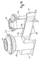
- a core element of the embodiment of the preheating structure according to the invention shown here is shown in Figures 1 and 2.
- Warm air nozzles are located in the passage holes 2 of a nozzle carrier plate 1 3 pushed through and put on shoulders 4.
- the bottom 5 of a distribution box 6 is placed from above so that the interior of the nozzle upper holes 7 in the bottom 5 with the interior of the distribution box 6 is connected. Via mounting screws shown in Figures 7 and 8 8, the distribution box 6 with the nozzles 3 is clamped to the nozzle carrier plate 1.
- the air inlet hole 10 is located approximately in the middle of the upper floor 9 of the distribution box 6 fixedly attached to the upper floor 9 and protruding from this feed pipe 11 from the outside a temperature sensor 12 which is connected to a controller via the plug 13.
- FIG. 1 shows, in addition to the one just described, at a short distance below the outlet opening 20 of the nozzle 3 arranged pack 21, here as a one-piece, open PET bottle is shown. It stands vertically on a conveyor, not shown, and has the bottle neck at the top 22 on, without touching a small but sufficient distance from the outlet opening 20 of the nozzle 3 is held.
- the packs 21 are produced in parallel longitudinal regions Representation of Figures 1 and 2 intermittently moved forward and against the viewing direction when stopping the bottle necks 22 under the outlet opening 20 of the nozzle 3 with warm air inside applied.
- Figure 3 shows an enlarged view of the upper, upstream end of the feed pipe 11 with the lower Connection flange 15 and above the upper connection flange 16 on the lower, downstream side End of the heating tube 19. Between the flanges 15 and 16, the swirl disk 18 is inserted and fixed sealingly on the sealing ring 23 on the outside.
- the swirl disk 18 is shown in three different views in FIGS. 4, 5 and 6. This clearly has a circular disc shape with a closed central area 24. Draw around it there are two partial circular rings, namely the inner partial circular ring 25 with the sector-shaped ring-shaped arrangement Openings 27 and the outer circular ring 26, which in turn is closed and over the radial webs 28 are connected to the closed central region 24. One also sees clearly the inclined blades 29, the angle of attack most clearly from the Side view of the swirl disk 18 according to FIG. 6 emerges.
- the swirl disk is preferably present 18 made of stainless steel, the blades 29 being connected to the radial webs 28 via the bending lines 30 are and are only angled downwards, so that the warm air flows from top to bottom is to think and only strokes through the openings 27.
- the preheating structure shown in somewhat more detail in FIGS. 7 and 8 with the pipelines has a flow meter 31 for the pressurized, low-germ preheating air, the flows in the direction of arrow 32 past the inlet valve 33 into the distributor pipe 34.
- the distributor pipe 34 runs essentially horizontally, while the heating tubes 19 extend vertically from the inlets 35 down to the flanges 15, 16 extend and open into the respective feed pipe 11 via the swirl disk 18.
- a heating rod 36 is attached, which leads through a current feedthrough is supplied with power in the lid 37.
- temperature sensor 38 connected to the heating element control.
- the heating pipes are further downstream 19 below connecting pieces 39 which connect the heating pipes 19 with a bypass pipe 40 (This is only shown in the embodiment of FIG. 7). Being one (left in Figure 7) End is designed as a connector and closed to the outside, while the other End of the bypass tube 40 (right in Figure 7) is provided with a blow-out opening 42 which a remote controlled valve 41 can be opened or closed. It was already up there mentions that in the event of a machine standstill if no preheating air is retrieved from the nozzles 3 is, the blow-out opening 42 is opened so that the main flow of the low-germ preheating air is removed through the bypass tube 40. This is sufficient in every company A lot of hot air is available, the flow meter 31 gives a signal to a not shown Control for the supply of a larger or smaller amount of low-germ warm air.
- the conveying direction of the packs 21 can be assumed in FIG. 8 against the viewing direction while in FIG. 7 the conveying direction is to be thought to the left and indicated by arrow 43 is.
- the circle shown in the middle at the bottom in FIG. 8 shows the front view of FIG Point of arrow 43.
- the distribution boxes 6 serve to better distribute and swirl the supplied warm air and have the task of making the difference in air flow velocities in each Reduce nozzles 3. While the diameter of the manifold at a preferred Example is 3 inches, the diameter of the heating tubes and the bypass tube is about 2 Inch. The temperature of the heating rods in normal operation is, for example, 110 ° C. It then succeeds in the temperature of the hot air emerging from the outlet opening 20 of the nozzle 3 Maintain 90 ° C to 100 ° C. The packs 21 are heated while the packs are at a standstill under the nozzles in a period of about 5 seconds.
- the warm air nozzle 3 shown enlarged in FIGS. 1 and 2, contains a nozzle tube 44, so that the nozzle 3 has the shape of an elongated tube.
- the nozzle tube 44 has in the on the upstream (upper) two thirds of its length a main duct 45 of larger diameter, which is followed downstream by an outlet channel 46 with a smaller diameter, to ultimately end in the outlet opening 20 below.
- the narrowed outlet or the outlet channel 46 with the smaller cross section provides for the warm air flowing vertically from top to bottom a throttle.
- This structure of the nozzle 3 also serves to distribute the warm air more evenly.
- the embodiment of the nozzle 3 according to FIGS. 1 and 2 is mainly used for the application the inner surface of a package 21 open at the top, in particular one on the neck 22 open PET bottle.
- the warm air nozzle 3 shown in FIGS. 9 and 10 it extends from the one not shown here Bottom of the junction box up to the top of the pack 21 in turn a nozzle tube 44a.
- a mounting flange 47 for mounting the Nozzle tube 44a attached to the nozzle support plate 1 and to the distribution box 6.
- the top opening 48 of the nozzle tube 44a again fits into the holes 7 in the base 5 of the distributor box 6, so that the warm air flows in from top to bottom.
- the main channel 45a is in the nozzle tube 44a relatively large and can not only the bottle neck 22 of the pack 21, but also the reach around at a distance from this molded dome 49.
Landscapes
- Engineering & Computer Science (AREA)
- Mechanical Engineering (AREA)
- Package Closures (AREA)
- Resistance Heating (AREA)
- Means For Warming Up And Starting Carburetors (AREA)
- Charge And Discharge Circuits For Batteries Or The Like (AREA)
- Pigments, Carbon Blacks, Or Wood Stains (AREA)
- Apparatus For Disinfection Or Sterilisation (AREA)
- Food Preservation Except Freezing, Refrigeration, And Drying (AREA)
Description
- Figur 1
- den Querschnitt wichtiger Teile des abgebrochen dargestellten Vorwärmaufbaus mit einem Verteilerkasten mit zwei in Querrichtung nebeneinander angeordneten Warmluftdüsen,
- Figur 2
- eine ähnliche Darstellung wie Figur 1, wobei jedoch zwei Packungen in Form von Kunststoffflaschen unter den Düsen angeordnet dargestellt sind,
- Figur 3
- abgebrochen, perspektivisch und vergrößert die Anordnung der Drallscheibe zwischen Zuführrohr und Heizrohr,
- Figur 4
- eine perspektivische Draufsicht auf die Drallscheibe,
- Figur 5
- eine Draufsicht auf die Drallscheibe in Fließrichtung der Warmluft,
- Figur 6
- eine Querschnittsansicht der Drallscheibe entlang der Linie A-A der Figur 5,
- Figur 7
- den Vorwärmaufbau mit fünf Verteilerkästen, die in Querrichtung nebeneinander angeordnet sind und jeweils vier Düsen aufweisen, einschließlich des etwa horizontal verlaufenden Verteilerrohres und des Bypaßrohres,
- Figur 8
- im Schnitt ein ähnlicher Aufbau wie Figur 7, jedoch ohne Bypaßrohr,
- Figur 9
- die Querschnittsansicht einer Warmluftdüse einer alternativen Ausführungsform mit Blasekanal und
- Figur 10
- perspektivisch und teilweise abgebrochen zwei Düsenrohre und den Blasekanal mit Blaslöchern.
- 1
- Düsenträgerplatte
- 2
- Durchtrittsloch
- 3
- Warmluftdüse
- 4
- Schulter
- 5
- Boden des Verteilerkastens
- 6
- Verteilerkasten
- 7
- Löcher im Boden des Verteilerkastens
- 8
- Befestigungsschraube
- 9
- Oberboden
- 10
- Lufteintrittsloch
- 11
- Zuführrohr
- 12
- Temperatursensor
- 13
- Stecker
- 15
- unterer Anschlußflansch
- 16
- oberer Anschlußflansch
- 17
- Klemmschraube
- 18
- Drallscheibe
- 19
- Heizrohr
- 20
- Auslaßöffnung
- 21
- Packung, Flasche
- 22
- Flaschenhals
- 23
- Dichtring
- 24
- Mittenbereich der Drallscheibe
- 25
- innerer Teilkreisring
- 26
- äußerer Teilkreisring
- 27
- sektorförmige Öffnung
- 28
- radialer Steg
- 29
- Schaufel
- 30
- Biegelinie
- 31
- Durchflußmesser
- 32
- Pfeil, Strömungsrichtung
- 33
- Einlaßventil
- 34
- Verteilerrohr
- 35
- Einlaß
- 36
- Heizstab
- 37
- Deckel
- 38
- oberer Temperatursensor
- 39
- Verbindungsstück
- 40
- Bypaßrohr
- 41
- ferngesteuertes Ventil
- 42
- Ausblasöffnung
- 43
- Pfeil, Förderrichtung der Packung
- 44, 44a
- Düsenrohr
- 45, 45a
- Hauptkanal
- 46
- Austrittskanal
- 47
- Befestigungsflansch
- 48
- obere Offnung
- 49
- Dom an der Flasche
- 50
- Blaslöcher
- 52
- weiteres Blasloch
- 53
- geschlossener Oberboden
- 54
- Seitenwand des Blaskanals
Claims (7)
- Vorwärmaufbau für einen Linearfüller, in welchem Packungen (21) in wenigstens zwei parallelen Längsreihen intermittierend unter verschiedene Bearbeitungsstationen zum Vorwärmen, Sterilisieren und Füllen bewegbar sind, wobei in dem Vorwärmaufbau Einrichtungen zur Erzeugung von erwärmter Druckluft, Rohrleitungen (19, 34, 40) und wenigstens zwei, mit den Rohrleitungen (19, 34, 40) verbundene Warmluftdüsen (3) derart vorgesehen sind, daß die Oberflächen der Packungen (21) mit Warmluft beaufschlagbar sind, dadurch gekennzeichnet, daß zur Verbesserung der Verwirbelung und Verteilung der Warmluft aufstromig vor den Düsen (3) ein mit wenigstens zwei Düsen verbundener Verteilerkasten (6) vorgesehen ist, in welchem ein Zuführrohr (11) mündet, dessen Strömungsquerschnitt von einer Drallscheibe (18) eingenommen ist.
- Vorwärmaufbau nach Anspruch 1, dadurch gekennzeichnet, daß wenigstens zwei Verteilerkästen (6) in der Vorwärmstation in einer Querrichtung nebeneinander angebracht sind, aufstromig vor jedem Zuführrohr (11) je ein Heizrohr (19) mit einem Heizstab (36) befestigt ist und in dem Zuführrohr (11) ein Temperatursensor (12) angebracht ist.
- Vorwärmaufbau nach Anspruch 1 oder 2, dadurch gekennzeichnet, daß an einer im wesentlichen horizontalen Düsenträgerplatte (1) vorzugsweise fünf Verteilerkästen (6) mit vorzugsweise je vier Düsen (3) in der Querreihe angeordnet sind und daß alle Heizrohre (19) mit einem Verteilerrohr (34) verbunden sind.
- Vorwärmaufbau nach einem der Ansprüche 1 bis 3, dadurch gekennzeichnet, daß die Drallscheibe (18) Kreisscheibenform hat mit einem geschlossenen Mittenbereich (24), um den schräg angestellte Schaufeln (29), die etwa sektorartige Öffnungen (27) teilweise verschließen, kranzartig angeordnet sind.
- Vorwärmaufbau nach einem der Ansprüche 1 bis 4, dadurch gekennzeichnet, daß die Heizrohre (19) mit einem Bypaßrohr (40) etwa gleichen Durchmessers verbunden sind, an dessen einem Ende eine verschließbare Ausblasöffnung (42) angebracht ist und dessen anderes Ende geschlossen ist.
- Vorwärmaufbau nach einem der Ansprüche 1 bis 5, dadurch gekennzeichnet, daß die Warmluftdüse (3) ein sich vom Boden (5) des Verteilerkastens (6) weg bis dicht über die Oberseite (22) der Packung (21) erstreckendes Düsenrohr (44) mit verengtem Austritt (46) aufweist.
- Vorwärmaufbau nach einem der Ansprüche 1 bis 5, dadurch gekennzeichnet, daß die Warmluftdüse (3) ein sich vom Boden (5) des Verteilerkastens (6) weg bis dicht über die Oberseite (22, 49) der Packung (21) erstreckendes Düsenrohr (44a) aufweist, dessen abstromiges Ende einen sich parallel zur Förderrichtung (43) der Packungen (21) parallel zu den Längsreihen der Packungen (21) erstreckenden, an beiden Enden und unten offenen Blasekanal (50) übergreift, dessen Seitenwände (54) innerhalb des Düsenrohres (44a) Blaslöcher (51, 52) aufweist.
Applications Claiming Priority (3)
| Application Number | Priority Date | Filing Date | Title |
|---|---|---|---|
| DE10045064 | 2000-09-12 | ||
| DE10045064A DE10045064A1 (de) | 2000-09-12 | 2000-09-12 | Vorwärmaufbau für einen Linearfüller |
| PCT/EP2001/009093 WO2002022490A1 (de) | 2000-09-12 | 2001-08-07 | Vorwärmaufbau für einen linearfüller |
Publications (2)
| Publication Number | Publication Date |
|---|---|
| EP1317394A1 EP1317394A1 (de) | 2003-06-11 |
| EP1317394B1 true EP1317394B1 (de) | 2004-03-24 |
Family
ID=7655919
Family Applications (1)
| Application Number | Title | Priority Date | Filing Date |
|---|---|---|---|
| EP01974123A Expired - Lifetime EP1317394B1 (de) | 2000-09-12 | 2001-08-07 | Vorwärmaufbau für einen linearfüller |
Country Status (7)
| Country | Link |
|---|---|
| EP (1) | EP1317394B1 (de) |
| AT (1) | ATE262480T1 (de) |
| AU (1) | AU2001293729A1 (de) |
| BR (1) | BR0113817A (de) |
| DE (2) | DE10045064A1 (de) |
| MX (1) | MXPA03002074A (de) |
| WO (1) | WO2002022490A1 (de) |
Families Citing this family (1)
| Publication number | Priority date | Publication date | Assignee | Title |
|---|---|---|---|---|
| DE102019131494B4 (de) | 2019-11-21 | 2023-10-05 | Khs Gmbh | Vorrichtung und Verfahren zum Behandeln von Behältern |
Family Cites Families (8)
| Publication number | Priority date | Publication date | Assignee | Title |
|---|---|---|---|---|
| DE2839543C2 (de) * | 1978-09-12 | 1986-06-05 | Siegfried Ing.(grad.) 8901 Königsbrunn Ammann | Verfahren und Vorrichtung zum Sterilisieren bzw. Entkeimen von Behältern, insbesondere Joghurtbechern |
| DE3540161A1 (de) * | 1985-11-13 | 1987-05-14 | Pkl Verpackungssysteme Gmbh | Verfahren und vorrichtung zum entkeimen von verpackungsmaterial, insbesondere von verpackungsbehaeltern |
| DE4031472C2 (de) * | 1990-10-05 | 2001-06-28 | Hoerauf Michael Maschf | Vorrichtung zum Sterilisieren, Füllen und Verschließen von eine Füllöffnung aufweisenden Behältern |
| GB9022268D0 (en) * | 1990-10-13 | 1990-11-28 | Cmb Foodcan Plc | Sterilising apparatus |
| DE4226616C2 (de) * | 1992-08-12 | 1994-09-29 | Karl Heess Gmbh & Co Kg | Vorrichtung zur Behandlung von Behältern vor dem Befüllen |
| DE19642987A1 (de) * | 1996-10-18 | 1998-04-23 | Tetra Laval Holdings & Finance | Verfahren und Vorrichtung zum Sterilisieren und Befüllen von Verpackungsbehältern |
| AU8767798A (en) * | 1997-08-15 | 1999-03-08 | Tetra Laval Holdings & Finance Sa | Method and apparatus for the sterilization of a carton |
| DE19945500C2 (de) * | 1998-09-22 | 2003-05-22 | Sig Combibloc Gmbh | Verfahren und Vorrichtung zum Entkeimen von Behältern in einer Füllmaschine |
-
2000
- 2000-09-12 DE DE10045064A patent/DE10045064A1/de not_active Withdrawn
-
2001
- 2001-08-07 WO PCT/EP2001/009093 patent/WO2002022490A1/de not_active Ceased
- 2001-08-07 BR BR0113817-0A patent/BR0113817A/pt not_active IP Right Cessation
- 2001-08-07 MX MXPA03002074A patent/MXPA03002074A/es unknown
- 2001-08-07 AT AT01974123T patent/ATE262480T1/de not_active IP Right Cessation
- 2001-08-07 AU AU2001293729A patent/AU2001293729A1/en not_active Abandoned
- 2001-08-07 DE DE50101797T patent/DE50101797D1/de not_active Expired - Lifetime
- 2001-08-07 EP EP01974123A patent/EP1317394B1/de not_active Expired - Lifetime
Also Published As
| Publication number | Publication date |
|---|---|
| WO2002022490A1 (de) | 2002-03-21 |
| AU2001293729A1 (en) | 2002-03-26 |
| BR0113817A (pt) | 2003-07-08 |
| EP1317394A1 (de) | 2003-06-11 |
| DE10045064A1 (de) | 2002-03-28 |
| DE50101797D1 (de) | 2004-04-29 |
| MXPA03002074A (es) | 2003-10-06 |
| ATE262480T1 (de) | 2004-04-15 |
Similar Documents
| Publication | Publication Date | Title |
|---|---|---|
| EP0932577B1 (de) | Verfahren und vorrichtung zum sterilisieren und befüllen von verpackungsbehältern | |
| EP1311304B1 (de) | Vorrichtung zum sterilisieren von packungen mit wasserstoffperoxid | |
| EP2388126B2 (de) | Blasmaschine mit Zuleitungssterilisation | |
| EP2173388B1 (de) | Verdampfer zum sterilisieren von kunststoffbehältern | |
| EP2431058B1 (de) | Aseptik-Sterilisationseinheit für Reinraum | |
| EP2421662B1 (de) | Vorrichtung und verfahren zum aseptischen abfüllen oder abpacken von inhaltsstoffen in behälter | |
| EP2595790B1 (de) | Verfahren und vorrichtung zum sterilisieren von vorformlingen | |
| DE69915257T2 (de) | Einheit zum Sterilisieren eines Materialstreifens in einer Verpackungsmaschine für das Verpacken von fliessfähigen Nahrungsmitteln, und Verpackungsmaschine mit einer solchen Einheit | |
| EP2746029B1 (de) | Vorrichtung und Verfahren zum Sterilisieren von Behältnissen | |
| EP2655040B1 (de) | Verfahren und vorrichtung zur blasformung von sterilen behältern | |
| EP3052387B1 (de) | Vorrichtung zur veränderung der strahlform von fliessfähigen produkten | |
| EP2554483B1 (de) | Schrumpftunnel | |
| DE102021003226A1 (de) | Vorrichtung | |
| DE102013104152A1 (de) | Vorrichtung und Verfahren zur Außensterilisation von Kunststoffvorformlingen | |
| DE10323335A1 (de) | Herstellvorrichtung | |
| DE69915594T2 (de) | Einheit zum Sterilisieren einer Materialbahn in einer Verpackungsmaschine für das Verpacken von fließfähigen Nahrungsmitteln, und Verpackungsmaschine mit einer solchen Einheit | |
| EP2008667B1 (de) | Vorrichtung zum Behandeln von Gefäßen in einem Gefäßdesinfektionssystem | |
| EP3546382B1 (de) | Dampfbalken und schrumpftunnel | |
| DE4037254C2 (de) | ||
| EP1317394A1 (de) | Vorwärmaufbau für einen linearfüller | |
| DE102016123137A1 (de) | Verfahren und Füllmaschine zum Füllen von einseitig offenen Packungen | |
| DE1936577A1 (de) | Vorrichtung zum Einfuellen von kleinteiligen,aufschaeumbaren,thermoplastischen Kunststoffen in Formen mit Hilfe von Druckluft | |
| EP4650144A1 (de) | Verfahren und vorrichtung zur kontaminationsfreien behandlung von behältern in einer behandlungsmaschine | |
| WO2026041253A1 (de) | System | |
| DE102024001610A1 (de) | Vorrichtung und Verfahren |
Legal Events
| Date | Code | Title | Description |
|---|---|---|---|
| PUAI | Public reference made under article 153(3) epc to a published international application that has entered the european phase |
Free format text: ORIGINAL CODE: 0009012 |
|
| 17P | Request for examination filed |
Effective date: 20030205 |
|
| AK | Designated contracting states |
Designated state(s): AT BE CH CY DE DK ES FI FR GB GR IE IT LI LU MC NL PT SE TR |
|
| AX | Request for extension of the european patent |
Extension state: AL LT LV MK RO SI |
|
| GRAP | Despatch of communication of intention to grant a patent |
Free format text: ORIGINAL CODE: EPIDOSNIGR1 |
|
| GRAS | Grant fee paid |
Free format text: ORIGINAL CODE: EPIDOSNIGR3 |
|
| GRAA | (expected) grant |
Free format text: ORIGINAL CODE: 0009210 |
|
| AK | Designated contracting states |
Kind code of ref document: B1 Designated state(s): AT BE CH CY DE DK ES FI FR GB GR IE IT LI LU MC NL PT SE TR |
|
| PG25 | Lapsed in a contracting state [announced via postgrant information from national office to epo] |
Ref country code: IE Free format text: LAPSE BECAUSE OF FAILURE TO SUBMIT A TRANSLATION OF THE DESCRIPTION OR TO PAY THE FEE WITHIN THE PRESCRIBED TIME-LIMIT Effective date: 20040324 Ref country code: NL Free format text: LAPSE BECAUSE OF FAILURE TO SUBMIT A TRANSLATION OF THE DESCRIPTION OR TO PAY THE FEE WITHIN THE PRESCRIBED TIME-LIMIT Effective date: 20040324 Ref country code: FI Free format text: LAPSE BECAUSE OF FAILURE TO SUBMIT A TRANSLATION OF THE DESCRIPTION OR TO PAY THE FEE WITHIN THE PRESCRIBED TIME-LIMIT Effective date: 20040324 Ref country code: CY Free format text: LAPSE BECAUSE OF FAILURE TO SUBMIT A TRANSLATION OF THE DESCRIPTION OR TO PAY THE FEE WITHIN THE PRESCRIBED TIME-LIMIT Effective date: 20040324 Ref country code: TR Free format text: LAPSE BECAUSE OF FAILURE TO SUBMIT A TRANSLATION OF THE DESCRIPTION OR TO PAY THE FEE WITHIN THE PRESCRIBED TIME-LIMIT Effective date: 20040324 |
|
| REG | Reference to a national code |
Ref country code: GB Ref legal event code: FG4D Free format text: NOT ENGLISH |
|
| REG | Reference to a national code |
Ref country code: CH Ref legal event code: EP |
|
| REG | Reference to a national code |
Ref country code: IE Ref legal event code: FG4D Free format text: GERMAN |
|
| REF | Corresponds to: |
Ref document number: 50101797 Country of ref document: DE Date of ref document: 20040429 Kind code of ref document: P |
|
| PG25 | Lapsed in a contracting state [announced via postgrant information from national office to epo] |
Ref country code: DK Free format text: LAPSE BECAUSE OF FAILURE TO SUBMIT A TRANSLATION OF THE DESCRIPTION OR TO PAY THE FEE WITHIN THE PRESCRIBED TIME-LIMIT Effective date: 20040624 Ref country code: GR Free format text: LAPSE BECAUSE OF FAILURE TO SUBMIT A TRANSLATION OF THE DESCRIPTION OR TO PAY THE FEE WITHIN THE PRESCRIBED TIME-LIMIT Effective date: 20040624 Ref country code: SE Free format text: LAPSE BECAUSE OF FAILURE TO SUBMIT A TRANSLATION OF THE DESCRIPTION OR TO PAY THE FEE WITHIN THE PRESCRIBED TIME-LIMIT Effective date: 20040624 |
|
| PG25 | Lapsed in a contracting state [announced via postgrant information from national office to epo] |
Ref country code: ES Free format text: LAPSE BECAUSE OF FAILURE TO SUBMIT A TRANSLATION OF THE DESCRIPTION OR TO PAY THE FEE WITHIN THE PRESCRIBED TIME-LIMIT Effective date: 20040705 |
|
| GBT | Gb: translation of ep patent filed (gb section 77(6)(a)/1977) |
Effective date: 20040621 |
|
| PG25 | Lapsed in a contracting state [announced via postgrant information from national office to epo] |
Ref country code: AT Free format text: LAPSE BECAUSE OF NON-PAYMENT OF DUE FEES Effective date: 20040807 Ref country code: LU Free format text: LAPSE BECAUSE OF NON-PAYMENT OF DUE FEES Effective date: 20040807 |
|
| PG25 | Lapsed in a contracting state [announced via postgrant information from national office to epo] |
Ref country code: BE Free format text: LAPSE BECAUSE OF NON-PAYMENT OF DUE FEES Effective date: 20040831 Ref country code: MC Free format text: LAPSE BECAUSE OF NON-PAYMENT OF DUE FEES Effective date: 20040831 |
|
| NLV1 | Nl: lapsed or annulled due to failure to fulfill the requirements of art. 29p and 29m of the patents act | ||
| LTIE | Lt: invalidation of european patent or patent extension |
Effective date: 20040324 |
|
| REG | Reference to a national code |
Ref country code: IE Ref legal event code: FD4D |
|
| ET | Fr: translation filed | ||
| PLBE | No opposition filed within time limit |
Free format text: ORIGINAL CODE: 0009261 |
|
| STAA | Information on the status of an ep patent application or granted ep patent |
Free format text: STATUS: NO OPPOSITION FILED WITHIN TIME LIMIT |
|
| BERE | Be: lapsed |
Owner name: S.A. *TETRA LAVAL HOLDINGS & FINANCE Effective date: 20040831 |
|
| 26N | No opposition filed |
Effective date: 20041228 |
|
| PG25 | Lapsed in a contracting state [announced via postgrant information from national office to epo] |
Ref country code: CH Free format text: LAPSE BECAUSE OF NON-PAYMENT OF DUE FEES Effective date: 20050831 Ref country code: LI Free format text: LAPSE BECAUSE OF NON-PAYMENT OF DUE FEES Effective date: 20050831 |
|
| REG | Reference to a national code |
Ref country code: CH Ref legal event code: PL |
|
| BERE | Be: lapsed |
Owner name: S.A. *TETRA LAVAL HOLDINGS & FINANCE Effective date: 20040831 |
|
| PG25 | Lapsed in a contracting state [announced via postgrant information from national office to epo] |
Ref country code: PT Free format text: LAPSE BECAUSE OF NON-PAYMENT OF DUE FEES Effective date: 20040824 |
|
| REG | Reference to a national code |
Ref country code: FR Ref legal event code: PLFP Year of fee payment: 15 |
|
| PGFP | Annual fee paid to national office [announced via postgrant information from national office to epo] |
Ref country code: DE Payment date: 20150722 Year of fee payment: 15 Ref country code: GB Payment date: 20150724 Year of fee payment: 15 |
|
| PGFP | Annual fee paid to national office [announced via postgrant information from national office to epo] |
Ref country code: FR Payment date: 20150727 Year of fee payment: 15 |
|
| PGFP | Annual fee paid to national office [announced via postgrant information from national office to epo] |
Ref country code: IT Payment date: 20150728 Year of fee payment: 15 |
|
| REG | Reference to a national code |
Ref country code: DE Ref legal event code: R119 Ref document number: 50101797 Country of ref document: DE |
|
| GBPC | Gb: european patent ceased through non-payment of renewal fee |
Effective date: 20160807 |
|
| REG | Reference to a national code |
Ref country code: FR Ref legal event code: ST Effective date: 20170428 |
|
| PG25 | Lapsed in a contracting state [announced via postgrant information from national office to epo] |
Ref country code: DE Free format text: LAPSE BECAUSE OF NON-PAYMENT OF DUE FEES Effective date: 20170301 Ref country code: GB Free format text: LAPSE BECAUSE OF NON-PAYMENT OF DUE FEES Effective date: 20160807 Ref country code: FR Free format text: LAPSE BECAUSE OF NON-PAYMENT OF DUE FEES Effective date: 20160831 |
|
| PG25 | Lapsed in a contracting state [announced via postgrant information from national office to epo] |
Ref country code: IT Free format text: LAPSE BECAUSE OF NON-PAYMENT OF DUE FEES Effective date: 20160807 |