EP1317077A2 - DS-CDMA transmission method - Google Patents
DS-CDMA transmission method Download PDFInfo
- Publication number
- EP1317077A2 EP1317077A2 EP03075508A EP03075508A EP1317077A2 EP 1317077 A2 EP1317077 A2 EP 1317077A2 EP 03075508 A EP03075508 A EP 03075508A EP 03075508 A EP03075508 A EP 03075508A EP 1317077 A2 EP1317077 A2 EP 1317077A2
- Authority
- EP
- European Patent Office
- Prior art keywords
- code
- pilot symbols
- code channels
- block
- channel
- Prior art date
- Legal status (The legal status is an assumption and is not a legal conclusion. Google has not performed a legal analysis and makes no representation as to the accuracy of the status listed.)
- Granted
Links
Images


Classifications
-
- H—ELECTRICITY
- H04—ELECTRIC COMMUNICATION TECHNIQUE
- H04J—MULTIPLEX COMMUNICATION
- H04J13/00—Code division multiplex systems
- H04J13/16—Code allocation
- H04J13/18—Allocation of orthogonal codes
-
- H—ELECTRICITY
- H04—ELECTRIC COMMUNICATION TECHNIQUE
- H04J—MULTIPLEX COMMUNICATION
- H04J13/00—Code division multiplex systems
-
- H—ELECTRICITY
- H04—ELECTRIC COMMUNICATION TECHNIQUE
- H04B—TRANSMISSION
- H04B7/00—Radio transmission systems, i.e. using radiation field
- H04B7/24—Radio transmission systems, i.e. using radiation field for communication between two or more posts
- H04B7/26—Radio transmission systems, i.e. using radiation field for communication between two or more posts at least one of which is mobile
- H04B7/2628—Radio transmission systems, i.e. using radiation field for communication between two or more posts at least one of which is mobile using code-division multiple access [CDMA] or spread spectrum multiple access [SSMA]
- H04B7/2637—Radio transmission systems, i.e. using radiation field for communication between two or more posts at least one of which is mobile using code-division multiple access [CDMA] or spread spectrum multiple access [SSMA] for logical channel control
-
- H—ELECTRICITY
- H04—ELECTRIC COMMUNICATION TECHNIQUE
- H04B—TRANSMISSION
- H04B2201/00—Indexing scheme relating to details of transmission systems not covered by a single group of H04B3/00 - H04B13/00
- H04B2201/69—Orthogonal indexing scheme relating to spread spectrum techniques in general
- H04B2201/707—Orthogonal indexing scheme relating to spread spectrum techniques in general relating to direct sequence modulation
- H04B2201/70701—Orthogonal indexing scheme relating to spread spectrum techniques in general relating to direct sequence modulation featuring pilot assisted reception
-
- H—ELECTRICITY
- H04—ELECTRIC COMMUNICATION TECHNIQUE
- H04J—MULTIPLEX COMMUNICATION
- H04J13/00—Code division multiplex systems
- H04J13/0077—Multicode, e.g. multiple codes assigned to one user
Definitions
- the present invention relates to a direct sequence code division multiple access (DS-CDMA) transmission method carrying out multiple access using spread spectrum in mobile communications, and particularly to a DS-CDMA transmission method that carries out code multiplexing of multiple code channels.
- DS-CDMA direct sequence code division multiple access
- the DS-CDMA transmission system carries out communications between multiple users using the same frequency band, and individual users are identified by a spreading code properly assigned to each user.
- the DS-CDMA system has advantages over the frequency division multiple access or time division multiple access in that it can increase the capacity in terms of the number of simultaneous subscribers within the same available frequency band, and is suitable for high speed signal transmission because it transmits information signals after spreading them into wideband signals.
- the received signal undergoes Rayleigh fading.
- Rayleigh fading the amplitude of a received signal has Rayleigh distribution, and its phase has a uniform distribution. It is necessary for a receiver to estimate the randomly varying phase of the received signal to carry out coherent detection which is more efficient than differential detection.
- One of the methods for estimating the received phase is implemented by inserting pilot symbols of a known pattern into information symbols at fixed intervals, and by estimating the received phase of each information symbol on the basis of the received phases estimated using the pilot symbols. In this case, the pilot symbols must be inserted at every time interval during which the phase fluctuation due to fading is nearly negligible.
- Fig. 16 shows a conventional channel structure when carrying out the absolute coherent detection which makes the channel (amplitude and phase) estimation using the pilot symbols as mentioned above.
- N denotes the number of code channels (the number of code multiplexing).
- Each code channel is spread using a short code (SC-1, ..., SC-N) with a period equal to that of information symbol, and is further spread using a spreading code referred to as a long code (LC-Y) with a period much longer than that of the common information symbol.
- the short codes serve to identify the individual code channels
- the long code serves to distinguish a user from the other simultaneous users in the same cell in reverse link channels, and from the other simultaneous users in the other cells in forward link channels.
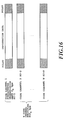
- Fig. 17 shows a frame structure of a single code channel transmission.
- the conventional system has the following problems:
- Another object of the present invention is to provide a DS-CDMA transmission method which can improve the tracking ability to fading of the channel estimation and the transmission power control using the pilot symbols without much increasing the circuit scale of the transmitter and receiver in the DS-CDMA code multiplexing.
- a DS-CDMA transmission method using a code multiplexing method which transmits a signal by generating a high bit rate transmission channel by code multiplexing a plurality of code channels comprises the steps of:
- a DS-CDMA transmission method using a code multiplexing method which transmits a signal by generating a high bit rate transmission channel by code multiplexing a plurality of code channels comprises the steps of:
- a DS-CDMA transmission method using a code multiplexing method which transmits a signal by generating a high bit rate transmission channel by code multiplexing a plurality of code channels comprises the steps of:
- a DS-CDMA transmission method using a code multiplexing method which transmits a signal by generating a high bit rate transmission channel by code multiplexing a plurality of code channels comprises, when assembling frames for respective code channels by inserting into information symbols pilot symbols used for channel estimation for coherent detection at fixed intervals, the steps of:
- the DS-CDMA transmission method may further comprise, when carrying out the channel estimation for the coherent detection using the pilot symbols, the steps of:
- the DS-CDMA transmission method may further comprise, when measuring received signal power for carrying out transmission power control, the steps of:
- Fig. 1 is a diagram illustrating an example of a channel structure in the DS-CDMA transmission system in accordance with the present invention
- Fig. 2 is a diagram illustrating another example of a channel structure in the DS-CDMA transmission system in accordance with the present invention
- Fig. 3 is a block diagram showing a configuration of an embodiment of an error correcting encoder in the DS-CDMA transmission system in accordance with the present invention
- Fig. 4 is a block diagram showing another configuration of an embodiment of an error correcting encoder in the DS-CDMA transmission system in accordance with the present invention
- Fig. 5 is a block diagram showing a configuration of an embodiment of a transmitter in the DS-CDMA transmission system in accordance with the present invention
- Fig. 6 is a block diagram showing a configuration of an embodiment of a receiver in the DS-CDMA transmission system in accordance with the present invention.
- Fig. 7 is a block diagram showing a configuration of an embodiment of an error correcting decoder in the DS-CDMA transmission system in accordance with the present invention.
- Fig. 8 is a block diagram showing another configuration of an embodiment of an error correcting decoder in the DS-CDMA transmission system in accordance with the present invention.
- Fig. 9A is a diagram illustrating the operation of an interleaver in the DS-CDMA transmission system in accordance with the present invention.
- Fig. 9B is a diagram illustrating the operation of a deinterleaver in the DS-CDMA transmission system in accordance with the present invention.
- Fig. 10A is a diagram illustrating the operation of an interleaver in the DS-CDMA transmission system in accordance with the present invention
- Fig. 10B is a diagram illustrating the operation of a deinterleaver in the DS-CDMA transmission system in accordance with the present invention.
- Fig. 11 is a diagram illustrating another example of a channel structure in the DS-CDMA transmission system in accordance with the present invention.
- Fig. 12 illustrates the relationship between Fig. 12A and 12B.
- Fig. 14 illustrates the relationship between Fig. 14A and 14B.
- Fig. 14A is a block diagram showing another configuration of the embodiment of the transmitter in the DS-CDMA transmission system in accordance with the present invention.
- Fig. 14B is a block diagram showing another configuration of the embodiment of the transmitter in the DS-CDMA transmission system in accordance with the present invention.
- Fig. 15 illustrates the relationship between Fig. 15A and 15B.
- Fig. 15A is a block diagram showing another configuration of the embodiment of the receiver in the DS-CDMA transmission system in accordance with the present invention.
- Fig. 15B is a block diagram showing another configuration of the embodiment of the receiver in the DS-CDMA transmission system in accordance with the present invention.
- Fig. 16 is a diagram illustrating a conventional code multiplexing method
- Fig. 17 is a diagram illustrating a frame structure of a single code channel transmission
- Fig. 18A is a diagram illustrating a conventional pilot symbol insertion pattern
- Fig. 18B is a diagram illustrating a conventional channel estimation method
- Fig. 19 is a diagram illustrating conventional transmission power control timings.
- Fig. 20 is a flowchart showing a transmission and reception method in accordance with the present invention.
- Fig. 1 shows an example of a channel structure of a DS-CDMA transmission system in accordance with the present invention.
- each frame of a code channel with a fundamental transmission rate fb consists of pilot symbols and information data whose information rate is expanded by spreading factor (processing gain) into a wideband signal.
- the N code multiplexing of such fundamental channels enables the information to be transmitted at the transmission rate of N ⁇ fb bps, if all the channels have the same quality as the fundamental channel.
- a common spreading code is used to spread the pilot symbols of the N code channels, the cross-correlation between the individual code channels can be eliminated. Since the code channels undergo the same fading in the multicode multiplex transmission, the same pilot symbols can be used in common.
- Fig. 2 illustrates a channel structure different from that of Fig. 1, in which only one code channel transmits the pilot symbols.
- Fig. 3 is a block diagram showing an error correcting encoder in the multicode multiplex transmission.
- Input information data is coded by an outer code encoder 1 using an outer code of a concatenated error correcting code, undergoes interleaving by an interleaver 2, and is distributed to N code channels through a serial-to-parallel converter 3.
- convolutional coding by a convolutional encoder 4 and interleaving by an interleaver 5 are carried out successively for each code channel.
- Fig. 9A illustrates an interleaving method of the DS-CDMA transmission system.
- the entire information data in Z-frames are written in the X 1 data direction for each code channel, and are read in the Y 1 data direction perpendicular to the write direction.
- Fig. 4 shows a configuration of an error correcting encoder of the transmitter of the DS-CDMA transmission system.
- the input information data is encoded by an outer code encoder 6 using an outer code of a concatenated error correcting code, and undergoes interleaving by an interleaver 7 to be output.
- the output data collectively undergo a convolutional coding by a convolutional encoder 8, and the convolutionally encoded information sequence is collectively interleaved by an interleaver 9.
- Fig. 10A illustrates an interleaving method of the present DS-CDMA transmission system.
- the convolutionally encoded information data sequence is written at every N ⁇ X 2 period, and after thus writing the entire information data in the Z frames, the data are read at every Y2 information data period in the direction perpendicular to the write direction.
- the interleaved information data are distributed into N code channels by a serial-to-parallel converter 10.
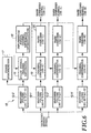
- Fig. 5 is a block diagram showing the transmitter of the DS-CDMA transmission system.
- Each frame assembler 11 inserts pilot symbols, which are used for channel estimation for the coherent detection, into the coded information data of each code channel shown in Figs. 3 and 4 at fixed intervals (the pilot symbols may be inserted into only one code channel if it is desired to do so).
- the data are modulated by each modulator 12.
- the modulated data symbols of each code channel output from each modulator 12 are spread using a spreading code (SC-X ⁇ LC-Y) for the pilot symbols, and using spreading codes (SC-P ⁇ LC-Y, where P represents 1-N) for the information symbols of respective code channels.
- the spread signals of respective code channels are summed up by an adder 14 to be transmitted.
- Fig. 6 is a block diagram showing a receiver of the DS-CDMA transmission system.
- the received spread signal is input in common to matched filters 15-0, ..., 15-N corresponding to the spreading codes.
- the pilot symbols in the received signal are despread by the matched filter 15-0 using the spreading code (SC-X ⁇ LC-Y) as the spreading code replica.
- the received phase of the pilot symbols is estimated by a pilot symbol channel estimator 16 which averages several pilot symbols using the output from a frame synchronizer 17.
- An information symbol channel estimator 18 estimates the received phase at each position of the information symbols by interpolating the estimated information fed from the pilot symbol channel estimator 16.
- the estimated phase fluctuations in the information symbols can be used in common to the entire code channels.
- the information symbols on individual code channels are despread by the matched filters 15-1 - 15-N using different spreading codes (SC-P ⁇ LC-Y, where P denotes 1-N) as spreading code replicas for respective channels.
- SC-P ⁇ LC-Y different spreading codes
- each channel compensator 19 compensates the despread information symbols on the code channels for the received phase fluctuations which are estimated using the pilot symbols.
- the phase estimator and compensator (17, 18 and 19) which use pilot channels corresponding to N code channels as shown in Fig. 6, are used for each multipath to be combined.
- the information symbols from respective paths which have been compensated for the fading phase fluctuations by the channel compensator 19 of each channel are RAKE combined by a RAKE combiner 20 which sums up the-multipath components using estimated received complex envelopes of individual paths as weights.
- the RAKE combined signals are each input to an error correcting decoder as shown in Figs. 7 and 8.
- Fig. 7 shows a configuration of the error correcting decoder of the DS-CDMA transmission system.
- the RAKE combined signals are each deinterleaved by a deinterleaver 21 separately for each code channel.
- Fig. 9B illustrates a deinterleaving method of the DS-CDMA transmission system, in which write and read are carried out in the directions opposite to those in the interleaving method as shown in Fig. 9A.
- the deinterleaved signals are each decoded by a Viterbi decoder 22 separately for each channel.
- the decoded data of the respective code channels undergo parallel-to-serial conversion by a parallel-to-serial converter 23, followed by the deinterleave by a deinterleaver 24 and the decoding by an outer code decoder 25, to be output.
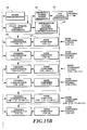
- Fig. 8 shows another configuration of the error correcting decoder of the DS-CDMA transmission system.
- the RAKE combined signals of the N code channels undergo parallel-to-serial conversion by a parallel-to-serial converter 26, and then are collectively deinterleaved by a deinterleaver 27.
- Fig. 10B illustrates a deinterleaving method of the DS-CDMA transmission system, in which write and read are carried out in the directions opposite to those in the interleaving method as shown in Fig. 10A.
- the deinterleaved signals are collectively decoded by a Viterbi decoder 28, followed by the deinterleave by a deinterleaver 29 and decoding by an outer code decoder 30, to be output.
- Fig. 11 shows another example of a channel structure of a DS-CDMA transmission system in accordance with the present invention.
- each frame of a code channel with a fundamental transmission rate fb consists of pilot symbols and information data whose information rate is expanded by the spreading factor (processing gain), thereby generating a wideband signal.
- the N code multiplexing of such fundamental channels enables the information to be transmitted at the transmission rate of N ⁇ fb bps, if all the channels have the same quality as the fundamental channel.
- the integer K may be even or odd.
- the H code channels in the same block have the pilot symbols inserted at the same positions in the frames. With regard to the entire pilot symbols in the different K blocks of the code channels, the inserted positions of the pilot symbols in the K blocks are shifted such that the intervals become uniform between the closest pilot symbols.
- the input information data also undergo the error correcting encoding by the error correcting encoder as shown in Fig. 3.
- the data are interleaved by the same method as shown in Fig. 9A.
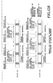
- Fig. 14A and Fig. 14B are block diagrams showing the transmitter of the DS-CDMA transmission system
- Fig. 20 is a flowchart of the transmission and reception (S200-S250).
- Each frame assembler 31 inserts pilot symbols, which are used for channel estimation for the coherent detection, into the coded information data of each code channel fed from the circuit as shown in Fig. 3, at fixed intervals in accordance with a pilot symbol insertion pattern of the block to which the code channel belongs (S200-S210).
- the modulated data symbols of the code channels output from respective modulators 32 are separately spread by spreading modulators 33 using spreading codes (SC-P ⁇ LC-Y, where P represents 1-N) assigned to respective code channels (S215).
- the spread signals of the respective code channels are summed up by an adder 34 to be transmitted (S220).
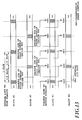
- Fig. 15A and Fig. 15B are block diagrams showing a receiver of the DS-CDMA transmission system.
- the received spread signal is input in common to matched filters 35 corresponding to the respective spreading codes.
- the pilot symbols and information symbols in the code channels are despread separately for respective channels by the matched filters 35 using the spreading codes (SC-P ⁇ LC-Y, where P represents 1-N) as the spreading code replicas (S225).
- a demultiplexer (DEMUX) 36 corresponding to each code channel extracts from the information symbols the pilot symbols inserted into different positions in the respective blocks (S230).
- the received phase of the pilot symbols is estimated by a pilot symbol channel estimator 37 which averages separately for each code channel between several pilot symbols using the output from a frame synchronizer 38 which carries out coherent detection of the pilot symbols in response to the output of the matched filter 35 (S235).
- the estimates of the received phase at the pilot symbol positions in each block are obtained by averaging the estimates of the received phase of the code channels in that block (S240).
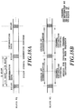
- Fig. 12A shows a pilot symbol insertion pattern in each block.
- An information symbol channel estimator 39 can obtain transfer functions of the channels on the information data sequence by making interpolation at every insertion interval of the entire pilot symbols throughout the entire code channels by using, in common to all the code channels, the estimates of the received phase at the pilot symbol positions of the respective blocks as shown in Fig. 12B (S245). This can improve the tracking ability to fading in the channel estimation because of the reduced interval of the interpolation in the channel estimation.
- each channel compensator 40 compensates the information symbols on the code channels fed from the demultiplexers 36 for the received phase fluctuations which are estimated using the pilot symbols (S250).
- a received signal power measurer 41 measures the received signal power at the pilot symbol positions of each code channel on the basis of the signal fed from the pilot symbol channel estimator 37. Then, it averages in each block the measured values of the received signal power of the code channels belonging to that block, thereby obtaining the measured values of the received signal power (SIR) at the pilot symbol positions of the block.
- a transmission power control signal generator 42 generates a transmission power control (TPC) signal based on the measured values.
- TPC transmission power control
- the measured values of the received signal power at the pilot symbol positions in respective blocks are used in common to the entire code channels as shown in Fig. 13. This makes it possible to achieve the transmission power control at the insertion intervals of the entire pilot symbols inserted into all the code channels, and hence to improve the fading tracking ability in the transmission power control because of the virtually reduced transmission power control period.
- the phase estimator and compensator (37, 38, 39 and 40), which use pilot channels corresponding to N code channels as shown in Fig. 15, are used for each multipath to be combined.
- the information symbols from respective paths which have been compensated for the fading phase fluctuations by each channel compensator 40 are RAKE combined by each RAKE combiner 43 which sums up the multipath components using estimated received complex envelopes of individual paths as weights.
- the RAKE combined signals are each input to an error correcting decoder as shown in Fig. 7. Its operation and the deinterleave method (Fig. 9B) are the same as those of the embodiment 1.
Landscapes
- Engineering & Computer Science (AREA)
- Computer Networks & Wireless Communication (AREA)
- Signal Processing (AREA)
- Mobile Radio Communication Systems (AREA)
Abstract

Description
- The present invention relates to a direct sequence code division multiple access (DS-CDMA) transmission method carrying out multiple access using spread spectrum in mobile communications, and particularly to a DS-CDMA transmission method that carries out code multiplexing of multiple code channels.
- Recently, intensive research and development of the DS-CDMA system have been made as one of the next generation mobile communication systems. The DS-CDMA transmission system carries out communications between multiple users using the same frequency band, and individual users are identified by a spreading code properly assigned to each user.
- The DS-CDMA system has advantages over the frequency division multiple access or time division multiple access in that it can increase the capacity in terms of the number of simultaneous subscribers within the same available frequency band, and is suitable for high speed signal transmission because it transmits information signals after spreading them into wideband signals.
- In the mobile communication environment, straight paths between a base station and mobile stations are seldom unobstructed, thereby constituting multipath propagation. As a result, the received signal undergoes Rayleigh fading. In Rayleigh fading, the amplitude of a received signal has Rayleigh distribution, and its phase has a uniform distribution. It is necessary for a receiver to estimate the randomly varying phase of the received signal to carry out coherent detection which is more efficient than differential detection. One of the methods for estimating the received phase is implemented by inserting pilot symbols of a known pattern into information symbols at fixed intervals, and by estimating the received phase of each information symbol on the basis of the received phases estimated using the pilot symbols. In this case, the pilot symbols must be inserted at every time interval during which the phase fluctuation due to fading is nearly negligible.
- There are mainly two methods for implementing high bit rate signal transmission in the DS-CDMA system: (1) a method which varies a spreading factor (processing gain) in accordance with the transmission information rate; and (2) a code multiplexing method which multiplexes multiple channels each having a fundamental information rate. Here, we will consider the second method.
- Fig. 16 shows a conventional channel structure when carrying out the absolute coherent detection which makes the channel (amplitude and phase) estimation using the pilot symbols as mentioned above. In this figure, N denotes the number of code channels (the number of code multiplexing). Each code channel is spread using a short code (SC-1, ..., SC-N) with a period equal to that of information symbol, and is further spread using a spreading code referred to as a long code (LC-Y) with a period much longer than that of the common information symbol. The short codes serve to identify the individual code channels, and the long code serves to distinguish a user from the other simultaneous users in the same cell in reverse link channels, and from the other simultaneous users in the other cells in forward link channels. Fig. 17 shows a frame structure of a single code channel transmission.
- The conventional system has the following problems:
- (1) The pilot symbols, which are inserted into
each code channel as
shown in Fig. 16, are spread by the same spreading code assigned to each code channel for spreading data symbols. This results in some cross-correlation between the multiplexed code channels, which degrades the accuracy of the channel estimation by the pilot symbols. In other words, the conventional DS-CDMA code multiplexing method has a problem in that the accuracy of the channel estimation using the pilot symbols degrades owing to the cross-correlation between other code channels because the pilot symbols of respective code channels are spread using different spreading codes. The degradation is remarkable when the received signal power per path decreases under the multipath environment. - (2) The pilot symbols, which are inserted at the same positions in frames in the respective code channels as shown in Fig. 18A, are used to estimate the received phases for each code channel so as to obtain the transfer function of the channel on information data sequence by means of interpolation at the insertion intervals of the pilot symbols as shown in Fig. 18B. This results in a problem in that the accuracy of the channel estimation degrades with an increase in the fading fluctuation speed. In addition, since the transmission power control is also carried out at the insertion intervals of the pilot symbols by measuring the received signal power at the positions of the pilot symbols which are inserted in the same positions in the frames of respective code channels as shown in Fig. 19, there is another problem in that the accuracy of the transmission power control also degrades with an increase in the fading fluctuation speed.
-
- It is therefore an object of the present invention to provide a DS-CDMA transmission method which can improve the accuracy of the channel estimation without much increasing the circuit scale of a transmitter and receiver in the DS-CDMA code multiplexing.
- Another object of the present invention is to provide a DS-CDMA transmission method which can improve the tracking ability to fading of the channel estimation and the transmission power control using the pilot symbols without much increasing the circuit scale of the transmitter and receiver in the DS-CDMA code multiplexing.
- According to a first aspect of the present invention, a DS-CDMA transmission method using a code multiplexing method which transmits a signal by generating a high bit rate transmission channel by code multiplexing a plurality of code channels, the DS-CDMA transmission method comprises the steps of:
- assembling frames for respective code channels by inserting pilot symbols into information symbols at fixed intervals, the pilot symbols being used for channel estimation for coherent detection;
- spreading the information symbols in each of the code channels using a spreading code properly assigned to the each of the code channels, the spreading code being selected from a group of orthogonal spreading codes that are orthogonal to each other and have a period equal to an information symbol period; and
- spreading the pilot symbols in the code channels using one of the spreading codes being selected from the group of the orthogonal spreading codes, or any of the spreading codes other than the spreading codes assigned to the information symbols in the code channels from the group of the orthogonal spreading codes.
-
- According to a second aspect of the present invention, a DS-CDMA transmission method using a code multiplexing method which transmits a signal by generating a high bit rate transmission channel by code multiplexing a plurality of code channels, the DS-CDMA transmission method comprises the steps of:
- assembling frames for one of the code channels by inserting pilot symbols into information symbols at fixed intervals, the pilot symbols being used for channel estimation for coherent detection;
- spreading the information symbols in each of the code channels using a spreading code properly assigned to the each of the code channels, the spreading code being selected from a group of orthogonal spreading codes that are orthogonal to each other and have a period equal to an information symbol period; and
- spreading the pilot symbols, which are generated only in the one of the code channels, using one of the spreading codes being selected from the group of the orthogonal spreading codes, or any of the spreading codes other than the spreading codes assigned to the information symbols in the code channels from the group of the orthogonal spreading codes.
-
- According to a third aspect of the present invention, a DS-CDMA transmission method using a code multiplexing method which transmits a signal by generating a high bit rate transmission channel by code multiplexing a plurality of code channels, the DS-CDMA transmission method comprises the steps of:
- convolutionally encoding transmitted data collectively;
- writing a convolutionally encoded information data sequence collectively at every N × X2 interval, where N is a number of code channels;
- reading, after having written entire information data in Z frames in a direction, where Z is a natural number, the information data in a direction perpendicular to the direction in which the entire information data in Z frames are written at every Y2 interval, where X2 and Y2 are natural numbers that satisfy the relations N × X2 ≅ Y2, and N × X2 × Y2 = the total number of information data in the Z frames; and
- carrying out interleaving that distributes the read information data to N code channels after interleaving.
-
- According to a fourth aspect of the present invention, a DS-CDMA transmission method using a code multiplexing method which transmits a signal by generating a high bit rate transmission channel by code multiplexing a plurality of code channels, the DS-CDMA transmission method comprises, when assembling frames for respective code channels by inserting into information symbols pilot symbols used for channel estimation for coherent detection at fixed intervals, the steps of:
- dividing N code channels to K blocks each consisting of H code channels, where N is a number of multiplexed code channels, K is a number of blocks, H is a number of code channels in the block, and N = H × K;
- inserting pilot symbols into same positions of frames in the H code channels in a same block; and
- shifting positions of inserting the pilot symbols from block to block such that intervals between closest pilot symbols become uniform with regard to entire pilot symbols in the K blocks.
-
- Here, the DS-CDMA transmission method may further comprise, when carrying out the channel estimation for the coherent detection using the pilot symbols, the steps of:
- obtaining channel estimates at the positions of the pilot symbols in the code channels using the pilot symbols inserted into the information symbols according to a pilot symbol insertion pattern in the block to which the code channel belongs;
- obtaining channel estimates at the positions of the pilot symbols in each of the blocks by averaging the channel estimates of H code channels in that block; and
- obtaining transfer functions of the code channels on an information data sequence at pilot symbol insertion intervals of the entire pilot symbols inserted to the entire code channels, the transfer functions being obtained by interpolation using, in common to the entire code channels, the channel estimates at the positions of the pilot symbols in the blocks.
-
- Here, the DS-CDMA transmission method may further comprise, when measuring received signal power for carrying out transmission power control, the steps of:
- measuring the received signal power of the code channels using the pilot symbols inserted into the information symbols according to a pilot symbol insertion pattern in the block to which the code channel belongs;
- obtaining measured values of the received signal power at the positions of the pilot symbols in each of the blocks by averaging the measured received signal power of the H code channels in that block; and
- carrying out the transmission power control at pilot symbol insertion intervals of the entire pilot symbols distributed to the entire code channels using, in common to the entire code channels, the measured values of the received signal power at the positions of the pilot symbols in the blocks.
-
- The above and other objects, effects, features and advantages of the present invention will become more apparent from the following description of the embodiments thereof taken in conjunction with the accompanying drawings.
- Fig. 1 is a diagram illustrating an example of a channel structure in the DS-CDMA transmission system in accordance with the present invention;
- Fig. 2 is a diagram illustrating another example of a channel structure in the DS-CDMA transmission system in accordance with the present invention;
- Fig. 3 is a block diagram showing a configuration of an embodiment of an error correcting encoder in the DS-CDMA transmission system in accordance with the present invention;
- Fig. 4 is a block diagram showing another configuration of an embodiment of an error correcting encoder in the DS-CDMA transmission system in accordance with the present invention;
- Fig. 5 is a block diagram showing a configuration of an embodiment of a transmitter in the DS-CDMA transmission system in accordance with the present invention;
- Fig. 6 is a block diagram showing a configuration of an embodiment of a receiver in the DS-CDMA transmission system in accordance with the present invention;
- Fig. 7 is a block diagram showing a configuration of an embodiment of an error correcting decoder in the DS-CDMA transmission system in accordance with the present invention;
- Fig. 8 is a block diagram showing another configuration of an embodiment of an error correcting decoder in the DS-CDMA transmission system in accordance with the present invention;
- Fig. 9A is a diagram illustrating the operation of an interleaver in the DS-CDMA transmission system in accordance with the present invention;
- Fig. 9B is a diagram illustrating the operation of a deinterleaver in the DS-CDMA transmission system in accordance with the present invention;
- Fig. 10A is a diagram illustrating the operation of an interleaver in the DS-CDMA transmission system in accordance with the present invention;
- Fig. 10B is a diagram illustrating the operation of a deinterleaver in the DS-CDMA transmission system in accordance with the present invention;
- Fig. 11 is a diagram illustrating another example of a channel structure in the DS-CDMA transmission system in accordance with the present invention;
- Fig. 12 illustrates the relationship between Fig. 12A and 12B.
- Fig. 12A is a diagram illustrating a pilot symbol insertion pattern (when a block number K = 2) in the DS-CDMA transmission system in accordance with the present invention;
- Fig. 12B is a diagram illustrating a channel estimation method (when a block number K = 2) in the DS-CDMA transmission system in accordance with the present invention;
- Fig. 13 is a diagram illustrating transmission power control timings (when a block number K = 2) in the DS-CDMA transmission system in accordance with the present invention;
- Fig. 14 illustrates the relationship between Fig. 14A and 14B.
- Fig. 14A is a block diagram showing another configuration of the embodiment of the transmitter in the DS-CDMA transmission system in accordance with the present invention;
- Fig. 14B is a block diagram showing another configuration of the embodiment of the transmitter in the DS-CDMA transmission system in accordance with the present invention;
- Fig. 15 illustrates the relationship between Fig. 15A and 15B.
- Fig. 15A is a block diagram showing another configuration of the embodiment of the receiver in the DS-CDMA transmission system in accordance with the present invention;
- Fig. 15B is a block diagram showing another configuration of the embodiment of the receiver in the DS-CDMA transmission system in accordance with the present invention;
- Fig. 16 is a diagram illustrating a conventional code multiplexing method;
- Fig. 17 is a diagram illustrating a frame structure of a single code channel transmission;
- Fig. 18A is a diagram illustrating a conventional pilot symbol insertion pattern;
- Fig. 18B is a diagram illustrating a conventional channel estimation method;
- Fig. 19 is a diagram illustrating conventional transmission power control timings; and
- Fig. 20 is a flowchart showing a transmission and reception method in accordance with the present invention.
- The invention will now be described with reference to the accompanying drawings.
- Fig. 1 shows an example of a channel structure of a DS-CDMA transmission system in accordance with the present invention. As shown in Fig. 1, each frame of a code channel with a fundamental transmission rate fb consists of pilot symbols and information data whose information rate is expanded by spreading factor (processing gain) into a wideband signal. The N code multiplexing of such fundamental channels enables the information to be transmitted at the transmission rate of N × fb bps, if all the channels have the same quality as the fundamental channel. In this case, if a common spreading code is used to spread the pilot symbols of the N code channels, the cross-correlation between the individual code channels can be eliminated. Since the code channels undergo the same fading in the multicode multiplex transmission, the same pilot symbols can be used in common. Fig. 2 illustrates a channel structure different from that of Fig. 1, in which only one code channel transmits the pilot symbols.
- Fig. 3 is a block diagram showing an error correcting encoder in the multicode multiplex transmission. Input information data is coded by an
outer code encoder 1 using an outer code of a concatenated error correcting code, undergoes interleaving by aninterleaver 2, and is distributed to N code channels through a serial-to-parallel converter 3. Subsequently, convolutional coding by aconvolutional encoder 4 and interleaving by aninterleaver 5 are carried out successively for each code channel. Fig. 9A illustrates an interleaving method of the DS-CDMA transmission system. The entire information data in Z-frames are written in the X1 data direction for each code channel, and are read in the Y1 data direction perpendicular to the write direction. Here, X1 and Y1 are natural numbers satisfying the relations N × X1 × Y1 = the total number of information data in the Z frames, and X1 ≅ Y1. - Fig. 4 shows a configuration of an error correcting encoder of the transmitter of the DS-CDMA transmission system. As in Fig. 3, the input information data is encoded by an
outer code encoder 6 using an outer code of a concatenated error correcting code, and undergoes interleaving by aninterleaver 7 to be output. The output data collectively undergo a convolutional coding by aconvolutional encoder 8, and the convolutionally encoded information sequence is collectively interleaved by aninterleaver 9. Fig. 10A illustrates an interleaving method of the present DS-CDMA transmission system. The convolutionally encoded information data sequence is written at every N × X2 period, and after thus writing the entire information data in the Z frames, the data are read at every Y2 information data period in the direction perpendicular to the write direction. Here, X2 and Y2 are natural numbers satisfying the relations N × X2 × Y2 = the total number of the information data in the Z frames, and N × X2 ≅ Y2. - After that, the interleaved information data are distributed into N code channels by a serial-to-
parallel converter 10. - Fig. 5 is a block diagram showing the transmitter of the DS-CDMA transmission system. Each
frame assembler 11 inserts pilot symbols, which are used for channel estimation for the coherent detection, into the coded information data of each code channel shown in Figs. 3 and 4 at fixed intervals (the pilot symbols may be inserted into only one code channel if it is desired to do so). Subsequently, the data are modulated by eachmodulator 12. The modulated data symbols of each code channel output from each modulator 12 are spread using a spreading code (SC-X⊗LC-Y) for the pilot symbols, and using spreading codes (SC-P⊗LC-Y, where P represents 1-N) for the information symbols of respective code channels. The spread signals of respective code channels are summed up by anadder 14 to be transmitted. - Fig. 6 is a block diagram showing a receiver of the DS-CDMA transmission system. The received spread signal is input in common to matched filters 15-0, ..., 15-N corresponding to the spreading codes. The pilot symbols in the received signal are despread by the matched filter 15-0 using the spreading code (SC-X⊗LC-Y) as the spreading code replica. Then, the received phase of the pilot symbols is estimated by a pilot
symbol channel estimator 16 which averages several pilot symbols using the output from aframe synchronizer 17. An informationsymbol channel estimator 18 estimates the received phase at each position of the information symbols by interpolating the estimated information fed from the pilotsymbol channel estimator 16. Since the code channels in the received signal undergo the same fluctuations due to fading, the estimated phase fluctuations in the information symbols can be used in common to the entire code channels. On the other hand, the information symbols on individual code channels are despread by the matched filters 15-1 - 15-N using different spreading codes (SC-P⊗LC-Y, where P denotes 1-N) as spreading code replicas for respective channels. Using the signal fed from the informationsymbol channel estimator 18, eachchannel compensator 19 compensates the despread information symbols on the code channels for the received phase fluctuations which are estimated using the pilot symbols. In a multipath configuration, the phase estimator and compensator (17, 18 and 19), which use pilot channels corresponding to N code channels as shown in Fig. 6, are used for each multipath to be combined. The information symbols from respective paths which have been compensated for the fading phase fluctuations by thechannel compensator 19 of each channel are RAKE combined by aRAKE combiner 20 which sums up the-multipath components using estimated received complex envelopes of individual paths as weights. - The RAKE combined signals are each input to an error correcting decoder as shown in Figs. 7 and 8.
- Fig. 7 shows a configuration of the error correcting decoder of the DS-CDMA transmission system. The RAKE combined signals are each deinterleaved by a
deinterleaver 21 separately for each code channel. Fig. 9B illustrates a deinterleaving method of the DS-CDMA transmission system, in which write and read are carried out in the directions opposite to those in the interleaving method as shown in Fig. 9A. The deinterleaved signals are each decoded by aViterbi decoder 22 separately for each channel. The decoded data of the respective code channels undergo parallel-to-serial conversion by a parallel-to-serial converter 23, followed by the deinterleave by adeinterleaver 24 and the decoding by anouter code decoder 25, to be output. - Fig. 8 shows another configuration of the error correcting decoder of the DS-CDMA transmission system. The RAKE combined signals of the N code channels undergo parallel-to-serial conversion by a parallel-to-
serial converter 26, and then are collectively deinterleaved by adeinterleaver 27. Fig. 10B illustrates a deinterleaving method of the DS-CDMA transmission system, in which write and read are carried out in the directions opposite to those in the interleaving method as shown in Fig. 10A. The deinterleaved signals are collectively decoded by aViterbi decoder 28, followed by the deinterleave by adeinterleaver 29 and decoding by anouter code decoder 30, to be output. - Fig. 11 shows another example of a channel structure of a DS-CDMA transmission system in accordance with the present invention. As shown in Fig. 11, each frame of a code channel with a fundamental transmission rate fb consists of pilot symbols and information data whose information rate is expanded by the spreading factor (processing gain), thereby generating a wideband signal. The N code multiplexing of such fundamental channels enables the information to be transmitted at the transmission rate of N × fb bps, if all the channels have the same quality as the fundamental channel. Here, the N code channels are divided into K blocks each consisting of H code channels, where N is the number of multiplexed code channels, K is the number of blocks, H is the number of code channels in each block, and N = H × K. The integer K may be even or odd. The H code channels in the same block have the pilot symbols inserted at the same positions in the frames. With regard to the entire pilot symbols in the different K blocks of the code channels, the inserted positions of the pilot symbols in the K blocks are shifted such that the intervals become uniform between the closest pilot symbols.
- In the present embodiment, the input information data also undergo the error correcting encoding by the error correcting encoder as shown in Fig. 3. In addition, the data are interleaved by the same method as shown in Fig. 9A.
- Fig. 14A and Fig. 14B are block diagrams showing the transmitter of the DS-CDMA transmission system, and Fig. 20 is a flowchart of the transmission and reception (S200-S250). Each
frame assembler 31 inserts pilot symbols, which are used for channel estimation for the coherent detection, into the coded information data of each code channel fed from the circuit as shown in Fig. 3, at fixed intervals in accordance with a pilot symbol insertion pattern of the block to which the code channel belongs (S200-S210). The modulated data symbols of the code channels output fromrespective modulators 32 are separately spread by spreadingmodulators 33 using spreading codes (SC-P⊗LC-Y, where P represents 1-N) assigned to respective code channels (S215). The spread signals of the respective code channels are summed up by anadder 34 to be transmitted (S220). - Fig. 15A and Fig. 15B are block diagrams showing a receiver of the DS-CDMA transmission system. The received spread signal is input in common to matched
filters 35 corresponding to the respective spreading codes. The pilot symbols and information symbols in the code channels are despread separately for respective channels by the matched filters 35 using the spreading codes (SC-P⊗LC-Y, where P represents 1-N) as the spreading code replicas (S225). A demultiplexer (DEMUX) 36 corresponding to each code channel extracts from the information symbols the pilot symbols inserted into different positions in the respective blocks (S230). Then, the received phase of the pilot symbols is estimated by a pilotsymbol channel estimator 37 which averages separately for each code channel between several pilot symbols using the output from aframe synchronizer 38 which carries out coherent detection of the pilot symbols in response to the output of the matched filter 35 (S235). The estimates of the received phase at the pilot symbol positions in each block are obtained by averaging the estimates of the received phase of the code channels in that block (S240). Fig. 12A shows a pilot symbol insertion pattern in each block. An informationsymbol channel estimator 39 can obtain transfer functions of the channels on the information data sequence by making interpolation at every insertion interval of the entire pilot symbols throughout the entire code channels by using, in common to all the code channels, the estimates of the received phase at the pilot symbol positions of the respective blocks as shown in Fig. 12B (S245). This can improve the tracking ability to fading in the channel estimation because of the reduced interval of the interpolation in the channel estimation. Using the signal fed from the informationsymbol channel estimator 39, eachchannel compensator 40 compensates the information symbols on the code channels fed from thedemultiplexers 36 for the received phase fluctuations which are estimated using the pilot symbols (S250). - In terms of transmission power control, a received
signal power measurer 41 measures the received signal power at the pilot symbol positions of each code channel on the basis of the signal fed from the pilotsymbol channel estimator 37. Then, it averages in each block the measured values of the received signal power of the code channels belonging to that block, thereby obtaining the measured values of the received signal power (SIR) at the pilot symbol positions of the block. A transmission powercontrol signal generator 42 generates a transmission power control (TPC) signal based on the measured values. The measured values of the received signal power at the pilot symbol positions in respective blocks are used in common to the entire code channels as shown in Fig. 13. This makes it possible to achieve the transmission power control at the insertion intervals of the entire pilot symbols inserted into all the code channels, and hence to improve the fading tracking ability in the transmission power control because of the virtually reduced transmission power control period. - In a multipath configuration, the phase estimator and compensator (37, 38, 39 and 40), which use pilot channels corresponding to N code channels as shown in Fig. 15, are used for each multipath to be combined. The information symbols from respective paths which have been compensated for the fading phase fluctuations by each
channel compensator 40 are RAKE combined by eachRAKE combiner 43 which sums up the multipath components using estimated received complex envelopes of individual paths as weights. The RAKE combined signals are each input to an error correcting decoder as shown in Fig. 7. Its operation and the deinterleave method (Fig. 9B) are the same as those of theembodiment 1. - The description also includes the following numbered clauses.
- 1. A DS-CDMA transmission method using a code
multiplexing method which transmits a signal by
generating a high bit rate transmission channel by
code multiplexing a plurality of code channels, said
DS-CDMA transmission method characterized by
comprising the steps of:
- assembling frames for respective code channels by inserting pilot symbols into information symbols at fixed intervals, said pilot symbols being used for channel estimation for coherent detection;
- spreading said information symbols in each of said code channels using a spreading code properly assigned to said each of said code channels, said spreading code being selected from a group of orthogonal spreading codes that are orthogonal to each other and have a period equal to an information symbol period; and
- spreading said pilot symbols in said code channels using one of the spreading codes being selected from said group of said orthogonal spreading codes, or any of the spreading codes other than the spreading codes assigned to said information symbols in said code channels from said group of said orthogonal spreading codes.
- 2. A DS-CDMA transmission method using a code
multiplexing method which transmits a signal by
generating a high bit rate transmission channel by
code multiplexing a plurality of code channels, said
DS-CDMA transmission method characterized by
comprising the steps of:
- assembling frames for one of said code channels by inserting pilot symbols into information symbols at fixed intervals, said pilot symbols being used for channel estimation for coherent detection;
- spreading said information symbols in each of said code channels using a spreading code properly assigned to said each of said code channels, said spreading code being selected from a group of orthogonal spreading codes that are orthogonal to each other and have a period equal to an information symbol period; and
- spreading said pilot symbols, which are generated only in said one of said code channels, using one of the spreading codes being selected from said group of said orthogonal spreading codes, or any of the spreading codes other than the spreading codes assigned to said information symbols in said code channels from said group of said orthogonal spreading codes.
- 3. A DS-CDMA transmission method using a code
multiplexing method which transmits a signal by
generating a high bit rate transmission channel by
code multiplexing a plurality of code channels, said
DS-CDMA transmission method characterized by
comprising the steps of:
- convolutionally encoding transmitted data collectively;
- writing a convolutionally encoded information data sequence collectively at every N × X2 interval, where N is a number of code channels;
- reading, after having written entire information data in Z frames in a direction, where Z is a natural number, said information data in a direction perpendicular to the direction in which said entire information data in Z frames are written at every Y2 interval, where X2 and Y2 are natural numbers that satisfy the relations N × X2 ≅ Y2, and N × X2 × Y2 = the total number of information data in said Z frames; and
- carrying out interleaving that distributes the read information data to N code channels after interleaving.
- 4. A DS-CDMA transmission method using a code
multiplexing method which transmits a signal by
generating a high bit rate transmission channel by
code multiplexing a plurality of code channels, said
DS-CDMA transmission method characterized by
comprising, when assembling frames for respective
code channels by inserting into information symbols
pilot symbols used for channel estimation for
coherent detection at fixed intervals, the steps of:
- dividing N code channels to K blocks each consisting of H code channels, where N is a number of multiplexed code channels, K is a number of blocks, H is a number of code channels in the block, and N = H × K;
- inserting pilot symbols into same positions of frames in the H code channels in a same block; and
- shifting positions of inserting said pilot symbols from block to block such that intervals between closest pilot symbols become uniform with regard to entire pilot symbols in the K blocks.
- 5. The DS-CDMA transmission method according to
clause 4, further characterized by comprising, when carrying out the channel estimation for the coherent detection using said pilot symbols, the steps of: - obtaining channel estimates at the positions of said pilot symbols in said code channels using said pilot symbols inserted into said information symbols according to a pilot symbol insertion pattern in the block to which said code channel belongs;
- obtaining channel estimates at the positions of said pilot symbols in each of said blocks by averaging said channel estimates of H code channels in that block; and
- obtaining transfer functions of said code channels on an information data sequence at pilot symbol insertion intervals of the entire pilot symbols inserted to the entire code channels, said transfer functions being obtained by interpolation using, in common to the entire code channels, said channel estimates at the positions of said pilot symbols in said blocks.
- 6. The DS-CDMA transmission method according to
clause 4, further characterized by comprising, when measuring received signal power for carrying out transmission power control, the steps of: - measuring said received signal power of said code channels using said pilot symbols inserted into said information symbols according to a pilot symbol insertion pattern in the block to which said code channel belongs;
- obtaining measured values of said received signal power at the positions of said pilot symbols in each of said blocks by averaging the measured received signal power of said H code channels in that block; and
- carrying out said transmission power control at pilot symbol insertion intervals of the entire pilot symbols distributed to the entire code channels using, in common to the entire code channels, said measured values of said received signal power at the positions of said pilot symbols in said blocks.
- 7. A DS-CDMA transmitter, for performing the method of
clause 1, having: - frame assembler means (11) for each code channel (CH-1,..CH-N) to frame information symbols and to insert, between information symbols at fixed intervals, pilot symbols patterned for coherent detection;
- spread modulation means (12,13) for each code channel, responsive to supplied spreading codes and operable on the frame information symbols and pilot symbols of each channel; and
- spreading code supply means to supply the spreading codes; wherein said spreading code supply means is adapted to supply a respective different orthogonal spreading code (SC-P ⊗ LC-Y:P=1 to N) for spreading the information symbols of each respective different channel and to supply a common spreading code (SC-X ⊗ LC-Y), that is either the same as one of said different orthogonal spreading codes or is orthogonal to said different orthogonal spreading codes, for spreading the pilot symbols of each channel, which spreading codes each have a period equal to that of said information symbols of each channel.
- 8. A DS-CDMA reception method for responding to the DS-CDMA
transmission method of
clause 1 comprising steps of: - despreading the spread information symbols in a received spread signal using replicas of the respective different orthogonal spreading codes (SC-1 ⊗ lc-y TO sc-n ⊗ LC-Y) for each code channel;
- despreading the spread pilot symbols using a replica of the common spreading code (SC-X ⊗ LC-Y);
- averaging a number of the despread pilot symbols to estimate the received phase thereof;
- estimating the received phase at each position of the information symbols by interpolating the estimated received phase of the pilot symbols; and
- compensating the despread information symbols in each code channel for received phase fluctuations using the estimates obtained for each position thereof.
- 9. A DS-CDMA receiver, for performing the method of
clause 8, having: - matched filter means (15-A to 15-N), operable on a received spread signal, for despreading the spread information symbols thereof on the basis of replicas of the different orthogonal spreading codes (SC-1 ⊗ LC-Y to SC-N ⊗ LC-Y);
- matched filter means (15-0) operable on the received spread signal, for despreading the spread pilot symbols thereof on the basis of a replica of the common spreading code;
- pilot symbol channel estimator means (16), responsive to frame synchronisation signals, operable on the despread pilot symbols, to average a number thereof and obtain an estimate of the received phase thereof;
- information symbol channel estimator means (18), to interpolate said estimate of the received phase of the pilot symbols to estimate the received phase at each position of the information symbols; and
- channel compensator means (19), responsive to the latter estimates, and operable on the despread information symbols in each code channel, to compensate them for received phase fluctuation.
- 10. The operable combination of the transmitter of
clause 7 and the receiver ofclause 9. - 11. A DS-CDMA transmitted signal in which the information symbols of respective different code channels have different spread encoding corresponding to the application of different orthogonal spreading codes, and the pilot symbols of the different code channels have a common spread encoding corresponding to the application of a spreading code that is the same as one of, or that is orthogonal to each of, said different orthogonal spreading codes.
- 12. A DS-CDMA transmitter, for performing the method of
clause 2, having: - frame assembler means (11) for each code channel to frame information symbols, a single one of said frame assembler means being operable to insert, between information symbols of one of the code channels, at fixed intervals, pilot symbols patterned for coherent detection;
- spread modulation means (12,13) for each code channel, responsive to supplied spreading codes, and operable on the frame information symbols of each channel, a single one of said spread modulation means for said one of said code channels, being responsive to a supplied spreading code, and operable on the pilot symbols of that one channel; and
- spreading code supply means to supply the spreading codes, which codes for each of the respective code channels are orthogonal to each other and the spreading code for said one channel, applicable to the pilot symbols, is the same as any one of, or is orthogonal to, said orthogonal codes and all said spreading codes each have a period equal to that of said information symbols of each channel.
- 13. A DS-CDMA reception method to correspond to the DS-CDMA
transmission method of
clause 2, comprising steps of: - despreading the spread information symbols in a received spread signal using replicas of the respective different orthogonal spreading codes (SC-1 ⊗ LC-Y to SC-N ⊗ LC-Y) for each code channel;
- despreading the spread pilot symbols of the one code channel using a replica of the spreading coding for said one channel that is applicable as aforesaid to the pilot symbols;
- averaging a number of the despread pilot symbols to estimate the received phase thereof;
- estimating the received phase at each position of the information symbols by interpolating the estimated received phase of the pilot symbols; and
- compensating the despread information symbols in each code channel for received phase fluctuations using the estimates obtained for each position thereof.
- 14. A DS-CDMA receiver, for performing the method of
clause 13, having - matched filter means (15-A to 15-N), operable on a received spread signal, for despreading the spread information symbols thereof on the basis of replicas of the different orthogonal spreading codes;
- matched filter means, operable on the received spread signal, for despreading the spread pilot symbols of the specified one code channel thereof on the basis of a replica of the specified one spreading code therefor;
- pilot symbol channel estimator means (16), responsive to frame synchronisation signals, operable on the despread pilot symbols, to average a number thereof and obtain an estimate of the received phase thereof;
- information symbol channel estimator means (18), to interpolate said estimate of the received phase of the pilot symbols to estimate the received phase at each position of the information symbols; and
- channel compensator means (19), responsive to the latter estimates, and operable on the despread information symbols in each code channel, to compensate them for received phase fluctuation.
- 15. The operative combination of the transmitter of
clause 12 and the receiver ofclause 14. - 16. A DS-CDMA transmitted signal in which the information symbols of respective different code channels have different spread encoding corresponding to the application of different orthogonal spreading codes, and the pilot symbols, provided only in a single one of the code channels, have a spread encoding corresponding to the application of a spreading code that is the same as one of, or that is orthogonal to each of, said different orthogonal spreading codes.
- 17. An error correction encoder for performing the
method of clause 3 comprising:
- convolutional encoder means (7) for encoding information data;
- interleaver means (9) for writing a convolutionally encoded information data sequence collectively at every N ×X2 interval, where N is a number of code channels, and for reading, after having written entire information data in Z frames in a direction, where Z is a natural number, said information data in a direction perpendicular to the direction in which said entire information data in Z frames are written at every Y2 interval, where X2 and Y2 are natural numbers that satisfy the relations N × X2 ≅ Y2, and N x X2 × Y2 = the total number of information data in said Z frames; and
- serial-to-parallel converter means (10) to distribute the interleaved information data from said interleaver means to N code channels.
- 18. The error correction encoder of
clause 17 arranged preceding and combined with the transmitter ofclause 7 or, alternatively, the transmitter ofclause 12. - 19. An error correction decoder for decoding information
data encoded by the method of clause 3, comprising:
- parallel to serial converter means (26) operable on information data in each of a plurality of code channels;
- deinterleaver means (27) for writing the serial information data of Z frames every Y2 interval and for reading the written information every N x X2 interval; and
- decoder means (28) operable to decode the convoluted deinterleaved information data read from said deinterleaver means.
- 20. The error correction decoder of
clause 19 arranged following and combined with the receiver ofclause 9 or, alternatively, the receiver ofclause 14. - 21. A DS-CDMA transmitter for performing the method of
clause 4, comprising: - a plurality N of frame assembler means (31) each to receive information data of a respective one of N coded channels, arranged in K blocks of H in number thereof, each to frame information data symbols and to insert pilot symbols between information data symbols at a respective position the same in the H code channels in the same block and shifted in position relative to each of the remainder blocks such that the intervals between closest pilot symbols are uniform.
-
Claims (5)
- A DS-CDMA transmission method using a code multiplexing method which transmits a signal generated by code multiplexing through a plurality of code channels, said DS-CDMA transmission method comprising, when assembling frames for respective code channels by adding to information symbols pilot symbols used for channel estimation for coherent detection at fixed intervals, the steps of:dividing N code channels between K blocks each consisting of H code channels, where N is the number of multiplexed code channels, K is the number of blocks, H is the number of code channels in the block, and N=HxK;adding pilot symbols at the same frame position in the H code channels in the same block; andshifting positions at which said pilot symbols are added from block to block such that the intervals between the closest pilot symbols become uniform with regard to the entire pilot symbols in the K blocks.
- The DS-CDMA transmission method as claimed in claim 1, wherein channel estimates are obtained for each code channel by using said pilot symbols, the channel estimates in the same block are averaged to obtain channel estimates at pilot symbol positions in each block, and channel estimates at positions other than the pilot symbol positions in each block are obtained by interpolating the channel estimates at the pilot symbol positions in each block.
- The DS-CDMA transmission method as claimed in claim 1, wherein the received signal power is measured for each code channel by using said pilot symbols, the measured values of the received signal power in the same block are averaged to obtain received signal power values at pilot symbol positions in each block, and in each code channel, transmission power control is carried out at the pilot symbol positions in each block by using the received signal power values at the pilot symbol positions in each block.
- A DS-CDMA transmission apparatus using a code multiplexing method which transmits a signal generated by code multiplexing through the N code channels, where N≥Z, said DS-CDMA transmission apparatus comprising:an encoder (1) for coding input data;a distributor (3, 10) for distributing the coded input data to K blocks each consisting of H code channels, where 1≤H<N and K=N/H;frame assemblers (31) for placing pilot symbols at the same frame position in the code channels in each block and placing pilot symbols at different frame positions between code channels of different blocks, said pilot symbols being used for channel estimation for coherent detection; andspreading modulators (33) for spreading the signals in which said pilot symbols have been added to information symbols by said frame assemblers (31) using a different spreading code for each code channel.
- An interleaving method in a communication system which interleaves a transmission data sequence whose length is Z, and divides the interleaved transmission data sequence into N, where N≥Z, encoded information data and transmits the N encoded information data, the method comprising the steps of:writing said transmission data sequence, into an interleaver which has two dimensional matrix structure and in which the matrix has NxX2 rows and Z/(NxX2) columns, in the column direction of the matrix at every NxX2 period, X2 being an integer; andreading, after having written said transmission data sequence, said transmission data sequence from the interleaver in the row direction of the matrix at every Z/(NxX2) period.
Applications Claiming Priority (5)
| Application Number | Priority Date | Filing Date | Title |
|---|---|---|---|
| JP13661596 | 1996-05-30 | ||
| JP13661596 | 1996-05-30 | ||
| JP8214496A JPH1051354A (en) | 1996-05-30 | 1996-08-14 | Ds-cdma transmission method |
| JP21449696 | 1996-08-14 | ||
| EP97303705A EP0810742B1 (en) | 1996-05-30 | 1997-05-30 | Direct sequence code division multiple access transmission method using pilot symbols |
Related Parent Applications (1)
| Application Number | Title | Priority Date | Filing Date |
|---|---|---|---|
| EP97303705A Division EP0810742B1 (en) | 1996-05-30 | 1997-05-30 | Direct sequence code division multiple access transmission method using pilot symbols |
Publications (3)
| Publication Number | Publication Date |
|---|---|
| EP1317077A2 true EP1317077A2 (en) | 2003-06-04 |
| EP1317077A3 EP1317077A3 (en) | 2004-02-18 |
| EP1317077B1 EP1317077B1 (en) | 2005-11-09 |
Family
ID=26470136
Family Applications (2)
| Application Number | Title | Priority Date | Filing Date |
|---|---|---|---|
| EP03075508A Expired - Lifetime EP1317077B1 (en) | 1996-05-30 | 1997-05-30 | DS-CDMA transmission method |
| EP97303705A Revoked EP0810742B1 (en) | 1996-05-30 | 1997-05-30 | Direct sequence code division multiple access transmission method using pilot symbols |
Family Applications After (1)
| Application Number | Title | Priority Date | Filing Date |
|---|---|---|---|
| EP97303705A Revoked EP0810742B1 (en) | 1996-05-30 | 1997-05-30 | Direct sequence code division multiple access transmission method using pilot symbols |
Country Status (7)
| Country | Link |
|---|---|
| US (2) | US6097711A (en) |
| EP (2) | EP1317077B1 (en) |
| JP (1) | JPH1051354A (en) |
| KR (1) | KR100271121B1 (en) |
| CN (3) | CN1163011C (en) |
| CA (1) | CA2206380C (en) |
| DE (2) | DE69729605T2 (en) |
Families Citing this family (94)
| Publication number | Priority date | Publication date | Assignee | Title |
|---|---|---|---|---|
| JP2863993B2 (en) * | 1995-06-22 | 1999-03-03 | 松下電器産業株式会社 | CDMA wireless multiplex transmitting apparatus, CDMA wireless multiplex transmitting apparatus, CDMA wireless receiving apparatus, and CDMA wireless multiplex transmitting method |
| CA2286816C (en) * | 1997-04-17 | 2004-02-17 | Ntt Mobile Communications Network Inc. | Base station apparatus of mobile communication system |
| US5991330A (en) * | 1997-06-27 | 1999-11-23 | Telefonaktiebolaget L M Ericsson (Pub1) | Mobile Station synchronization within a spread spectrum communication systems |
| US6396822B1 (en) * | 1997-07-15 | 2002-05-28 | Hughes Electronics Corporation | Method and apparatus for encoding data for transmission in a communication system |
| JP3159378B2 (en) * | 1997-08-13 | 2001-04-23 | 日本電気株式会社 | Spread spectrum communication system |
| US6389000B1 (en) * | 1997-09-16 | 2002-05-14 | Qualcomm Incorporated | Method and apparatus for transmitting and receiving high speed data in a CDMA communication system using multiple carriers |
| US6574211B2 (en) * | 1997-11-03 | 2003-06-03 | Qualcomm Incorporated | Method and apparatus for high rate packet data transmission |
| US9118387B2 (en) | 1997-11-03 | 2015-08-25 | Qualcomm Incorporated | Pilot reference transmission for a wireless communication system |
| JP3441636B2 (en) * | 1997-11-21 | 2003-09-02 | 株式会社エヌ・ティ・ティ・ドコモ | Apparatus and method for determining channel estimation value, receiving apparatus, and transmission system |
| US6301237B1 (en) * | 1997-12-30 | 2001-10-09 | Matsushita Electric Industrial Co., Ltd. | CDMA radio multiplex transmitting device and a CDMA radio multiplex receiving device |
| JP3286247B2 (en) | 1998-05-08 | 2002-05-27 | 松下電器産業株式会社 | Wireless communication system |
| KR20000002504A (en) * | 1998-06-20 | 2000-01-15 | 윤종용 | Selective transmitting diversity device of mobile communication system and method thereof |
| EP0981207A1 (en) | 1998-06-30 | 2000-02-23 | Lucent Technologies Inc. | Pilot symbols |
| KR100334818B1 (en) * | 1998-07-07 | 2002-08-27 | 삼성전자 주식회사 | Power control signal transmission method of mobile communication terminal device |
| CN1068745C (en) * | 1998-07-17 | 2001-07-18 | 中国人民解放军信息工程学院 | Shared time-division pilot synchronous orthogonal code division multiple access channel structure |
| FI106896B (en) | 1998-07-22 | 2001-04-30 | Nokia Networks Oy | Communication method, radio network subsystem and subscriber terminal |
| JP3031346B2 (en) * | 1998-08-19 | 2000-04-10 | 日本電気株式会社 | CDMA base station transmitting apparatus and serial signal transmitting method in CDMA base station transmitting apparatus |
| US6104761A (en) | 1998-08-28 | 2000-08-15 | Sicom, Inc. | Constrained-envelope digital-communications transmission system and method therefor |
| US6366619B1 (en) | 1998-08-28 | 2002-04-02 | Sicom, Inc. | Constrained-envelope transmitter and method therefor |
| KR100401190B1 (en) * | 1998-09-17 | 2003-12-31 | 삼성전자주식회사 | Frame Synchronization Apparatus and Method Using Synchronous Channel of Code Division Multiple Access Communication System |
| US6356605B1 (en) * | 1998-10-07 | 2002-03-12 | Texas Instruments Incorporated | Frame synchronization in space time block coded transmit antenna diversity for WCDMA |
| US6411649B1 (en) * | 1998-10-20 | 2002-06-25 | Ericsson Inc. | Adaptive channel tracking using pilot sequences |
| AU1232499A (en) * | 1998-10-26 | 2000-05-15 | Nokia Corporation | Channel estimation in a cellular communication system |
| JP2000151557A (en) | 1998-11-13 | 2000-05-30 | Nec Corp | Cdma communication apparatus |
| KR100531356B1 (en) * | 1999-02-05 | 2005-11-28 | 엘지전자 주식회사 | method for transferring data symbol in mobile wireless communication system |
| KR100331870B1 (en) * | 1999-05-28 | 2002-04-09 | 서평원 | Optimal pilot pattern allocation and arrangement method |
| US6456606B1 (en) | 1999-03-24 | 2002-09-24 | Qualcomm Incorporated | Handoff control in an asynchronous CDMA system |
| WO2000060761A1 (en) * | 1999-04-02 | 2000-10-12 | Ntt Docomo Inc. | Channel estimating device and method, demodulating device and method, and fading frequency determining device and method |
| JP3871109B2 (en) | 1999-05-10 | 2007-01-24 | 株式会社エヌ・ティ・ティ・ドコモ | Interleaving method and transmitting apparatus |
| US7035238B1 (en) * | 1999-06-04 | 2006-04-25 | Lucent Technologies Inc. | Code assignment in a CDMA wireless system |
| DE69933371T2 (en) * | 1999-06-24 | 2007-01-11 | Alcatel | Receivers and methods with improved performance for CDMA transmission |
| DE60030491T2 (en) * | 1999-06-25 | 2006-12-28 | Samsung Electronics Co., Ltd., Suwon | Apparatus and method for channel coding and multiplexing in a CDMA communication system |
| JP3715141B2 (en) * | 1999-07-13 | 2005-11-09 | 松下電器産業株式会社 | Communication terminal device |
| US7110387B1 (en) * | 1999-09-29 | 2006-09-19 | Samsung Electronics Co., Ltd. | System and method for compensating timing error using pilot symbol in OFDM/CDMA communication system |
| KR100585832B1 (en) * | 1999-09-30 | 2006-06-01 | 에스케이 텔레콤주식회사 | Apparatus and method for expanding channels in CDMA system |
| EP1094615A3 (en) * | 1999-10-20 | 2004-02-25 | Alcatel | Method and transmitter unit for synchronisation in a CDMA system |
| US7428265B1 (en) | 1999-11-12 | 2008-09-23 | Cornell Research Foundation | Systems and methods for optimal symbol spacing to minimize intersymbol interference in a receiver |
| JP3677185B2 (en) * | 1999-11-29 | 2005-07-27 | 株式会社東芝 | Code division multiplexing transmission system, transmitter and receiver |
| DE60026580D1 (en) * | 1999-12-01 | 2006-05-04 | Ericsson Telefon Ab L M | BIT ERROR RATE ASSESSMENT OF PILOT SIGNALS |
| KR20010060970A (en) * | 1999-12-28 | 2001-07-07 | 윤종용 | Symbol decoding device and method for use in a mobile telecommunication system |
| ATE262758T1 (en) * | 2000-04-04 | 2004-04-15 | Mitsubishi Electric Inf Tech | METHOD FOR TRANSMITTING A MESSAGE INDICATING THE NUMBER OF SPREADING CODES ASSIGNED TO MOBILE STATIONS IN COMMUNICATION WITH A BASE STATION |
| JP3438701B2 (en) * | 2000-06-09 | 2003-08-18 | 日本電気株式会社 | Receive path timing detection circuit in DS-CDMA system |
| EP2262157A3 (en) | 2000-07-05 | 2011-03-23 | Sony Deutschland Gmbh | Pilot pattern design for a STTD scheme in an OFDM system |
| KR100373337B1 (en) * | 2000-07-11 | 2003-02-25 | 주식회사 팬택앤큐리텔 | Adaptive channel estimator of downlink receiver in wireless telecommunication system |
| US6424678B1 (en) * | 2000-08-01 | 2002-07-23 | Motorola, Inc. | Scalable pattern methodology for multi-carrier communication systems |
| JP3343107B2 (en) * | 2000-08-25 | 2002-11-11 | 松下電器産業株式会社 | Base station device, communication terminal device and communication method |
| CN1146163C (en) * | 2000-10-20 | 2004-04-14 | 华为技术有限公司 | Method of raising TD-CDMA system channel estimation accuracy |
| KR100438447B1 (en) * | 2000-10-20 | 2004-07-03 | 삼성전자주식회사 | Burst pilot transmit apparatus and method in mobile communication system |
| US20030126545A1 (en) * | 2001-10-05 | 2003-07-03 | Tan Alfred Keng Tiong | Non-linear code-division multiple access technology with improved detection algorithms and error correction coding |
| US6956891B2 (en) * | 2000-11-15 | 2005-10-18 | Go-Cdma Limited | Method and apparatus for non-linear code-division multiple access technology |
| US6804223B2 (en) | 2000-11-30 | 2004-10-12 | Ipr Licensing, Inc. | Reverse link pilot integrated with block codes |
| KR100383059B1 (en) * | 2001-01-10 | 2003-05-09 | 주식회사 카서 | Simplified Synchronization Methods for CDMA Modem |
| JP2002232397A (en) | 2001-01-31 | 2002-08-16 | Ntt Docomo Inc | Receiving processing method and receiving equipment in mobile communication system |
| JP3628977B2 (en) * | 2001-05-16 | 2005-03-16 | 松下電器産業株式会社 | Radio base station apparatus and communication terminal apparatus |
| US7170924B2 (en) * | 2001-05-17 | 2007-01-30 | Qualcomm, Inc. | System and method for adjusting combiner weights using an adaptive algorithm in wireless communications system |
| US6990137B2 (en) * | 2001-05-17 | 2006-01-24 | Qualcomm, Incorporated | System and method for received signal prediction in wireless communications systems |
| US7012966B2 (en) * | 2001-05-21 | 2006-03-14 | At&T Corp. | Channel estimation for wireless systems with multiple transmit antennas |
| US7103115B2 (en) * | 2001-05-21 | 2006-09-05 | At&T Corp. | Optimum training sequences for wireless systems |
| US7230975B2 (en) * | 2001-08-07 | 2007-06-12 | Qualcomm Incorporated | Adaptive pilot filter for a wireless communication system |
| KR100449546B1 (en) * | 2001-10-08 | 2004-09-21 | 주식회사 카서 | Code select cdma modulation and demodulation method and device thereof |
| KR100849333B1 (en) * | 2001-10-12 | 2008-07-29 | 삼성전자주식회사 | Apparatus and method of channel estimator |
| KR100429757B1 (en) * | 2001-10-12 | 2004-05-03 | 한국전자통신연구원 | System for channel estimation of Orthogonal Frequency Division Multiplexing system and method thereof |
| US7412294B1 (en) | 2001-12-21 | 2008-08-12 | Woolfork C Earl | Wireless digital audio system |
| JP3977643B2 (en) * | 2002-01-07 | 2007-09-19 | 大日本スクリーン製造株式会社 | Image recording device |
| KR20030094776A (en) * | 2002-06-07 | 2003-12-18 | 삼성전자주식회사 | OFDM Transmitter capable of improving the quality of receiving and a method processing OFDM signal thereof |
| US7085582B2 (en) * | 2002-07-31 | 2006-08-01 | Motorola, Inc. | Pilot information gain control method and apparatus |
| KR100929081B1 (en) * | 2002-09-10 | 2009-11-30 | 삼성전자주식회사 | Apparatus and method for tracking pseudonoise sequence phase of pilot signal in mobile terminal |
| US7042857B2 (en) | 2002-10-29 | 2006-05-09 | Qualcom, Incorporated | Uplink pilot and signaling transmission in wireless communication systems |
| US7385617B2 (en) * | 2003-05-07 | 2008-06-10 | Illinois Institute Of Technology | Methods for multi-user broadband wireless channel estimation |
| US7813317B2 (en) * | 2003-06-18 | 2010-10-12 | Nippon Telegraph And Telephone Corporation | Wireless packet communication method and wireless packet communication apparatus |
| US7450556B2 (en) * | 2003-07-10 | 2008-11-11 | Via Telecom Co., Ltd. | Method and apparatus estimating cell interference and noise for CDMA packet data channels |
| US7242722B2 (en) * | 2003-10-17 | 2007-07-10 | Motorola, Inc. | Method and apparatus for transmission and reception within an OFDM communication system |
| US7251497B2 (en) * | 2003-12-31 | 2007-07-31 | Infineon Technologies Ag | Signal-to-interference ratio estimation for CDMA |
| US8611283B2 (en) | 2004-01-28 | 2013-12-17 | Qualcomm Incorporated | Method and apparatus of using a single channel to provide acknowledgement and assignment messages |
| KR100643740B1 (en) | 2004-04-09 | 2006-11-10 | 삼성전자주식회사 | Apparatus and method for pilot code pattern transmission / reception for base station classification in communication system using orthogonal frequency division multiplexing |
| EP1610480A1 (en) * | 2004-06-25 | 2005-12-28 | Mitsubishi Electric Information Technology Center Europe B.V. | Device and method of dynamically assigning subgroups of spreading sequences |
| US8891349B2 (en) | 2004-07-23 | 2014-11-18 | Qualcomm Incorporated | Method of optimizing portions of a frame |
| US8831115B2 (en) | 2004-12-22 | 2014-09-09 | Qualcomm Incorporated | MC-CDMA multiplexing in an orthogonal uplink |
| US7587660B2 (en) * | 2005-04-22 | 2009-09-08 | Kansas State University Research Foundation | Multiple-access code generation |
| EP3029846A3 (en) * | 2005-05-13 | 2016-08-17 | Dspace Pty Ltd | Method and system for communicating information in a digital signal |
| US20080198836A1 (en) | 2005-06-24 | 2008-08-21 | Koninklijke Philips Electronics N.V. | Method and Apparatus For Synchronization in Wireless Communication System |
| KR101137345B1 (en) * | 2005-07-03 | 2012-04-23 | 엘지전자 주식회사 | method for transmitting and receiving signal having spread training symbol in mobile communication system |
| JP4546342B2 (en) | 2005-07-07 | 2010-09-15 | パナソニック株式会社 | Transmitting apparatus and transmitting method |
| US7983354B2 (en) * | 2005-11-25 | 2011-07-19 | Samsung Electronics Co., Ltd. | Digital broadcast transmitter/receiver having an improved receiving performance and signal processing method thereof |
| US7729433B2 (en) * | 2006-03-07 | 2010-06-01 | Motorola, Inc. | Method and apparatus for hybrid CDM OFDMA wireless transmission |
| US7903654B2 (en) * | 2006-08-22 | 2011-03-08 | Foundry Networks, Llc | System and method for ECMP load sharing |
| JP4957212B2 (en) * | 2006-11-29 | 2012-06-20 | 富士通株式会社 | Optimal radio communication method by radio frame variable control, and radio communication system to which this method is applied |
| KR100877750B1 (en) | 2006-12-27 | 2009-01-12 | 포스데이타 주식회사 | Method and apparatus for generating pilot tone in orthogonal frequency division multiplexing access system, and method and apparatus for estimating channel using it |
| KR101454027B1 (en) * | 2007-08-10 | 2014-10-24 | 한국전자통신연구원 | Time division multiplexing communication system with parallel structure and method for the same |
| CN101227717B (en) * | 2008-01-05 | 2012-07-04 | 中兴通讯股份有限公司 | User equipment, base station and method for testing and presenting PUCCH transmission state |
| WO2020007451A1 (en) * | 2018-07-03 | 2020-01-09 | Huawei Technologies Co., Ltd. | Time interleaving code division multiple access (cdma) system for clock recovery |
| EP3675397A1 (en) * | 2018-12-28 | 2020-07-01 | IHP GmbH - Innovations for High Performance Microelectronics / Leibniz-Institut für innovative Mikroelektronik | Psss radio communication technology for high data rates |
| US11474897B2 (en) * | 2019-03-15 | 2022-10-18 | Nvidia Corporation | Techniques for storing data to enhance recovery and detection of data corruption errors |
| EP3723309A1 (en) * | 2019-04-08 | 2020-10-14 | IHP GmbH - Innovations for High Performance Microelectronics / Leibniz-Institut für innovative Mikroelektronik | Synchronization in a psss radio communication technology for high data rates |
Citations (6)
| Publication number | Priority date | Publication date | Assignee | Title |
|---|---|---|---|---|
| US4742517A (en) * | 1985-05-14 | 1988-05-03 | Matsushita Electric Industrial Co., Ltd. | Interleaving circuit |
| US4769819A (en) * | 1984-12-26 | 1988-09-06 | Mitsubishi Denki Kabushiki Kaisha | Two stage coding method |
| EP0551973A2 (en) * | 1992-01-15 | 1993-07-21 | E-Systems Inc. | Triple orthogonally interleaved error correction system |
| US5442625A (en) * | 1994-05-13 | 1995-08-15 | At&T Ipm Corp | Code division multiple access system providing variable data rate access to a user |
| EP0716520A1 (en) * | 1994-06-23 | 1996-06-12 | Ntt Mobile Communications Network Inc. | Cdma demodulation circuit and demodulating method |
| EP0721264A1 (en) * | 1994-06-23 | 1996-07-10 | Ntt Mobile Communications Network Inc. | Method and device for receiving code-division multiplex signal |
Family Cites Families (22)
| Publication number | Priority date | Publication date | Assignee | Title |
|---|---|---|---|---|
| JPH0720094B2 (en) | 1986-11-11 | 1995-03-06 | 日本電気株式会社 | Spread spectrum communication system |
| US5103459B1 (en) * | 1990-06-25 | 1999-07-06 | Qualcomm Inc | System and method for generating signal waveforms in a cdma cellular telephone system |
| GB9201879D0 (en) * | 1992-01-29 | 1992-03-18 | Millicom Holdings Uk Ltd | Communication system |
| FI925472A (en) * | 1992-12-01 | 1994-06-02 | Nokia Mobile Phones Ltd | Data transfer procedure and system |
| JP2726220B2 (en) * | 1993-07-05 | 1998-03-11 | 沖電気工業株式会社 | Code division multiple access equipment |
| US5515396A (en) * | 1994-02-25 | 1996-05-07 | Motorola, Inc. | Method and apparatus for selecting a spreading code in a spectrum spread communication system |
| US5822359A (en) * | 1994-10-17 | 1998-10-13 | Motorola, Inc. | Coherent random access channel in a spread-spectrum communication system and method |
| US5724378A (en) * | 1994-12-13 | 1998-03-03 | Nit Mobile Communications Network, Inc. | CDMA multiuser receiver and method |
| JP2778498B2 (en) | 1995-01-11 | 1998-07-23 | 日本電気株式会社 | Spread spectrum diversity transceiver |
| US5790588A (en) * | 1995-06-07 | 1998-08-04 | Ntt Mobile Communications Network, Inc. | Spread spectrum transmitter and receiver employing composite spreading codes |
| JP2863993B2 (en) | 1995-06-22 | 1999-03-03 | 松下電器産業株式会社 | CDMA wireless multiplex transmitting apparatus, CDMA wireless multiplex transmitting apparatus, CDMA wireless receiving apparatus, and CDMA wireless multiplex transmitting method |
| US5768269A (en) * | 1995-08-25 | 1998-06-16 | Terayon Corporation | Apparatus and method for establishing frame synchronization in distributed digital data communication systems |
| US5805583A (en) * | 1995-08-25 | 1998-09-08 | Terayon Communication Systems | Process for communicating multiple channels of digital data in distributed systems using synchronous code division multiple access |
| US5850393A (en) * | 1995-11-09 | 1998-12-15 | Ntt Mobile Communications Network, Inc. | Transmitter receiver for mobile communication system |
| US5745520A (en) * | 1996-03-15 | 1998-04-28 | Motorola, Inc. | Method and apparatus for power control in a spread spectrum communication system using threshold step-down size adjustment |
| US5809020A (en) * | 1996-03-18 | 1998-09-15 | Motorola, Inc. | Method for adaptively adjusting weighting coefficients in a cDMA radio receiver |
| US6308072B1 (en) * | 1996-04-26 | 2001-10-23 | Motorola, Inc. | Method and apparatus for controlling a wireless communication system |
| US5930230A (en) * | 1996-05-28 | 1999-07-27 | Qualcomm Incorporated | High data rate CDMA wireless communication system |
| US5870378A (en) * | 1996-08-20 | 1999-02-09 | Lucent Technologies Inc. | Method and apparatus of a multi-code code division multiple access receiver having a shared accumulator circuits |
| US6233231B1 (en) * | 1998-12-03 | 2001-05-15 | Motorola, Inc. | Data transmission within a spread-spectrum communication system |
| US6091757A (en) * | 1998-12-03 | 2000-07-18 | Motorola, Inc. | Data transmission within a spread-spectrum communication system |
| US6715558B2 (en) | 2002-02-25 | 2004-04-06 | Halliburton Energy Services, Inc. | Infinitely variable control valve apparatus and method |
-
1996
- 1996-08-14 JP JP8214496A patent/JPH1051354A/en active Pending
-
1997
- 1997-05-28 CA CA002206380A patent/CA2206380C/en not_active Expired - Lifetime
- 1997-05-29 CN CNB011374667A patent/CN1163011C/en not_active Expired - Lifetime
- 1997-05-29 CN CN97113052A patent/CN1087535C/en not_active Expired - Lifetime
- 1997-05-29 KR KR1019970021813A patent/KR100271121B1/en active IP Right Grant
- 1997-05-29 US US08/865,591 patent/US6097711A/en not_active Expired - Lifetime
- 1997-05-29 CN CNB011374683A patent/CN1163012C/en not_active Expired - Lifetime
- 1997-05-30 DE DE69729605T patent/DE69729605T2/en not_active Revoked
- 1997-05-30 DE DE69734611T patent/DE69734611T2/en not_active Expired - Lifetime
- 1997-05-30 EP EP03075508A patent/EP1317077B1/en not_active Expired - Lifetime
- 1997-05-30 EP EP97303705A patent/EP0810742B1/en not_active Revoked
-
1998
- 1998-12-22 US US09/218,521 patent/US6842442B2/en not_active Expired - Lifetime
Patent Citations (6)
| Publication number | Priority date | Publication date | Assignee | Title |
|---|---|---|---|---|
| US4769819A (en) * | 1984-12-26 | 1988-09-06 | Mitsubishi Denki Kabushiki Kaisha | Two stage coding method |
| US4742517A (en) * | 1985-05-14 | 1988-05-03 | Matsushita Electric Industrial Co., Ltd. | Interleaving circuit |
| EP0551973A2 (en) * | 1992-01-15 | 1993-07-21 | E-Systems Inc. | Triple orthogonally interleaved error correction system |
| US5442625A (en) * | 1994-05-13 | 1995-08-15 | At&T Ipm Corp | Code division multiple access system providing variable data rate access to a user |
| EP0716520A1 (en) * | 1994-06-23 | 1996-06-12 | Ntt Mobile Communications Network Inc. | Cdma demodulation circuit and demodulating method |
| EP0721264A1 (en) * | 1994-06-23 | 1996-07-10 | Ntt Mobile Communications Network Inc. | Method and device for receiving code-division multiplex signal |
Also Published As
| Publication number | Publication date |
|---|---|
| JPH1051354A (en) | 1998-02-20 |
| US6842442B2 (en) | 2005-01-11 |
| CN1087535C (en) | 2002-07-10 |
| EP0810742A2 (en) | 1997-12-03 |
| CN1171676A (en) | 1998-01-28 |
| DE69734611D1 (en) | 2005-12-15 |
| EP1317077B1 (en) | 2005-11-09 |
| EP0810742B1 (en) | 2004-06-23 |
| US6097711A (en) | 2000-08-01 |
| CN1163011C (en) | 2004-08-18 |
| DE69729605T2 (en) | 2005-06-23 |
| CN1351433A (en) | 2002-05-29 |
| EP0810742A3 (en) | 1999-07-21 |
| DE69734611T2 (en) | 2006-06-14 |
| US20030031195A1 (en) | 2003-02-13 |
| EP1317077A3 (en) | 2004-02-18 |
| CN1351432A (en) | 2002-05-29 |
| DE69729605D1 (en) | 2004-07-29 |
| CA2206380C (en) | 2002-02-12 |
| KR19980018118A (en) | 1998-06-05 |
| CN1163012C (en) | 2004-08-18 |
| KR100271121B1 (en) | 2000-11-01 |
| CA2206380A1 (en) | 1997-11-30 |
Similar Documents
| Publication | Publication Date | Title |
|---|---|---|
| EP1317077B1 (en) | DS-CDMA transmission method | |
| EP1357689B1 (en) | Variable rate transmission method and transmitter using the same | |
| CN100592649C (en) | Subscriber unit and method for use in wireless communication system | |
| KR100455822B1 (en) | A subscriber unit and method for use in a wireless communication system | |
| US7483490B2 (en) | Method for transmitting wideband signals via a communication system adapted for narrow-band signal transmission | |
| JP4307553B2 (en) | High data rate CDMA wireless communication system | |
| CA2362418C (en) | Multi-carrier cdma transmission system signal format | |
| US6130884A (en) | Variable rate CDMA spread circuit | |
| Adachi et al. | Wideband wireless access based on DS-CDMA | |
| KR20010052984A (en) | Frame synchronization techniques and systems for spread spectrum radiocommunication | |
| JP3585871B2 (en) | DS-CDMA transmission method and apparatus | |
| CA2361997C (en) | Ds-cdma transmission method | |
| JP3623787B2 (en) | DS-CDMA transmission method and apparatus | |
| JP3285475B2 (en) | Spread spectrum communication equipment | |
| JPH09261129A (en) | Spread spectrum communication equipment | |
| CA2423925C (en) | Variable rate transmission method, transmitter and receiver using the same | |
| JP2003163650A (en) | Interleaving method for radio transmission system | |
| KR100472692B1 (en) | Subscriber unit for CDMA wireless communication system | |
| CA2614573C (en) | Variable rate transmission method, transmitter and receiver using the same |
Legal Events
| Date | Code | Title | Description |
|---|---|---|---|
| PUAI | Public reference made under article 153(3) epc to a published international application that has entered the european phase |
Free format text: ORIGINAL CODE: 0009012 |
|
| AC | Divisional application: reference to earlier application |
Ref document number: 0810742 Country of ref document: EP Kind code of ref document: P |
|
| AK | Designated contracting states |
Designated state(s): DE FR GB IT SE |
|
| RIC1 | Information provided on ipc code assigned before grant |
Ipc: 7H 04J 13/04 A |
|
| RIN1 | Information on inventor provided before grant (corrected) |
Inventor name: OKUMURA, YUKIHIKO Inventor name: OKAWA, KOICHINTT DOCOMO, INC. Inventor name: UEBAYASHI, SHINJI Inventor name: SAWAHASHI, MAMORU Inventor name: OHNO, KOJI |
|
| PUAL | Search report despatched |
Free format text: ORIGINAL CODE: 0009013 |
|
| RIC1 | Information provided on ipc code assigned before grant |
Ipc: 7H 04B 1/707 B Ipc: 7H 04J 13/04 A |
|
| AK | Designated contracting states |
Kind code of ref document: A3 Designated state(s): DE FR GB IT SE |
|
| 17P | Request for examination filed |
Effective date: 20040816 |
|
| AKX | Designation fees paid |
Designated state(s): DE FR GB IT SE |
|
| 17Q | First examination report despatched |
Effective date: 20041208 |
|
| GRAP | Despatch of communication of intention to grant a patent |
Free format text: ORIGINAL CODE: EPIDOSNIGR1 |
|
| GRAS | Grant fee paid |
Free format text: ORIGINAL CODE: EPIDOSNIGR3 |
|
| GRAA | (expected) grant |
Free format text: ORIGINAL CODE: 0009210 |
|
| AC | Divisional application: reference to earlier application |
Ref document number: 0810742 Country of ref document: EP Kind code of ref document: P |
|
| AK | Designated contracting states |
Kind code of ref document: B1 Designated state(s): DE FR GB IT SE |
|
| REG | Reference to a national code |
Ref country code: GB Ref legal event code: FG4D |
|
| REF | Corresponds to: |
Ref document number: 69734611 Country of ref document: DE Date of ref document: 20051215 Kind code of ref document: P |
|
| REG | Reference to a national code |
Ref country code: SE Ref legal event code: TRGR |
|
| ET | Fr: translation filed | ||
| PLBE | No opposition filed within time limit |
Free format text: ORIGINAL CODE: 0009261 |
|
| STAA | Information on the status of an ep patent application or granted ep patent |
Free format text: STATUS: NO OPPOSITION FILED WITHIN TIME LIMIT |
|
| 26N | No opposition filed |
Effective date: 20060810 |
|
| REG | Reference to a national code |
Ref country code: FR Ref legal event code: PLFP Year of fee payment: 20 |
|
| PGFP | Annual fee paid to national office [announced via postgrant information from national office to epo] |
Ref country code: DE Payment date: 20160524 Year of fee payment: 20 Ref country code: GB Payment date: 20160525 Year of fee payment: 20 |
|
| PGFP | Annual fee paid to national office [announced via postgrant information from national office to epo] |
Ref country code: FR Payment date: 20160412 Year of fee payment: 20 Ref country code: SE Payment date: 20160511 Year of fee payment: 20 Ref country code: IT Payment date: 20160524 Year of fee payment: 20 |
|
| REG | Reference to a national code |
Ref country code: DE Ref legal event code: R071 Ref document number: 69734611 Country of ref document: DE |
|
| REG | Reference to a national code |
Ref country code: GB Ref legal event code: PE20 Expiry date: 20170529 |
|
| REG | Reference to a national code |
Ref country code: SE Ref legal event code: EUG |
|
| PG25 | Lapsed in a contracting state [announced via postgrant information from national office to epo] |
Ref country code: GB Free format text: LAPSE BECAUSE OF EXPIRATION OF PROTECTION Effective date: 20170529 |