JP4307553B2 - High data rate CDMA wireless communication system - Google Patents
High data rate CDMA wireless communication system Download PDFInfo
- Publication number
- JP4307553B2 JP4307553B2 JP54306797A JP54306797A JP4307553B2 JP 4307553 B2 JP4307553 B2 JP 4307553B2 JP 54306797 A JP54306797 A JP 54306797A JP 54306797 A JP54306797 A JP 54306797A JP 4307553 B2 JP4307553 B2 JP 4307553B2
- Authority
- JP
- Japan
- Prior art keywords
- symbol stream
- code
- modulated symbols
- noise code
- symbol
- Prior art date
- Legal status (The legal status is an assumption and is not a legal conclusion. Google has not performed a legal analysis and makes no representation as to the accuracy of the status listed.)
- Expired - Lifetime
Links
Images


Classifications
-
- H—ELECTRICITY
- H04—ELECTRIC COMMUNICATION TECHNIQUE
- H04L—TRANSMISSION OF DIGITAL INFORMATION, e.g. TELEGRAPHIC COMMUNICATION
- H04L1/00—Arrangements for detecting or preventing errors in the information received
- H04L1/004—Arrangements for detecting or preventing errors in the information received by using forward error control
- H04L1/0056—Systems characterized by the type of code used
- H04L1/0059—Convolutional codes
-
- H—ELECTRICITY
- H04—ELECTRIC COMMUNICATION TECHNIQUE
- H04B—TRANSMISSION
- H04B7/00—Radio transmission systems, i.e. using radiation field
- H04B7/24—Radio transmission systems, i.e. using radiation field for communication between two or more posts
- H04B7/26—Radio transmission systems, i.e. using radiation field for communication between two or more posts at least one of which is mobile
- H04B7/2628—Radio transmission systems, i.e. using radiation field for communication between two or more posts at least one of which is mobile using code-division multiple access [CDMA] or spread spectrum multiple access [SSMA]
- H04B7/264—Radio transmission systems, i.e. using radiation field for communication between two or more posts at least one of which is mobile using code-division multiple access [CDMA] or spread spectrum multiple access [SSMA] for data rate control
-
- H—ELECTRICITY
- H04—ELECTRIC COMMUNICATION TECHNIQUE
- H04J—MULTIPLEX COMMUNICATION
- H04J13/00—Code division multiplex systems
- H04J13/16—Code allocation
- H04J13/18—Allocation of orthogonal codes
-
- H—ELECTRICITY
- H04—ELECTRIC COMMUNICATION TECHNIQUE
- H04L—TRANSMISSION OF DIGITAL INFORMATION, e.g. TELEGRAPHIC COMMUNICATION
- H04L1/00—Arrangements for detecting or preventing errors in the information received
- H04L1/004—Arrangements for detecting or preventing errors in the information received by using forward error control
- H04L1/0045—Arrangements at the receiver end
-
- H—ELECTRICITY
- H04—ELECTRIC COMMUNICATION TECHNIQUE
- H04L—TRANSMISSION OF DIGITAL INFORMATION, e.g. TELEGRAPHIC COMMUNICATION
- H04L1/00—Arrangements for detecting or preventing errors in the information received
- H04L1/004—Arrangements for detecting or preventing errors in the information received by using forward error control
- H04L1/0056—Systems characterized by the type of code used
- H04L1/0071—Use of interleaving
-
- H—ELECTRICITY
- H04—ELECTRIC COMMUNICATION TECHNIQUE
- H04L—TRANSMISSION OF DIGITAL INFORMATION, e.g. TELEGRAPHIC COMMUNICATION
- H04L1/00—Arrangements for detecting or preventing errors in the information received
- H04L1/08—Arrangements for detecting or preventing errors in the information received by repeating transmission, e.g. Verdan system
-
- H—ELECTRICITY
- H04—ELECTRIC COMMUNICATION TECHNIQUE
- H04B—TRANSMISSION
- H04B1/00—Details of transmission systems, not covered by a single one of groups H04B3/00 - H04B13/00; Details of transmission systems not characterised by the medium used for transmission
- H04B1/69—Spread spectrum techniques
- H04B1/707—Spread spectrum techniques using direct sequence modulation
-
- H—ELECTRICITY
- H04—ELECTRIC COMMUNICATION TECHNIQUE
- H04B—TRANSMISSION
- H04B2201/00—Indexing scheme relating to details of transmission systems not covered by a single group of H04B3/00 - H04B13/00
- H04B2201/69—Orthogonal indexing scheme relating to spread spectrum techniques in general
- H04B2201/707—Orthogonal indexing scheme relating to spread spectrum techniques in general relating to direct sequence modulation
- H04B2201/70701—Orthogonal indexing scheme relating to spread spectrum techniques in general relating to direct sequence modulation featuring pilot assisted reception
-
- H—ELECTRICITY
- H04—ELECTRIC COMMUNICATION TECHNIQUE
- H04J—MULTIPLEX COMMUNICATION
- H04J13/00—Code division multiplex systems
- H04J13/0007—Code type
- H04J13/0022—PN, e.g. Kronecker
-
- H—ELECTRICITY
- H04—ELECTRIC COMMUNICATION TECHNIQUE
- H04J—MULTIPLEX COMMUNICATION
- H04J13/00—Code division multiplex systems
- H04J13/0007—Code type
- H04J13/004—Orthogonal
- H04J13/0048—Walsh
Landscapes
- Engineering & Computer Science (AREA)
- Computer Networks & Wireless Communication (AREA)
- Signal Processing (AREA)
- Mobile Radio Communication Systems (AREA)
- Input Circuits Of Receivers And Coupling Of Receivers And Audio Equipment (AREA)
- Radio Relay Systems (AREA)
- Digital Transmission Methods That Use Modulated Carrier Waves (AREA)
- Circuits Of Receivers In General (AREA)
- Optical Communication System (AREA)
- Transceivers (AREA)
- Communication Control (AREA)
- Telephone Function (AREA)
Abstract
Description
[発明の背景]
1.発明の技術分野
本発明は、通信システムに関し、特に、高データ速度のCDMA無線通信のための優れた改良された方法および装置に関する。
2.関係する技術の説明
セルラ、衛星、および地点間通信システムを含む無線通信システムは2つのシステム間のデータ伝送のために変調された無線周波数(RF)信号を含む無線リンクを使用している。無線リンクの使用は、有線通信システムに比較して移動性が増加し、基礎構造に対する要求が減少する等の種々の理由により好ましい。無線リンクの使用の欠点の1つは、利用できるRF帯域幅の量が制限されていることから生じる通信容量の制限である。この制限された通信容量は追加の有線ライン接続の設置によって付加的な容量を追加することができる有線ベースの通信とんもと対照的である。
RF帯域幅の制限された性質を認識したことにより、有効RF帯域幅を無線通信システムが使用する効率を増加させる種々の信号処理技術が開発されている。そのような帯域幅の効率的な信号処理技術の広く受け入れられている1例は、通信工業協会(TIA)によって公表された空中インターフェイス標準方式によるIS-95およびそれから発展したIS-95A(以下それらを総称してIS-95標準方式と言う)であり、主としてセルラ通信システムにおいて使用されている。IS-95標準方式は、コード分割多重アクセス(CDMA)信号変調技術を含み、同じRF帯域幅にわたって同時に多重通信を行っている。包括的な電力制御と組合わされたとき、同じ帯域幅にわたって行われる多重通信は呼の全体数を増加し、他の無線通信技術に比較して周波数の再使用を増加させる。
多重アクセス通信システムにおけるCDMA技術の使用については、本出願人の米国特許第4,901,307号明細書および米国特許第5,103,459号明細書に記載されており、ここで参考文献とされる。
図1は、IS-95標準方式にしたがって構成されたセルラ電話システムの高度に簡単化した図面である。動作において、1組の加入者装置10a〜dはDCMA変調RF信号を使用する1以上のベース局12a〜dと1以上のRFインターフェイスを設定することによって無線通信を行う。ベース局12と加入者装置10との間の各RFインターフェイスはベース局12から送信された順方向リンク信号と加入者装置から送信された逆方向リンク信号から構成されている。これらのRFインターフェイスを使用して他のユーザとの通信は一般に移動無線交換局(MTSO)14および公共交換局(PSTN)16によって行われる。ベース局12、MTSO14およびPSTN16の間のリンクは、通常有線接続によって形成されるが、付加的にRFまたはマイクロ波リンクの使用も知られている。
IS-95標準方式によれば、各加入者装置10は単一チャンネルの、コヒーレントでない、逆方向リンク信号によってユーザデータを9.6または14.4kビット/秒の最大データ速度で送信する。それは1組の速度から選択された速度設定に依存している。コヒーレントでないリンクは位相情報が受信システムによって利用されないリンクである。コヒーレントリンクは処理中に搬送波信号の位相の知識を受信機が利用するリンクである。位相情報は一般的にパイロット信号の形態をとるが、また送信されたデータから推定することもできる。1組の64ウォルシュコードに対するIS-95標準方式の呼はそれぞれ順方向リンクのために使用される64チップからそれぞれ構成される。
IS-95標準方式により特定された最大データ速度9.6または14.4kビット/秒を有する単一チャンネルの、コヒーレントでない、逆方向リンク信号の使用は、無線セルラ電話システムに対してよく適合しており、それにおいて典型的な通信はデジタル化された音声またはファクシミルのような低速度データを含んでいる。コヒーレントでない逆方向リンクは、80までの加入者装置10が割当てられたそれぞれ1.2288MHzの帯域幅の各帯域に対してベース局と通信することができ、1組の加入者装置10が互いに干渉する程度を実質上増加するような各加入者装置10から送信中必要なパイロットデータを与える。また、9.6または14.4kビット/秒のデータ速度でパイロットデータのユーザデータに対する送信電力の比は顕著なものであり、それ故加入者装置間の干渉を増加させる。単一チャンネル逆方向リンク信号の使用は、有線電話の使用と適合する時間における1つの形式の通信において結合するから、現在の無線セルラ通信の基礎とする模範がある。また、単一チャンネルの処理の複雑性は多重チャンネルを処理する場合に関連するものよりも小さい。
デジタル通信の進歩と共に、対話型のファイル一瞥およびビデオ電話会議のような応用に対するデータの無線伝送に対する要望は実質的に増加することが期待されている。この増加は無線通信システムが使用される方法および関連するRFインターフェイスが動作する条件を変化させる。特に、データは高い最大速度と非常に多くの可能な種類で送信されるであろう。また、さらに信頼性のある送信が必要になる。それは伝送データ中のエラーの許容度がオーディオ情報の送信の場合よりも厳しくなるからである。さらに、データのタイプの増加は同時に多数のタイプのデータを送信する必要性を生成する。例えば、データファイルを交換することが必要であり、一方ではオーディオまたはビデオインターフェイスを維持しなければならない。また、加入者装置からの送信速度が増加するとき、RF帯域幅の量当りのベース局12と通信する加入者装置10の数は減少する。データ伝送速度が高くなるほど、ベース局のデータ処理容量はベース局10に到達するのを少なくする。ある例では現在のIS-95標準方式逆方向リンクはこれら全ての変化に対して理想的に適合することはできない。それ故、本発明はより高いデータ速度と、帯域幅効率と、多数の形式の通信が行われるCDMAインターフェイスの提供に関係する。
[発明の概要]
高速度のCDMA無線装置のための優れた、改良された方法および装置が開示される。本発明の1実施形態によれば、1組の利得調整された加入者チャンネルが直交波形周期当り少ない数のPN拡散チップを有する1組の直交サブチャンネルコードの使用によって形成される。送信チャンネルの1つを介して送信されるべきデータはコード化された低いコード速度エラー補正であり、反復されるシーケンスは、サブチャンネルコードの1つにより変調され、利得調整され、他のサブチャンネルコードを使用して変調されたデータと合計される。結果的に得られた合計されたデータをロングコードおよび疑似拡散コード(PNコード)を使用して変調され、送信のために上方変換される。短い直交コードの使用は干渉を抑制し、一方では依然として広範囲のエラー補正コード化と地上無線システムで通常受けるレーレーフェーディングを克服するための時間ダイバーシティに対する受信を可能にする。本発明の1実施形態によれば、1組のサブチャンネルコードは4つのウォルシュコードからなり、それぞれ残りのセットに直交し、4チップ期間を有している。4つのサブチャンネルの使用は、使用される直交コードを短くできるために好ましい。しかしながら、より多くの数のチャンネルの使用、すなわちより長いコードは本発明と調和している。
本発明の好ましい実施形態においては、パイロットデータが第1の送信チャンネルにより送信され、電力制御データが第2の送信チャンネルにより送信される。残りの2つの送信チャンネルは、ユーザデータ、シグナリングデータまたはそれら両者を含む特定されないデジタルデータを送信するために使用される。例示的な実施形態において、2つの特定されない送信チャンネルの1つはBPSK変調用に構成され、他方はQPSK変調用に構成される。これが行われるために、それはシステムの多能性を示すものである。両チャンネルは本発明の別の実施形態においてBPSK変調、或いはQPSK変調されることができる。変調前に、特定されないデータはコード化され、そのコード化は循環冗長検査(CRC)発生、コンポリューションコード化、インターリーブ、選択的シーケンス反復、およびBPSKまたはQPSKマッピングを含んでいる。行われる反復回数を変化させることによって、整数のシンボルシーケンスに対する反復回数に制限されないで、高いデータ速度を含む広範囲の種々の伝送速度が得られる。さらに高いデータ速度は両方の特定されないチャンネルで同時にデータを送信することによって達成することができる。また、各送信チャンネルで行われる利得調整を頻繁に更新することによって、送信システムにより使用される全体の送信電力は、多重送信システム間で発生した干渉が最小となり、それによって全体のシステム容量が増加するように最小に維持されることができる。
【図面の簡単な説明】
本発明の特徴、目的および効果は、添付図面を参照にする以下の詳細な説明からさらに明らかになるであろう。図面において同し参照符号は全体を通して対応するものを示している。
図1は、セルラ電話システムのブロック図である。
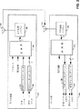
図2は、本発明の例示的な実施形態により構成された加入者装置およびベース局のブロック図である。
図3は、本発明の例示的な実施形態により構成されたBPSKチャンネルエンコーダとQPSKチャンネルエンコーダのブロック図である。
図4は、本発明の例示的な実施形態により構成された送信信号処理システムのブロック図である。
図5は、本発明の例示的な実施形態により構成された受信信号処理システムのブロック図である。
図6は、本発明の1実施形態により構成されたフィンガー処理システムのブロック図である。
図7は、本発明の例示的な実施形態により構成されたBPSKチャンネルデコーダとQPSKチャンネルデコーダのブロック図である。
[好ましい実施形態の説明]
高速度のCDMA無線通信のための優れた、改良された方法および装置はセルラ通信システムの逆方向リンク伝送部分について記載されている。本発明は、セルラ電話システムの多数の地点間逆方向リンク伝送内で使用するのに特に適しているが、本発明は、順方向リンク伝送にも同様に適用されることができる。さらに、衛星ベースの無線通信システム、地点間無線通信システム、同軸またはその他の広帯域ケーブルの使用による無線周波数信号を送信するシステム等を含む多くの他の無線通信システムが本発明を使用することによって利益を得ることができる。
図2は、本発明の1実施形態による加入者装置100およびベース局120として構成された受信および送信システムのブロック図である。第1の組のデータ(BPSKデータ)はBPSKチャンネルエンコーダ103によって受信され、このエンコーダ103はBPSK変調を行うように構成されたコードシンボルを発生し、それは変調器104によって受信される。第2の組のデータ(QPSKデータ)はQPSKチャンネルエンコーダ102によって受信され、このエンコーダ102はQPSK変調を行うように構成されたコードシンボルを発生し、それもまた変調器104によって受信される。変調器104はまた電力制御データおよびパイロットデータを受信し、それはコード分割多重アクセス(CDMA)技術にしたがってBPSKおよびQPSKのコード化されたデータと共に変調され、RF処理システム106によって受信される1組の変調シンボルを発生する。RF処理システム106はこの1組の変調シンボルを瀘波し、アンテナ108を使用してベース局120に送信ために搬送波周波数に上方変換する。ただ1つの加入者装置100しか示されていないが、この実施形態では多数の加入者装置がベース局120と通信する。
ベース局120内において、RF処理システム122は送信されたRF送信をアンテナ121により受信し、バンドパス瀘波、ベースバンドへの下方変換およびデジタル化を行う。復調器124はデジタル化された信号を受信してCDMA技術にしたがって復調を行い、電力制御、BPSK、およびQPSKソフト決定データを生成する。BPSKチャンネルデコーダ128は復調器124から受信されたBPSKソフト決定データを解読してBPSKデータの最良の評価を生成し、QPSKチャンネルデコーダ126は復調器124から受信されたQPSKソフト決定データを解読してQPSKデータの最良の評価を生成する。最良の評価の第1と第2のデータのセットはその後さらに処理するために使用され、或いは次の目的地へ送られ、受信された電力制御データは直接或いは解読後に加入者装置100にデータを送信するために使用された順方向リンクチャンネルの送信電力を調節するために使用される。
図3は、本発明の例示的な実施形態にしたがて構成されたBPSKチャンネルエンコーダ103とQPSKチャンネルエンコーダ102のブロック図である。BPSKチャンネルエンコーダ103内においてBPSKデータはCRCチェックサム発生器130により受信され、第1の組のデータのそれぞれ20msのフレームに対するCRCチェックサムを発生する。CRCチェックサムと共にデータフレームはテールビット発生器132によって受信され、それはデコードプロセスの終りにおいて既知の状態を与えるために各フレームの終りに8個の論理ゼロからなるテールビットを付加する。コードテールビットおよびCRCチェックサムを含むフレームはコンポリューションエンコーダ134によって受信され、このコンポリューションエンコーダ134は、制限された長さ(K)9、速度(R)1/4ノコンポリューションコード化を行い、それによってエンコーダ入力速度(ER)の4倍の速度のコードシンボルを発生する。本発明の別の実施形態では、1/2速度を含む他のコード化速度が実行されるが、その最適の複素数性能特性によって1/4速度が好ましい。ブロックインターリーバ136はコードシンボルについてビットインターリーブを行い、高速フェーディングの環境において信頼性の高い送信を行うために時間ダイバーシティを行う。その結果得られたインターリーブされたシンボルは可変スタート点リピータ138により受信され、それはインターリーブされたシンボルシーケンスを十分な回数NRで反復して一定速度のシンボル流を生成し、それは一定数のシンボルを有するフレームを出力することに対応している。シンボルシーケンスの反復はまたフェーディングを克服するためにデータの時間ダイバーシティを増加させる。例示的な実施形態において、一定数のシンボルは毎秒307.2キロシンボル(ksps)のシンボル速度を形成する各フレームに対して6,144シンボルに等しい。また、リピータ138は異なったスタート点を使用して各シンボルシーケンスに対して反復を開始する。フレーム当り6,144シンボルを発生するために必要なNRの値が整数でないとき、最終的な反復はシンボルシーケンスの一部に対してだけ行なわれる。結果的に得られた1組の反復されたシンボルはBPSKマッパ(mapper)139によって受信され、それはBPSKコードシンボル流(BPSK)の+1および−1値を生成し、BPSK変調を実行する。本発明の別の実施形態において、リピータ138はブロックインターリーバ136の前に配置され、そのためブロックインターリーバ136が各フレームに対して同じ数のシンボルを受信する。
QPSKチャンネルエンコーダ102内においてQPSKデータはCRCチェックサム発生器140により受信され、それぞれ20msのフレームに対するCRCチェックサムを発生する。CRCチェックサムを含むフレームはコードテールビット発生器142によって受信され、それはフレームの終りに8個の論理ゼロのテールビットを付加する。コードテールビットおよびCRCチェックサムを含むフレームはコンポリューションエンコーダ144によって受信され、このコンポリューションエンコーダ144は、K=9、R=1/4のコンポリューションコード化を行い、それによってエンコーダ入力速度(ER)の4倍の速度のコードシンボルを発生する。ブロックインターリーバ146はシンボルについてビットインターリーブを行い、結果的に得られたインターリーブされたシンボルは可変スタート点リピータ148により受信される。可変スタート点リピータ148はインターリーブされたシンボルシーケンスを各反復に対してシンボルシーケンス内の異なったスタート点を使用して十分な回数NR反復して毎秒614.4キロシンボル(ksps)のシンボル速度を形成する各フレームに対して12,288シンボルを発生する。NRの値が整数でないとき、最終的な反復はシンボルシーケンスの一部に対してだけ行なわれる。結果的に得られた反復されたシンボルはQPSKマッパ149によって受信され、それは同位相QPSKコードシンボル流の+1および−1の値(QPSKI)と直角位相QPSKコードシンボル流の+1および−1の値(QPSKQ)とからなるQPSK変調を実行するように構成されたQPSKコードシンボル流を生成する。本発明の別の実施形態において、リピータ148はブロックインターリーバ146の前に配置され、そのためブロックインターリーバ146が各フレームに対して同じ数のシンボルを受信する。
図4は、本発明の例示的な実施形態にしたがって構成された図2の変調器104のブロック図である。BPSKチャンネルエンコーダ103からのBPSKシンボルは乗算器150bを使用してウォルシュコードW2によってそれぞれ変調され、QPSKチャンネルエンコーダ102からのQPSKIおよびQPSKQシンボルは乗算器150cおよび150dを使用してウォルシュコードW3によってそれぞれ変調される。電力制御データ(PC)は乗算器150aを使用してウォルシュコードW1によって変調される。利得調節装置152はパイロットデータ(PILOT)を受信し、それは本発明の好ましい実施形態では正の電圧に関連する論理レベルから構成され、調節係数A0によって振幅を調節する。パイロット信号PILOTはユーザデータを与えるのではなく、ベース局に対して位相および振幅情報を提供し、それによって残っているサブチャンネルで伝送されたデータのコヒーレントな復調を可能にし、ソフト決定出力値を結合のためにスケールする。利得調節装置154は利得調節係数A1によってウォルシュコードW1で変調された電力制御データの振幅を調節する。利得調節装置156は増幅変数A2にしたがってウォルシュコードW2で変調されたBPSKチャンネルデータの振幅を調節する。利得調節装置158aおよび158bは利得調節係数A3にしたがってそれぞれウォルシュコードW3で変調された同位相および直角位相QPSKシンボルチャンネルデータの振幅を調節する。本発明の好ましい実施形態で使用されたウォルシュコードは表Iに示されている。

短い直交コードの使用はシンボル当りの発生するチップ数を少なくし、それ故長いウォルシュコードの使用を伴うシステムと比較したときより広範囲のコード化および反復が可能になる。このさらに広がったコード化および反復は地上通信システムにおけるエラーの主要な原因であるレーレーフェーディングに対する保護手段を与える。その他のコード数およびコード長の使用は本願発明に使用可能であるが、さらに長いウォルシュコードの大きいセットの使用はフェーディングに対する保護の効果の向上を減殺する。4チップコードの使用は最適であると考えられる。それは4つのチャンネルは以下示すように種々の形式のデータの伝送に対して十分な柔軟性を与え、しかも短いコード長を維持できるからである。
合計装置160は利得調節装置152,154,156,158aからの結果的に調節された変調信号を合計して合計された変調シンボル161を発生する。PN拡散コードPNIおよびPNQは乗算器162aおよび162bを使用してロングコード80との乗算により拡散される。乗算器162aおよび162bにより与えられた結果的に得られた疑似ランダムコードは合計された変調シンボル161を変調するために使用され、利得調節された直角位相シンボルQPSKQ163は乗算器164a〜dおよび合計装置166aおよび166bを使用して複素数乗算される。得られた同位相項XIおよび直角位相項XQは瀘波され(フィルタは示されていない)、RF処理システム106内で搬送波周波数に上方変換される。RF処理システム106は乗算168および同位相および直角位相正弦波を使用する簡単化された形態で示されている。オフセットQPSK上方変換はまた本発明の別の実施形態で使用されることができる。同位相および直角位相の上方変換された信号は合計装置170を使用して合計され、主増幅器172により主利得調節係数AMにしたがって増幅され、ベース局120に送信される信号s(t)を発生する。本発明の好ましい実施形態において、信号は拡散され瀘波されて1.2288MHzの帯域幅とされ、既存のCDMAチャンネルの帯域幅と匹敵するように維持される。
データが伝送される多重直交チャンネルを提供することによって、および高い入力データ速度に応答して行われるNR回の反復数を減少させる可変速度リピータを使用することによって、上述の送信信号処理方法およびシステムは、単一の加入者装置または他の送信システムが可変データ速度でデータを送信することを可能にする。特に、図3の可変スタート点リピータ138または48により行われる反復率NRを減少することによって増加する高いエンコーダ入力速度ERが維持されることができる。本発明の別の実施形態では1/2速度コンボリューションコード化が2倍に増加された反復割合NRにより行われる。種々の反復割合NRと、BPSKQチャンネルおよびPSKチャンネルに対する1/4および1/2に等しいコード化速度Rによりサポートされた1組の例示的なエンコーダ速度ERは表IIおよびIIIにそれぞれ記載されている。
データ送信速度はまた、反復速度NRの減少によって送信速度を増加するのに加えて、またはその増加の代わりに行われる2以上の多数の直交チャンネル上で同時にデータを送信することによって増加されることができる。例えばマルチプレクサ(図示せず)は1つのデータソースを、多数のデータサブチャンネルにわたって送信されるように多数のデータソースに分割する。したがって、受信システムの信号処理能力を超過し、エラー速度が許容可能ではなくなるかまたは送信システム電力の最大送信電力に到達するまで、総送信速度は、より高速度の特定のチャンネルによる送信、或いは多数のチャンネルによって同時に行われる多数の送信により増加されることができる。
多数のチャンネルはまた異なったタイプのデータの送信でフレキシブル性を強化することとする。例えば、BPSKチャンネルは音声情報を指定され、QPSKチャンネルはデジタルデータの送信を指定される。この実施形態はより低いデータ速度の音声等の時間感知性データを送信するために1チャンネルを指定し、他のチャンネルをデジタルファイル等の時間感知性の少ないデータの送信に指定することによってさらに一般化することができる。この実施形態ではインターリーブはさらに時間ダイバーシティを増加するために時間感知性の少ないデータのための大きなブロックで行われる。本発明の別の実施形態では、BPSKチャンネルはデータの主要な送信を行い、QPSKチャンネルはオーバーフロー送信を行う。直交ウォルシュコードの使用は加入者装置から送信されたチャンネルセット間の干渉を除去または実質上減少し、したがってベース局での適切な受信に必要な送信エネルギを最小限にする。
受信システムでの処理能力を増加し、それ故加入者装置におけるより高い送信能力が利用される程度を増加するために、パイロットデータはまた直交チャンネルのうちの1つにより送信される。パイロットデータを使用して、コヒーレントな処理が逆方向リンク信号の位相オフセットを決定し除去することによって受信システムで行われることができる。またパイロットデータはレイク(rake)受信機で結合される前に異なった時間遅延で受信されたマルチパス信号を最適に加重することに使用されることができる。一度位相オフセットが除去され、マルチパス信号が適切に加重されると、マルチパス信号は結合され、逆方向リンク信号が適切に処理されるように受信されなければならない電力を減少する。この必要な受信電力の減少は、より大きい送信速度が適切に処理されることを可能にし、または反対に逆方向リンク信号セット間の干渉が減少されることを可能にする。幾つかの付加的な送信電力がパイロット信号の送信に必要であり、より高い送信速度の環境ではパイロットチャンネル電力の全体的な逆方向リンク信号電力に対する比率は、より低いデータ送信のデジタル音声データ送信セルラシステムに関する比率よりも実質上低い。したがって、高いデータ速度のCDMAシステム内では、コヒーレントな逆方向リンクの使用で実現されたEb/N0利得は各加入者装置からパイロットデータを送信するのに必要な付加的な電力にまさっている。
利得調節装置152−158とマスター増幅器172の使用は、送信システムが種々の無線チャンネル状態、送信速度、データタイプに適合することを可能にすることによって、前述のシステムの高送信能力が利用されることができる程度をさらに増加する。特に、適切な受信に必要なチャンネルの送信電力は他の直交チャンネルと独立した方法で時間にわたって変化し、状況の変化で変化する。例えば、逆方向リンク信号の最初の捕捉期間中に、パイロットチャンネル電力はベース局において検出と同期を行うために増加される必要がある。しかしながら、一度逆方向リンク信号が得られると、パイロットチャンネルの必要な送信電力は実質上減少し、加入者装置の移動速度を含む種々の係数に依存して変化する。したがって、利得調節係数の値A0は信号捕捉中は増加し、その後、通信の進行中には減少する。別の例では、より多くのエラーの許容性を有する情報が順方向リンクにより送信されるとき、または順方向リンク送信が行われる環境がフェーディングを生じる傾向がないとき、利得調節係数A1は、低いエラー速度を有する電力制御データを送信する必要性が減少するとき減少される。本発明の1実施形態では、電力制御調節が必要でないときはいつでも、利得調節係数A1はゼロに減少される。
本発明の別の実施形態では、各直交チャンネルまたは逆方向リンク信号全体を利得調節する能力は、順方向リンク信号を介して送信される電力制御命令の使用により、ベース局120またはその他の受信システムがチャンネルまたは逆方向リンク信号全体の利得調節を変更することを可能にすることによってさらに利用される。特に、ベース局は特定のチャンネルまたは逆方向リンク信号全体の送信電力を調節するようにリクエストする電力制御情報を送信することもできる。これはデジタル化された音声およびデジタルデータ等のエラーに対して異なった感度を有する2つのタイプのデータがBPSKとQPSKチャンネルを経て送信されるときのような多数の例において有効である。この場合、ベース局120は2つの関連するチャンネルで異なったターゲットエラー速度を設定する。チャンネルの実際のエラー割合がターゲットエラー割合を越えたならば、ベース局は加入者装置に実際のエラー割合がターゲットエラー割合に到達するまでチャンネルの利得調節を減少するように指令する。これは最終的に一方のチャンネルの利得調節係数を他方のチャンネルの利得調節係数に関して増加させる。すなわち、より多くのエラー感知性のデータに関連する利得調節係数は、感知性の少ないデータに関する利得調節係数に関連して増加される。別の例では、逆方向リンク全体の送信電力は加入者装置100のフェーディング状況または移動のために調節を必要とする。これらの場合、ベース局120は1つの電力制御命令の送信によってこのように行うことができる。
したがって、4つの直交チャンネルの利得が独立して、および相互に結合して調節されることを可能にすることにより、逆方向リンク信号の全送信電力は、これがパイロットデータであるか、電力制御データであるか、シグナリングデータであるかまたは異なったタイプのユーザデータであるか等の各データタイプに対して適切に送信するために必要な最小の電力に維持されることができる。さらに、適切な送信は各データタイプにより異なって限定されることができる。必要最低限の電力による送信は、最大量のデータが、加入者装置の有限の送信電力能力が与えられたベース局に送信されることを可能にし、また加入者装置間の干渉を減少する。この干渉の減少はCDMA無線セルラシステム全体の総通信容量を増加する。
逆方向リンク信号で使用される電力制御チャンネルにより、加入者装置は毎秒800電力制御ビットの速度を含む種々の速度でベース局へ電力制御情報を送信することが可能である。本発明の好ましい実施形態では、電力制御ビットは情報を加入者装置に送信するために使用されている順方向リンク通信チャンネルの送信電力を増加または減少するようにベース局に指令する。通常、CDMAシステム内で迅速な電力制御を行うことが有効であるが、デジタルデータはエラーに対してより敏感であり、高送信は短いフェーディング状態でさえも相当量のデータの損失を招くので、これはデータ送信を含むより高いデータ速度通信の面では特に便利である。高速度逆方向リンク送信が高速度順方向リンク送信を伴う傾向があると、逆方向リンクにおける電力制御の迅速な伝送を行うことはさらにCDMA無線通信システム内で高速度通信を助長する。
本発明の別の例示的な実施形態では、特定のNRにより定められる1組のエンコーダ入力速度ERが特定のタイプのデータの送信に使用される。すなわち、データは最大のエンコーダ入力速度ER、またはより低いエンコーダ入力装置ERのセットで送信され、関連するNRはしたがって調節される。この実施形態の好ましい構成では、最大速度は表II、IIIでRS1−全速度とRS2−全速度に関して前述したようにIS−95コンプライアント無線通信システムで使用される最大速度に対応し、それぞれの低い速度は次に高い速度のほぼ半分であり、全速度、半速度、4分の1速度、8分の1速度からなる1組の速度を生成する。より低いデータ速度は、表IV与えられているBPSKチャンネルの速度セット1、速度セット2に対する値NRでシンボル反復速度NRを増加することによって生成されることが好ましい。
本発明の例示的な実施形態にしたがって、フレームのデータ速度が先のフレームに関して変化したとき、フレームの送信電力は送信速度の変化にしたがって調節される。すなわち、低い速度のフレームが高い速度のフレームの後で送信されるとき、フレームが送信されている送信チャンネルの送信電力は速度減少に比例して低い速度のフレームに対して減少され、またはその逆である。例えば、全速度のフレームの送信期間のチャンネルの送信電力が送信電力Tであるならば、半速度のフレームの結果的な送信期間の送信電力はT/2である。送信電力の減少は好ましくはフレームの全期間の送信電力を減少することによって行われるのではなく、幾らかの冗長情報が“ブランクアウト”されるように送信デューティサイクルを減少することによっても行われることもできる。どちらの場合でも、送信電力調節は閉ループ電力制御機構と組み合わせて行われ、それによって送信電力はベース局から送信された電力制御データに応答してさらに調節される。
図5は本発明の例示的な実施形態にしたがって構成された図2のRF処理システム122と復調器124のブロック図である。乗算器180aと180bは、同位相正弦波と直角位相正弦波によりアンテナ121から受信した信号を下方変換し、それぞれ同位相受信サンプルRIと直角位相受信サンプルRQを生成する。RF処理システム122は非常に簡単な形態で示されており、信号も広く知られた技術にしたがって整合フィルタ処理され、デジタル化される(図示せず)ことを理解すべきである。その後、受信サンプルRIとRQは復調器124内のフィンガ復調器182に供給される。各フィンガ復調器182は、インスタンスが利用可能であるならば、加入者装置100により送信された逆方向リンク信号のインスタンスを処理し、逆方向リンク信号の各インスタンスはマルチパス現象により生成される。3つのフィンガ復調器が示されているが、単一のフィンガ復調器182の使用を含む別の数のフィンガ復調器を使用することも本発明と適合している。各フィンガ復調器182は1組のソフト決定データを生成し、これは電力制御データ、BPSKデータ、QPSKIデータおよびQPSKQデータからなる。本発明の別の実施形態では時間調節は結合器184内で行われるが、各セットのソフト決定データはまた対応するフィンガ復調器182内で時間調節される。その後、結合器184はフィンガ復調器182から受信したソフト決定データのセットを合計し、電力制御、BPSK、QPSKIおよびQPSKQのソフト決定データの1つのインスタンスを生成する。
図6は本発明の例示的な実施形態にしたがって構成された図5のフィンガ復調器182のブロック図である。RI、RQ受信サンプルは、処理される逆方向リンク信号の特定のインスタンスの送信路により生じた遅延量にしたがって、時間調節装置190を使用して最初に調節される。ロングコード200は乗算器201を使用して疑似ランダム拡散コードPNI、PNQと混合され、結果的なロングコードの変調されたPNI、PNQ拡散コードの複素数共役は乗算器202と合計器204を使用して、時間調節されたRI、RQ受信サンプルと複素数乗算され、項XI、XQを生成する。XI、XQ項の3つの別々のインスタンスはその後、それぞれウォルシュコードW1、W2、W3を使用して復調され、結果的なウォルシュ復調されたデータは4〜1の合計器212を使用して4つの復調チップにわたって合計される。XI、XQデータの4番目のインスタンスは合計器208を使用して4つの復調チップにわたって合計され、その後、パイロットフィルタ214を使用してフィルタ処理される。本発明の好ましい実施形態では、パイロットフィルタ214は合計器208により行われた一連の合計にわたって平均を行うが、他のフィルタリング技術は当業者に明白である。フィルタ処理された同位相および直角位相パイロット信号は、乗算器216と加算器217を使用して、複素数共役乗算によりBPSK変調されたデータにしたがってW1、W2ウォルシュコードで復調されたデータを位相回転し、スケールするために使用され、それによってソフト決定電力制御とBPSKデータを生成する。W3ウォルシュコードで変調されたデータは、乗算器218と加算器220を使用して、QPSK変調されたデータにしたがって同位相および直角位相のフィルタ処理されたパイロット信号を用いて位相回転され、それによってソフト決定QPSKデータを生成する。ソフト決定電力制御データは384対1の合計器222により384の変調シンボルにわたって合計され、電力制御ソフト決定データを生成する。位相回転されたW2ウォルシュコードで変調されたデータと、W3ウォルシュコードで変調されたデータと、電力制御ソフト決定データはその後、結合のために利用可能にされる。本発明の別の実施形態では、エンコードとデコードは同様に電力制御データについて行われる。
位相情報を提供することに加えて、パイロットは時間追跡を行うために受信システム内で使用されてもよい。時間追跡は、1サンプル時間前(早期)と1サンプル時間後(後期)で受信データを処理することによっても行われ、現在の受信サンプルが処理される。実際の到着時間に最も近く一致する時間を決定するため、早期および後期サンプル時間におけるパイロットチャンネルの振幅は現在のサンプル時間における振幅と比較されることができ、したがって最大のものが決定される。近接するサンプル時間のうちの1つのサンプル時間の信号が現在のサンプル時間の信号よりも大きいならば、最良の復調結果が得られるようにそのタイミングが調節されることができる。
図7は本発明の例示的な実施形態にしたがって構成されたBPSKチャンネルデコーダ128とQPSKチャンネルデコーダ126(図2)のブロック図である。結合器184(図5)からのBPSKソフト決定データは累算器240により受信され、この累算器は受信されたフレーム中の6,144/NR復調シンボルの第1のシーケンスを記憶し、ここでNRは前述したようにBPSKソフト決定データの送信速度に依存し、フレームに含まれている6,144/NR復調シンボルのそれぞれの後続するセットを、対応する記憶された累算シンボルと加算する。ブロックインターリーバ242は可変スタート点合計器240からの累算されたソフト決定データをデインターリーブし、ビタビデコード244はデインターリーブされたソフト決定データをデコードして、ハード決定データとCRCチェックサム結果とを生成する。QPSKデコーダ126内で、結合器184(図5)からのQPSKI、QPSKQソフト決定データはデマルチプレクサ246により1つのソフト決定データ流へ分解され、単一のソフト決定データ流は累算器248により受信され、この累算器248はQPSKデータの送信速度に応じて、毎回6,144/NR復調シンボルを累積し、ここでNRはQPSKデータの送信速度に依存している。ブロックデインターリーバ250は可変のスタート点合計器248からのソフト決定データをデインターリーブし、ビタビデコード252はデインターリーブされた変調シンボルをデコードし、それによってハード決定データとCRCチェックサム結果を生成する。シンボル反復がインターリーブ前に行われる図3に関して前述した別の実施形態では、累算器240、248はブロックデインターリーバ242、250の後に置かれている。速度セットを使用し、そのため特定のフレームの速度が知られていない本発明の実施形態では、多数のデコーダが使用され、それぞれ異なった送信速度で動作し、使用される可能性が最も高い送信速度に関連するフレームはCRCチェックサム結果に基づいて選択される。他のエラーチェック方法の使用もまた本発明の実用に適合している。
以上、マルチチャンネルで高速度のCDMA無線通信システムを説明した。この説明は当業者が本発明を実行または使用することを可能にするために行ったものである。これらの実施形態に対する種々の変形は当業者に明白であり、ここで限定されている一般原理は発明力を要せずに他の実施形態に適用されることができる。したがって本発明はここで示されている実施形態に限定されるものではなく、ここで説明されている原理およびすぐれた特徴と調和する広い技術的範囲に従うことを意図している。[Background of the invention]
1. TECHNICAL FIELD OF THE INVENTION
The present invention relates to communication systems, and more particularly to an improved and improved method and apparatus for high data rate CDMA wireless communication.
2. Description of the technology involved
Wireless communication systems, including cellular, satellite, and point-to-point communication systems, use radio links that include modulated radio frequency (RF) signals for data transmission between the two systems. The use of wireless links is preferred for a variety of reasons, such as increased mobility and reduced demand for infrastructure as compared to wired communication systems. One of the disadvantages of using wireless links is the limited capacity that results from the limited amount of RF bandwidth available. This limited communication capacity is in contrast to wired-based communication, where additional capacity can be added by installing additional wired line connections.
Recognizing the limited nature of RF bandwidth, various signal processing techniques have been developed that increase the efficiency with which wireless communication systems use effective RF bandwidth. One widely accepted example of such bandwidth efficient signal processing technology is the IS-95 and the developed IS-95A (hereinafter referred to as the air interface standard) published by the Telecommunications Industry Association (TIA). Are collectively referred to as the IS-95 standard system), and is mainly used in cellular communication systems. The IS-95 standard system includes code division multiple access (CDMA) signal modulation techniques, and performs multiple communications simultaneously over the same RF bandwidth. When combined with comprehensive power control, multiple communications over the same bandwidth increases the overall number of calls and increases frequency reuse compared to other wireless communication technologies.
The use of CDMA technology in a multiple access communication system is described in Applicant's US Pat. No. 4,901,307 and US Pat. No. 5,103,459, where references and Is done.
FIG. 1 is a highly simplified drawing of a cellular telephone system configured according to the IS-95 standard. In operation, a set of subscriber devices 10a-d communicate wirelessly by setting up one or more RF interfaces with one or
According to the IS-95 standard, each subscriber unit 10 transmits user data over a single channel, non-coherent, reverse link signal at a maximum data rate of 9.6 or 14.4 kbit / s. It relies on a speed setting selected from a set of speeds. A non-coherent link is a link whose phase information is not utilized by the receiving system. A coherent link is a link in which the receiver uses knowledge of the phase of the carrier signal during processing. The phase information generally takes the form of a pilot signal, but can also be estimated from the transmitted data. Each IS-95 standard call for a set of 64 Walsh codes consists of 64 chips each used for the forward link.
The use of a single channel, non-coherent, reverse link signal with a maximum data rate of 9.6 or 14.4 kbit / s as specified by the IS-95 standard is well suited for wireless cellular telephone systems. In that, typical communications include digitized voice or low speed data such as Faximil. A non-coherent reverse link can communicate with the base station for each band with a bandwidth of 1.2288 MHz each allocated up to 80 subscriber devices 10 and a set of subscriber devices 10 interfere with each other. Necessary pilot data is provided during transmission from each subscriber device 10 to substantially increase the degree. Also, the ratio of pilot data to user data at a data rate of 9.6 or 14.4 kbit / s is significant, thus increasing interference between subscriber units. Since the use of single channel reverse link signals combines in one type of communication at a time that is compatible with the use of wired telephones, there is an exemplary basis for current wireless cellular communications. Also, the single channel processing complexity is less than that associated with processing multiple channels.
With advances in digital communications, the desire for wireless transmission of data for applications such as interactive file listing and video teleconference is expected to increase substantially. This increase changes the way in which wireless communication systems are used and the conditions under which the associated RF interface operates. In particular, data will be transmitted at a high maximum rate and a great many possible types. In addition, more reliable transmission is required. This is because the tolerance of errors in transmission data becomes stricter than in the case of transmission of audio information. Furthermore, the increase in data types creates the need to send multiple types of data at the same time. For example, it is necessary to exchange data files, while maintaining an audio or video interface. Also, as the transmission rate from the subscriber unit increases, the number of subscriber units 10 communicating with the base station 12 per amount of RF bandwidth decreases. The higher the data transmission rate, the less the data processing capacity of the base station reaches the base station 10. In one example, the current IS-95 standard reverse link cannot ideally adapt to all these changes. Therefore, the present invention relates to providing a CDMA interface in which higher data rates, bandwidth efficiency, and multiple types of communication are performed.
[Summary of Invention]
An improved and improved method and apparatus for high speed CDMA wireless devices is disclosed. According to one embodiment of the present invention, a set of gain adjusted subscriber channels is formed by using a set of orthogonal subchannel codes having a small number of PN spreading chips per orthogonal waveform period. The data to be transmitted over one of the transmission channels is a coded low code rate error correction, and the repeated sequence is modulated by one of the subchannel codes, gain adjusted, and the other subchannel Summed with data modulated using code. The resulting summed data is modulated using a long code and pseudo-spreading code (PN code) and up-converted for transmission. The use of short orthogonal codes suppresses interference while still allowing for wide error correction coding and reception against time diversity to overcome the Rayleigh fading normally experienced in terrestrial radio systems. According to one embodiment of the present invention, a set of subchannel codes consists of four Walsh codes, each orthogonal to the remaining set and having a 4-chip period. The use of four subchannels is preferred because the orthogonal code used can be shortened. However, the use of a larger number of channels, ie longer codes, is consistent with the present invention.
In a preferred embodiment of the present invention, pilot data is transmitted over a first transmission channel and power control data is transmitted over a second transmission channel. The remaining two transmission channels are used to transmit unspecified digital data including user data, signaling data or both. In the exemplary embodiment, one of the two unspecified transmission channels is configured for BPSK modulation and the other is configured for QPSK modulation. In order for this to be done, it indicates the pluripotency of the system. Both channels can be BPSK modulated or QPSK modulated in another embodiment of the invention. Prior to modulation, unspecified data is coded, which includes cyclic redundancy check (CRC) generation, convolution coding, interleaving, selective sequence repetition, and BPSK or QPSK mapping. By varying the number of iterations performed, a wide variety of transmission rates can be obtained, including high data rates, without being limited to the number of iterations for an integer symbol sequence. Higher data rates can be achieved by transmitting data on both unspecified channels simultaneously. Also, by frequently updating the gain adjustment performed on each transmission channel, the overall transmission power used by the transmission system minimizes the interference generated between multiplex transmission systems, thereby increasing the overall system capacity. Can be kept to a minimum.
[Brief description of the drawings]
The features, objects and advantages of the present invention will become more apparent from the following detailed description when taken in conjunction with the accompanying drawings. In the drawings, like reference numerals designate corresponding parts throughout.
FIG. 1 is a block diagram of a cellular telephone system.
FIG. 2 is a block diagram of a subscriber unit and a base station configured in accordance with an exemplary embodiment of the present invention.
FIG. 3 is a block diagram of a BPSK channel encoder and a QPSK channel encoder configured in accordance with an exemplary embodiment of the present invention.
FIG. 4 is a block diagram of a transmit signal processing system configured in accordance with an exemplary embodiment of the present invention.
FIG. 5 is a block diagram of a received signal processing system configured in accordance with an exemplary embodiment of the present invention.
FIG. 6 is a block diagram of a finger processing system configured in accordance with one embodiment of the present invention.
FIG. 7 is a block diagram of a BPSK channel decoder and a QPSK channel decoder configured according to an exemplary embodiment of the present invention.
[Description of Preferred Embodiment]
An improved and improved method and apparatus for high speed CDMA wireless communication is described for the reverse link transmission portion of a cellular communication system. Although the present invention is particularly suitable for use in multiple point-to-point reverse link transmissions in cellular telephone systems, the present invention can be applied to forward link transmissions as well. In addition, many other wireless communication systems, including satellite-based wireless communication systems, point-to-point wireless communication systems, systems that transmit radio frequency signals through the use of coaxial or other broadband cables, etc., benefit from using the present invention. Can be obtained.
FIG. 2 is a block diagram of a reception and transmission system configured as a
Within the
FIG. 3 is a block diagram of a
Within the
FIG. 4 is a block diagram of the
The use of short orthogonal codes reduces the number of chips generated per symbol and thus allows a wider range of coding and repetition when compared to systems involving the use of long Walsh codes. This more extensive coding and repetition provides protection against Rayleigh fading, which is a major cause of errors in terrestrial communication systems. The use of other code numbers and code lengths can be used in the present invention, but the use of a larger set of longer Walsh codes diminishes the effectiveness of protection against fading. The use of a 4-chip code is considered optimal. This is because the four channels provide sufficient flexibility for the transmission of various types of data, as shown below, while maintaining a short code length.
Summing
N performed by providing multiple orthogonal channels over which data is transmitted and in response to high input data rates R By using a variable rate repeater that reduces the number of iterations, the transmit signal processing method and system described above allows a single subscriber unit or other transmission system to transmit data at a variable data rate. To do. In particular, the repetition rate N performed by the variable
The data transmission rate is also the repetition rate N R Can be increased by transmitting data simultaneously on two or more multiple orthogonal channels in addition to or in lieu of increasing the transmission rate by reducing. For example, a multiplexer (not shown) divides one data source into multiple data sources for transmission over multiple data subchannels. Thus, the total transmission rate can be transmitted over a specific channel at a higher rate or many times until the signal processing capability of the receiving system is exceeded and the error rate is not acceptable or reaches the maximum transmission power of the transmission system power. Can be increased by multiple transmissions simultaneously performed by different channels.
Multiple channels will also enhance flexibility with the transmission of different types of data. For example, the BPSK channel is designated for audio information, and the QPSK channel is designated for transmission of digital data. This embodiment is further generalized by designating one channel to transmit time sensitive data such as lower data rate voice and other channels for transmitting less time sensitive data such as digital files. Can be In this embodiment, interleaving is done in large blocks for less time sensitive data to further increase time diversity. In another embodiment of the present invention, the BPSK channel performs the main transmission of data and the QPSK channel performs the overflow transmission. The use of orthogonal Walsh codes eliminates or substantially reduces interference between channel sets transmitted from the subscriber unit, thus minimizing the transmission energy required for proper reception at the base station.
In order to increase the processing capacity at the receiving system and hence the extent to which higher transmission capacity at the subscriber unit is utilized, the pilot data is also transmitted over one of the orthogonal channels. Using the pilot data, coherent processing can be performed at the receiving system by determining and removing the phase offset of the reverse link signal. The pilot data can also be used to optimally weight multipath signals received with different time delays before being combined at a rake receiver. Once the phase offset is removed and the multipath signals are properly weighted, the multipath signals are combined, reducing the power that must be received so that the reverse link signal is properly processed. This required reduction in received power allows larger transmission rates to be handled properly, or conversely, allows interference between reverse link signal sets to be reduced. Some additional transmit power is needed for pilot signal transmission, and in higher transmission rate environments, the ratio of pilot channel power to overall reverse link signal power is lower than the digital voice data transmission for data transmission. Substantially lower than the ratio for cellular systems. Thus, in a high data rate CDMA system, the E realized with the use of a coherent reverse link. b / N 0 The gain surpasses the additional power required to transmit pilot data from each subscriber unit.
The use of gain adjusters 152-158 and
In another embodiment of the present invention, the ability to gain adjust each orthogonal channel or the entire reverse link signal may be based on the use of power control commands transmitted over the forward link signal,
Thus, by allowing the gains of the four orthogonal channels to be adjusted independently and in combination with each other, the total transmit power of the reverse link signal can be either pilot data or power control data. , Signaling data, or different types of user data, etc., can be maintained at the minimum power required to properly transmit for each data type. Furthermore, proper transmission can be limited differently for each data type. Transmission with the minimum required power allows the maximum amount of data to be transmitted to a base station given the subscriber device's finite transmit power capability and also reduces interference between subscriber devices. This reduction in interference increases the total communication capacity of the entire CDMA radio cellular system.
The power control channel used in the reverse link signal allows the subscriber unit to transmit power control information to the base station at various rates, including a rate of 800 power control bits per second. In the preferred embodiment of the present invention, the power control bits command the base station to increase or decrease the transmit power of the forward link communication channel being used to transmit information to the subscriber unit. While it is usually effective to perform rapid power control within a CDMA system, digital data is more sensitive to errors and high transmissions can cause a significant amount of data loss even in short fading conditions. This is particularly convenient in terms of higher data rate communications, including data transmission. As high-speed reverse link transmission tends to accompany high-speed forward link transmission, rapid transmission of power control on the reverse link further facilitates high-speed communication within a CDMA wireless communication system.
In another exemplary embodiment of the invention, a specific N R A set of encoder input speeds E determined by R Are used to transmit specific types of data. That is, the data is the maximum encoder input speed E R Or lower encoder input device E R N and the associated N R Is adjusted accordingly. In a preferred configuration of this embodiment, the maximum speed corresponds to the maximum speed used in an IS-95 compliant wireless communication system as described above in Tables II and III for RS1-full speed and RS2-full speed, The lower speed is approximately half of the next higher speed, producing a set of speeds consisting of full speed, half speed, quarter speed, and eighth speed. The lower data rate is the value N for rate set 1, rate set 2 for the BPSK channel given in Table IV. R Symbol repetition rate N R Preferably it is produced by increasing.
According to an exemplary embodiment of the present invention, when the data rate of a frame changes with respect to a previous frame, the transmission power of the frame is adjusted according to the change in transmission rate. That is, when a low rate frame is transmitted after a high rate frame, the transmission power of the transmission channel on which the frame is being transmitted is reduced relative to the rate decrease, and vice versa. It is. For example, if the transmission power of the channel during the transmission period of the full rate frame is the transmission power T, the transmission power of the resultant transmission period of the half rate frame is T / 2. The transmission power reduction is preferably not done by reducing the transmission power for the entire duration of the frame, but also by reducing the transmission duty cycle so that some redundant information is “blanked out”. You can also In either case, transmit power adjustment is performed in combination with a closed loop power control mechanism, whereby the transmit power is further adjusted in response to power control data transmitted from the base station.
FIG. 5 is a block diagram of the
FIG. 6 is a block diagram of
In addition to providing phase information, the pilot may be used in the receiving system to perform time tracking. Time tracking is also performed by processing the received data one sample time ago (early) and one sample time later (late) to process the current received sample. In order to determine the time that most closely matches the actual arrival time, the amplitude of the pilot channel at the early and late sample times can be compared with the amplitude at the current sample time, and therefore the maximum is determined. If the signal of one of the adjacent sample times is greater than the signal of the current sample time, the timing can be adjusted to obtain the best demodulation result.
FIG. 7 is a block diagram of a
The multi-channel high-speed CDMA wireless communication system has been described above. This description is made to enable one skilled in the art to make and use the invention. Various modifications to these embodiments will be apparent to those skilled in the art, and the generic principles limited herein may be applied to other embodiments without requiring inventive ability. Accordingly, the present invention is not intended to be limited to the embodiments shown herein, but is to be accorded the wide technical scope consistent with the principles and superior features described herein.
Claims (56)
複数のチャンネルのコード化されたデータのそれぞれを関連するコードにより変調して変調されたシンボルの複数のシンボル流を生成することと、
変調されたシンボルの複数のシンボル流を少なくとも1つの結合されたシンボル流に結合することと、
前記少なくとも1つの結合されたシンボル流を複素数疑似雑音コードにより複素数乗算することとを含み、
複数のチャンネルのコード化されたデータのそれぞれを関連するコードにより変調することは、
パイロットチャンネルのコード化されたデータを第1のコードにより変調して変調されたシンボルの第1のシンボル流を生成することと、
ユーザの第1のチャンネルのコード化されたデータを第2のコードにより変調して変調されたシンボルの第2のシンボル流を生成することと、
ユーザの第2のチャンネルのコード化されたデータを第2のコードにより変調して変調されたシンボルの第3のシンボル流を生成することとを含んでいるデータ発生方法。In a method for generating data to be transmitted from a subscriber unit to a base station,
Modulating each of the encoded data of the plurality of channels with an associated code to generate a plurality of symbol streams of modulated symbols;
Combining a plurality of symbol streams of modulated symbols into at least one combined symbol stream;
Complex multiplication of the at least one combined symbol stream by a complex pseudo-noise code;
Modulating each of the coded data of multiple channels with an associated code is
Modulating the pilot channel coded data with a first code to generate a first symbol stream of modulated symbols;
Modulating the coded data of the user's first channel with a second code to generate a second symbol stream of modulated symbols ;
A method of generating data comprising modulating the coded data of a user's second channel with a second code to generate a third symbol stream of modulated symbols .
前記変調されたシンボルの第1のシンボル流と、前記変調されたシンボルの第2のシンボル流と、前記変調されたシンボルの第4のシンボル流とを加算することと、
前記加算されたシンボル流を前記複素数乗算のために前記変調されたシンボルの第5のシンボル流とは独立して提供することとを含んでいる請求項3記載の方法。Combining a plurality of symbol streams of the modulated symbols comprises
Adding the first symbol stream of the modulated symbol, the second symbol stream of the modulated symbol, and the fourth symbol stream of the modulated symbol;
4. The method of claim 3 , comprising: providing the summed symbol stream independently of a fifth symbol stream of the modulated symbols for the complex multiplication.
前記変調されたシンボルの第1のシンボル流と、前記変調されたシンボルの第2のシンボル流と、前記変調されたシンボルの第4のシンボル流と、前記変調されたシンボルの第8のシンボル流とを加算することと、
前記加算されたシンボル流を前記複素数乗算のために前記変調されたシンボルの第5のシンボル流とは独立して提供することを含んでいる請求項5記載の方法。Combining a plurality of symbol streams of the modulated symbols comprises
A first symbol stream of the modulated symbols; a second symbol stream of the modulated symbols; a fourth symbol stream of the modulated symbols; and an eighth symbol stream of the modulated symbols. And adding
6. The method of claim 5 , comprising providing the summed symbol stream independently of a fifth symbol stream of the modulated symbols for the complex multiplication.
複数のチャンネルのコード化されたデータのそれぞれを関連するコードにより変調して変調されたシンボルの複数のシンボル流を生成することと、
変調されたシンボルの複数のシンボル流を少なくとも1つの結合されたシンボル流に結合することと、
前記少なくとも1つの結合されたシンボル流を複素数疑似雑音コードにより複素数乗算することとを含み、
複数のチャンネルのコード化されたデータのそれぞれを関連するコードにより変調することは、
パイロットチャンネルのコード化されたデータを第1のコードにより変調して変調されたシンボルの第1のシンボル流を生成することと、
ユーザの第3のチャンネルのコード化されたデータを第3のコードにより変調して変調されたシンボルの第4および第5のシンボル流を生成することと、
ユーザの第4のチャンネルのコード化されたデータを第4のコードにより変調して変調されたシンボルの第6および第7のシンボル流を生成することとを含んでいるデータ発生方法。In a method for generating data to be transmitted from a subscriber unit to a base station,
Modulating each of the encoded data of the plurality of channels with an associated code to generate a plurality of symbol streams of modulated symbols;
Combining a plurality of symbol streams of modulated symbols into at least one combined symbol stream;
Complex multiplication of the at least one combined symbol stream by a complex pseudo-noise code;
Modulating each of the coded data of multiple channels with an associated code is
Modulating the pilot channel coded data with a first code to generate a first symbol stream of modulated symbols;
Modulating the third channel coded data of the user with the third code to generate fourth and fifth symbol streams of modulated symbols;
A method of generating data comprising: modulating coded data of a user's fourth channel with a fourth code to generate sixth and seventh symbol streams of modulated symbols.
複数のチャンネルのコード化されたデータのそれぞれを関連するコードにより変調して変調されたシンボルの複数のシンボル流を生成することと、
変調されたシンボルの複数のシンボル流を少なくとも1つの結合されたシンボル流に結合することと、
前記少なくとも1つの結合されたシンボル流を複素数疑似雑音コードにより複素数乗算することとを含み、
前記複素数乗算することは、
少なくとも1つの結合されたシンボル流と、同位相疑似雑音コード成分とを実数部として使用することと、
少なくとも1つのシンボル流と、直角位相疑似雑音コード成分とを虚数部として使用することとを含んでいるデータ発生方法。In a method for generating data to be transmitted from a subscriber unit to a base station,
Modulating each of the encoded data of the plurality of channels with an associated code to generate a plurality of symbol streams of modulated symbols;
Combining a plurality of symbol streams of modulated symbols into at least one combined symbol stream;
Complex multiplication of the at least one combined symbol stream by a complex pseudo-noise code;
The complex multiplication is
Using at least one combined symbol stream and an in-phase pseudo-noise code component as real parts;
At least one symbol stream and the data generating method and a using a quadrature pseudo noise code component as imaginary parts.
少なくとも1つの結合されたシンボル流を同位相疑似雑音コード成分と乗算して第1の中間信号を生成することと、
少なくとも1つのシンボル流を同位相疑似雑音コード成分と乗算して第2の中間信号を生成することと、
少なくとも1つの結合されたシンボル流を直角位相疑似雑音コード成分と乗算して第3の中間信号を生成することと、
少なくとも1つのシンボル流を直角位相疑似雑音コード成分と乗算して第4の中間信号を生成することと、
第4の中間信号を第1の中間信号から減算して同位相の積信号を生成することと、
第2の中間信号を第3の中間信号に加算して直角位相の積信号を生成することとを含んでいる請求項18記載の方法。The complex multiplication is
Multiplying at least one combined symbol stream with an in- phase pseudo-noise code component to generate a first intermediate signal;
Generating a second intermediate signal at least one symbol stream by multiplying the in-phase pseudonoise code component,
Multiplying at least one combined symbol stream by a quadrature pseudo-noise code component to generate a third intermediate signal;
Generating a fourth intermediate signal by multiplying at least one symbol stream quadrature pseudo noise code component,
Subtracting the fourth intermediate signal from the first intermediate signal to generate an in-phase product signal;
The method of claim 18 including adding the second intermediate signal to the third intermediate signal to produce a quadrature product signal.
複数のチャンネルのコード化されたデータのそれぞれを関連するコードにより変調して変調されたシンボルの複数のシンボル流を生成することと、
変調されたシンボルの複数のシンボル流を少なくとも1つの結合されたシンボル流に結合することと、
前記少なくとも1つの結合されたシンボル流を複素数疑似雑音コードにより複素数乗算することとを含み、
変調されたシンボルの複数のシンボル流のそれぞれの利得を調節することをさらに含み、
前記変調されたシンボルの複数のシンボル流のそれぞれの利得を調節することは、
変調されたシンボルの第1のシンボル流の利得を調節することと、
残りのシンボル流のそれぞれの利得を、第1のシンボル流の利得に関して決定された値に調節することとを含んでいるデータ発生方法。In a method for generating data to be transmitted from a subscriber unit to a base station,
Modulating each of the encoded data of the plurality of channels with an associated code to generate a plurality of symbol streams of modulated symbols;
Combining a plurality of symbol streams of modulated symbols into at least one combined symbol stream;
Complex multiplication of the at least one combined symbol stream by a complex pseudo-noise code;
Further comprising adjusting the gain of each of the plurality of symbol streams of the modulated symbols;
Adjusting the gain of each of the plurality of symbol streams of the modulated symbols;
Adjusting the gain of the first symbol stream of the modulated symbols;
Adjusting the gain of each of the remaining symbol streams to a value determined with respect to the gain of the first symbol stream.
複数のチャンネルのコード化されたデータのそれぞれを関連するコードにより変調して変調されたシンボルの複数のシンボル流を生成する手段と、
変調されたシンボルの複数のシンボル流を結合して少なくとも1つの結合されたシンボル流にする結合手段と、
前記少なくとも1つの結合されたシンボル流を複素数疑似雑音コードにより複素数乗算する手段とを具備し、
複数のチャンネルのコード化されたデータのそれぞれを関連するコードにより変調する手段は、
パイロットチャンネルのコード化されたデータを第1のコードにより変調して変調されたシンボルの第1のシンボル流を生成する手段と、
ユーザの第1のチャンネルのコード化されたデータを第2のコードにより変調して変調されたシンボルの第2のシンボル流を生成する手段と、
ユーザの第2のチャンネルのコード化されたデータを第2のコードにより変調して変調されたシンボルの第3のシンボル流を生成する手段とを備えているデータ発生装置。In an apparatus for generating data to be transmitted from a subscriber apparatus to a base station,
Means for modulating each of a plurality of channels of encoded data with an associated code to generate a plurality of symbol streams of modulated symbols;
Combining means for combining a plurality of symbol streams of modulated symbols into at least one combined symbol stream;
Means for complex multiplication of the at least one combined symbol stream by a complex pseudo-noise code;
Means for modulating each of the encoded data of the plurality of channels with an associated code;
Means for modulating the coded data of the pilot channel with a first code to generate a first symbol stream of modulated symbols;
Means for modulating the coded data of the user's first channel with a second code to generate a second symbol stream of modulated symbols ;
Means for modulating the coded data of the user's second channel with the second code to generate a third symbol stream of the modulated symbols .
前記変調されたシンボルの第1のシンボル流と、前記変調されたシンボルの第2のシンボル流と、前記変調されたシンボルの第4のシンボル流とを加算する手段と、
前記加算されたシンボル流を前記複素数乗算のために前記変調されたシンボルの第5のシンボル流とは独立して提供する手段とを備えている請求項31記載の装置。Means for combining a plurality of symbol streams of the modulated symbols;
Means for adding a first symbol stream of the modulated symbol, a second symbol stream of the modulated symbol, and a fourth symbol stream of the modulated symbol;
32. The apparatus of claim 31, comprising means for providing the summed symbol stream independently of a fifth symbol stream of the modulated symbols for the complex multiplication.
前記変調されたシンボルの第1のシンボル流と、前記変調されたシンボルの第2のシンボル流と、前記変調されたシンボルの第4のシンボル流と、前記変調されたシンボルの第8のシンボル流とを加算する手段と、
前記加算されたシンボルのシンボル流を前記複素数乗算のために前記変調されたシンボルの第5のシンボル流とは独立して提供する手段とを備えている請求項33記載の装置。Means for combining a plurality of symbol streams of the modulated symbols;
A first symbol stream of the modulated symbols; a second symbol stream of the modulated symbols; a fourth symbol stream of the modulated symbols; and an eighth symbol stream of the modulated symbols. Means for adding and
34. The apparatus of claim 33, comprising means for providing a symbol stream of the summed symbols independently of a fifth symbol stream of the modulated symbols for the complex multiplication.
複数のチャンネルのコード化されたデータのそれぞれを関連するコードにより変調して変調されたシンボルの複数のシンボル流を生成する手段と、
変調されたシンボルの複数のシンボル流を結合して少なくとも1つの結合されたシンボル流にする結合手段と、
前記少なくとも1つの結合されたシンボル流を複素数疑似雑音コードにより複素数乗算する手段とを具備し、
複数のチャンネルのコード化されたデータのそれぞれを関連するコードにより変調する手段は、
パイロットチャンネルのコード化されたデータを第1のコードにより変調して変調されたシンボルの第1のシンボル流を生成する手段と、
ユーザの第3のチャンネルのコード化されたデータを第3のコードにより変調して変調されたシンボルの第4および第5のシンボル流を生成する手段と、
ユーザの第4のチャンネルのコード化されたデータを第4のコードにより変調して変調されたシンボルの第6および第7のシンボル流を生成する手段とを備えているデータ発生装置。In an apparatus for generating data to be transmitted from a subscriber apparatus to a base station,
Means for modulating each of a plurality of channels of encoded data with an associated code to generate a plurality of symbol streams of modulated symbols;
Combining means for combining a plurality of symbol streams of modulated symbols into at least one combined symbol stream;
Means for complex multiplication of the at least one combined symbol stream by a complex pseudo-noise code;
Means for modulating each of the encoded data of the plurality of channels with an associated code;
Means for modulating the coded data of the pilot channel with a first code to generate a first symbol stream of modulated symbols;
Means for modulating the coded data of the user's third channel with the third code to generate fourth and fifth symbol streams of the modulated symbols;
Means for modulating the coded data of the user's fourth channel with the fourth code to generate sixth and seventh symbol streams of the modulated symbols.
複数のチャンネルのコード化されたデータのそれぞれを関連するコードにより変調して変調されたシンボルの複数のシンボル流を生成する手段と、
変調されたシンボルの複数のシンボル流を結合して少なくとも1つの結合されたシンボル流にする結合手段と、
前記少なくとも1つの結合されたシンボル流を複素数疑似雑音コードにより複素数乗算する手段とを具備し、
前記複素数乗算する手段は、
少なくとも1つの結合されたシンボル流と、同位相疑似雑音コード成分とを実数部として使用する手段と、
少なくとも1つのシンボル流と、直角位相疑似雑音コード成分とを虚数部として使用する手段とを備えているデータ発生装置。In an apparatus for generating data to be transmitted from a subscriber apparatus to a base station,
Means for modulating each of a plurality of channels of encoded data with an associated code to generate a plurality of symbol streams of modulated symbols;
Combining means for combining a plurality of symbol streams of modulated symbols into at least one combined symbol stream;
Means for complex multiplication of the at least one combined symbol stream by a complex pseudo-noise code;
The complex multiplication means includes:
Means for using at least one combined symbol stream and an in-phase pseudo-noise code component as real parts;
And at least one symbol stream and has a data generation device and means for using the quadrature pseudo noise code component as imaginary parts.
少なくとも1つの結合されたシンボル流を同位相疑似雑音コード成分と乗算して第1の中間信号を生成する手段と、
少なくとも1つのシンボル流を同位相疑似雑音コード成分と乗算して第2の中間信号を生成する手段と、
少なくとも1つの結合されたシンボル流を直角位相疑似雑音コード成分と乗算して第3の中間信号を生成する手段と、
少なくとも1つのシンボル流を直角位相疑似雑音コード成分と乗算して第4の中間信号を生成する手段と、
第4の中間信号を第1の中間信号から減算して同位相の積信号を生成する手段と、
第2の中間信号を第3の中間信号に加算して直角位相の積信号を生成する手段とを備えている請求項46記載の装置。The complex multiplication means includes:
Means for multiplying at least one combined symbol stream with an in- phase pseudo-noise code component to generate a first intermediate signal;
It means for generating a second intermediate signal by multiplying at least one symbol stream in phase pseudonoise code component,
Means for multiplying at least one combined symbol stream by a quadrature pseudo-noise code component to generate a third intermediate signal;
It means for generating a fourth intermediate signal by multiplying at least one symbol stream quadrature pseudo noise code component,
Means for subtracting a fourth intermediate signal from the first intermediate signal to generate an in-phase product signal;
47. The apparatus of claim 46, further comprising: means for adding the second intermediate signal to the third intermediate signal to generate a quadrature product signal.
複数のチャンネルのコード化されたデータのそれぞれを関連するコードにより変調して変調されたシンボルの複数のシンボル流を生成する手段と、
変調されたシンボルの複数のシンボル流を結合して少なくとも1つの結合されたシンボル流にする結合手段と、
前記少なくとも1つの結合されたシンボル流を複素数疑似雑音コードにより複素数乗算する手段とを具備し、
変調されたシンボルの複数のシンボル流のそれぞれの利得を調節する手段をさらに具備し、
前記変調されたシンボルの複数のシンボル流のそれぞれの利得を調節する手段は、
変調されたシンボルの第1のシンボル流の利得を調節する手段と、
残りのシンボル流のそれぞれの利得を、第1のシンボル流の利得に関して決定された値に調節する手段とを備えているデータ発生装置。In an apparatus for generating data to be transmitted from a subscriber apparatus to a base station,
Means for modulating each of a plurality of channels of encoded data with an associated code to generate a plurality of symbol streams of modulated symbols;
Combining means for combining a plurality of symbol streams of modulated symbols into at least one combined symbol stream;
Means for complex multiplication of the at least one combined symbol stream by a complex pseudo-noise code;
Means for adjusting the gain of each of the plurality of symbol streams of the modulated symbols;
Means for adjusting the gain of each of the plurality of symbol streams of the modulated symbols;
Means for adjusting the gain of the first symbol stream of the modulated symbols;
Means for adjusting the gain of each of the remaining symbol streams to a value determined with respect to the gain of the first symbol stream.
Applications Claiming Priority (3)
| Application Number | Priority Date | Filing Date | Title |
|---|---|---|---|
| US654,443 | 1996-05-28 | ||
| US08/654,443 US5930230A (en) | 1996-05-28 | 1996-05-28 | High data rate CDMA wireless communication system |
| PCT/US1997/009606 WO1997045970A1 (en) | 1996-05-28 | 1997-05-28 | Subscriber unit for cdma wireless communication system |
Related Child Applications (1)
| Application Number | Title | Priority Date | Filing Date |
|---|---|---|---|
| JP2007050322A Division JP4263749B2 (en) | 1996-05-28 | 2007-02-28 | High data rate CDMA wireless communication system |
Publications (3)
| Publication Number | Publication Date |
|---|---|
| JP2000511721A JP2000511721A (en) | 2000-09-05 |
| JP2000511721A5 JP2000511721A5 (en) | 2005-01-13 |
| JP4307553B2 true JP4307553B2 (en) | 2009-08-05 |
Family
ID=24624882
Family Applications (2)
| Application Number | Title | Priority Date | Filing Date |
|---|---|---|---|
| JP54306797A Expired - Lifetime JP4307553B2 (en) | 1996-05-28 | 1997-05-28 | High data rate CDMA wireless communication system |
| JP2007050322A Expired - Lifetime JP4263749B2 (en) | 1996-05-28 | 2007-02-28 | High data rate CDMA wireless communication system |
Family Applications After (1)
| Application Number | Title | Priority Date | Filing Date |
|---|---|---|---|
| JP2007050322A Expired - Lifetime JP4263749B2 (en) | 1996-05-28 | 2007-02-28 | High data rate CDMA wireless communication system |
Country Status (17)
| Country | Link |
|---|---|
| US (4) | US5930230A (en) |
| EP (3) | EP1453220B1 (en) |
| JP (2) | JP4307553B2 (en) |
| CN (1) | CN1155168C (en) |
| AT (3) | ATE360924T1 (en) |
| AU (1) | AU736358B2 (en) |
| BR (1) | BR9709612B1 (en) |
| CA (1) | CA2256416C (en) |
| DE (3) | DE69737667T2 (en) |
| DK (1) | DK0901722T3 (en) |
| ES (3) | ES2323806T3 (en) |
| HK (2) | HK1018993A1 (en) |
| IL (2) | IL127292A (en) |
| PT (1) | PT901722E (en) |
| TW (1) | TW357503B (en) |
| WO (1) | WO1997045970A1 (en) |
| ZA (1) | ZA974388B (en) |
Families Citing this family (134)
| Publication number | Priority date | Publication date | Assignee | Title |
|---|---|---|---|---|
| ZA965340B (en) | 1995-06-30 | 1997-01-27 | Interdigital Tech Corp | Code division multiple access (cdma) communication system |
| US6678311B2 (en) | 1996-05-28 | 2004-01-13 | Qualcomm Incorporated | High data CDMA wireless communication system using variable sized channel codes |
| JPH1051354A (en) * | 1996-05-30 | 1998-02-20 | N T T Ido Tsushinmo Kk | Ds-cdma transmission method |
| JPH1098449A (en) * | 1996-09-25 | 1998-04-14 | Canon Inc | Information signal communication equipment and method therefor |
| JP3317866B2 (en) * | 1996-12-20 | 2002-08-26 | 富士通株式会社 | Spread spectrum communication system |
| JP3373746B2 (en) * | 1997-01-07 | 2003-02-04 | 株式会社鷹山 | Initial synchronization method and receiver in asynchronous cellular system between DS-CDMA base stations |
| US7787647B2 (en) | 1997-01-13 | 2010-08-31 | Micro Ear Technology, Inc. | Portable system for programming hearing aids |
| US6173007B1 (en) * | 1997-01-15 | 2001-01-09 | Qualcomm Inc. | High-data-rate supplemental channel for CDMA telecommunications system |
| US5991284A (en) | 1997-02-13 | 1999-11-23 | Qualcomm Inc. | Subchannel control loop |
| US5943331A (en) * | 1997-02-28 | 1999-08-24 | Interdigital Technology Corporation | Orthogonal code synchronization system and method for spread spectrum CDMA communications |
| US6898197B1 (en) * | 1997-02-28 | 2005-05-24 | Interdigital Technology Corporation | Geolocation of a mobile terminal in a CDMA communication system |
| JP3349918B2 (en) * | 1997-04-09 | 2002-11-25 | 沖電気工業株式会社 | Communication system, transmitting device and receiving device |
| EP1492376A1 (en) * | 1997-04-17 | 2004-12-29 | NTT DoCoMo, Inc. | Base station apparatus of mobile communication system |
| US6396867B1 (en) | 1997-04-25 | 2002-05-28 | Qualcomm Incorporated | Method and apparatus for forward link power control |
| PT981914E (en) * | 1997-05-14 | 2007-08-10 | Qualcomm Inc | Subscriber unit with plural control and data sources for cdma wireless communication system |
| DE69829847T2 (en) * | 1997-05-30 | 2006-02-23 | Qualcomm Inc., San Diego | ERROR PROCEDURE AND DEVICE FOR TRANSFER FILE TRANSMISSION |
| US6075792A (en) | 1997-06-16 | 2000-06-13 | Interdigital Technology Corporation | CDMA communication system which selectively allocates bandwidth upon demand |
| JP2861985B2 (en) * | 1997-06-16 | 1999-02-24 | 日本電気株式会社 | High-speed cell search method for CDMA |
| DE69841209D1 (en) | 1997-06-17 | 2009-11-12 | Qualcomm Inc | Multi-channel connection with reduced ratio of peak amplitude to average amplitude |
| US6542481B2 (en) * | 1998-06-01 | 2003-04-01 | Tantivy Communications, Inc. | Dynamic bandwidth allocation for multiple access communication using session queues |
| US6081536A (en) | 1997-06-20 | 2000-06-27 | Tantivy Communications, Inc. | Dynamic bandwidth allocation to transmit a wireless protocol across a code division multiple access (CDMA) radio link |
| KR100340829B1 (en) * | 1997-06-20 | 2002-06-20 | 다니구찌 이찌로오, 기타오카 다카시 | Method and device for variable-speed transmission |
| US6151332A (en) | 1997-06-20 | 2000-11-21 | Tantivy Communications, Inc. | Protocol conversion and bandwidth reduction technique providing multiple nB+D ISDN basic rate interface links over a wireless code division multiple access communication system |
| US6421333B1 (en) * | 1997-06-21 | 2002-07-16 | Nortel Networks Limited | Channel coding and interleaving for transmission on a multicarrier system |
| US6377809B1 (en) * | 1997-09-16 | 2002-04-23 | Qualcomm Incorporated | Channel structure for communication systems |
| US6389000B1 (en) * | 1997-09-16 | 2002-05-14 | Qualcomm Incorporated | Method and apparatus for transmitting and receiving high speed data in a CDMA communication system using multiple carriers |
| US20020051434A1 (en) * | 1997-10-23 | 2002-05-02 | Ozluturk Fatih M. | Method for using rapid acquisition spreading codes for spread-spectrum communications |
| US6101168A (en) * | 1997-11-13 | 2000-08-08 | Qualcomm Inc. | Method and apparatus for time efficient retransmission using symbol accumulation |
| JP3217307B2 (en) * | 1997-11-18 | 2001-10-09 | 沖電気工業株式会社 | Wireless transmission device |
| KR100269593B1 (en) * | 1997-12-02 | 2000-10-16 | 정선종 | Orthogonal complex spreading based modulation method for multichannel transmission |
| US7394791B2 (en) | 1997-12-17 | 2008-07-01 | Interdigital Technology Corporation | Multi-detection of heartbeat to reduce error probability |
| US7496072B2 (en) | 1997-12-17 | 2009-02-24 | Interdigital Technology Corporation | System and method for controlling signal strength over a reverse link of a CDMA wireless communication system |
| US7936728B2 (en) | 1997-12-17 | 2011-05-03 | Tantivy Communications, Inc. | System and method for maintaining timing of synchronization messages over a reverse link of a CDMA wireless communication system |
| US6222832B1 (en) | 1998-06-01 | 2001-04-24 | Tantivy Communications, Inc. | Fast Acquisition of traffic channels for a highly variable data rate reverse link of a CDMA wireless communication system |
| US9525923B2 (en) | 1997-12-17 | 2016-12-20 | Intel Corporation | Multi-detection of heartbeat to reduce error probability |
| US20040160910A1 (en) * | 1997-12-17 | 2004-08-19 | Tantivy Communications, Inc. | Dynamic bandwidth allocation to transmit a wireless protocol across a code division multiple access (CDMA) radio link |
| US6545989B1 (en) | 1998-02-19 | 2003-04-08 | Qualcomm Incorporated | Transmit gating in a wireless communication system |
| US6700881B1 (en) * | 1998-03-02 | 2004-03-02 | Samsung Electronics Co., Ltd. | Rate control device and method for CDMA communication system |
| JP3109589B2 (en) * | 1998-03-18 | 2000-11-20 | 日本電気株式会社 | Method and apparatus for adjusting transmission power of CDMA terminal |
| JP2901585B1 (en) * | 1998-03-20 | 1999-06-07 | 埼玉日本電気株式会社 | Radio communication system, and transmission device and reception device used for this system |
| DE69930239D1 (en) * | 1998-03-26 | 2006-05-04 | Samsung Electronics Co Ltd | Device and method for controlling the performance of orthogonal channels and quasi-orthogonal channels in a CDMA communication system |
| KR100338662B1 (en) * | 1998-03-31 | 2002-07-18 | 윤종용 | Apparatus and method for communication channel in a cdma communication system |
| DE69939419D1 (en) | 1998-04-23 | 2008-10-09 | Ntt Docomo Inc | CDMA receiver and CDMA transceiver |
| US6198775B1 (en) * | 1998-04-28 | 2001-03-06 | Ericsson Inc. | Transmit diversity method, systems, and terminals using scramble coding |
| US8134980B2 (en) | 1998-06-01 | 2012-03-13 | Ipr Licensing, Inc. | Transmittal of heartbeat signal at a lower level than heartbeat request |
| KR100281082B1 (en) * | 1998-06-01 | 2001-02-01 | 서평원 | Apparatus and Method for controlling power of Code Division Multiple access communication system |
| US7221664B2 (en) * | 1998-06-01 | 2007-05-22 | Interdigital Technology Corporation | Transmittal of heartbeat signal at a lower level than heartbeat request |
| US7773566B2 (en) | 1998-06-01 | 2010-08-10 | Tantivy Communications, Inc. | System and method for maintaining timing of synchronization messages over a reverse link of a CDMA wireless communication system |
| US5991285A (en) * | 1998-08-10 | 1999-11-23 | Motorola, Inc. | Method and apparatus for communicating signals of various channel types in CDMA communication system |
| FR2782587B1 (en) * | 1998-08-20 | 2000-09-22 | France Telecom | CDMA DIGITAL COMMUNICATIONS METHODS WITH REFERENCE SYMBOL DISTRIBUTION |
| US6798736B1 (en) * | 1998-09-22 | 2004-09-28 | Qualcomm Incorporated | Method and apparatus for transmitting and receiving variable rate data |
| US6366779B1 (en) | 1998-09-22 | 2002-04-02 | Qualcomm Incorporated | Method and apparatus for rapid assignment of a traffic channel in digital cellular communication systems |
| US6625197B1 (en) * | 1998-10-27 | 2003-09-23 | Qualcomm Incorporated | Method and apparatus for multipath demodulation in a code division multiple access communication system |
| US6128330A (en) | 1998-11-24 | 2000-10-03 | Linex Technology, Inc. | Efficient shadow reduction antenna system for spread spectrum |
| US6646979B1 (en) * | 1999-01-11 | 2003-11-11 | Lucent Technologies Inc. | Methods of dynamically assigning channel codes of different lengths in wireless communication systems |
| US6721349B1 (en) | 1999-01-28 | 2004-04-13 | Qualcomm Incorporated | Method and apparatus for reducing peak-to-average ratio in a CDMA communication system |
| US6690944B1 (en) * | 1999-04-12 | 2004-02-10 | Nortel Networks Limited | Power control of a multi-subchannel mobile station in a mobile communication system |
| US6304563B1 (en) | 1999-04-23 | 2001-10-16 | Qualcomm Incorporated | Method and apparatus for processing a punctured pilot channel |
| US6614776B1 (en) * | 1999-04-28 | 2003-09-02 | Tantivy Communications, Inc. | Forward error correction scheme for high rate data exchange in a wireless system |
| US6414988B1 (en) * | 1999-05-12 | 2002-07-02 | Qualcomm Incorporated | Amplitude and phase estimation method in a wireless communication system |
| FR2794314B1 (en) | 1999-05-31 | 2004-12-24 | Korea Electronics Telecomm | DEVICE AND METHOD FOR MODULATING A DATA MESSAGE USING ORTHOGONAL VARIABLE SPREADING FACTOR (OVSF) CODES IN A MOBILE SERVICE TELECOMMUNICATIONS SYSTEM |
| US6628605B1 (en) * | 1999-07-21 | 2003-09-30 | Conexant Systems, Inc. | Method and apparatus for efficiently transmitting multiple data signals |
| US6804211B1 (en) * | 1999-08-03 | 2004-10-12 | Wi-Lan Inc. | Frame structure for an adaptive modulation wireless communication system |
| US7123579B1 (en) * | 1999-08-04 | 2006-10-17 | Lg Electronics Inc. | Method of transmitting non-orthogonal physical channels in the communications system |
| US6721339B2 (en) * | 1999-08-17 | 2004-04-13 | Lucent Technologies Inc. | Method of providing downlink transmit diversity |
| KR100668198B1 (en) * | 1999-08-24 | 2007-01-11 | 주식회사 팬택앤큐리텔 | Modulator for imt 2000 terminal |
| US6526034B1 (en) | 1999-09-21 | 2003-02-25 | Tantivy Communications, Inc. | Dual mode subscriber unit for short range, high rate and long range, lower rate data communications |
| JP3793380B2 (en) * | 1999-10-22 | 2006-07-05 | 株式会社エヌ・ティ・ティ・ドコモ | Method of transmitting downlink pilot channel in CDMA mobile communication system and CDMA mobile communication system |
| US6967998B1 (en) * | 1999-11-12 | 2005-11-22 | Qualcomm Incorporated | Method and apparatus for monitoring transmission quality |
| US8463255B2 (en) * | 1999-12-20 | 2013-06-11 | Ipr Licensing, Inc. | Method and apparatus for a spectrally compliant cellular communication system |
| DK1252799T3 (en) | 2000-01-20 | 2012-01-23 | Starkey Lab Inc | Method and apparatus for fitting hearing aids |
| AU3673001A (en) | 2000-02-07 | 2001-08-14 | Tantivy Communications, Inc. | Minimal maintenance link to support synchronization |
| FR2805688A1 (en) * | 2000-02-28 | 2001-08-31 | Mitsubishi Electric France | METHOD FOR BALANCING TRANSPORT CHANNELS WITHIN A COMPOSITE CHANNEL, CORRESPONDING BASE DEVICE AND STATION |
| EP1180867A1 (en) * | 2000-03-30 | 2002-02-20 | Mitsubishi Denki Kabushiki Kaisha | Signal processor for multiplex communication system and signal processing method therefor |
| US6928123B2 (en) * | 2000-04-17 | 2005-08-09 | Intel Corporation | Wireless network with enhanced data rate |
| US6430214B1 (en) * | 2000-05-22 | 2002-08-06 | Motorola, Inc. | Fading resistant multi-level QAM receiver |
| CN1266909C (en) * | 2000-05-25 | 2006-07-26 | 索马网络公司 | Quality dependent data communication channel |
| CA2310188A1 (en) | 2000-05-30 | 2001-11-30 | Mark J. Frazer | Communication structure with channels configured responsive to reception quality |
| CN1241450C (en) * | 2000-06-05 | 2006-02-08 | 连宇通信有限公司 | Method for assigning radio resources |
| WO2001095644A1 (en) * | 2000-06-05 | 2001-12-13 | Linkair Communications, Inc. | A method for the air interface to support variable data rate |
| US7911993B2 (en) | 2000-07-19 | 2011-03-22 | Ipr Licensing, Inc. | Method and apparatus for allowing soft handoff of a CDMA reverse link utilizing an orthogonal channel structure |
| US8537656B2 (en) | 2000-07-19 | 2013-09-17 | Ipr Licensing, Inc. | Method for compensating for multi-path of a CDMA reverse link utilizing an orthogonal channel structure |
| JP4366847B2 (en) * | 2000-08-22 | 2009-11-18 | ソニー株式会社 | Semiconductor device and portable terminal device |
| US6956891B2 (en) * | 2000-11-15 | 2005-10-18 | Go-Cdma Limited | Method and apparatus for non-linear code-division multiple access technology |
| US20030126545A1 (en) * | 2001-10-05 | 2003-07-03 | Tan Alfred Keng Tiong | Non-linear code-division multiple access technology with improved detection algorithms and error correction coding |
| US9173175B2 (en) * | 2000-11-16 | 2015-10-27 | Sony Corporation | Information processing apparatus and communication apparatus |
| US6999471B1 (en) | 2000-11-28 | 2006-02-14 | Soma Networks, Inc. | Communication structure for multiplexed links |
| US8155096B1 (en) | 2000-12-01 | 2012-04-10 | Ipr Licensing Inc. | Antenna control system and method |
| US6975692B2 (en) * | 2000-12-04 | 2005-12-13 | Koninklijke Philips Electronics N.V. | Scaling of demodulated data in an interleaver memory |
| US6954448B2 (en) | 2001-02-01 | 2005-10-11 | Ipr Licensing, Inc. | Alternate channel for carrying selected message types |
| US7551663B1 (en) | 2001-02-01 | 2009-06-23 | Ipr Licensing, Inc. | Use of correlation combination to achieve channel detection |
| US6961324B2 (en) | 2001-05-02 | 2005-11-01 | Ipr Licensing, Inc. | System and method for interleaving compressed audio/video (A/V) data frames |
| ES2626289T3 (en) | 2001-06-13 | 2017-07-24 | Intel Corporation | Method and apparatus for transmitting heartbeat signal at a lower level than the heartbeat request |
| US6917581B2 (en) | 2001-07-17 | 2005-07-12 | Ipr Licensing, Inc. | Use of orthogonal or near orthogonal codes in reverse link |
| US7042955B2 (en) * | 2001-07-30 | 2006-05-09 | Lucent Technologies Inc. | Space time spreading and phase sweep transmit diversity |
| US7333530B1 (en) * | 2001-08-06 | 2008-02-19 | Analog Devices, Inc. | Despread signal recovery in digital signal processors |
| US7278070B2 (en) * | 2001-09-14 | 2007-10-02 | Texas Instruments Incorporated | Interleaving to avoid wideband interference in a multi-carrier communications system |
| US6839336B2 (en) * | 2002-04-29 | 2005-01-04 | Qualcomm, Incorporated | Acknowledging broadcast transmissions |
| AU2003240549A1 (en) * | 2002-06-05 | 2003-12-22 | Nmt Medical, Inc. | Patent foramen ovale (pfo) closure device with radial and circumferential support |
| JP2005531202A (en) * | 2002-06-21 | 2005-10-13 | ワイデファイ インコーポレイテッド | Wireless local area network repeater |
| US6728299B2 (en) * | 2002-06-28 | 2004-04-27 | Nokia Corporation | Transmitter gain control for CDMA signals |
| US6901058B2 (en) * | 2002-08-22 | 2005-05-31 | Nokia Corporation | System and method for enabling multicast in a CDMA network |
| US8885688B2 (en) * | 2002-10-01 | 2014-11-11 | Qualcomm Incorporated | Control message management in physical layer repeater |
| KR101012629B1 (en) * | 2002-10-11 | 2011-02-09 | 퀄컴 인코포레이티드 | Reducing loop effects in a wireless local area network repeater |
| US8078100B2 (en) * | 2002-10-15 | 2011-12-13 | Qualcomm Incorporated | Physical layer repeater with discrete time filter for all-digital detection and delay generation |
| EP1604468B1 (en) | 2002-10-15 | 2008-07-23 | Qualcomm Incorporated | Wireless local area network repeater with automatic gain control for extending network coverage |
| US7230935B2 (en) | 2002-10-24 | 2007-06-12 | Widefi, Inc. | Physical layer repeater with selective use of higher layer functions based on network operating conditions |
| US7254170B2 (en) * | 2002-11-06 | 2007-08-07 | Qualcomm Incorporated | Noise and channel estimation using low spreading factors |
| EP1568167A4 (en) | 2002-11-15 | 2010-06-16 | Qualcomm Inc | Wireless local area network repeater with detection |
| CN1720755B (en) | 2002-12-16 | 2010-05-05 | 高通股份有限公司 | Improved wireless network repeater and operation method thereof |
| JP4276009B2 (en) | 2003-02-06 | 2009-06-10 | 株式会社エヌ・ティ・ティ・ドコモ | Mobile station, base station, radio transmission program, and radio transmission method |
| KR100956820B1 (en) * | 2003-05-12 | 2010-05-12 | 엘지전자 주식회사 | Method for transmitting over head channel in mobile communication system |
| US7418042B2 (en) | 2003-09-17 | 2008-08-26 | Atheros Communications, Inc. | Repetition coding for a wireless system |
| US7543214B2 (en) * | 2004-02-13 | 2009-06-02 | Marvell International Ltd. | Method and system for performing CRC |
| US8325591B2 (en) * | 2004-02-26 | 2012-12-04 | Qualcomm Incorporated | Suppressing cross-polarization interference in an orthogonal communication link |
| US8027642B2 (en) * | 2004-04-06 | 2011-09-27 | Qualcomm Incorporated | Transmission canceller for wireless local area network |
| US7233771B2 (en) * | 2004-05-13 | 2007-06-19 | Widefi, Inc. | Non-frequency translating repeater with downlink detection for uplink and downlink synchronization |
| CN1985528B (en) | 2004-06-03 | 2010-06-09 | 高通股份有限公司 | Frequency translating repeater with low cost and high performance local oscillator architecture |
| LT1779055T (en) * | 2004-07-15 | 2017-04-10 | Cubic Corporation | Enhancement of aimpoint in simulated training systems |
| US7907671B2 (en) * | 2004-12-03 | 2011-03-15 | Motorola Mobility, Inc. | Method and system for scaling a multi-channel signal |
| EP1909448B1 (en) | 2004-12-23 | 2013-10-02 | Electronics and Telecommunications Research Institute | Apparatus for Transmitting and Receiving Data to Provide High-Speed Data Communication and Method Thereof |
| WO2006081405A2 (en) | 2005-01-28 | 2006-08-03 | Widefi, Inc. | Physical layer repeater configuration for increasing mino performance |
| JP3917633B1 (en) * | 2005-11-21 | 2007-05-23 | シャープ株式会社 | Digital demodulator, control method therefor, program for digital demodulator, recording medium storing program for digital demodulator, and digital receiver |
| JP4245602B2 (en) * | 2005-11-25 | 2009-03-25 | シャープ株式会社 | Digital demodulator, digital receiver, digital demodulator control method, digital demodulator control program, and recording medium recording the control program |
| US8920343B2 (en) | 2006-03-23 | 2014-12-30 | Michael Edward Sabatino | Apparatus for acquiring and processing of physiological auditory signals |
| CA2601662A1 (en) | 2006-09-18 | 2008-03-18 | Matthias Mullenborn | Wireless interface for programming hearing assistance devices |
| JP5199261B2 (en) | 2006-09-21 | 2013-05-15 | クゥアルコム・インコーポレイテッド | Method and apparatus for mitigating vibration between repeaters |
| CN101529741B (en) * | 2006-10-26 | 2017-04-26 | 高通股份有限公司 | Repeater techniques for multiple input multiple output utilizing beam formers |
| AR067299A1 (en) | 2007-03-30 | 2009-10-07 | Interdigital Tech Corp | POWER CONTROL IN ORTOGONAL SUB-CHANNELS IN WIRELESS COMMUNICATIONS SYSTEMS |
| KR101351019B1 (en) * | 2007-04-13 | 2014-01-13 | 엘지전자 주식회사 | apparatus for transmitting and receiving a broadcast signal and method of transmitting and receiving a broadcast signal |
| KR101351026B1 (en) * | 2007-04-13 | 2014-01-13 | 엘지전자 주식회사 | apparatus for transmitting and receiving a broadcast signal and method of transmitting and receiving a broadcast signal |
| US8189708B2 (en) * | 2008-08-08 | 2012-05-29 | The Boeing Company | System and method for accurate downlink power control of composite QPSK modulated signals |
| US8446832B2 (en) * | 2010-09-30 | 2013-05-21 | Telefonaktiebolaget L M Ericsson (Publ) | Dynamic control of air interface throughput |
| CN110740174A (en) * | 2019-09-30 | 2020-01-31 | 北京字节跳动网络技术有限公司 | File downloading speed limiting method and device and electronic equipment |
Family Cites Families (117)
| Publication number | Priority date | Publication date | Assignee | Title |
|---|---|---|---|---|
| US2562180A (en) * | 1949-04-12 | 1951-07-31 | Curtiss Candy Company | Article dispenser |
| US4361890A (en) * | 1958-06-17 | 1982-11-30 | Gte Products Corporation | Synchronizing system |
| US3169171A (en) * | 1962-07-17 | 1965-02-09 | Stephen R Steinberg | Disposable sanitary cover for telephones |
| US3310631A (en) * | 1963-06-03 | 1967-03-21 | Itt | Communication system for the selective transmission of speech and data |
| US3715508A (en) * | 1967-09-15 | 1973-02-06 | Ibm | Switching circuits employing orthogonal and quasi-orthogonal pseudo-random code sequences |
| US4179658A (en) * | 1968-08-23 | 1979-12-18 | The United States Of America As Represented By The Secretary Of The Army | Secret-signalling system utilizing noise communication |
| DE2048055C1 (en) * | 1970-09-30 | 1978-04-27 | Siemens Ag, 1000 Berlin Und 8000 Muenchen | Procedure for determining the |
| DE2054734C1 (en) * | 1970-11-06 | 1980-10-23 | Siemens Ag, 1000 Berlin Und 8000 Muenchen | Method for the synchronization of a transmission system |
| DE2245189C3 (en) * | 1971-09-18 | 1980-09-25 | Fujitsu Ltd., Kawasaki, Kanagawa (Japan) | Apparatus for the transmission of a vestigial sideband carrier-modulated multilevel signal and a synchronizing pilot signal |
| US3795864A (en) * | 1972-12-21 | 1974-03-05 | Western Electric Co | Methods and apparatus for generating walsh functions |
| US4002991A (en) * | 1975-01-29 | 1977-01-11 | Nippon Gakki Seizo Kabushiki Kaisha | Pilot signal extracting circuitry |
| US4052565A (en) * | 1975-05-28 | 1977-10-04 | Martin Marietta Corporation | Walsh function signal scrambler |
| US4017798A (en) * | 1975-09-08 | 1977-04-12 | Ncr Corporation | Spread spectrum demodulator |
| US4048563A (en) * | 1975-10-17 | 1977-09-13 | The United States Of America As Represented By The Secretary Of The Navy | Carrier-modulated coherency monitoring system |
| US4020461A (en) * | 1975-11-18 | 1977-04-26 | Trw Inc. | Method of and apparatus for transmitting and receiving coded digital signals |
| US4092601A (en) * | 1976-06-01 | 1978-05-30 | The Charles Stark Draper Laboratory, Inc. | Code tracking signal processing system |
| US4100376A (en) * | 1977-01-03 | 1978-07-11 | Raytheon Company | Pilot tone demodulator |
| US4217586A (en) * | 1977-05-16 | 1980-08-12 | General Electric Company | Channel estimating reference signal processor for communication system adaptive antennas |
| US4164628A (en) * | 1977-06-06 | 1979-08-14 | International Telephone And Telegraph Corporation | Processor for multiple, continuous, spread spectrum signals |
| US4188580A (en) * | 1977-10-20 | 1980-02-12 | Telesync Corporation | Secure communication system |
| US4308617A (en) * | 1977-11-07 | 1981-12-29 | The Bendix Corporation | Noiselike amplitude and phase modulation coding for spread spectrum transmissions |
| US4222115A (en) * | 1978-03-13 | 1980-09-09 | Purdue Research Foundation | Spread spectrum apparatus for cellular mobile communication systems |
| US4193031A (en) * | 1978-03-13 | 1980-03-11 | Purdue Research Foundation | Method of signal transmission and reception utilizing wideband signals |
| US4189677A (en) * | 1978-03-13 | 1980-02-19 | Purdue Research Foundation | Demodulator unit for spread spectrum apparatus utilized in a cellular mobile communication system |
| US4291409A (en) * | 1978-06-20 | 1981-09-22 | The Mitre Corporation | Spread spectrum communications method and apparatus |
| US4203070A (en) * | 1978-08-08 | 1980-05-13 | The Charles Stark Draper Laboratory, Inc. | Pseudo-random-number code detection and tracking system |
| US4203071A (en) * | 1978-08-08 | 1980-05-13 | The Charles Stark Draper Laboratory, Inc. | Pseudo-random-number-code-detection and tracking system |
| US4247939A (en) * | 1978-11-09 | 1981-01-27 | Sanders Associates, Inc. | Spread spectrum detector |
| US4301530A (en) * | 1978-12-18 | 1981-11-17 | The United States Of America As Represented By The Secretary Of The Army | Orthogonal spread spectrum time division multiple accessing mobile subscriber access system |
| US4313211A (en) * | 1979-08-13 | 1982-01-26 | Bell Telephone Laboratories, Incorporated | Single sideband receiver with pilot-based feed forward correction for motion-induced distortion |
| US4287577A (en) * | 1979-09-27 | 1981-09-01 | Communications Satellite Corporation | Interleaved TDMA terrestrial interface buffer |
| US4291410A (en) * | 1979-10-24 | 1981-09-22 | Rockwell International Corporation | Multipath diversity spread spectrum receiver |
| US4276646A (en) * | 1979-11-05 | 1981-06-30 | Texas Instruments Incorporated | Method and apparatus for detecting errors in a data set |
| IT1119972B (en) * | 1979-12-13 | 1986-03-19 | Cselt Centro Studi Lab Telecom | PROCEDURE AND DEVICE FOR THE TRANSMISSION OF ANALOG SIGNALS IN A DIFFUSED SPECTRUM COMMUNICATION SYSTEM |
| NL189062C (en) * | 1980-02-15 | 1992-12-16 | Philips Nv | METHOD AND SYSTEM FOR TRANSFER OF DATA PACKAGES. |
| US4309769A (en) * | 1980-02-25 | 1982-01-05 | Harris Corporation | Method and apparatus for processing spread spectrum signals |
| DE3012513C2 (en) * | 1980-03-31 | 1984-04-26 | Siemens AG, 1000 Berlin und 8000 München | Procedure for monitoring analog and digital radio links |
| US4451916A (en) * | 1980-05-12 | 1984-05-29 | Harris Corporation | Repeatered, multi-channel fiber optic communication network having fault isolation system |
| DE3023375C1 (en) * | 1980-06-23 | 1987-12-03 | Siemens Ag, 1000 Berlin Und 8000 Muenchen, De | |
| US4730340A (en) * | 1980-10-31 | 1988-03-08 | Harris Corp. | Programmable time invariant coherent spread symbol correlator |
| US4361891A (en) * | 1980-12-22 | 1982-11-30 | General Electric Company | Spread spectrum signal estimator |
| US4434323A (en) * | 1981-06-29 | 1984-02-28 | Motorola, Inc. | Scrambler key code synchronizer |
| JPS592463A (en) * | 1982-06-29 | 1984-01-09 | Fuji Xerox Co Ltd | Control system of retransmission |
| US4472815A (en) * | 1982-09-27 | 1984-09-18 | The United States Of America As Represented By The Secretary Of The Army | Pulse interference cancelling system for spread spectrum signals |
| US4484335A (en) * | 1982-10-14 | 1984-11-20 | E-Systems, Inc. | Method and apparatus for despreading a spread spectrum signal at baseband |
| US4559633A (en) * | 1982-10-22 | 1985-12-17 | Hitachi, Ltd. | Spread spectrum system |
| US4551853A (en) * | 1982-10-28 | 1985-11-05 | Thomson Csf | Apparatus for processing speech in radioelectric transmitter/receiver equipment suitable for transmitting and receiving speech |
| US4460992A (en) * | 1982-11-04 | 1984-07-17 | The United States Of America As Represented By The Secretary Of The Army | Orthogonal CDMA system utilizing direct sequence pseudo noise codes |
| US4501002A (en) * | 1983-02-28 | 1985-02-19 | Auchterlonie Richard C | Offset QPSK demodulator and receiver |
| US4512024A (en) | 1983-06-29 | 1985-04-16 | The United States Of America As Represented By The Secretary Of The Army | Impulse autocorrelation function communications system |
| US4649549A (en) * | 1983-08-30 | 1987-03-10 | Sophisticated Signals And Circuits | Apparatus for synchronizing linear PN sequences |
| US4688035A (en) * | 1983-11-28 | 1987-08-18 | International Business Machines Corp. | End user data stream syntax |
| US4601047A (en) * | 1984-03-23 | 1986-07-15 | Sangamo Weston, Inc. | Code division multiplexer using direct sequence spread spectrum signal processing |
| US4567588A (en) * | 1984-03-23 | 1986-01-28 | Sangamo Weston, Inc. | Synchronization system for use in direct sequence spread spectrum signal receiver |
| US4561089A (en) * | 1984-03-23 | 1985-12-24 | Sangamo Weston, Inc. | Correlation detectors for use in direct sequence spread spectrum signal receiver |
| US4607375A (en) * | 1984-10-17 | 1986-08-19 | Itt Corporation | Covert communication system |
| US4621365A (en) * | 1984-11-16 | 1986-11-04 | Hughes Aircraft Company | Synchronization preamble correlation detector and frequency estimator |
| US4635221A (en) * | 1985-01-18 | 1987-01-06 | Allied Corporation | Frequency multiplexed convolver communication system |
| US4630283A (en) * | 1985-07-17 | 1986-12-16 | Rca Corporation | Fast acquisition burst mode spread spectrum communications system with pilot carrier |
| US4665514A (en) * | 1985-08-02 | 1987-05-12 | American Telephone And Telegraph Company, At&T Bell Laboratories | Integrated voice/data network |
| US4785463A (en) * | 1985-09-03 | 1988-11-15 | Motorola, Inc. | Digital global positioning system receiver |
| US4669089A (en) * | 1985-09-30 | 1987-05-26 | The Boeing Company | Suppressed clock pulse-duration modulator for direct sequence spread spectrum transmission systems |
| US4672658A (en) * | 1985-10-16 | 1987-06-09 | At&T Company And At&T Bell Laboratories | Spread spectrum wireless PBX |
| US4703474A (en) * | 1986-02-28 | 1987-10-27 | American Telephone And Telegraph Company, At&T Bell Laboratories | Spread spectrum code-division-multiple-access (SS-CDMA) lightwave communication system |
| US4754450A (en) * | 1986-03-25 | 1988-06-28 | Motorola, Inc. | TDM communication system for efficient spectrum utilization |
| US4901307A (en) * | 1986-10-17 | 1990-02-13 | Qualcomm, Inc. | Spread spectrum multiple access communication system using satellite or terrestrial repeaters |
| US4813040A (en) * | 1986-10-31 | 1989-03-14 | Futato Steven P | Method and apparatus for transmitting digital data and real-time digitalized voice information over a communications channel |
| NL8700930A (en) * | 1987-04-17 | 1988-11-16 | Hollandse Signaalapparaten Bv | SYSTEM OF ORTHOGONALLY OPERATING CODE GENERATORS, RADIOS EQUIPPED WITH A CODE GENERATOR AND CODE GENERATORS OF SUCH A SYSTEM. |
| US4809295A (en) * | 1987-04-20 | 1989-02-28 | Unisys Corporation | Code lengthening system |
| JPS63275233A (en) | 1987-05-06 | 1988-11-11 | Victor Co Of Japan Ltd | Spread spectrum communication system |
| US5199045A (en) * | 1987-06-09 | 1993-03-30 | Canon Kabushiki Kaisha | Communication apparatus |
| JP2624964B2 (en) * | 1987-06-09 | 1997-06-25 | キヤノン株式会社 | Wireless communication device |
| US4894842A (en) * | 1987-10-15 | 1990-01-16 | The Charles Stark Draper Laboratory, Inc. | Precorrelation digital spread spectrum receiver |
| FR2629931B1 (en) * | 1988-04-08 | 1991-01-25 | Lmt Radio Professionelle | ASYNCHRONOUS DIGITAL CORRELATOR AND DEMODULATORS COMPRISING SUCH A CORRELATOR |
| JPH0234059A (en) * | 1988-07-25 | 1990-02-05 | Mitsubishi Electric Corp | Processing system for node equipment |
| US4980897A (en) * | 1988-08-12 | 1990-12-25 | Telebit Corporation | Multi-channel trellis encoder/decoder |
| JPH06103873B2 (en) * | 1988-09-01 | 1994-12-14 | 三菱電機株式会社 | Orthogonal sequence generation method |
| JPH069349B2 (en) * | 1988-09-16 | 1994-02-02 | 日本ビクター株式会社 | Spread spectrum communication system |
| US5260969A (en) * | 1988-11-14 | 1993-11-09 | Canon Kabushiki Kaisha | Spectrum diffusion communication receiving apparatus |
| US4951150A (en) * | 1989-03-01 | 1990-08-21 | Foresight, Inc. | Optical projection system |
| US4942591A (en) * | 1989-03-07 | 1990-07-17 | Agilis Corporation | Multiple phase PSK demodulator |
| JP2603717B2 (en) * | 1989-03-09 | 1997-04-23 | 三菱電機株式会社 | Cyclic data transmission method |
| US5022046A (en) * | 1989-04-14 | 1991-06-04 | The United States Of America As Represented By The Secretary Of The Air Force | Narrowband/wideband packet data communication system |
| US5274836A (en) * | 1989-08-08 | 1993-12-28 | Gde Systems, Inc. | Multiple encoded carrier data link |
| GB2236454A (en) * | 1989-09-01 | 1991-04-03 | Philips Electronic Associated | Communications system for radio telephones |
| US4962507A (en) * | 1989-09-29 | 1990-10-09 | Hughes Aircraft Company | Feed forward spread spectrum signal processor |
| US5056109A (en) * | 1989-11-07 | 1991-10-08 | Qualcomm, Inc. | Method and apparatus for controlling transmission power in a cdma cellular mobile telephone system |
| US5109390A (en) * | 1989-11-07 | 1992-04-28 | Qualcomm Incorporated | Diversity receiver in a cdma cellular telephone system |
| US5101501A (en) * | 1989-11-07 | 1992-03-31 | Qualcomm Incorporated | Method and system for providing a soft handoff in communications in a cdma cellular telephone system |
| US5005169A (en) * | 1989-11-16 | 1991-04-02 | Westinghouse Electric Corp. | Frequency division multiplex guardband communication system for sending information over the guardbands |
| US5136586A (en) * | 1989-12-04 | 1992-08-04 | Academy Of Applied Science | Method and apparatus for telephone line multiplex channeling of toll-quality voice and digital information |
| US5150387A (en) * | 1989-12-21 | 1992-09-22 | Kabushiki Kaisha Toshiba | Variable rate encoding and communicating apparatus |
| US5091940A (en) * | 1990-01-16 | 1992-02-25 | Hughes Aircraft Company | Data router with burst shuffling and deshuffling output buffers |
| JP2675890B2 (en) * | 1990-03-06 | 1997-11-12 | キヤノン株式会社 | Spread spectrum communication equipment |
| US5291515A (en) * | 1990-06-14 | 1994-03-01 | Clarion Co., Ltd. | Spread spectrum communication device |
| US5103459B1 (en) | 1990-06-25 | 1999-07-06 | Qualcomm Inc | System and method for generating signal waveforms in a cdma cellular telephone system |
| FR2670973B1 (en) * | 1990-12-19 | 1994-04-15 | Ouest Standard Telematique Sa | PACKET TRANSMISSION SYSTEM WITH DATA COMPRESSION, METHOD AND EQUIPMENT THEREOF. |
| US5204876A (en) * | 1991-03-13 | 1993-04-20 | Motorola, Inc. | Method and apparatus for providing high data rate traffic channels in a spread spectrum communication system |
| JP2973675B2 (en) | 1991-07-22 | 1999-11-08 | 日本電気株式会社 | Encoding / decoding system and apparatus suitable for variable rate transmission |
| US5218639A (en) * | 1991-12-02 | 1993-06-08 | Gte Government Systems Corporation | Method and apparatus for changing bit rate of digitized analog |
| JPH05219016A (en) * | 1991-12-09 | 1993-08-27 | Matsushita Electric Ind Co Ltd | Transmitting and receiving circuit |
| US5260967A (en) * | 1992-01-13 | 1993-11-09 | Interdigital Technology Corporation | CDMA/TDMA spread-spectrum communications system and method |
| DE4210305A1 (en) | 1992-03-30 | 1993-10-07 | Sel Alcatel Ag | Method, transmitter and receiver for information data transmission with variable traffic volume and control station for coordinating several such transmitters and receivers |
| ZA938324B (en) | 1992-11-24 | 1994-06-07 | Qualcomm Inc | Pilot carrier dot product circuit |
| US5341396A (en) * | 1993-03-02 | 1994-08-23 | The Boeing Company | Multi-rate spread system |
| JP2802870B2 (en) | 1993-03-10 | 1998-09-24 | エヌ・ティ・ティ移動通信網株式会社 | Code division multiplex mobile communication apparatus and cell selection method for code division multiplex mobile communication |
| US5329547A (en) * | 1993-03-11 | 1994-07-12 | Motorola, Inc. | Method and apparatus for coherent communication in a spread-spectrum communication system |
| MY112371A (en) * | 1993-07-20 | 2001-05-31 | Qualcomm Inc | System and method for orthogonal spread spectrum sequence generation in variable data rate systems |
| US5490165A (en) * | 1993-10-28 | 1996-02-06 | Qualcomm Incorporated | Demodulation element assignment in a system capable of receiving multiple signals |
| US5414728A (en) * | 1993-11-01 | 1995-05-09 | Qualcomm Incorporated | Method and apparatus for bifurcating signal transmission over in-phase and quadrature phase spread spectrum communication channels |
| CA2158269A1 (en) * | 1994-02-25 | 1995-08-31 | Michael Dale Kotzin | Method and apparatus for time division multiplexing the use of spreading codes in a communication system |
| US5442625A (en) | 1994-05-13 | 1995-08-15 | At&T Ipm Corp | Code division multiple access system providing variable data rate access to a user |
| US5511067A (en) | 1994-06-17 | 1996-04-23 | Qualcomm Incorporated | Layered channel element in a base station modem for a CDMA cellular communication system |
| US5696766A (en) | 1995-06-02 | 1997-12-09 | Dsc Communications Corporation | Apparatus and method of synchronizing a transmitter in a subscriber terminal of a wireless telecommunications system |
| ZA965340B (en) | 1995-06-30 | 1997-01-27 | Interdigital Tech Corp | Code division multiple access (cdma) communication system |
| JP3200547B2 (en) * | 1995-09-11 | 2001-08-20 | 株式会社日立製作所 | CDMA mobile communication system |
| US6363102B1 (en) * | 1999-04-23 | 2002-03-26 | Qualcomm Incorporated | Method and apparatus for frequency offset correction |
-
1996
- 1996-05-28 US US08/654,443 patent/US5930230A/en not_active Expired - Lifetime
-
1997
- 1997-05-20 TW TW086106725A patent/TW357503B/en not_active IP Right Cessation
- 1997-05-20 ZA ZA9704388A patent/ZA974388B/en unknown
- 1997-05-28 EP EP04075608A patent/EP1453220B1/en not_active Expired - Lifetime
- 1997-05-28 CA CA002256416A patent/CA2256416C/en not_active Expired - Lifetime
- 1997-05-28 DK DK97926888T patent/DK0901722T3/en active
- 1997-05-28 CN CNB971968047A patent/CN1155168C/en not_active Expired - Lifetime
- 1997-05-28 DE DE69737667T patent/DE69737667T2/en not_active Expired - Lifetime
- 1997-05-28 IL IL12729297A patent/IL127292A/en not_active IP Right Cessation
- 1997-05-28 EP EP06024896A patent/EP1772969B1/en not_active Expired - Lifetime
- 1997-05-28 BR BRPI9709612-1A patent/BR9709612B1/en not_active IP Right Cessation
- 1997-05-28 EP EP97926888A patent/EP0901722B1/en not_active Expired - Lifetime
- 1997-05-28 DE DE69729296T patent/DE69729296T2/en not_active Expired - Lifetime
- 1997-05-28 ES ES06024896T patent/ES2323806T3/en not_active Expired - Lifetime
- 1997-05-28 AT AT04075608T patent/ATE360924T1/en not_active IP Right Cessation
- 1997-05-28 AU AU31546/97A patent/AU736358B2/en not_active Expired
- 1997-05-28 PT PT97926888T patent/PT901722E/en unknown
- 1997-05-28 IL IL152113A patent/IL152113A/en not_active IP Right Cessation
- 1997-05-28 AT AT06024896T patent/ATE430411T1/en not_active IP Right Cessation
- 1997-05-28 WO PCT/US1997/009606 patent/WO1997045970A1/en active IP Right Grant
- 1997-05-28 DE DE69739389T patent/DE69739389D1/en not_active Expired - Lifetime
- 1997-05-28 JP JP54306797A patent/JP4307553B2/en not_active Expired - Lifetime
- 1997-05-28 ES ES97926888T patent/ES2225975T3/en not_active Expired - Lifetime
- 1997-05-28 ES ES04075608T patent/ES2275173T3/en not_active Expired - Lifetime
- 1997-05-28 AT AT97926888T patent/ATE268075T1/en active
-
1999
- 1999-01-21 US US09/234,754 patent/US6424619B2/en not_active Expired - Lifetime
- 1999-09-17 HK HK99104046A patent/HK1018993A1/en not_active IP Right Cessation
-
2002
- 2002-05-15 US US10/147,020 patent/US6535496B1/en not_active Expired - Lifetime
-
2003
- 2003-01-08 US US10/338,971 patent/US6728230B2/en not_active Expired - Lifetime
-
2007
- 2007-02-28 JP JP2007050322A patent/JP4263749B2/en not_active Expired - Lifetime
- 2007-09-11 HK HK07109861.0A patent/HK1104157A1/en not_active IP Right Cessation
Also Published As
Similar Documents
| Publication | Publication Date | Title |
|---|---|---|
| JP4307553B2 (en) | High data rate CDMA wireless communication system | |
| JP3998716B2 (en) | Subscriber unit for CDMA wireless communication system | |
| US8588277B2 (en) | High data rate CDMA wireless communication system using variable sized channel codes | |
| JP4132088B2 (en) | Subscriber unit and method for use in a wireless communication system | |
| CA2294895C (en) | A subscriber unit and method for use in a wireless communication system | |
| KR100472692B1 (en) | Subscriber unit for CDMA wireless communication system |
Legal Events
| Date | Code | Title | Description |
|---|---|---|---|
| A521 | Request for written amendment filed |
Free format text: JAPANESE INTERMEDIATE CODE: A523 Effective date: 20040528 |
|
| A621 | Written request for application examination |
Free format text: JAPANESE INTERMEDIATE CODE: A621 Effective date: 20040528 |
|
| A131 | Notification of reasons for refusal |
Free format text: JAPANESE INTERMEDIATE CODE: A131 Effective date: 20060829 |
|
| A601 | Written request for extension of time |
Free format text: JAPANESE INTERMEDIATE CODE: A601 Effective date: 20061129 |
|
| A602 | Written permission of extension of time |
Free format text: JAPANESE INTERMEDIATE CODE: A602 Effective date: 20070122 |
|
| A521 | Request for written amendment filed |
Free format text: JAPANESE INTERMEDIATE CODE: A523 Effective date: 20070228 |
|
| A131 | Notification of reasons for refusal |
Free format text: JAPANESE INTERMEDIATE CODE: A131 Effective date: 20070710 |
|
| A601 | Written request for extension of time |
Free format text: JAPANESE INTERMEDIATE CODE: A601 Effective date: 20071003 |
|
| A602 | Written permission of extension of time |
Free format text: JAPANESE INTERMEDIATE CODE: A602 Effective date: 20071112 |
|
| A131 | Notification of reasons for refusal |
Free format text: JAPANESE INTERMEDIATE CODE: A131 Effective date: 20080812 |
|
| A601 | Written request for extension of time |
Free format text: JAPANESE INTERMEDIATE CODE: A601 Effective date: 20081105 |
|
| A602 | Written permission of extension of time |
Free format text: JAPANESE INTERMEDIATE CODE: A602 Effective date: 20081215 |
|
| A521 | Request for written amendment filed |
Free format text: JAPANESE INTERMEDIATE CODE: A523 Effective date: 20090210 |
|
| TRDD | Decision of grant or rejection written | ||
| A01 | Written decision to grant a patent or to grant a registration (utility model) |
Free format text: JAPANESE INTERMEDIATE CODE: A01 Effective date: 20090407 |
|
| A01 | Written decision to grant a patent or to grant a registration (utility model) |
Free format text: JAPANESE INTERMEDIATE CODE: A01 |
|
| A61 | First payment of annual fees (during grant procedure) |
Free format text: JAPANESE INTERMEDIATE CODE: A61 Effective date: 20090430 |
|
| R150 | Certificate of patent or registration of utility model |
Free format text: JAPANESE INTERMEDIATE CODE: R150 |
|
| FPAY | Renewal fee payment (event date is renewal date of database) |
Free format text: PAYMENT UNTIL: 20120515 Year of fee payment: 3 |
|
| FPAY | Renewal fee payment (event date is renewal date of database) |
Free format text: PAYMENT UNTIL: 20130515 Year of fee payment: 4 |
|
| FPAY | Renewal fee payment (event date is renewal date of database) |
Free format text: PAYMENT UNTIL: 20130515 Year of fee payment: 4 |
|
| R250 | Receipt of annual fees |
Free format text: JAPANESE INTERMEDIATE CODE: R250 |
|
| R250 | Receipt of annual fees |
Free format text: JAPANESE INTERMEDIATE CODE: R250 |
|
| R250 | Receipt of annual fees |
Free format text: JAPANESE INTERMEDIATE CODE: R250 |
|
| R250 | Receipt of annual fees |
Free format text: JAPANESE INTERMEDIATE CODE: R250 |
|
| R250 | Receipt of annual fees |
Free format text: JAPANESE INTERMEDIATE CODE: R250 |
|
| EXPY | Cancellation because of completion of term |