EP1317016A1 - Car door handle antenna for keyless system - Google Patents
Car door handle antenna for keyless system Download PDFInfo
- Publication number
- EP1317016A1 EP1317016A1 EP20020026523 EP02026523A EP1317016A1 EP 1317016 A1 EP1317016 A1 EP 1317016A1 EP 20020026523 EP20020026523 EP 20020026523 EP 02026523 A EP02026523 A EP 02026523A EP 1317016 A1 EP1317016 A1 EP 1317016A1
- Authority
- EP
- European Patent Office
- Prior art keywords
- coil
- antenna
- magnetic field
- field component
- vehicle door
- Prior art date
- Legal status (The legal status is an assumption and is not a legal conclusion. Google has not performed a legal analysis and makes no representation as to the accuracy of the status listed.)
- Granted
Links
Images


Classifications
-
- H—ELECTRICITY
- H01—ELECTRIC ELEMENTS
- H01Q—ANTENNAS, i.e. RADIO AERIALS
- H01Q7/00—Loop antennas with a substantially uniform current distribution around the loop and having a directional radiation pattern in a plane perpendicular to the plane of the loop
- H01Q7/06—Loop antennas with a substantially uniform current distribution around the loop and having a directional radiation pattern in a plane perpendicular to the plane of the loop with core of ferromagnetic material
- H01Q7/08—Ferrite rod or like elongated core
-
- H—ELECTRICITY
- H01—ELECTRIC ELEMENTS
- H01Q—ANTENNAS, i.e. RADIO AERIALS
- H01Q1/00—Details of, or arrangements associated with, antennas
- H01Q1/27—Adaptation for use in or on movable bodies
- H01Q1/32—Adaptation for use in or on road or rail vehicles
- H01Q1/3208—Adaptation for use in or on road or rail vehicles characterised by the application wherein the antenna is used
- H01Q1/3233—Adaptation for use in or on road or rail vehicles characterised by the application wherein the antenna is used particular used as part of a sensor or in a security system, e.g. for automotive radar, navigation systems
- H01Q1/3241—Adaptation for use in or on road or rail vehicles characterised by the application wherein the antenna is used particular used as part of a sensor or in a security system, e.g. for automotive radar, navigation systems particular used in keyless entry systems
-
- H—ELECTRICITY
- H01—ELECTRIC ELEMENTS
- H01Q—ANTENNAS, i.e. RADIO AERIALS
- H01Q1/00—Details of, or arrangements associated with, antennas
- H01Q1/27—Adaptation for use in or on movable bodies
- H01Q1/32—Adaptation for use in or on road or rail vehicles
- H01Q1/325—Adaptation for use in or on road or rail vehicles characterised by the location of the antenna on the vehicle
- H01Q1/3283—Adaptation for use in or on road or rail vehicles characterised by the location of the antenna on the vehicle side-mounted antennas, e.g. bumper-mounted, door-mounted
-
- H—ELECTRICITY
- H01—ELECTRIC ELEMENTS
- H01Q—ANTENNAS, i.e. RADIO AERIALS
- H01Q21/00—Antenna arrays or systems
- H01Q21/28—Combinations of substantially independent non-interacting antenna units or systems
Abstract
Description
- This invention generally relates to an antenna device. More particularly, the present invention pertains to an antenna which is provided inside of a door handle for opening and closing a door, for communicating with an outside.
- A known antenna device is disclosed in Japanese Patent Laid-Open Publication No. 2001-308629. The disclosed device is shown in Figs. 6,7.
- An
antenna device 51, which is used as a part of a keyless entry device of a vehicle, is provided inside of adoor handle 52 for opening avehicle door 60. Theantenna device 51 includes afirst antenna 55 and asecond antenna 58. Thefirst antenna 55 includes a coil 54 wound around aferrite core 53 and a resonant capacitor C6 connected to theferrite core 53 in parallel which constitutes a parallel resonant circuit. Thesecond antenna 58 includes acircular coil 56 accommodating therein theferrite core 53, alink coil 57 which is formed by one end portion of thecircular coil 56 being wound a predetermined number of times around theferrite core 53, and a resonant capacitor C7 connected to thecircular coil 56 in series which constitutes a series resonant circuit. - An axial direction of the
circular coil 56 is provided perpendicular to an outer surface of the vehicle door. A magnetic field component Hy generated by thecircular coil 56 extends in a direction, making an angle of 90 degrees relative to the vehicle door (y-direction in Fig. 7). The vehicle door is a conductive board so that an image of a magnetic field component -Hy in an opposite direction to the magnetic field component Hy is generated by the vehicle door. The magnetic field component Hy generated by thecircular coil 56 is thus cancelled by the magnetic field component -Hy in the opposite direction. In order to solve this problem, theantenna device 51 is provided with an electromagneticwave absorbing material 59 between thecircular coil 56 and thevehicle door 60. - However, a number of parts is increased and an assembly condition is lowered by providing the electromagnetic
wave absorbing material 59, which is also restricted by a size of the door handle. - Thus, a need exists for the antenna device which addresses at least the foregoing drawback associated with other known antenna devices.
- It is an object of the present invention to provide an antenna device which can ensure a required magnetic field strength generated by an antenna without increasing a number of parts.
- According to a first aspect of the present invention, the antenna device includes a door handle provided inside of a vehicle door for opening the vehicle door, and the antenna provided inside of the door handle and generating a magnetic field component in a direction different from a perpendicular direction to an outer surface of the vehicle door.
- According to a second aspect of the present invention, the antenna includes a first antenna for generating a first magnetic field component and a second antenna for generating a second magnetic field component. The first magnetic field component is generated in approximately parallel to the outer surface of the vehicle door. The second magnetic field component is generated perpendicular to the first magnetic field component.
- According to a third aspect of the present invention, the first antenna includes a first resonant circuit having a first coil which axial direction is in parallel to the outer surface of the vehicle door and a first resonant capacitor connected to the first coil. The second antenna includes a second resonant circuit having a second coil which axial direction is perpendicular to the axial direction of the first coil and provided outside of the first antenna, a link coil connected to the second coil and wound in the same direction as that of the first coil, and a second resonant capacitor connected to the link coil.
- According to a fourth aspect of the present invention, the antenna further includes a third antenna for generating a third magnetic field component, a fourth antenna for generating a fourth magnetic field component, and a fifth antenna for generating a fifth magnetic field component. The third magnetic field component is generated in approximately parallel to the outer surface of the vehicle door. The fourth magnetic field component is generated perpendicular to the third magnetic field component. In addition, the fifth magnetic field component is generated in approximately parallel to the outer surface of the vehicle door and also perpendicular to the third magnetic field component.
- According to a fifth aspect of the present invention, the third antenna includes a third resonant circuit having a third coil which axial direction is in parallel to the outer surface of the vehicle door and a third resonant capacitor connected to the third coil. The fourth antenna includes a fourth resonant circuit having a fourth coil which axial direction is perpendicular to the axial direction of the third coil and provided outside of the third antenna, a link coil connected to the fourth coil and wound in the same direction as that of the third coil, and a fourth resonant capacitor connected to the link coil. Further, the fifth antenna includes a fifth resonant circuit having a fifth coil provided inside of the third antenna and the fourth antenna and which axial direction is in parallel to the outer surface of the vehicle door and also perpendicular to the axial direction of the third coil.
- The foregoing and additional features and characteristics of the present invention will become more apparent from the following detailed description considered with reference to the accompanying drawing figures in which like reference numerals designate like elements and wherein:
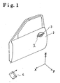
- Fig. 1 is a perspective view of a vehicle door where an antenna device of the present invention is installed;
- Fig. 2 is a perspective view of the antenna device according to a first embodiment of the present invention;
- Fig. 3a is an explanatory view showing how coils are wound according to the first embodiment of the present invention;
- Fig. 3b is a view of an equivalent circuit of the antenna device shown in Fig. 3a;
- Fig. 4 is a perspective view of the antenna device according to a second embodiment of the present invention;
- Fig. 5a is an explanatory view showing how the coils are wound according to the second embodiment of the present invention;
- Fig. 5b is a view of an equivalent circuit of the antenna device shown in Fig. 5a;
- Fig. 6 is a perspective view of a conventional antenna device;
- Fig. 7 is a cross-sectional view of the conventional antenna device.
-
- Embodiments of the present invention will be explained referring to accompanying drawings.
- A
door handle 3 for opening avehicle door 2 relative to a vehicle body (not shown) is provided outside of thevehicle door 2 as shown in Fig. 1. Thedoor handle 3 expands approximately in z-x plane and is opened by thedoor handle 3 to be pulled in an outside direction of the vehicle (y-direction in Fig. 1) so that a lock mechanism (not shown) provided inside of thevehicle door 2 is activated. An antenna device 1 provided inside of thedoor handle 3 generates a magnetic field component within a predetermined area and communicates with a portable device 4 called a remote control. The antenna device 1 is therefore used to determine whether a vehicle user carrying the portable device 4 is close to or away from the vehicle. The vehicle is then equipped with a system for allowing or prohibiting the lock mechanism to be activated (smart entry system) in accordance with a status whether the user is close to the vehicle or not. - The antenna device 1 having a biaxial structure will be explained referring to Figs. 2,3 as a first embodiment of the present invention.
- The antenna device 1 has the biaxial structure as provided with a
first antenna 11 and asecond antenna 12. An antenna ANT consists of thefirst antenna 11 and thesecond antenna 12. Thefirst antenna 11 is formed with afirst coil 14 wound around a rectangularprism ferrite core 13 in a direction perpendicular to a longitudinal direction of theferrite core 13 and a first resonant capacitor C1 connected between a terminal r and a terminal s shown in Fig. 2. The first resonant capacitor C1 is provided so that thefirst antenna 11 is resonated in parallel by a frequency f used for communication with the portable device 4. Theferrite core 13 is arranged so that the longitudinal direction thereof corresponds to x-direction as shown in Fig. 2. That is, the axial direction of thefirst coil 14 is provided in parallel to thevehicle door 2 and thefirst coil 14 is wound so as to expand in x-y plane. Theferrite core 13 is made of a material such as manganese-zinc and nickel-zinc for increasing the antenna efficiency. Theferrite core 13 can be in a round prism shape. - The
second antenna 12 is formed with asecond coil 17 wound around a bobbin 16 (shown in Fig. 3) provided outside of theferrite core 13, alink coil 18 which is constituted by one end portion of thesecond coil 17 wound a predetermined number of times around theferrite core 13, and a second resonant capacitor C2 connected between a terminal p and a terminal q shown in Fig. 3. An oscillator OS and the second resonant capacitor C2 are connected to each other in series between the terminal p and the terminal q. Thebobbin 16 is of an annular shape extending in the longitudinal direction of theferrite core 13. That is, thesecond coil 17 is wound in the longitudinal direction of theferrite core 13, which is a direction perpendicular to a winding direction of thefirst coil 14. The winding direction of thelink coil 18 is same as that of thefirst coil 14. Thesecond coil 17 is arranged so that a predetermined clearance is defined with thefirst coil 14 of thefirst antenna 11. Theferrite core 13 is shared between thefirst coil 14 and thesecond coil 17 for winding. Thebobbin 16 is made of an insulative resin such as ABS resin and polycarbonate resin. - Figs. 3a, 3b are views for explaining a structure of the antenna device 1 more in detail. Fig. 3a shows how the
first coil 14 of thefirst antenna 11, thesecond coil 17 and thelink coil 18 of thesecond antenna 12 are wound. Fig. 3b is an equivalent circuit of the antenna device 1 shown in Fig. 3a. L1, L21, and L22 in Fig. 3b are inductances of thefirst coil 14, thesecond coil 17, and thelink coil 18 respectively. - As shown in Fig. 3a, the
second antenna 12 is formed with a series resonant circuit (second resonant circuit), which is constituted by a series connection of thesecond coil 17, thelink coil 18, and the second resonant capacitor C2. In addition, thefirst antenna 11 is formed with a parallel resonant circuit (first resonant circuit), which is constituted by a parallel connection of thefirst coil 14 and the first resonant capacitor C1. A coupling degree between thefirst antenna 11 and thesecond antenna 12 can be controlled by adjusting a number of turns of thelink coil 18. The second resonant capacitor C2 is set to be resonated in series with a frequency used by the oscillator OS and also the first resonant capacitor C1 is set to be resonated in parallel with the frequency used by the oscillator OS. - Operation of the antenna device 1 will be explained as follows.
- When the oscillator OS of the
second antenna 12 is set into oscillation, thefirst coil 14 of thefirst antenna 11 is excited via thelink coil 18 of thesecond antenna 12. A current is then supplied to thefirst coil 14. A magnetic field Hx in x-direction (first magnetic field component) is generated by thelink coil 18 and thefirst coil 14 as shown in Fig. 2. At the same time, when the oscillator OS is set into oscillation, a magnetic field Hz in z- direction (second magnetic field component) is generated by thesecond coil 17 of thesecond antenna 12. By referring to Fig. 1, the magnetic field Hx is generated in parallel to thevehicle door 2. In addition, the magnetic field Hz is generated in parallel to thevehicle door 2 and also perpendicular to the magnetic field Hx. That is, both magnetic fields Hx and Hz are generated in a direction different from a perpendicular direction to the vehicle door 2 (y-direction). A cancellation effect by thevehicle door 2 of the conductive board is less on the magnetic field component. Thus, the magnetic fields Hx and Hz can be provided with a required strength of the magnetic field component. In addition, the magnetic fields Hx and Hz cross at right angles to each other so that a range of the magnetic field component generated by the antenna device 1 becomes larger. - The antenna of the portable device 4 mentioned above is desirably provided with one-axis structure as a matter of miniaturization. It is thus very important that the range of the magnetic field component can be set larger and the required strength of the magnetic field is secured as in the present embodiment of the antenna device 1. The magnetic field Hz is generated in a vertical direction of the vehicle, i.e., a direction perpendicular to y-direction according to the embodiment of the present invention. However, the magnetic field Hz is not limited to be perpendicular to y-direction. That is, the magnetic field Hz can be generated in a direction with a predetermined angle more than 0 degree relative to y-direction. To acquire the direction of the magnetic field Hz with the predetermined angle, the angle of the
second coil 17 relative to thevehicle door 2 can be adjusted. - The antenna device 1 having a triaxial structure will be explained referring to Figs. 4,5 as a second embodiment of the present invention.
- The antenna device 1 has a triaxial structure as provided with a
third antenna 31, afourth antenna 32 and afifth antenna 33. The antenna ANT consists of thethird antenna 31, thefourth antenna 32 and thefifth antenna 33. Thethird antenna 31 is formed with athird coil 34 wound around the rectangularprism ferrite core 13 in the direction perpendicular to the longitudinal direction of theferrite core 13, and a third resonant capacitor C3 connected between the terminal r and the terminal s shown in Fig. 5. The third resonant capacitor C3 is provided so that thethird antenna 31 is resonated in parallel to the frequency f used for communication with the portable device 4. Theferrite core 13 is arranged so that the longitudinal direction thereof corresponds to x-direction as shown in Fig. 4. That is, an axial direction of thethird coil 34 is provided in parallel to thevehicle door 2 and thethird coil 34 is wound so as to expand in x-y plane. - The
fourth antenna 32 is formed with afourth coil 37 wound around a bobbin 36 (shown in Fig. 5) provided outside of theferrite core 13, alink coil 38 which is constituted by one end portion of thefourth coil 37 wound a predetermined number of times around theferrite core 13, and a fourth resonant capacitor C4 connected between the terminal p and the terminal q shown in Fig. 5. The oscillator OS and the fourth resonant capacitor C4 are connected to each other in series between the terminal p and the terminal q. Thebobbin 36 is of an annular shape extending in the longitudinal direction of theferrite core 13. The axial direction of thefourth coil 37 is not set in a direction perpendicular to z-x plane or not parallel to y-direction. Specifically, the axial direction of thefourth coil 37 is set in a direction deviating from a positive y-direction with a predetermined angle (other than 0 degree) in y-z plane as shown in Fig. 4. In addition, the axial direction of thefourth coil 37 is set to be only rotated in y-z plane and thus still perpendicular to the axial direction of thethird coil 34 of thethird antenna 31. The winding direction of thelink coil 38 is same as that of thethird coil 34. Thefourth coil 37 is provided so that a predetermined clearance is defined with thethird coil 34 of thethird antenna 31. Theferrite core 13 is shared between thefourth coil 37 and thethird coil 34 for winding. - The
fifth antenna 33 is formed with afifth coil 39 wound around theferrite core 13 directly in the longitudinal direction of theferrite core 13, which is a winding direction of thefifth coil 39. That is, thefifth coil 39 is wound inside of thethird coil 34 of thethird antenna 31, thefourth coil 37 and thelink coil 38 of thefourth antenna 32. The axial direction of thefifth coil 39 is perpendicular to that of thethird coil 34. According to the present embodiment, a copper foil ribbon is used for thefifth coil 39. - Fig. 5a, 5b are views for explaining the structure of the antenna device 1 more in detail. Fig. 5a shows how the
third coil 34 of thethird antenna 31, thefourth coil 37 and thelink coil 38 of thefourth antenna 32, and thefifth coil 39 of thefifth antenna 33 are wound. Fig. 5b is an equivalent circuit of the antenna device 1 shown in Fig. 5a. L3, L41, L42 and L5 in Fig. 5b are inductances of thethird coil 34, thefourth coil 37, thelink coil 38 and thefifth coil 39 respectively. - The
fourth antenna 32 is formed with a series resonant circuit (fourth resonance circuit), which is constituted by a series connection of thefourth coil 37, thelink coil 38, and the fourth resonant capacitor C4. In addition, thethird antenna 31 is formed with a parallel resonant circuit (third resonant circuit), which is constituted by a parallel connection of thethird coil 34 and the third resonant capacitor C3. A coupling degree between thethird antenna 31 and thefourth antenna 32 can be controlled by adjusting a number of turns of thelink coil 38. - A coupling degree among the
fifth antenna 33, thethird antenna 31, and thefourth antenna 32 can be controlled by a winding position of thefifth coil 39 at theferrite core 13 and a number of turns of thefifth coil 39. The coupling degree is varied according to a position of thefifth coil 39 in z-direction relative to theferrite core 13. Thefifth coil 39 is directly wound around theferrite core 13 so that a required L3 value can be obtained by a several turns according to the present embodiment. - The operation of the antenna device 1 will be explained as follows.
- When the oscillator OS of the
fourth antenna 32 is set into oscillation, thethird coil 34 of thethird antenna 31 is excited via thelink coil 38. The current is then supplied to thethird coil 34. The magnetic field Hx in x-direction (third magnetic field component) is generated by thelink coil 38 and thethird coil 34 as shown in Fig. 4. At the same time, when the oscillator OS is set into oscillation, the magnetic field Hy (fourth magnetic field component) is generated in a direction deviating from the positive y-direction with the angle in y-z plane. A magnetic field Hz (fifth magnetic field component) in z-direction is generated by thefifth coil 39. By referring to the Fig. 1, when theferrite core 13 is provided in parallel to thevehicle door 2, the magnetic field Hx is generated in parallel to thevehicle door 2. In addition, the magnetic field Hz is generated in parallel to thevehicle door 2 and also perpendicular to the magnetic field Hx. The magnetic field Hy is generated in a direction deviating from a direction perpendicular to thevehicle door 2 with the angle (downward direction in Fig. 4). That is, each magnetic field Hx, Hy, or Hz is generated in a direction different from the direction perpendicular to the vehicle door 2 (y-direction). Thus, a cancellation effect by thevehicle door 2 of the conductive board is less on the magnetic field component. The magnetic fields Hx, Hy and Hz can be provided with the required strength of the magnetic field components. The magnetic fields Hy and Hz are provided in a plane perpendicular to the magnetic field Hx so that a range of the magnetic field component generated from the antenna device 1 becomes larger. According to the present embodiment, the antenna obtains the triaxial structure so that the strength of the magnetic field component can be more assured than the antenna with the biaxial structure. The communication of the antenna with the portable device 4 becomes more efficient accordingly. The value can be negative according to the present embodiment, i.e., the direction of the magnetic field Hy can be set inclined to z-direction. To acquire the predetermined angle of , an angle of thebobbin 36 relative to theferrite core 13 can be adjusted. - According to the present invention, the magnetic field component is generated by the antenna in the direction different from the perpendicular direction to the vehicle door. Thus, the magnetic field component generated by the vehicle door, which is generated in the direction opposite to that of the magnetic field component, is prevented.
That is, the magnetic field component generated by the antenna is not cancelled by the vehicle door so that the required strength of the magnetic field component can be assured. - The magnetic field components with plural axes generated by the antenna cross at right angles to each other so that the range of the magnetic field components generated by the antenna becomes larger.
- The principles, preferred embodiment and mode of operation of the present invention have been described in the foregoing specification. However, the invention which is intended to be protected is not to be construed as limited to the particular embodiments disclosed. Further, the embodiments described herein are to be regarded as illustrative rather than restrictive. Variations and changes may be made by others, and equivalents employed, without departing from the sprit of the present invention. Accordingly, it is expressly intended that all such variations, changes and equivalents which fall within the spirit and scope of the present invention as defined in the claims, be embraced thereby.
- An antenna device includes a door handle provided inside of a vehicle door for opening the vehicle door, and an antenna provided inside of the door handle and generating a magnetic field component in a direction different from a perpendicular direction to an outer surface of the vehicle door.
Claims (8)
- An antenna device comprising:a door handle provided inside of a vehicle door for opening the vehicle door; andan antenna provided inside of the door handle and generating a magnetic field component in a direction different from a perpendicular direction to an outer surface of the vehicle door.
- An antenna device according to claim 1, wherein:the antenna includes a first antenna for generating a first magnetic field component and a second antenna for generating a second magnetic field component, and wherein the first magnetic field component is generated in approximately parallel to the outer surface of the vehicle door and the second magnetic field component is generated perpendicular to the first magnetic field component.
- An antenna device according to claim 2, wherein:the first antenna includes a first resonant circuit having a first coil which axial direction is in parallel to the outer surface of the vehicle door and a first resonant capacitor connected to the first coil, and the second antenna includes a second resonant circuit having a second coil which axial direction is perpendicular to the axial direction of the first coil and provided outside of the first antenna, a link coil connected to the second coil and wound in the same direction as that of the first coil, and a second resonant capacitor connected to the link coil.
- An antenna device according to claim 2, wherein:the antenna includes a third antenna for generating a third magnetic field component, a fourth antenna for generating a fourth magnetic field component, and a fifth antenna for generating a fifth magnetic field component, and wherein the third magnetic field component is generated in approximately parallel to the outer surface of the vehicle door, the fourth magnetic field component is generated perpendicular to the third magnetic field component, and the fifth magnetic field component is generated in approximately parallel to the outer surface of the vehicle door and also perpendicular to the third magnetic field component.
- An antenna device according to claim 4, wherein:the third antenna includes a third resonant circuit having a third coil which axial direction is in parallel to the outer surface of the vehicle door and a third resonant capacitor connected to the third coil, the fourth antenna includes a fourth resonant circuit having a fourth coil which axial direction is perpendicular to the axial direction of the third coil and provided outside of the third antenna, a link coil connected to the fourth coil and wound in the same direction as that of the third coil, and a fourth resonant capacitor connected to the link coil, and the fifth antenna includes a fifth resonant circuit having a fifth coil provided inside of the third antenna and the fourth antenna and which axial direction is in parallel to the outer surface of the vehicle door and also perpendicular to the axial direction of the third coil.
- An antenna device according to claim 3, wherein:the first resonant circuit is a parallel resonant circuit by a parallel connection of the first coil and the first resonant capacitor and the second resonant circuit is a series resonant circuit by a series connection of the second coil, the link coil, and the second resonant capacitor.
- An antenna device according to claim 5, wherein:the third resonant circuit is a parallel resonant circuit by a parallel connection of the third coil and the third resonant capacitor, and the fourth resonant circuit is a series resonant circuit by a series connection of the fourth coil, the link coil, and the fourth resonant capacitor.
- An antenna device according to claim 4, wherein:the fourth magnetic field component is generated in a direction deviating from a perpendicular direction to the vehicle door with a predetermined angle.
Applications Claiming Priority (2)
| Application Number | Priority Date | Filing Date | Title |
|---|---|---|---|
| JP2001363406 | 2001-11-28 | ||
| JP2001363406A JP3882595B2 (en) | 2001-11-28 | 2001-11-28 | Antenna device |
Publications (2)
| Publication Number | Publication Date |
|---|---|
| EP1317016A1 true EP1317016A1 (en) | 2003-06-04 |
| EP1317016B1 EP1317016B1 (en) | 2013-03-13 |
Family
ID=19173752
Family Applications (1)
| Application Number | Title | Priority Date | Filing Date |
|---|---|---|---|
| EP20020026523 Expired - Fee Related EP1317016B1 (en) | 2001-11-28 | 2002-11-27 | Car door handle antenna for keyless system |
Country Status (3)
| Country | Link |
|---|---|
| US (1) | US6795032B2 (en) |
| EP (1) | EP1317016B1 (en) |
| JP (1) | JP3882595B2 (en) |
Cited By (7)
| Publication number | Priority date | Publication date | Assignee | Title |
|---|---|---|---|---|
| WO2005088560A1 (en) * | 2004-03-11 | 2005-09-22 | Marquardt Gmbh | Inductive component, especially for an electronic key |
| EP1980024A1 (en) * | 2007-01-29 | 2008-10-15 | Kutta Consulting, Inc. | Omnidirectional antenna system |
| US8725188B1 (en) | 2007-07-20 | 2014-05-13 | Kutta Technologies, Inc. | Enclosed space communication systems and related methods |
| DE102013104059A1 (en) * | 2013-04-22 | 2014-10-23 | Infineon Technologies Ag | Antenna arrangement, communication device and antenna structure |
| CN106537408A (en) * | 2014-07-31 | 2017-03-22 | 法国大陆汽车公司 | Device for communication by magnetic coupling |
| EP3327864B1 (en) * | 2016-01-22 | 2019-11-27 | Nippon Telegraph and Telephone Corporation | Loop antenna |
| CN111628293A (en) * | 2019-02-28 | 2020-09-04 | 胜美达电机(香港)有限公司 | Antenna device and manufacturing method thereof |
Families Citing this family (24)
| Publication number | Priority date | Publication date | Assignee | Title |
|---|---|---|---|---|
| DE10125080A1 (en) * | 2001-05-23 | 2002-12-19 | Pemetzrieder Neosid | Inductive electrical component, in particular ferrite antenna, and method for producing and adjusting the same |
| ATE377530T1 (en) * | 2001-10-01 | 2007-11-15 | Donnelly Corp | VEHICLE HANDLE ARRANGEMENT WITH ANTENNA |
| JP2004239008A (en) * | 2003-02-07 | 2004-08-26 | Furukawa Electric Co Ltd:The | Outside handle device and connector used for it |
| US7209090B2 (en) * | 2003-06-16 | 2007-04-24 | Sensormatic Electronics Corporation | High efficiency core antenna and construction method |
| JP4152845B2 (en) * | 2003-09-22 | 2008-09-17 | 株式会社アルファ | ANTENNA DEVICE AND AUTOMOBILE DOOR OUTSIDE HANDLE DEVICE HAVING THE ANTENNA DEVICE |
| JP3696866B2 (en) * | 2003-10-20 | 2005-09-21 | 株式会社アルファ | Door opener |
| US7407203B2 (en) * | 2004-08-18 | 2008-08-05 | Donnelly Corporation | Vehicle door handle |
| EP1795860B1 (en) * | 2004-09-28 | 2012-11-14 | Aisin Seiki Kabushiki Kaisha | Antenna assembly and door handle unit |
| JP2008079118A (en) * | 2006-09-22 | 2008-04-03 | Alpha Corp | Vehicle antenna apparatus |
| CN101622756A (en) * | 2007-03-09 | 2010-01-06 | 株式会社村田制作所 | Antenna coil for mounting on circuit board |
| US20100088855A1 (en) * | 2008-10-14 | 2010-04-15 | Magna Mirrors Of America, Inc. | Vehicle door handle assembly |
| JP5527218B2 (en) * | 2008-12-19 | 2014-06-18 | 日立金属株式会社 | Resonant receiving antenna and receiving apparatus |
| US8786401B2 (en) | 2009-12-23 | 2014-07-22 | Magna Mirrors Of America, Inc. | Extendable flush door handle for vehicle |
| JP5639606B2 (en) * | 2012-02-27 | 2014-12-10 | 三智商事株式会社 | Wireless IC tag |
| US9620858B2 (en) * | 2013-03-18 | 2017-04-11 | Alfano Robert R | Compact electromagnetic-radiation antenna |
| DE202013005125U1 (en) * | 2013-06-04 | 2014-09-05 | Hugo Vogelsang Maschinenbau Gmbh | Device for electrical disintegration of cell aggregates |
| US9484626B2 (en) | 2013-06-10 | 2016-11-01 | Magna Mirrors Of America, Inc. | Vehicle door handle assembly with antenna circuit |
| US10461396B2 (en) * | 2015-04-03 | 2019-10-29 | Fit Pay, Inc. | System and method for low-power close-proximity communications and energy transfer using a miniature multi-purpose antenna |
| JP6701907B2 (en) * | 2016-04-13 | 2020-05-27 | スミダコーポレーション株式会社 | Antenna device and method of manufacturing antenna device |
| WO2018216458A1 (en) * | 2017-05-26 | 2018-11-29 | 株式会社村田製作所 | Antenna coil |
| DE102017008340A1 (en) * | 2017-09-05 | 2019-03-07 | Huf Hülsbeck & Fürst Gmbh & Co. Kg | Motor vehicle door handle assembly with embedded electronics |
| ES2875576T3 (en) * | 2017-10-23 | 2021-11-10 | Premo Sa | Antenna for low frequency communication inside a vehicle environment and low frequency communication system |
| CN111335757B (en) | 2018-12-19 | 2021-10-15 | 麦格纳覆盖件有限公司 | Vehicle door actuating system |
| US11764462B2 (en) * | 2020-08-11 | 2023-09-19 | BCS Access Systems US, LLC | Vehicle door handle |
Citations (6)
| Publication number | Priority date | Publication date | Assignee | Title |
|---|---|---|---|---|
| US5134392A (en) * | 1987-06-16 | 1992-07-28 | Nissan Motor Company, Limited | Keyless entry system for locking and unlocking a vehicular lock device by a pocket portable radio signal transmitter and antenna arrangement therefor |
| JPH10163746A (en) * | 1996-11-29 | 1998-06-19 | Nissan Motor Co Ltd | Built-in antenna for keyless entry system |
| EP0943764A1 (en) * | 1998-03-16 | 1999-09-22 | Robert Bosch Gmbh | Door handle and transponder system |
| EP1083280A2 (en) * | 1999-09-10 | 2001-03-14 | Kiekert Aktiengesellschaft | Keyless actuating and/or locking device, particularly for vehicles |
| JP2002252521A (en) * | 2001-02-23 | 2002-09-06 | Aisin Seiki Co Ltd | Loop antenna device |
| WO2002095873A2 (en) * | 2001-05-23 | 2002-11-28 | Neosid Pemetzrieder Gmbh & Co. Kg | Ferrite antenna |
Family Cites Families (4)
| Publication number | Priority date | Publication date | Assignee | Title |
|---|---|---|---|---|
| DE19861116C2 (en) * | 1998-07-17 | 2002-05-02 | Siemens Ag | Access control device for a motor vehicle and method for adjusting the sensitivity of the access control device |
| JP3648396B2 (en) * | 1998-12-02 | 2005-05-18 | トヨタ自動車株式会社 | Vehicle door handle |
| JP3562476B2 (en) | 2000-02-18 | 2004-09-08 | アイシン精機株式会社 | Loop antenna device |
| JP3855253B2 (en) * | 2000-06-13 | 2006-12-06 | アイシン精機株式会社 | Bar antenna and manufacturing method thereof |
-
2001
- 2001-11-28 JP JP2001363406A patent/JP3882595B2/en not_active Expired - Fee Related
-
2002
- 2002-11-27 EP EP20020026523 patent/EP1317016B1/en not_active Expired - Fee Related
- 2002-11-27 US US10/304,916 patent/US6795032B2/en not_active Expired - Lifetime
Patent Citations (7)
| Publication number | Priority date | Publication date | Assignee | Title |
|---|---|---|---|---|
| US5134392A (en) * | 1987-06-16 | 1992-07-28 | Nissan Motor Company, Limited | Keyless entry system for locking and unlocking a vehicular lock device by a pocket portable radio signal transmitter and antenna arrangement therefor |
| JPH10163746A (en) * | 1996-11-29 | 1998-06-19 | Nissan Motor Co Ltd | Built-in antenna for keyless entry system |
| EP0943764A1 (en) * | 1998-03-16 | 1999-09-22 | Robert Bosch Gmbh | Door handle and transponder system |
| EP1083280A2 (en) * | 1999-09-10 | 2001-03-14 | Kiekert Aktiengesellschaft | Keyless actuating and/or locking device, particularly for vehicles |
| JP2002252521A (en) * | 2001-02-23 | 2002-09-06 | Aisin Seiki Co Ltd | Loop antenna device |
| DE10207944A1 (en) * | 2001-02-23 | 2002-11-21 | Aisin Seiki | Loop antenna device |
| WO2002095873A2 (en) * | 2001-05-23 | 2002-11-28 | Neosid Pemetzrieder Gmbh & Co. Kg | Ferrite antenna |
Non-Patent Citations (2)
| Title |
|---|
| PATENT ABSTRACTS OF JAPAN vol. 1998, no. 11 30 September 1998 (1998-09-30) * |
| PATENT ABSTRACTS OF JAPAN vol. 2003, no. 01 14 January 2003 (2003-01-14) * |
Cited By (11)
| Publication number | Priority date | Publication date | Assignee | Title |
|---|---|---|---|---|
| WO2005088560A1 (en) * | 2004-03-11 | 2005-09-22 | Marquardt Gmbh | Inductive component, especially for an electronic key |
| EP1980024A1 (en) * | 2007-01-29 | 2008-10-15 | Kutta Consulting, Inc. | Omnidirectional antenna system |
| EP1980024A4 (en) * | 2007-01-29 | 2009-09-02 | Kutta Consulting Inc | Omnidirectional antenna system |
| US8725188B1 (en) | 2007-07-20 | 2014-05-13 | Kutta Technologies, Inc. | Enclosed space communication systems and related methods |
| DE102013104059A1 (en) * | 2013-04-22 | 2014-10-23 | Infineon Technologies Ag | Antenna arrangement, communication device and antenna structure |
| US10096902B2 (en) | 2013-04-22 | 2018-10-09 | Infineon Technologies Ag | Antenna arrangement, communication appliance and antenna structure |
| CN106537408A (en) * | 2014-07-31 | 2017-03-22 | 法国大陆汽车公司 | Device for communication by magnetic coupling |
| CN106537408B (en) * | 2014-07-31 | 2019-07-12 | 法国大陆汽车公司 | Pass through magnetic-coupled communication equipment |
| EP3327864B1 (en) * | 2016-01-22 | 2019-11-27 | Nippon Telegraph and Telephone Corporation | Loop antenna |
| CN111628293A (en) * | 2019-02-28 | 2020-09-04 | 胜美达电机(香港)有限公司 | Antenna device and manufacturing method thereof |
| CN111628293B (en) * | 2019-02-28 | 2024-03-19 | 胜美达电机(香港)有限公司 | Antenna device and manufacturing method thereof |
Also Published As
| Publication number | Publication date |
|---|---|
| JP3882595B2 (en) | 2007-02-21 |
| EP1317016B1 (en) | 2013-03-13 |
| US20030122725A1 (en) | 2003-07-03 |
| US6795032B2 (en) | 2004-09-21 |
| JP2003163525A (en) | 2003-06-06 |
Similar Documents
| Publication | Publication Date | Title |
|---|---|---|
| US6795032B2 (en) | Antenna device | |
| JP4254859B2 (en) | Antenna device and communication system using the same | |
| US6163305A (en) | Loop antenna device | |
| US7095381B2 (en) | Antenna coil | |
| KR100813347B1 (en) | Antenna coil, resonant antenna having antenna coil, and card type wireless device having resonant antenna | |
| US6664936B2 (en) | Loop antenna device | |
| US9490537B2 (en) | Antenna device and electronic apparatus | |
| EP0715043B1 (en) | A key having an air coil antenna and a method of construction | |
| US7365697B2 (en) | Card type wireless device, antenna coil, and method for manufacturing communication module | |
| US7699231B2 (en) | Reader/writer and mobile communication apparatus | |
| US6965352B2 (en) | Antenna device for vehicles and vehicle antenna system and communication system using the antenna device | |
| KR101978694B1 (en) | 3-axis type Low Frequency Antenna Module and keyless entry system including the same | |
| JP3562476B2 (en) | Loop antenna device | |
| US20070115192A1 (en) | Key fob having LF single dimension tranceive antenna and two-dimension receive antenna | |
| US20020113747A1 (en) | Transmitter and receiver coil | |
| JP3941323B2 (en) | Loop antenna device | |
| JP4419687B2 (en) | Antenna device and communication system using the same | |
| JP2004153649A (en) | Coil antenna for reception | |
| KR20180036349A (en) | Low Frequency Antenna Module and keyless entry system including the same | |
| JP3546623B2 (en) | Electromagnetic induction type automatic response device | |
| JP2004350176A (en) | Antenna and communication system using same | |
| JP2004364231A (en) | Antenna device for vehicle and communication system using the same | |
| JP2004363638A (en) | Vehicle antenna system and communication system employing the same |
Legal Events
| Date | Code | Title | Description |
|---|---|---|---|
| PUAI | Public reference made under article 153(3) epc to a published international application that has entered the european phase |
Free format text: ORIGINAL CODE: 0009012 |
|
| AK | Designated contracting states |
Designated state(s): AT BE BG CH CY CZ DE DK EE ES FI FR GB GR IE IT LI LU MC NL PT SE SK TR |
|
| AX | Request for extension of the european patent |
Extension state: AL LT LV MK RO SI |
|
| 17P | Request for examination filed |
Effective date: 20030919 |
|
| AKX | Designation fees paid |
Designated state(s): DE FR GB |
|
| 17Q | First examination report despatched |
Effective date: 20040614 |
|
| GRAP | Despatch of communication of intention to grant a patent |
Free format text: ORIGINAL CODE: EPIDOSNIGR1 |
|
| GRAS | Grant fee paid |
Free format text: ORIGINAL CODE: EPIDOSNIGR3 |
|
| GRAA | (expected) grant |
Free format text: ORIGINAL CODE: 0009210 |
|
| AK | Designated contracting states |
Kind code of ref document: B1 Designated state(s): DE FR GB |
|
| REG | Reference to a national code |
Ref country code: GB Ref legal event code: FG4D |
|
| REG | Reference to a national code |
Ref country code: DE Ref legal event code: R096 Ref document number: 60244630 Country of ref document: DE Effective date: 20130508 |
|
| REG | Reference to a national code |
Ref country code: DE Ref legal event code: R084 Ref document number: 60244630 Country of ref document: DE Effective date: 20130820 |
|
| PLBE | No opposition filed within time limit |
Free format text: ORIGINAL CODE: 0009261 |
|
| STAA | Information on the status of an ep patent application or granted ep patent |
Free format text: STATUS: NO OPPOSITION FILED WITHIN TIME LIMIT |
|
| 26N | No opposition filed |
Effective date: 20131216 |
|
| REG | Reference to a national code |
Ref country code: DE Ref legal event code: R097 Ref document number: 60244630 Country of ref document: DE Effective date: 20131216 |
|
| GBPC | Gb: european patent ceased through non-payment of renewal fee |
Effective date: 20131127 |
|
| PG25 | Lapsed in a contracting state [announced via postgrant information from national office to epo] |
Ref country code: GB Free format text: LAPSE BECAUSE OF NON-PAYMENT OF DUE FEES Effective date: 20131127 |
|
| REG | Reference to a national code |
Ref country code: FR Ref legal event code: PLFP Year of fee payment: 14 |
|
| REG | Reference to a national code |
Ref country code: FR Ref legal event code: PLFP Year of fee payment: 15 |
|
| REG | Reference to a national code |
Ref country code: FR Ref legal event code: PLFP Year of fee payment: 16 |
|
| REG | Reference to a national code |
Ref country code: FR Ref legal event code: PLFP Year of fee payment: 17 |
|
| PGFP | Annual fee paid to national office [announced via postgrant information from national office to epo] |
Ref country code: DE Payment date: 20181113 Year of fee payment: 17 |
|
| PGFP | Annual fee paid to national office [announced via postgrant information from national office to epo] |
Ref country code: FR Payment date: 20181011 Year of fee payment: 17 |
|
| REG | Reference to a national code |
Ref country code: DE Ref legal event code: R119 Ref document number: 60244630 Country of ref document: DE |
|
| PG25 | Lapsed in a contracting state [announced via postgrant information from national office to epo] |
Ref country code: FR Free format text: LAPSE BECAUSE OF NON-PAYMENT OF DUE FEES Effective date: 20191130 Ref country code: DE Free format text: LAPSE BECAUSE OF NON-PAYMENT OF DUE FEES Effective date: 20200603 |