EP1316862A2 - Elektromechanische Schaltuhr - Google Patents
Elektromechanische Schaltuhr Download PDFInfo
- Publication number
- EP1316862A2 EP1316862A2 EP02026601A EP02026601A EP1316862A2 EP 1316862 A2 EP1316862 A2 EP 1316862A2 EP 02026601 A EP02026601 A EP 02026601A EP 02026601 A EP02026601 A EP 02026601A EP 1316862 A2 EP1316862 A2 EP 1316862A2
- Authority
- EP
- European Patent Office
- Prior art keywords
- drive
- sensor
- time
- timer according
- electromechanical timer
- Prior art date
- Legal status (The legal status is an assumption and is not a legal conclusion. Google has not performed a legal analysis and makes no representation as to the accuracy of the status listed.)
- Granted
Links
- 238000000034 method Methods 0.000 claims abstract description 21
- 230000005291 magnetic effect Effects 0.000 claims description 16
- 230000005540 biological transmission Effects 0.000 claims description 10
- 230000002441 reversible effect Effects 0.000 claims description 9
- 230000008859 change Effects 0.000 claims description 8
- 230000000737 periodic effect Effects 0.000 claims description 8
- 230000008569 process Effects 0.000 claims description 4
- 238000001514 detection method Methods 0.000 claims description 3
- 230000003287 optical effect Effects 0.000 claims description 3
- 239000013078 crystal Substances 0.000 claims description 2
- 230000001052 transient effect Effects 0.000 claims 2
- 230000004913 activation Effects 0.000 claims 1
- 230000001934 delay Effects 0.000 claims 1
- 238000010586 diagram Methods 0.000 description 6
- 230000006870 function Effects 0.000 description 6
- 230000004888 barrier function Effects 0.000 description 5
- 239000010453 quartz Substances 0.000 description 5
- VYPSYNLAJGMNEJ-UHFFFAOYSA-N silicon dioxide Inorganic materials O=[Si]=O VYPSYNLAJGMNEJ-UHFFFAOYSA-N 0.000 description 5
- 230000001360 synchronised effect Effects 0.000 description 5
- 238000013519 translation Methods 0.000 description 4
- 230000008901 benefit Effects 0.000 description 3
- 230000001419 dependent effect Effects 0.000 description 3
- 230000007257 malfunction Effects 0.000 description 3
- 230000003442 weekly effect Effects 0.000 description 3
- 238000013016 damping Methods 0.000 description 2
- 238000005265 energy consumption Methods 0.000 description 2
- 230000004907 flux Effects 0.000 description 2
- 230000006698 induction Effects 0.000 description 2
- 230000007246 mechanism Effects 0.000 description 2
- 230000011514 reflex Effects 0.000 description 2
- 230000015572 biosynthetic process Effects 0.000 description 1
- 238000010276 construction Methods 0.000 description 1
- 238000012937 correction Methods 0.000 description 1
- 230000003111 delayed effect Effects 0.000 description 1
- 238000013461 design Methods 0.000 description 1
- 230000000694 effects Effects 0.000 description 1
- 238000005516 engineering process Methods 0.000 description 1
- 238000011156 evaluation Methods 0.000 description 1
- 230000005294 ferromagnetic effect Effects 0.000 description 1
- 238000009434 installation Methods 0.000 description 1
- 230000003993 interaction Effects 0.000 description 1
- 238000004519 manufacturing process Methods 0.000 description 1
- 238000005259 measurement Methods 0.000 description 1
- 230000009347 mechanical transmission Effects 0.000 description 1
- 238000003825 pressing Methods 0.000 description 1
- 238000011084 recovery Methods 0.000 description 1
- 230000009467 reduction Effects 0.000 description 1
- 238000002310 reflectometry Methods 0.000 description 1
- 230000000284 resting effect Effects 0.000 description 1
- 210000002023 somite Anatomy 0.000 description 1
- 238000012546 transfer Methods 0.000 description 1
- 230000007704 transition Effects 0.000 description 1
- 230000001960 triggered effect Effects 0.000 description 1
Images


Classifications
-
- G—PHYSICS
- G04—HOROLOGY
- G04C—ELECTROMECHANICAL CLOCKS OR WATCHES
- G04C23/00—Clocks with attached or built-in means operating any device at preselected times or after preselected time-intervals
- G04C23/02—Constructional details
- G04C23/12—Electric circuitry
Definitions
- the present invention relates to an electromechanical timer with the features of the preamble of claim 1.
- Electromechanical timers are used almost exclusively single-phase stepper drives (type Lavet) driven synchronously. These drives essentially consist of a drive coil and ferromagnetic flux guide pieces (stator) and from one permanent magnetic rotor, which is either 2-pole diametral or is multipolar laterally magnetized on the circumference. It is a matter of controlled drives, in which the rotor with each Control pulse rotates by a precisely defined step.
- the drive is via a multi-stage gear with the program switching disc rigidly coupled.
- the speed of the program switching disc is through the gear ratio of the transmission and the drive speed certainly. With day time switches, this turns Program switching disc once per 24 hours, at Weekly time switches, the program switching disc rotates 1 time every 7 Days.
- the switching elements on the circumference of the program switching disc are sensed by a switching mechanism.
- the Switching mechanism operated according to the position of the Switching elements an electrical switch.
- Both helical gear and worm gear are common.
- Another disadvantage of this timer is that accuracy the time switch or the change from daylight saving time to Winter time and vice versa is dependent on the radio time signal.
- A has such dependence on a radio time signal for time switches however some disadvantages. So has a timer whose function is from a radio time signal is dependent, and which, for example, in a control cabinet is installed as a result of that in the control cabinet generated electromagnetic interference fields a disturbed reception the time signal emitted by the central time transmitter. As well low-reception cellars can safely receive the Disturb time signal significantly. In such cases, it is flawless Function of the time switch disclosed in the publication no longer guaranteed.
- the invention is therefore based on the object of Document DE 295 05 405 U1 known timer to improve so that on the one hand radio-independent operation is possible, whereby also a proposal for the design of the control is made and malfunctions of the drive are recognized can.
- An electromechanical timer provides the solution to this problem according to claim 1. This is essentially achieved by Use of an electronic control in connection with a forward and possibly backward rotating drive and a sensor.
- Another concern is to propose such a timer, which a quick adjustment of the program disc both forward as well as backwards.
- the speed of the drive is preferably in relation to the mechanical transmission ratio many times higher designed for continuous real time operation of the Time switch is necessary.
- the drive is only for a short Duty cycle activated within a periodic time interval.
- the control unit regulates the duty cycle of the drive. Intermittent operation increases the relatively high speed of the drive electronically geared down.
- the drive is controlled by the electronic control at the beginning of the periodic time interval switched on, the switch-off time is determined by the fact that for the defined time interval of Steps of the drive provided by the controller from the sensor recorded and reported to the electronic control.
- a gear wheel (sensor wheel) is included Provide time-equivalent markings detected by the sensor become.
- the Program switching disc adjusted by one or more steps.
- the The drive is switched off as soon as the sensor uses the Markings recorded the steps specified by the control Has. It is also possible for the sensor to pass the current through the Coil of the drive or the voltage across the coil is then detected from the detected signal to determine whether the drive from the Controller has made the intended number of steps.
- the Duty cycle of the drive is due to its high speed normal clock operation is very short compared to the time interval.
- the means for the adjustment of the program switching disc around the one The drive requires a very large time interval less time than a time interval.
- the signals from the sensor will be fed to a sensor counter.
- a forward only rotating drive can be used for a number Time intervals remain switched off, which is a reset of the clock Correspond to 1 hour.
- the power reserve duration is compared to conventional watches in particular significantly increased by the fact that neither the drive the load switch is still active during a power failure.
- the electronic circuit detects via the network sensor input whether the Mains voltage is available or not.
- Power failure counter started, which records the duration of the power failure.
- the clock is reset to the current time, by switching on the drive until the counter reading of the Sensor counter is the same as the status of the power failure counter. Then both count registers are reset to 0, and the normal clock operation with periodic time intervals executed.
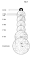
- Fig. 1 shows a spur gear of a conventional quartz day time switch including drive shaft and program disk (toothing not shown).
- the switching disk is driven by a step drive at constant time intervals, both in mains operation and in power reserve operation, as long as the accumulator has enough energy.
- the gear ratios are shown in the table below.
- FIG. 2 shows an electromechanical day timer in the embodiment according to the invention.
- the program switching disc is not driven in the power reserve, but is automatically set to the current time when the power returns.
- the gear ratios are shown in the table below. Number of teeth wheel Number of teeth drive translation factor Average time per 1 revolution Medium speed Drive shaft (continuous operation) 0.1 s 10 / s Drive shaft (intermittent operation) 0 (shaft diameter 2.5 mm) 240 (ratio off: on) 24 s 150 / h 1st wheel 0 (wheel diameter 25 mm) 10 10 4 min 15 / h 2nd wheel 50 10 5 20 min 3 / h 3rd wheel 75 10 7.5 2.5 h 9.6 / d Program switching disc 96 9.6 24 hours 1 / d
- the electronic control unit generates like a typical one electronic clock from the vibrations of an oscillator 23 by means of an electronic multi-stage divider 25 a time-synchronous Clock, preferably with a clock frequency of 1 Hz.
- This clock is used around register 27 for the current time and the current Increment date continuously.
- the content of register 27 for the current time and date can be over a Programming input 24 to the current time and the current date can be set.
- a driver 28 at periodic time intervals is preferred started by the electronic control in minute intervals and switches the drive 10 on.
- the drive 10 is switched off if the transmission sensor 20 using a marking 19, preferably a minute mark, the movement of a Gear wheel (sensor wheel) by a certain angle of rotation preferably corresponds exactly to the adjustment of the clock by 1 minute, reports back to the electronic control.
- the sensor signal is fed to the sensor counter 31.
- the sensor counter 31 has the function of a repeating preselection counter which, when reaching the preselection outputs an output signal and resets the counting register to 0.
- the output signal of the sensor counter 31 acts on the driver 28 and switches off the drive.
- the sensor counter 31 is depending on Operating state of the clock by the control program on a certain area code set. In normal watch operation, this is Area code set to 1.
- An input 33 of the electronic control is switched which is coupled to the shift lever 17 either at logic “1" (Vcc 41) or switched to logic “0" (GND 35).
- An exit 33 ' controls the load relay 38 as a function of this signal Contact life of the load relay 38 can increase the Signal edges of the output 33 'are delayed so that the Switching of the load relay 38 always shortly before a zero crossing the mains voltage. The zero crossings of the mains voltage are detected by the network sensor 34.
- the network sensor 34 starts in the event of a power failure, a power failure counter 32 which records the time intervals - for example minute intervals - the power failure cyclically from 0 counts up to 720 and down again to 0, then again up to 720, etc.
- the power failure counter 32 When the power returns, the power failure counter 32 is stopped.
- the The current counter reading is sent to the sensor counter 31 as a preselection transfer.
- the driver 28 With the next drive pulse in the operating mode forward or put into operation backwards to set the clock.
- the procedure described is an adjustment of the clock after a power failure forward or backward by a maximum of 12 hours.
- the number of Time intervals that the setting process takes are registered and added to the preselection of the sensor counter 31 when the clock is moving forward is adjusted, or subtracted when the clock is adjusted backwards.
- driver 28 is controlled by the controller switched off due to the output signal of the sensor counter 31 and at the same time the control program sets the preselection of the Sensor counter 31 back to 1 and the power failure counter 32 again to 0, which corresponds to normal clock operation.
- the program switch 15 was at Power recovery adjusted according to the duration of the power failure. To at this time the output 33 ′ for the load relay 38 reactivated according to the state of input 33.
- the watch can also be equipped with a drive that only turns in one direction (forward).
- the counts Power failure counter 32 the minutes of the power failure cyclically from 0 to 1439 upwards and then starts again at 0.
- the clock must be at this method after a power failure in the worst case at 23 h 59 minutes can be adjusted.
- a weekly timer works on the same principle. Only the power failure counter 32 works with others Count ranges. If a drive 10 that can be operated forwards / backwards inserted, then the power failure counter 32 counts the minutes of the Power failure cyclically from 0 up to 5040 and back down to 0, then up again to 5040 etc. This ensures that the watch in the worst case by a maximum of 5040 minutes (3.5 days) must be readjusted forward or backward.
- the watch can also be equipped with a drive 10, that only rotates in one direction (forward).
- the counts Power failure counter 32 the minutes of the power failure cyclically from 0 to 10079 upwards and then starts again at 0.
- the clock must be at this method after a power failure in the worst case by 6 d: 23 h: 59 min can be adjusted.
- the region in the summer / winter time selection 26 is selected via two inputs of the electronic control, the changeover rule of which should be taken into account.
- a specific signal pattern is assigned to each region at the inputs. The assignment can look like this, for example. Entrance 1 Entrance 2 region GND GND EUROPE GND Vcc United States Vcc Vcc No changeover function
- In the first changeover register 29 is, for example, the time and the Date of the start of daylight saving time saved.
- the second changeover register 30 is, for example, the time and the Date of the start of winter time saved.
- the clock is also reset by the Driver 28 for a certain number of drive pulses, e.g. 60 Minute impulses, is blocked. In other words, watchmaking works for exactly 1 hour to then resume normal operation.
- the electromechanical timer has at least one mechanical control input 22 via which an adjustment of Time switch forward by pressing the corresponding key becomes.
- a second control input 22 ' is advantageous, the one appropriate adjustment of the time switch allows backwards.
- the sensor pulses are raised accordingly the current time register 27 is added or subtracted.
- the Date register is not affected by this setting process.
- the first gear stage is preferably a friction gear executed. This has the advantage that compared to running noise Helical gear teeth are significantly lower, and that higher Gear ratios are realizable.
- the first gear stage can alternatively also be a worm gear be executed.
- Fig. 3 shows an electromechanical day timer as a simplified Execution according to the invention.
- the program switching disc 15 is in Power reserve not driven, but when the power returns automatically set to the current time.
- Load switch 39 is at Power return active and switches in the clock adjustment phase according to the set program. Based on the in Fig. 3 shown execution are the possibilities and Restrictions are shown with a simplified Version are connected.
- the load relay 38 is by a mechanical load switch 39 replaced, which is controlled directly by the shift lever 17.
- 33 ' In order to there is no input / output 33 in the electronic control, 33 '.
- the components for the electronic are also eliminated Control of the relay. Furthermore, the expense of components significantly reduced in the area of the power supply.
- the embodiment shown in Fig. 4 electromechanical timer this is a Daily time switch, differs from that shown in Fig. 3 Embodiment essentially by the type of sensor 21, which acts on the sensor counter 31 with the sensor signal.
- an electronic sensor 21 provided, essentially by an integrated Comparator circuit is formed by the rotor movement voltage induced in the coil after switching off the drive pulse detected.
- the drive 10 is in the embodiment of FIG.
- the drive 10 is periodically driven by the driver 28 Drive pulses 50 (Fig. 5) of changing polarity driven.
- Single-phase stepper motors behave below a limit frequency type Lavet in the controlled area very stable and perform a defined step per drive pulse 50.
- the next step is only carried out when the rotor 44 in its has finally settled in new resting position, that is, when the Vibration of the rotor 44 as a result of the native damping has subsided. This is shown in more detail with reference to FIG. 5, wherein those shown schematically below the voltage-time diagram Rotor positions each the rest position of the rotor in front of the represents next drive pulse 50.
- the drive pulses 50 are in the form of a rectangular pulse of short duration on the drive coil given.
- the drive pulses generate in the coil 42 of the drive 10 a magnetic field, the permanent magnet rotor 44 of the drive 10 opposite to that of the coil 42 of the drive 10 generated magnetic field is aligned.
- the drive pulse is short and dimensioned so that the rotor 44 from its magnetic Rest position is rotated and after switching off the drive pulse 50th due to its magnetic interaction with the stator dampens into its new rest position offset by 180 °.
- the coil is moved by the movement of the permanently excited rotor 44 42 of the drive 10 from a temporally changing magnetic River interspersed. This changing magnetic flux over time through the coil 42 induces a voltage in the coil, which over the sensor 21 is detected and on the basis of which the movement of the rotor 44 can detect.
- the drive 10 accelerates from standstill until it finally one drive-typical final speed reached at which the mutual induction prevents further energy consumption.
- the final speed is one many times higher than the speed in normal watch operation with periodic drive pulses 50
- Fast adjustment of the clock enables.
- the connections of the coil 42 4, as shown in FIG. 4, with the inputs one in the sensor 21 included comparator circuit connected.
- the Comparator circuit detected after switching off the Drive pulse the zero crossing due to the rotation of the Rotor 44 induced voltage and generates a signal from it, which is fed to the sensor counter 31. Further through the Driver 28 generated drive pulses in quick succession suppressed as soon as the sensor counter 31 for the quick adjustment has registered the necessary number of drive pulses. Drive impulses are then periodically for the normal Clock operation issued by driver 28.
- the quick adjustment backwards also starts at one Standstill of the rotor 44 by applying a drive pulse 54, which when turning or accelerating the rotor 44 in Causes forward direction. Immediately after the start however, the rotational movement in the forward direction becomes one Drive pulse 55 applied with reverse polarity. This Drive pulse 55 causes braking of the forward movement and finally a reversal of the direction of rotation of the rotor 44.
- the duration of the first drive pulse 54 and the second drive pulse 55 each drive-specific and dimensioned so that the rotor 44 after Turn off the second drive pulse 55 due to it kinetic energy the original rest position at the beginning of the Quick adjustment overflowed.
- the rotor 44 accelerates until an end speed typical of the drive is reached, at which the mutual induction and another Prevents energy consumption. This final speed is a multiple higher than the speed in normal watch operation with periodic Drive impulses and thus enables a quick adjustment of the clock backward.
- the movable gear parts are by an inventive Execution usually significantly reduced.
- a execution according to the invention are compared to conventional version only 4 gears instead of 6 Gear wheels needed, although the rotor speed in the Embodiment according to the invention in FIG. 2 by a factor of 20 is higher than in the exemplary embodiment in FIG. 1.
Landscapes
- Physics & Mathematics (AREA)
- General Physics & Mathematics (AREA)
- Electromechanical Clocks (AREA)
- Control Of Transmission Device (AREA)
Abstract
Description
Für einen typischen Antrieb in einer Synchronuhr mit einer Ansteuerfrequenz von f = 50 Hz und einer Polpaarzahl von p = 5 ergibt sich eine Antriebsdrehzahl von n = 10/s.
- Automatische Sommer-/Winterzeit- Umstellung
- Gangreservedauer > 1a
- Einen Quarzoszillator und Frequenzteiler zur Erzeugung eines zeitsynchronen Takts.
- Ein Zeitregister in dem die aktuelle Zeit und das Datum registriert werden, und über einen Programmiereingang einstellbar sind.
- Eingänge zur Auswahl der Sommer-/Winterzeit Region.
- Einen Treiber zur Ansteuerung eines Antriebs.
- Eingänge zur manuellen Vorwärts- und Rückwärtssteuerung des Antriebs um die Schaltuhr auf die entsprechende Ortszeit in einer anderen Zeitzone einzustellen.
- Umstellregister in welchen die Informationen bezüglich der Umstellzeiten und des jeweiligen Umstelldatums für verschiedene Jahre und Regionen (Europa, USA, etc....) dauerhaft gespeichert sind.
- Einen Sensoreingang, der auf einen Sensorzähler wirkt.
- Einen Netzsensoreingang zur Erkennung der Netzspannung und ggf. der Nulldurchgänge.
- Einen Netzausfallzähler in dem die Dauer eines Netzausfalls registriert wird.
- Einen Programmeingang, der in Abhängigkeit des Schaltprogramms die beiden logischen Zustände "0" (GND) oder "1" (Vcc) aufweist.
- Einen Programmausgang, der in Abhängigkeit des Zustands des Programmeingangs das Ein- bzw. Ausschalten eines Lastrelais bewirkt.
- Fig. 1
- ein Stirnradgetriebe einer herkömmlichen Quarz-Tagesschaltuhr (Prinzip Stand der Technik);
- Fig. 2
- eine elektromechanische Schaltuhr in einer erfindungsgemäßen Ausführung, schematisch vereinfachtes Diagramm;
- Fig. 3
- eine elektromechanische Schaltuhr in einer vereinfachten erfindungsgemäßen Ausführung, schematisch vereinfachtes Diagramm;
- Fig. 4
- eine elektromechanische Schaltuhr in einer erfindungsgemäßen Ausführung mit einem elektronischen Sensor;
- Fig. 5
- ein Spannungszeitdiagramm der über die Spule des Antriebs abfallenden Spannung bei normalem Uhrenbetrieb;
- Fig. 6
- ein Spannungszeitdiagramm der über die Spule des Antriebs abfallenden Spannung bei einer Schnellvorstellung vorwärts und
- Fig. 7
- ein Spannungszeitdiagramm der über die Spule des Antriebs abfallenden Spannung bei einer Schnellverstellung rückwärts.
| Zahnzahl Rad | Zahnzahl Trieb | Übersetzungsfaktor | Mittlere Zeit pro 1 Umdrehung | Mittlere Drehzahl | |
| Antrieb | 10 | 2 s | 0,5/s | ||
| 1. Rad | 48 | 10 | 4,8 | 9,6 s | 6,25/min |
| 2. Rad | 50 | 10 | 5 | 48 s | 1,25/min |
| 3. Rad | 50 | 10 | 5 | 4 min | 15/h |
| 4. Rad | 50 | 10 | 5 | 20 min | 3/h |
| 5. Rad | 75 | 10 | 7,5 | 2,5 h | 9,6/d |
| Schaltscheibe | 96 | 9,6 | 24 h | 1/d |
| Zahnzahl Rad | Zahnzahl Trieb | Übersetzungsfaktor | Mittlere Zeit pro 1 Umdrehung | Mittlere Drehzahl | |
| Antriebswelle (Dauerbetrieb) | 0,1 s | 10/s | |||
| Antriebswelle (Intervallbetrieb) | 0 (Wellendurchmesser 2,5 mm) | 240 (Verhältnis Aus:Ein) | 24 s | 150/h | |
| 1. Rad | 0 (Raddurchmesser 25 mm) | 10 | 10 | 4 min | 15/h |
| 2. Rad | 50 | 10 | 5 | 20 min | 3/h |
| 3. Rad | 75 | 10 | 7,5 | 2,5 h | 9,6/d |
| Programm schaltscheibe | 96 | 9,6 | 24 h | 1/d |
| Eingang 1 | Eingang 2 | Region |
| GND | GND | EUROPA |
| GND | Vcc | USA |
| Vcc | Vcc | Keine Umstellfunktion |
Wird Übereinstimmung des aktuellen Zeitregisters 27 mit dem ersten Umstellregister 29 festgestellt, dann setzt das Steuerprogramm die Vorwahl des Sensorzählers von 1 auf 60, sofern mit Minutenschritten gearbeitet wird. Mit dem nächsten Antriebsimpuls wird der Treiber 28 vorwärts gestartet, und bleibt solange aktiv, bis der Sensorzähler eine Vorverstellung der Uhr um 60 Schritte erfasst hat. Danach wird der Treiber 28 wieder gestoppt und die Vorwahl des Sensorzählers 31wird durch das Steuerprogramm wieder von 60 auf 1 zurückgestellt. Ferner wird das aktuelle Zeitregister um 1 Stunde vorgestellt.
Wird Übereinstimmung des aktuellen Zeitregisters 27 mit dem zweiten Umstellregister 30 festgestellt, dann setzt das Steuerprogramm die Vorwahl des Sensorzählers 31 von 1 auf 60, sofern mit Minutenschritten gearbeitet wird. Mit dem nächsten Antriebsimpuls wird der Treiber 28 rückwärts gestartet, und bleibt solange aktiv, bis der Sensorzähler 31 eine Rückstellung der Uhr um 60 Schritte erfasst hat. Danach wird der Treiber 28 wieder gestoppt und die Vorwahl des Sensorzählers 31 wird durch das Steuerprogramm wieder von 60 auf 1 zurückgestellt, und der Treiber 28 wird wieder vorwärts betrieben. Ferner wird das aktuelle Zeitregister 27 um 1 Stunde zurückgestellt.
- Gabellichtschranke: Das Getrieberad mit den Zeitmarken läuft durch eine Gabelförmige Lichtschranke, die aus einem optischen Sender und Empfänger besteht. Die Zeitmarken sind als Öffnungen in dem Getrieberad ausgeführt, die den Strahlengang zwischen dem Sender und Empfänger während der Rotationsbewegung des Getrieberads freigeben und unterbrechen.
- Reflexlichtschranke: Das Getrieberad mit den Zeitmarken wird von der Oberseite oder Unterseite durch eine Reflexlichtschranke, die aus einem optischen Sender und Empfänger besteht, berührungslos abgetastet. Die Zeitmarken sind als Zonen mit wechselndem Reflexionsverhalten auf der dem Getriebesensor zugewandten Seite des Getrieberads ausgeführt. Abhängig davon, ob bei der Rotationsbewegung des Getrieberads eine Zone mit hohem oder geringem Reflexionsvermögen im Erfassungsbereich der Reflexlichtschranke ist, wird der Ausgang des Getriebesensors ein- oder ausgeschaltet.
- Elektrischer Schalter: Die Zeitmarken des Getrieberads sind erhaben oder vertieft auf der Oberseite oder Unterseite des Getrieberads ausgeführt und betätigen bei der Drehbewegung einen elektrischen Kontakt.
- Magnetischer Getriebesensor: Die Zeitmarken des Getrieberads sind als dauermagnetische Markierungen ausgeführt, die von einem Magnetfeldsensor - beispielsweise Hallsensor oder Magnetfeld abhängiger Widerstand - erfasst werden.
- Synchronmotor
- Gleichstrommotor
- Piezo-Resonanzmotor
- Etc....
- In einer automatischen Verstellphase der Schaltuhr, z.B. nach einer Gangreserveperiode, oder während einer So/Wi- Umstellung, oder während einer manuell ausgelösten Verstellung wird der Lastschalter 39 immer entsprechend dem an der Programmschaltscheibe 15 eingestellten Programm betätigt. D.h., wenn die Uhr beispielsweise nach einer Netzunterbrechung in den automatischen Schnellverstellbetrieb geht, dann wird der Lastschalter 39 eventuell mehrmals eingeschaltet und wieder ausgeschaltet, weil das Schaltprogramm ähnlich einem Zeitraffer durchfahren wird.
- Der Einschaltzeitpunkt der Lastkontakte ist zufällig in Bezug auf den Phasenwinkel der Netzspannung
| Zahnzahl Rad | Zahnzahl Trieb | Übersetzungsfaktor | Mittlere Zeit pro 1 Umdrehung | Mittlere Drehzahl | |
| Antriebswelle | 10 | 2 min | 30/h | ||
| 1. Rad | 20 | 10 | 2 | 4 min | 15/h |
| 2. Rad | 50 | 10 | 5 | 20 min | 3/h |
| 3. Rad | 75 | 10 | 7,5 | 2,5 h | 9,6/d |
| Programmschaltscheibe | 96 | 9,6 | 24 h | 1/d |
- Eine elektromechanische Schaltuhr nach dem beschriebenen Prinzip ist für den Anwender sehr einfach zu bedienen. Nach Programmierung der Schaltelemente 16 und Einschalten der Versorgungsspannung stellt sich die Programmschaltscheibe 15 automatisch auf die aktuelle Zeit ein.
- Die Verstellung der Uhr um +/- 1 Stunde im Zusammenhang mit der Sommerzeit bzw. Winterzeitumstellung erfolgt automatisch.
- Dadurch, dass der Antrieb bei Netzausfall nicht aktiv ist, ist durch entsprechende Dimensionierung der Primärzelle 40 eine mehrjährige Gangreservedauer realisierbar.
- 10
- Antrieb
- 11
- Antriebswelle
- 12
- 1. Rad (Sensorrad)
- 13
- 2. Rad
- 14
- 3. Rad
- 15
- Programmschaltscheibe
- 16
- Schaltelemente
- 17
- Schalthebel
- 19
- Markierung
- 20
- Getriebesensor
- 21
- Sensor
- 22/ 22'
- Stelleingänge
- 23
- Oszillator
- 24
- Programmiereingang
- 25
- Teiler
- 26
- Eingänge So/Wi-Zeit Auswahl (Euro, USA, GB, keine)
- 27
- Aktuelles Zeitregister (Zeit, Datum)
- 28
- Vorwärts-rückwärts Treiber
- 29
- erste Umstellregister (Zeit/ Datum)
- 30
- zweite Umstellregister (Zeit/ Datum)
- 31
- Sensorzähler
- 32
- Netzausfallzähler
- 33
- Eingang
- 33'
- Ausgang
- 34
- Netzsensor
- 35
- GND
- 36
- LN Netz
- 37
- Last
- 38
- Lastrelais
- 39
- Lastschalter
- 40
- Primärzelle
- 41
- Vcc
- 42
- Spule
- 43
- Stator
- 44
- Rotor
Claims (37)
- Elektromechanische Schaltuhr umfassend einen Antrieb (10), ein Getriebe (12, 13, 14,) eine elektronischen Steuerung, einen Sensor (20, 21) und eine von dem Antrieb (10) antreibbare und um ihre Achse drehbare Programmschaltscheibe (15) mit an ihrem Umfang angeordneten Schaltelementen (16), welche in mindestens zwei Stellungen einstellbar sind, die einem Einschaltzustand bzw. einem Ausschaltzustand entsprechen,dadurch gekennzeichnet, dass der Sensor (20, 21) zur Erzeugung des Sensorsignals die Drehbewegung des Antriebs (10) oder eines mit dem Antrieb (10) gekoppelten Getriebeteils erfasst, dass die Steuerung einen Sensorzähler (31) umfasst, dass das Sensorsignal dem Sensorzähler (31) zugeführt ist und dass der Sensorzähler (31) die Ausgabe weiterer Antriebsimpulse bis zum Beginn des nächsten periodischen Zeitintervalls verhindert, sobald der Sensorzähler (31) einen Wert erreicht hat, der in Abhängigkeit vom Betriebszustand der Schaltuhr einem Antriebszyklus (Schritt) oder mehreren Antriebszyklen (Schritten) entspricht.wobei die jeweiligen Stellungen der Schaltelemente (16) am Umfang der Programmschaltscheibe (15) von einem Schalthebel (17) abgetastet werden, welcher gelenkig gelagert ist, undwobei der Sensor ein einer Drehbewegung entsprechendes Sensorsignal erzeugt,
- Elektromechanische Schaltuhr nach Anspruch 1, dadurch gekennzeichnet, dass der Antrieb (10) nur im Netzbetrieb zu Beginn eines periodischen Zeitintervalls eingeschaltet wird.
- Elektromechanische Schaltuhr nach Anspruch 1 oder 2, dadurch gekennzeichnet, dass die elektronische Steuerung einen Quarzoszillator und Frequenzteiler zur Erzeugung eines zeitsynchronen Takts umfasst.
- Elektromechanische Schaltuhr nach Anspruch 1 bis 3, dadurch gekennzeichnet, dass der Antrieb im Uhrenbetrieb jeweils solange eingeschaltet ist, bis der Sensorzähler (31) die dem Zeitintervall entsprechende Drehbewegung des Getriebes (12, 13, 14) erfasst hat.
- Elektromechanische Schaltuhr nach Anspruch 1 und 4, dadurch gekennzeichnet, dass die Einschaltdauer des Antriebs (10) im Verhältnis zu dem Zeitintervall sehr kurz ist.
- Elektromechanische Schaltuhr nach Anspruch 1 bis 5, dadurch gekennzeichnet, dass die elektronische Steuerung mittels eines Netzsensors (34) unterscheidet, ob sich die Schaltuhr im Netzbetrieb oder Gangreservebetrieb befindet.
- Elektromechanische Schaltuhr nach Anspruch 1 bis 6, dadurch gekennzeichnet, dass der Sensor (20, 21) im Gangreservebetrieb deaktiviert ist.
- Elektromechanische Schaltuhr nach Anspruch 1 bis 7, dadurch gekennzeichnet, dass der Sensor (20, 21) mit dem Einschalten des Antriebs (10) aktiviert wird, und unmittelbar nach dem Abschalten des Antriebs (10) deaktiviert wird.
- Elektromechanische Schaltuhr nach Anspruch 1 bis 8, dadurch gekennzeichnet, dass die elektronische Schaltung im Gangreservebetrieb aus einer Primärzelle (40) gespeist wird.
- Elektromechanische Schaltuhr nach Anspruch 1 bis 8, dadurch gekennzeichnet, dass die elektronische Schaltung im Gangreservebetrieb aus einen Akkumulator gespeist wird, der bei Netzbetrieb geladen wird.
- Elektromechanische Schaltuhr nach Anspruch 1 bis 10, dadurch gekennzeichnet, dass die Dauer des Gangreservebetriebs in einem Netzausfallzähler (32) registriert wird, indem die Anzahl der nicht ausgeführten Schritte gezählt werden.
- Elektromechanische Schaltuhr nach Anspruch 1 bis 11, dadurch gekennzeichnet, dass der Antrieb bei Netzwiederkehr solange eingeschaltet wird, bis der Sensorzähler (31) die Anzahl von Antriebsschritten erfasst hat, die der Netzausfallzähler (32) während des Gangreservebetriebs und der Ein- beziehungsweise Umstellzeit ermittelt hat.
- Elektromechanische Schaltuhr nach Anspruch 1, dadurch gekennzeichnet, dass die elektronische Schaltung über mindestens einen Eingang verfügt, der die Auswahl einer bestimmten Regel für die Umstellung der Sommerzeit und der Winterzeit ermöglicht.
- Elektromechanische Schaltuhr nach Anspruch 1 und 13, dadurch gekennzeichnet, dass die elektronische Steuerung Umstellzeitpunkte durch Vergleich von gespeicherten Umstellzeitpunkten mit der aktuellen Zeit erkennt.
- Elektromechanische Schaltuhr nach Anspruch 1 und 13 bis 14, dadurch gekennzeichnet, dass nach dem Erkennen eines Umstellzeitpunktes eine Verstellung der Programmschaltscheibe (15) durchgeführt wird, indem der Antrieb (10) solange eingeschaltet ist, bis der Sensorzähler (31) die der gewünschten Zeitumstellung einschließlich der für die Umstellzeit benötigten entsprechende Anzahl von Schritten erfasst hat.
- Elektromechanische Schaltuhr nach Anspruch 1, dadurch gekennzeichnet, dass die elektronische Schaltung mindestens einen vorwärts Stelleingang (22) besitzt, über den der Antrieb (10) manuell verstellt werden kann.
- Elektromechanische Schaltuhr nach Anspruch 1 und 16, dadurch gekennzeichnet, dass die elektronische Schaltung einen vorwärts und einen rückwärts Stelleingang (22, 22') besitzt, über den der Antrieb (10) manuell verstellt werden kann.
- Elektromechanische Schaltuhr nach Anspruch 1 und 16 bis 17, dadurch gekennzeichnet, dass bei Betätigung des vorwärts Stelleingangs (22) das aktuelle Zeitregister (27) entsprechend der vom Sensorzähler (31) erfassten Anzahl der Sensorimpulse inkrementiert wird.
- Elektromechanische Schaltuhr nach Anspruch 1 und 16 bis 18, dadurch gekennzeichnet, dass bei Betätigung des rückwärts Stelleingangs (22') das aktuelle Zeitregister (27) entsprechend der vom Sensorzähler (31) erfassten Anzahl der Sensorimpulse dekrementiert wird.
- Elektromechanische Schaltuhr nach Anspruch 1, dadurch gekennzeichnet, dass die elektronische Steuerung über einen Programmiereingang (24) verfügt, über den der Inhalt des aktuellen Zeitregisters (27) programmierbar ist.
- Elektromechanische Schaltuhr nach Anspruch 1, dadurch gekennzeichnet, dass der Ausgang (33') die Ansteuerung des Lastrelais (38) gegenüber dem Signal des Eingangs (33) derart verzögert, dass der Kontaktschließzeitpunkt des Lastrelais (38) kurz vor dem Nulldurchgang der Netzwechselspannung erfolgt.
- Elektromechanische Schaltuhr nach einem der vorhergehenden Ansprüche, dadurch gekennzeichnet, dass der Antrieb (10) ein Elektroantrieb ist und einen Stator mit einer Spule (42) aufweist.
- Elektromechanische Schaltuhr nach einem der vorhergehenden Ansprüche, dadurch gekennzeichnet, dass. der Elektroantrieb ein Schrittantrieb ist.
- Elektromechanische Schaltuhr nach einem der vorhergehenden Ansprüche, dadurch gekennzeichnet, dass der Schrittantrieb permanenterregt ist.
- Elektromechanische Schaltuhr nach einem der Ansprüche 22 bis 24, dadurch gekennzeichnet, dass der Sensor (21) die in die Spule (42) induzierter Spannung erfasst.
- Elektromagnetische Schaltuhr nach dem vorhergehenden Anspruch, dadurch gekennzeichnet, dass der Sensor (21) eine Komparatorschaltung umfasst.
- Verfahren zur Schnellverstellung einer elektromechanischen Schaltuhr mit einem Lavetantrieb (10) und einem Sensor (21), wobei der Lavetantrieb einen Rotor (44) und einen Stator mit einer Spule (42) aufweist und wobei zur Schnellverstellung Antriebsimpulse auf die Spule (42) geschaltet werden
dadurch gekennzeichnet, dass die Einschaltzeiten der Antriebsimpulse aus einer von dem Sensor (21) erfassten Position des Rotors (44) ermittelt wird. - Verfahren nach Anspruch 27, dadurch gekennzeichnet, dass die Position des Rotors aus der Spule (42) und der induzierten Spannung ermittelt wird.
- Verfahren nach Anspruch 27, dadurch gekennzeichnet, dass die Position des Rotors (44) durch einen optischen, magnetischen oder mechanischen Sensor ermittelt wird.
- Verfahren nach Anspruch 28, dadurch gekennzeichnet, dass für eine Schnellverstellung vorwärts ein erster Antriebsimpuls (51) auf die Spule (42) aufgeschaltet wird, wodurch der Stator ein Magnetfeld erzeugt, welches dem Rotor (44) ein Drehmoment in die Vorwärts-Drehrichtung aufprägt und dass nach einem Abschalten des Antriebsimpuls (51) an der Spule (42) durch die Bewegung und/oder einen Einschwingvorgang des Rotors (44) in die Spule (42) eine Spannung induziert wird.
- Verfahren nach Anspruch 28, dadurch gekennzeichnet, dass die induzierte Spannung von dem Sensor (21) erfasst wird.
- Verfahren nach einem der Ansprüche 28 bis 29, dadurch gekennzeichnet, dass zum Einleiten einer Schnellverstellung rückwärts ein erster Antriebsimpuls (54) auf die Spule (42) aufgeschaltet wird, wodurch der Stator ein Magnetfeld erzeugt, welches dem Rotor ein Drehmoment in Vorwärts-Drehrichtung aufprägt, dass unmittelbar im Anschluss ein zweiter Antriebsimpuls (55) umgekehrter Polarität aufgeschaltet wird, welcher dem Rotor ein Drehmoment in Rückwärts-Drehrichtung aufprägt.
- Verfahren nach dem vorhergehenden Anspruch, dadurch gekennzeichnet, dass nach dem Abschalten des zweiten Antriebsimpulses (55) in die Spule (42) durch die Bewegung und/oder einen Einschwingvorgang des Rotors (44) eine Spannung induziert wird.
- Verfahren nach Anspruch 30 oder 33, dadurch gekennzeichnet, dass, sobald der Sensor (21) einen ersten Nulldurchgang der durch die Rotorbewegung induzierten Spannung erfasst, einen Antriebsimpuls (52, 56) umgekehrter Polarität zur Fortsetzung der Drehbewegung geschaltet wird.
- Verfahren nach einem der Ansprüche 27 bis 34, dadurch gekennzeichnet, dass die Länge des ersten Antriebsimpulses antriebsspezifisch festgelegt ist.
- Verfahren nach dem vorhergehenden Anspruch, dadurch gekennzeichnet, dass die Länge des zweiten Antriebsimpulses bei einer Schnellverstellung rückwärts antriebsspezifisch ist.
- Verfahren nach dem vorhergehenden Anspruch, dadurch gekennzeichnet, dass die Länge der übrigen Antriebsimpulse aus der Länge des vorhergehenden Antriebsimpulses und der Einschwingdauer bis zum ersten Nulldurchgang der induzierten Spannung ermittelt wird.
Applications Claiming Priority (2)
| Application Number | Priority Date | Filing Date | Title |
|---|---|---|---|
| DE10159010 | 2001-11-30 | ||
| DE2001159010 DE10159010B4 (de) | 2001-11-30 | 2001-11-30 | Elektromechanische Schaltuhr |
Publications (3)
| Publication Number | Publication Date |
|---|---|
| EP1316862A2 true EP1316862A2 (de) | 2003-06-04 |
| EP1316862A3 EP1316862A3 (de) | 2007-06-06 |
| EP1316862B1 EP1316862B1 (de) | 2014-04-16 |
Family
ID=7707675
Family Applications (1)
| Application Number | Title | Priority Date | Filing Date |
|---|---|---|---|
| EP02026601.1A Expired - Lifetime EP1316862B1 (de) | 2001-11-30 | 2002-11-28 | Elektromechanische Schaltuhr |
Country Status (2)
| Country | Link |
|---|---|
| EP (1) | EP1316862B1 (de) |
| DE (1) | DE10159010B4 (de) |
Families Citing this family (1)
| Publication number | Priority date | Publication date | Assignee | Title |
|---|---|---|---|---|
| DE102005041945A1 (de) | 2005-09-03 | 2007-03-22 | Theben Ag | Mechanisch programmierbare Schaltuhr |
Citations (2)
| Publication number | Priority date | Publication date | Assignee | Title |
|---|---|---|---|---|
| DE29505405U1 (de) | 1995-03-30 | 1995-06-08 | Creativ Product Elektro- und Feinmechanik GmbH, 99846 Seebach | Elektromechanische Schaltuhr mit veränderbarer Drehzahl der Programmierscheibe |
| DE29607082U1 (de) | 1996-04-19 | 1996-08-08 | Theben-Werk Zeitautomatik GmbH, 72401 Haigerloch | Schaltuhr |
Family Cites Families (7)
| Publication number | Priority date | Publication date | Assignee | Title |
|---|---|---|---|---|
| FR2049036A7 (de) * | 1969-06-25 | 1971-03-26 | Degon Georges | |
| GB1474021A (en) * | 1973-07-13 | 1977-05-18 | Smiths Industries Ltd | Timing apparatus |
| CH640098GA3 (en) * | 1979-11-16 | 1983-12-30 | Device delivering information dependent on the position of a rotary member driven by a stepper motor | |
| DE3042355C2 (de) * | 1980-11-10 | 1985-01-17 | Vdo Adolf Schindling Ag, 6000 Frankfurt | Einrichtung zum Ansteuern eines Schrittmotors |
| GB2101368B (en) * | 1981-05-07 | 1985-02-27 | Suwa Seikosha Kk | Improvements in or relating to pulse actuated stepping motor driven electronic timepieces. |
| FR2671646B1 (fr) * | 1991-01-14 | 1993-04-30 | Gorgy Timing | Procede et dispositif assurant l'arret et la mise a l'heure d'une horloge. |
| DE4128752C2 (de) * | 1991-08-29 | 1997-12-04 | Junghans Uhren Gmbh | Stellungsdetektions- und -Korrektureinrichtung |
-
2001
- 2001-11-30 DE DE2001159010 patent/DE10159010B4/de not_active Expired - Fee Related
-
2002
- 2002-11-28 EP EP02026601.1A patent/EP1316862B1/de not_active Expired - Lifetime
Patent Citations (2)
| Publication number | Priority date | Publication date | Assignee | Title |
|---|---|---|---|---|
| DE29505405U1 (de) | 1995-03-30 | 1995-06-08 | Creativ Product Elektro- und Feinmechanik GmbH, 99846 Seebach | Elektromechanische Schaltuhr mit veränderbarer Drehzahl der Programmierscheibe |
| DE29607082U1 (de) | 1996-04-19 | 1996-08-08 | Theben-Werk Zeitautomatik GmbH, 72401 Haigerloch | Schaltuhr |
Also Published As
| Publication number | Publication date |
|---|---|
| DE10159010A1 (de) | 2003-06-26 |
| EP1316862B1 (de) | 2014-04-16 |
| DE10159010B4 (de) | 2011-11-10 |
| EP1316862A3 (de) | 2007-06-06 |
Similar Documents
| Publication | Publication Date | Title |
|---|---|---|
| DE2837187C2 (de) | ||
| DE2424120C2 (de) | Fotografische Belichtungsregelvorrichtung | |
| EP0093182B1 (de) | Verfahren und Anordnung zur Konstantdrehzahlregelung von bürstenlosen Gleichstrommotoren | |
| EP2068436A1 (de) | Verfahren und Vorrichtung zum Erkennen von Schrittverlusten eines Schrittmotors | |
| DE2628583C3 (de) | Schrittmotor, insbesondere zum Antrieb einer elektrischen Uhr | |
| DE2611319B2 (de) | Schrittschaltmotor für eine elektronische Uhr | |
| DE69413668T2 (de) | Zeitgeber | |
| DE3217207C2 (de) | Elektronische Analoguhr | |
| EP0667004B1 (de) | Funkgesteuertes uhrwerk | |
| DE2743411B2 (de) | Steuerschaltung zum schrittweisen Betreiben eines kollektorlosen Gleichstrommotors | |
| DE1548604B2 (de) | ||
| EP1316862B1 (de) | Elektromechanische Schaltuhr | |
| DE2912047A1 (de) | Vorschubmechanismus fuer ein anzeigeteil einer uhr | |
| DE2209291B2 (de) | Schaltungsanordnung zum Steuern eines Schrittmotors im geschlossenen Rückmeldebetrieb | |
| DE2808534B2 (de) | Reversierbarer Schrittmotor für eine analoge Quarzuhr | |
| DE60033625T2 (de) | Elektronisches gerät und verfahren zum kontrollieren eines elektronischen geräts | |
| EP0650107A1 (de) | Steuersystem für motorische Antriebe | |
| DE2200477C3 (de) | Elektronische Analoguhr | |
| DE2817624A1 (de) | Elektronische uhr | |
| DE2137566B2 (de) | Elektrisch gesteuerte uhr | |
| DE3214543C2 (de) | ||
| EP0023490B1 (de) | Zeithaltendes gerät,insbesondere quartzgesteuerte uhr | |
| EP1760560A2 (de) | Mechanisch programmierbare Schaltuhr | |
| DE2931175C2 (de) | Einrichtung zur Abgabe von elektrischen Impulsen zur Steuerung von elektronischen Schaltkreisen | |
| DE2327242C3 (de) | Antriebssystem für eine elektronische Uhr |
Legal Events
| Date | Code | Title | Description |
|---|---|---|---|
| PUAI | Public reference made under article 153(3) epc to a published international application that has entered the european phase |
Free format text: ORIGINAL CODE: 0009012 |
|
| AK | Designated contracting states |
Designated state(s): AT BE BG CH CY CZ DE DK EE ES FI FR GB GR IE IT LI LU MC NL PT SE SK TR |
|
| AX | Request for extension of the european patent |
Extension state: AL LT LV MK RO SI |
|
| RAP1 | Party data changed (applicant data changed or rights of an application transferred) |
Owner name: LEGRAND-BTICINO GMBH |
|
| PUAL | Search report despatched |
Free format text: ORIGINAL CODE: 0009013 |
|
| AK | Designated contracting states |
Kind code of ref document: A3 Designated state(s): AT BE BG CH CY CZ DE DK EE ES FI FR GB GR IE IT LI LU MC NL PT SE SK TR |
|
| AX | Request for extension of the european patent |
Extension state: AL LT LV MK RO SI |
|
| 17P | Request for examination filed |
Effective date: 20071206 |
|
| AKX | Designation fees paid |
Designated state(s): DE ES FR GB IT |
|
| 17Q | First examination report despatched |
Effective date: 20100118 |
|
| RAP1 | Party data changed (applicant data changed or rights of an application transferred) |
Owner name: LEGRAND GMBH |
|
| GRAP | Despatch of communication of intention to grant a patent |
Free format text: ORIGINAL CODE: EPIDOSNIGR1 |
|
| INTG | Intention to grant announced |
Effective date: 20131029 |
|
| GRAS | Grant fee paid |
Free format text: ORIGINAL CODE: EPIDOSNIGR3 |
|
| GRAA | (expected) grant |
Free format text: ORIGINAL CODE: 0009210 |
|
| AK | Designated contracting states |
Kind code of ref document: B1 Designated state(s): DE ES FR GB IT |
|
| REG | Reference to a national code |
Ref country code: GB Ref legal event code: FG4D Free format text: NOT ENGLISH |
|
| REG | Reference to a national code |
Ref country code: DE Ref legal event code: R096 Ref document number: 50215915 Country of ref document: DE Effective date: 20140522 |
|
| PG25 | Lapsed in a contracting state [announced via postgrant information from national office to epo] |
Ref country code: ES Free format text: LAPSE BECAUSE OF FAILURE TO SUBMIT A TRANSLATION OF THE DESCRIPTION OR TO PAY THE FEE WITHIN THE PRESCRIBED TIME-LIMIT Effective date: 20140416 |
|
| REG | Reference to a national code |
Ref country code: DE Ref legal event code: R097 Ref document number: 50215915 Country of ref document: DE |
|
| PLBE | No opposition filed within time limit |
Free format text: ORIGINAL CODE: 0009261 |
|
| STAA | Information on the status of an ep patent application or granted ep patent |
Free format text: STATUS: NO OPPOSITION FILED WITHIN TIME LIMIT |
|
| 26N | No opposition filed |
Effective date: 20150119 |
|
| REG | Reference to a national code |
Ref country code: DE Ref legal event code: R097 Ref document number: 50215915 Country of ref document: DE Effective date: 20150119 |
|
| GBPC | Gb: european patent ceased through non-payment of renewal fee |
Effective date: 20141128 |
|
| PG25 | Lapsed in a contracting state [announced via postgrant information from national office to epo] |
Ref country code: GB Free format text: LAPSE BECAUSE OF NON-PAYMENT OF DUE FEES Effective date: 20141128 |
|
| REG | Reference to a national code |
Ref country code: FR Ref legal event code: PLFP Year of fee payment: 14 |
|
| REG | Reference to a national code |
Ref country code: FR Ref legal event code: PLFP Year of fee payment: 15 |
|
| REG | Reference to a national code |
Ref country code: FR Ref legal event code: PLFP Year of fee payment: 16 |
|
| PGFP | Annual fee paid to national office [announced via postgrant information from national office to epo] |
Ref country code: DE Payment date: 20201130 Year of fee payment: 19 Ref country code: FR Payment date: 20201120 Year of fee payment: 19 |
|
| PGFP | Annual fee paid to national office [announced via postgrant information from national office to epo] |
Ref country code: IT Payment date: 20211122 Year of fee payment: 20 |
|
| REG | Reference to a national code |
Ref country code: DE Ref legal event code: R119 Ref document number: 50215915 Country of ref document: DE |
|
| PG25 | Lapsed in a contracting state [announced via postgrant information from national office to epo] |
Ref country code: DE Free format text: LAPSE BECAUSE OF NON-PAYMENT OF DUE FEES Effective date: 20220601 |
|
| PG25 | Lapsed in a contracting state [announced via postgrant information from national office to epo] |
Ref country code: FR Free format text: LAPSE BECAUSE OF NON-PAYMENT OF DUE FEES Effective date: 20211130 |