EP1316718A2 - Kraftstoffeinspritzeinrichtung für eine Brennkraftmaschine - Google Patents
Kraftstoffeinspritzeinrichtung für eine Brennkraftmaschine Download PDFInfo
- Publication number
- EP1316718A2 EP1316718A2 EP02022361A EP02022361A EP1316718A2 EP 1316718 A2 EP1316718 A2 EP 1316718A2 EP 02022361 A EP02022361 A EP 02022361A EP 02022361 A EP02022361 A EP 02022361A EP 1316718 A2 EP1316718 A2 EP 1316718A2
- Authority
- EP
- European Patent Office
- Prior art keywords
- injection
- pressure chamber
- valve
- control
- pressure
- Prior art date
- Legal status (The legal status is an assumption and is not a legal conclusion. Google has not performed a legal analysis and makes no representation as to the accuracy of the status listed.)
- Withdrawn
Links
- 238000002347 injection Methods 0.000 title claims abstract description 200
- 239000007924 injection Substances 0.000 title claims abstract description 200
- 239000000446 fuel Substances 0.000 title claims abstract description 96
- 238000002485 combustion reaction Methods 0.000 title claims description 23
- 239000002828 fuel tank Substances 0.000 description 3
- 238000007789 sealing Methods 0.000 description 2
- 238000011144 upstream manufacturing Methods 0.000 description 2
- 230000005540 biological transmission Effects 0.000 description 1
- 230000003111 delayed effect Effects 0.000 description 1
- 230000001419 dependent effect Effects 0.000 description 1
- 238000011161 development Methods 0.000 description 1
- 230000018109 developmental process Effects 0.000 description 1
- 239000003344 environmental pollutant Substances 0.000 description 1
- 238000004519 manufacturing process Methods 0.000 description 1
- 238000000034 method Methods 0.000 description 1
- 231100000719 pollutant Toxicity 0.000 description 1
Images


Classifications
-
- F—MECHANICAL ENGINEERING; LIGHTING; HEATING; WEAPONS; BLASTING
- F02—COMBUSTION ENGINES; HOT-GAS OR COMBUSTION-PRODUCT ENGINE PLANTS
- F02M—SUPPLYING COMBUSTION ENGINES IN GENERAL WITH COMBUSTIBLE MIXTURES OR CONSTITUENTS THEREOF
- F02M61/00—Fuel-injectors not provided for in groups F02M39/00 - F02M57/00 or F02M67/00
- F02M61/16—Details not provided for in, or of interest apart from, the apparatus of groups F02M61/02 - F02M61/14
- F02M61/20—Closing valves mechanically, e.g. arrangements of springs or weights or permanent magnets; Damping of valve lift
- F02M61/205—Means specially adapted for varying the spring tension or assisting the spring force to close the injection-valve, e.g. with damping of valve lift
-
- F—MECHANICAL ENGINEERING; LIGHTING; HEATING; WEAPONS; BLASTING
- F02—COMBUSTION ENGINES; HOT-GAS OR COMBUSTION-PRODUCT ENGINE PLANTS
- F02M—SUPPLYING COMBUSTION ENGINES IN GENERAL WITH COMBUSTIBLE MIXTURES OR CONSTITUENTS THEREOF
- F02M45/00—Fuel-injection apparatus characterised by having a cyclic delivery of specific time/pressure or time/quantity relationship
- F02M45/02—Fuel-injection apparatus characterised by having a cyclic delivery of specific time/pressure or time/quantity relationship with each cyclic delivery being separated into two or more parts
-
- F—MECHANICAL ENGINEERING; LIGHTING; HEATING; WEAPONS; BLASTING
- F02—COMBUSTION ENGINES; HOT-GAS OR COMBUSTION-PRODUCT ENGINE PLANTS
- F02M—SUPPLYING COMBUSTION ENGINES IN GENERAL WITH COMBUSTIBLE MIXTURES OR CONSTITUENTS THEREOF
- F02M45/00—Fuel-injection apparatus characterised by having a cyclic delivery of specific time/pressure or time/quantity relationship
- F02M45/02—Fuel-injection apparatus characterised by having a cyclic delivery of specific time/pressure or time/quantity relationship with each cyclic delivery being separated into two or more parts
- F02M45/04—Fuel-injection apparatus characterised by having a cyclic delivery of specific time/pressure or time/quantity relationship with each cyclic delivery being separated into two or more parts with a small initial part, e.g. initial part for partial load and initial and main part for full load
-
- F—MECHANICAL ENGINEERING; LIGHTING; HEATING; WEAPONS; BLASTING
- F02—COMBUSTION ENGINES; HOT-GAS OR COMBUSTION-PRODUCT ENGINE PLANTS
- F02M—SUPPLYING COMBUSTION ENGINES IN GENERAL WITH COMBUSTIBLE MIXTURES OR CONSTITUENTS THEREOF
- F02M47/00—Fuel-injection apparatus operated cyclically with fuel-injection valves actuated by fluid pressure
- F02M47/02—Fuel-injection apparatus operated cyclically with fuel-injection valves actuated by fluid pressure of accumulator-injector type, i.e. having fuel pressure of accumulator tending to open, and fuel pressure in other chamber tending to close, injection valves and having means for periodically releasing that closing pressure
- F02M47/027—Electrically actuated valves draining the chamber to release the closing pressure
-
- F—MECHANICAL ENGINEERING; LIGHTING; HEATING; WEAPONS; BLASTING
- F02—COMBUSTION ENGINES; HOT-GAS OR COMBUSTION-PRODUCT ENGINE PLANTS
- F02M—SUPPLYING COMBUSTION ENGINES IN GENERAL WITH COMBUSTIBLE MIXTURES OR CONSTITUENTS THEREOF
- F02M57/00—Fuel-injectors combined or associated with other devices
- F02M57/02—Injectors structurally combined with fuel-injection pumps
-
- F—MECHANICAL ENGINEERING; LIGHTING; HEATING; WEAPONS; BLASTING
- F02—COMBUSTION ENGINES; HOT-GAS OR COMBUSTION-PRODUCT ENGINE PLANTS
- F02M—SUPPLYING COMBUSTION ENGINES IN GENERAL WITH COMBUSTIBLE MIXTURES OR CONSTITUENTS THEREOF
- F02M59/00—Pumps specially adapted for fuel-injection and not provided for in groups F02M39/00 -F02M57/00, e.g. rotary cylinder-block type of pumps
- F02M59/20—Varying fuel delivery in quantity or timing
- F02M59/36—Varying fuel delivery in quantity or timing by variably-timed valves controlling fuel passages to pumping elements or overflow passages
- F02M59/366—Valves being actuated electrically
-
- F—MECHANICAL ENGINEERING; LIGHTING; HEATING; WEAPONS; BLASTING
- F02—COMBUSTION ENGINES; HOT-GAS OR COMBUSTION-PRODUCT ENGINE PLANTS
- F02M—SUPPLYING COMBUSTION ENGINES IN GENERAL WITH COMBUSTIBLE MIXTURES OR CONSTITUENTS THEREOF
- F02M63/00—Other fuel-injection apparatus having pertinent characteristics not provided for in groups F02M39/00 - F02M57/00 or F02M67/00; Details, component parts, or accessories of fuel-injection apparatus, not provided for in, or of interest apart from, the apparatus of groups F02M39/00 - F02M61/00 or F02M67/00; Combination of fuel pump with other devices, e.g. lubricating oil pump
- F02M63/0003—Fuel-injection apparatus having a cyclically-operated valve for connecting a pressure source, e.g. constant pressure pump or accumulator, to an injection valve held closed mechanically, e.g. by springs, and automatically opened by fuel pressure
- F02M63/0007—Fuel-injection apparatus having a cyclically-operated valve for connecting a pressure source, e.g. constant pressure pump or accumulator, to an injection valve held closed mechanically, e.g. by springs, and automatically opened by fuel pressure using electrically actuated valves
Definitions
- the invention is based on one Fuel injection device for an internal combustion engine according to the preamble of claim 1.
- This Fuel injector has one High-pressure fuel pump and a connected to it Fuel injector for each cylinder of the Internal combustion engine on.
- the high-pressure fuel pump has one by the internal combustion engine in one stroke driven pump piston on which a pump work space limited with a pressure chamber of the Fuel injector is connectable, the one Injection valve member through which at least one Injection opening is controlled by the in Pressure prevailing pressure against a closing force in an opening direction for releasing the at least one Injection opening is movable. It's a first electric actuated control valve provided by one Connection of the pump work room with a relief room is controlled.
- the fuel injection device with the Features according to claim 1 has the advantage that through the shut-off valve in the pressure chamber and in the control pressure chamber increased pressure even when the first control valve is open can be maintained so that regardless of Switching state of the first control valve by means of the second Control valve a fuel injection, especially for a pre-injection and / or a post-injection can be controlled.
- the pressure build-up for one Main injection can be done through the first control valve be controlled and the time at which the Main injection can begin through the second control valve to be controlled. It is a decoupling between the pressure at which the main injection begins and the time interval to a previous pre-injection allows.
- Training according to claim 2 allows a simple execution of the Shut-off valve.
- the training according to claim 4 enables a simple way to control the pressure in the Control pressure chamber.
- the training according to claim 5 enables an adjustment of the fuel flow in the Control pressure chamber or the fuel outflow from the Control pressure chamber.
- the training according to claim 6 enables operation of the internal combustion engine with low noise and Pollutant emission.
- the training according to claim 9 allows easy adjustment of the fuel quantity for the pre-injection by the period for which the first control valve is closed.
- the training according to Claim 10 enables simple and purely mechanical Way, setting the amount of fuel for the Pilot injection.
- the training according to claim 14 enables a post-injection without this during the Pump piston fuel needs to be pumped.
- the Training according to claim 16 enables in a simple manner performing a pre-injection.
- the training according to Claim 17 allows relief of the pressure chamber and the control pressure chamber.
- FIG. 1 shows a Fuel injection device for an internal combustion engine in a schematic representation
- Figure 2 shows a course of a Pressure at an injection port Fuel injector the Fuel injector during a Injection cycle
- Figure 3 shows the course of the speed a pump piston of the fuel injector during an injection cycle
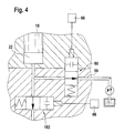
- Figure 4 detail a modified version of the Fuel injector.
- FIG 1 is a fuel injection device for a Internal combustion engine of a motor vehicle shown.
- the Internal combustion engine is preferably a self-igniting Internal combustion engine.
- the fuel injector is preferably designed as a so-called pump-nozzle system and points for each cylinder of the internal combustion engine a high pressure fuel pump 10 and one with this connected fuel injector 12 that leads to a Unit are summarized.
- the Fuel injection device also as a so-called pump-line-nozzle system be trained, also for each cylinder of the internal combustion engine High pressure fuel pump 10 and that Fuel injection valve 12 are provided, but with Are spaced from each other and via a line are interconnected.
- the high pressure fuel pump 10 has one in a cylinder bore 16 of a pump body 14 tightly guided pump piston 18 by a Cam 20 of a camshaft of the internal combustion engine directly or via a transmission element, for example in the form a rocker arm against the force of a return spring 19 is driven in one stroke.
- the pump piston 18 delimits a pump work space in the cylinder bore 16 22, in the fuel 18 during the delivery stroke of the pump piston is compressed under high pressure.
- the pump work room 22 is by means of the delivery pressure of a delivery pump 21st Fuel from a fuel tank 9 of the Motor vehicle supplied.
- the fuel injection valve 12 has one with the Pump body 14 connected valve body 26, the can be formed in several parts, in which a Injection valve member 28 in a bore 30 is guided longitudinally.
- the valve body 26 instructs its the combustion chamber of the cylinder of the internal combustion engine facing end region at least one, preferably several Injection openings 32 on.
- the injection valve member 28 has at its end area facing the combustion chamber for example, approximately conical sealing surface 34, which with one in the valve body 26 in its facing the combustion chamber End region trained valve seat 36 cooperates from after or after which the injection openings 32 discharge.
- valve body 26 in the Valve body 26 is between the injection valve member 28 and an annular space 38 toward the bore 30 toward the valve seat 36 available, the one facing away from the valve seat 36 End area through a radial expansion of the bore 30 in a pressure chamber 40 surrounding the injection valve member 28 transforms.
- the injection valve member 28 has the level of Pressure chamber 40 by reducing a cross section Pressure shoulder 42 on.
- Injector member 28 engages a biased one Closing spring 44 through which the injection valve member 28 is pressed towards the valve seat 36.
- the closing spring 44 is arranged in a spring chamber 46 of the valve body 26, the connects to the bore 30.
- the pressure chamber 40 has a connection 54 to the pump workspace 22, the by one through the pump body 14 and the valve body 26 extending channel is formed. Connection 54 will hereinafter referred to as pressure chamber connection 54. Of the Pressure chamber connection 54 branches a connection 56 to Control pressure chamber 52, so that the control pressure chamber 52nd is also connected to the pump work space 22. The Connection 56 is subsequently called the control pressure chamber connection 56 designated.
- the fuel injection device has a first one electrically operated control valve 60 through which one Connection 59 of the pump workspace 22 with a Relief chamber is controlled as the the pressure side of the Feed pump 21 and thus at least indirectly the Fuel tank 9 can serve.
- the connection 59 is subsequently referred to as the relief space connection 59 designated.
- the relief space connection 59 branches upstream of that leading to the control pressure chamber 52 Control pressure chamber connection 56 from the pressure chamber connection 54 from. Downstream after the branch of the Relief chamber connection 59 to the relief chamber 9 and upstream in front of the branch to the control pressure chamber 52 leading control pressure chamber connection 56 is in the Pressure chamber connection 54 a shut-off valve in the form of a Check valve 62 is arranged, the pressure chamber 40 out opens and closes to the pump work space 22.
- the Check valve 62 has a closing spring 63 loaded valve member 64, against the force of Closing spring 63 to the pressure chamber 40 in the opening direction is movable.
- the first control valve 60 has an actuator 61, which is a Electromagnet or a piezo actuator can be electrical is controlled and through which a valve member of the Control valve 60 is movable.
- the first control valve 60 can be pressure balanced or not pressure balanced be trained.
- the first control valve 60 is a 2/2-way valve trained and through this is in a first Switch position the relief chamber connection 59 to Relief chamber 9 opened and in a second Switch position, the relief chamber connection 59 to Relief chamber 9 separated.
- the control valve 60 is by an electrical control device 66 depending on Operating parameters of the internal combustion engine controlled.
- a second electrically operated control valve 68 is provided, through which a connection 70 of the control pressure chamber 52 with a relief space, for example at least indirectly the fuel tank 9 is controlled.
- the Connection 70 is subsequently referred to as a relief space connection 70 designated.
- the second control valve 68 has an actuator 69, which can be an electromagnet or a piezo actuator, which is controlled electrically and by the one Valve member of the control valve 68 is movable.
- the second Control valve 68 is preferably pressure balanced educated.
- the second control valve 68 is a 2/2-way valve trained by the in a first Switch position the relief chamber connection 70 of the Control pressure chamber 52 is opened with the relief chamber 9 and by the in a second switching position Relief chamber connection 70 of the control pressure chamber 52 with the Relief chamber 9 is separated.
- In the Control pressure chamber connection 56 of the control pressure chamber 52 with the A throttle point 58 is provided in the pressure chamber connection 54 and in the relief space connection 70 of the control pressure space 52 with the relief chamber 9 is another throttling point 71 provided.
- the throttling points 58, 71 allow one Adjustment of the inflow of fuel into the Control pressure chamber 52 or the outflow of fuel from the Control pressure chamber 52.
- the second control valve 68 is also controlled by the control device 66.
- the Control of the control valves 60,68 by the Control device 66 takes place depending on operating parameters the internal combustion engine, such as speed, load and temperature.
- the control device 66 opened the first control valve 60 so that the Pump work chamber 22 connected to the relief chamber 9 is.
- the check valve 62 closes, so that in Pressure chamber 40 and the control pressure chamber 52 fuel under Pressure remains stored.
- the second control valve by the control device 66 68 opened so that the control pressure chamber 52 is relieved and the injection valve member 28 through the in the pressure chamber 40th prevailing pressure opens.
- the pre-injection takes place with the pressure level below which the fuel in the pressure chamber 40 is saved.
- the end of the pre-injection second control valve 68 by the control device 66 again closed so that the injection valve member 28 due to the increased pressure in the control pressure chamber 52 closes. It can also several pre-injections separated from each other corresponding opening and closing of the second Control valve 68 take place.
- the first control valve 60 by the control device 66 closed at the beginning of the delivery stroke of the pump piston 18 is so that the pump piston 18 when the second is closed Control valve 68 fuel in the pressure chamber 40 and Control pressure chamber 52 promotes.
- the pump work space 22 is then relieved and the check valve 62 closes so that Fuel under pressure in the pressure chamber 40 and in Control pressure chamber 52 remains stored.
- Control valve 68 opened so that the control pressure chamber 52nd is relieved and the injection valve member 28 by the im Pressure chamber 40 prevailing pressure opens.
- the pre-injection is ended when the pressure in the pressure chamber 40 is so strong has dropped that by the closing spring 44 on the Injection valve member 28 is greater than the force exerted by the pressure prevailing in the pressure chamber 40 Opening direction on the injection valve member 28 caused Force and the injector member 28 closes.
- the first Control valve 60 through controller 66 to start of the delivery stroke of the pump piston 18 is closed.
- the Cam 20 has a shape such that through this a delivery stroke of the Pump piston 18 is effected so that by the pump piston 18 fuel into the pressure chamber 40 and the control pressure chamber 52 is promoted when the second control valve 68 is closed. In a subsequent range of rotation angle of the cam 20 this shaped such that no further delivery stroke of the Pump piston 18 takes place.
- the speed C of the Pump piston 18 in which caused by the cam 20 Stroke movement over the angle of rotation ⁇ of the cam 20 is in Figure 3 shown, the speed when through the stroke caused by the first rotation angle range is denoted by I.
- the time interval of the The main injection from the pre-injection is made by the Time of opening of the second control valve 68 by the Control device 66 determines. If the main injection Should start with a little pressure, so will be the first Control valve 60 by the control device 66 according to the Pre-injection closed at a later time, see above that there is a correspondingly delayed build-up of pressure.
- the time interval of the main injection from the Pre-injection is in turn determined by the time of the Opening of the second control valve 68 is determined.
- the second Control valve 68 through the control device 66 before The beginning of the main injection is opened so that the Control pressure chamber 52 is relieved.
- the first control valve 60 is closed by the control device 66 and the Main injection begins when the pressure in the pressure chamber 40 is so is high that the injection valve member 28 against the Force of the closing spring 44 opens.
- To end the Main injection is the second control valve 68 through the Control device 66 closed and / or the first Control valve 60 opened.
- fuel in the pressure chamber 40 and in Control pressure space 52 can be stored.
- the amount of pressure under which the fuel is stored is by the Time of closing of the second control valve 68 at the completion of the main injection. The earlier that second control valve 68 is closed, the higher the Pressure under which the fuel in the pressure chamber 40 and in Control pressure chamber 52 is stored.
- the second control valve 68 through the Control device 66 opened again so that the Control pressure chamber 52 is relieved and that Injection valve member 28 opens.
- the post-injection corresponds to one designated by III in FIG Injection phase.
- the post-injection is ended by the second control valve 68 by the control device 66 is closed.
- the one at post-injection injected fuel does not need at the time of Post-injection can be promoted by the pump piston 18, but becomes the pressure chamber 40 and the control pressure chamber 52 taken into which the fuel through the pump piston 18th promoted by its production stroke in an earlier phase has been.
- the first control valve 60 can after completion of the Main injection remains open.
- the Post injection is stopped by the second control valve 68 is closed by the control device 66 and / or when the pressure in the pressure chamber 40 has dropped so much that the closing force on the injection valve member 28 is greater than that generated by the pressure in the pressure chamber 40 Opening force and the injection valve member 28 closes.
- the second control valve 68 through the Control device 66 is closed and for as long remains closed until the pressure in the pressure chamber 40 as a result the leakage has dropped so much that the Injection valve member 28 even when the second one is open Control valve 68 can no longer open. Then will the second control valve 68 briefly opened so that the Pressure chamber 40 and the control pressure chamber 52 are relieved.
- the function of the fuel injector is the same as as described above, but with the shutoff valve 162 is actively switched by the control device 66 since this does not automatically like the check valve 62 an occurring pressure difference opens and closes.
Landscapes
- Engineering & Computer Science (AREA)
- Chemical & Material Sciences (AREA)
- Combustion & Propulsion (AREA)
- Mechanical Engineering (AREA)
- General Engineering & Computer Science (AREA)
- Physics & Mathematics (AREA)
- Fluid Mechanics (AREA)
- Fuel-Injection Apparatus (AREA)
Abstract
Description
Claims (17)
- Kraftstoffeinspritzeinrichtung für eine Brennkraftmaschine mit einer Kraftstoffhochdruckpumpe (10) und einem mit dieser verbundenen Kraftstoffeinspritzventil (12) für jeden Zylinder der Brennkraftmaschine, wobei die Kraftstoffhochdruckpumpe (10) einen durch die Brennkraftmaschine in einer Hubbewegung angetriebenen Pumpenkolben (18) aufweist, der einen Pumpenarbeitsraum (22) begrenzt, der mit einem Druckraum (40) des Kraftstoffeinspritzventils (12) verbindbar ist, das ein Einspritzventilglied (28) aufweist, durch das wenigstens eine Einspritzöffnung (32) gesteuert wird und das durch den im Druckraum (40) herrschenden Druck gegen eine Schließkraft (44) in einer Öffnungsrichtung (29) zur Freigabe der wenigstens einen Einspritzöffnung (32) bewegbar ist, mit einem ersten elektrisch betätigten Steuerventil (60), durch das zumindest mittelbar eine Verbindung (59) des Pumpenarbeitsraums (22) mit einem Entlastungsraum (9;21) gesteuert wird und mit einem zweiten elektrisch betätigten Steuerventil (68), durch das der in einem Steuerdruckraum (52) herrschende Druck gesteuert wird, durch den das Einspritzventilglied (28) zumindest mittelbar in Schließrichtung beaufschlagt ist, dadurch gekennzeichnet, daß in der Druckraumverbindung (54) des Pumpenarbeitsraums (22) mit dem Druckraum (40) ein Absperrventil (62;162) angeordnet ist, durch das der Druckraum (40) und der Steuerdruckraum (52) vom Pumpenarbeitsraum (22) trennbar sind und daß die Entlastungsraumverbindung (59) des Pumpenarbeitsraums (22) mit dem Entlastungsraum (9), in der das erste Steuerventil (60) angeordnet ist, zwischen dem Pumpenarbeitsraum (22) und dem Absperrventil (62;162) abführt.
- Kraftstoffeinspritzeinrichtung nach Anspruch 1, dadurch gekennzeichnet, daß das Absperrventil als ein zum Pumpenarbeitsraum (22) hin schließendes Rückschlagventil (62) ausgebildet ist.
- Kraftstoffeinspritzeinrichtung nach Anspruch 1, dadurch gekennzeichnet, daß das Absperrventil ein elektrisch betätigtes Steuerventil (162) ist, das zwischen einer geöffneten und geschlossenen Schaltstellung umschaltbar ist.
- Kraftstoffeinspritzeinrichtung nach einem der Ansprüche 1 bis 3, dadurch gekennzeichnet, daß durch das zweite Steuerventil (68) eine Entlastungsraumverbindung (70) des Steuerdruckraums (52) mit einem Entlastungsraum (9) gesteuert wird und daß der Steuerdruckraum (52) eine von der Druckraumverbindung (54) des Pumpenarbeitsraums (22) mit dem Druckraum (40) stromabwärts nach dem Rückschlagventil (62) abführende Steuerdruckraumverbindung (56) mit der Druckraumverbindung (54) aufweist.
- Kraftstoffeinspritzeinrichtung nach Anspruch 4, dadurch gekennzeichnet, daß in der Entlastungsraumverbindung (70) des Steuerdruckraums (52) mit dem Entlastungsraum (9) und/oder in der Steuerdruckraumverbindung (56) des Steuerdruckraums (52) mit der Druckraumverbindung (54) eine Drosselstelle (58;71) vorgesehen ist.
- Kraftstoffeinspritzeinrichtung nach Anspruch 4 oder 5, dadurch gekennzeichnet, daß zu Beginn eines Förderhubs des Pumpenkolbens (18) das erste Steuerventil (60) und das zweite Steuerventil (68) geschlossen werden, so daß bei geöffnetem Absperrventil (62;162) Kraftstoff in den Druckraum (40) und den Steuerdruckraum (52) gefördert wird, daß im Verlauf des Förderhubs des Pumpenkolbens (18) das erste Steuerventil (60) geöffnet wird, wobei das Absperrventil (62;162) geschlossen wird, und daß für wenigstens eine Voreinspritzung das zweite Steuerventil (68) geöffnet wird, so daß der Steuerdruckraum (52) entlastet ist und das Einspritzventilglied (28) durch den im Druckraum (40) herrschenden Druck öffnet.
- Kraftstoffeinspritzeinrichtung nach Anspruch 6, dadurch gekennzeichnet, daß zur Beendigung der wenigstens einen Voreinspritzung das zweite Steuerventil (68) geschlossen wird, so daß das Einspritzventilglied (28) durch den im Steuerdruckraum (52) herrschenden Druck schließt.
- Kraftstoffeinspritzeinrichtung nach Anspruch 6, dadurch gekennzeichnet, daß die wenigstens eine Voreinspritzung beendet wird, wenn der im Druckraum (40) herrschende Druck so stark gesunken ist, daß das Einspritzventilglied (28) durch die Schließkraft (44) schließt.
- Kraftstoffeinspritzeinrichtung nach Anspruch 8, dadurch gekennzeichnet, daß das erste Steuerventil (60) beim Förderhub des Pumpenkolbens (18) für eine definierte Zeitdauer geschlossen wird, um bei geöffnetem Absperrventil (62;162) eine definierte Kraftstoffmenge in den Druckraum (40) und den Steuerdruckraum (52) zu fördern, so daß bei der wenigstens einen Voreinspritzung bis zum Zeitpunkt des Schließens des Einspritzventilglieds (28) eine definierte Kraftstoffmenge eingespritzt wird.
- Kraftstoffeinspritzeinrichtung nach Anspruch 8, dadurch gekennzeichnet, daß der Pumpenkolben (18) durch einen Nocken (20) angetrieben wird, daß der Nocken (20) in einem ersten Drehwinkelbereich eine derart bestimmte Form aufweist, daß der Pumpenkolben (18) einen definierten Förderhub ausführt und bei geöffnetem Absperrventil (62;162) eine definierte Kraftstoffmenge in den Druckraum (40) und den Steuerdruckraum (52) fördert, die bei der Voreinspritzung eingespritzt wird, und daß der Nocken (20) in einem anschließenden Drehwinkelbereich eine derart bestimmte Form aufweist, daß der Pumpenkolben (18) keinen weiteren Förderhub ausführt.
- Kraftstoffeinspritzeinrichtung nach einem der Ansprüche 6 bis 10, dadurch gekennzeichnet, daß während des Förderhubs des Pumpenkolbens (18) nach der wenigstens einen Voreinspritzung das erste Steuerventil (60) und das zweite Steuerventil (68) geschlossen werden und daß für eine nachfolgende Haupteinspritzung das zweite Steuerventil (68) geöffnet wird, so daß der Steuerdruckraum (52) entlastet ist und das Einspritzventilglied (28) durch den im Druckraum (40) herrschenden Druck öffnet.
- Kraftstoffeinspritzeinrichtung nach einem der Ansprüche 6 bis 10, dadurch gekennzeichnet, daß während des Förderhubs des Pumpenkolbens (18) nach der wenigstens einen Voreinspritzung das erste Steuerventil (60) geschlossen wird und das zweite Steuerventil (68) geöffnet wird, so daß der Steuerdruckraum (52) entlastet ist und daß eine nachfolgende Haupteinspritzung erfolgt, wenn der durch den Pumpenkolben (18) bei geöffnetem Absperrventil (62;162) im Druckraum (40) erzeugte Druck so hoch ist, daß durch diesen das Einspritzventilglied (28) gegen die Schließkraft (44) öffnet.
- Kraftstoffeinspritzeinrichtung nach Anspruch 11 oder 12, dadurch gekennzeichnet, daß zur Beendigung der Haupteinspritzung das zweite Steuerventil (68) geschlossen wird.
- Kraftstoffeinspritzeinrichtung nach einem der Ansprüche 11 bis 13, dadurch gekennzeichnet, daß nach der Haupteinspritzung wenigstens eine Nacheinspritzung erfolgt, daß bei der vorhergehenden Haupteinspritzung durch Schließen des zweiten Steuerventils (68) Kraftstoff unter Druck im Druckraum (40) und im Steuerdruckraum (52) gespeichert wird und daß zur Nacheinspritzung das zweite Steuerventil (68) geöffnet wird, so daß der Steuerdruckraum (52) entlastet ist und das Einspritzventilglied (28) durch den im Druckraum (40) herrschenden Druck öffnet.
- Kraftstoffeinspritzeinrichtung nach einem der Ansprüche 11 bis 13, dadurch gekennzeichnet, daß nach der Haupteinspritzung wenigstens eine Nacheinspritzung erfolgt, daß zur Druckerzeugung für die Nacheinspritzung bei geöffnetem Absperrventil (62;162) das erste Steuerventil (60) geschlossen wird und daß zur Nacheinspritzung das zweite Steuerventil (68) geöffnet wird.
- Kraftstoffeinspritzeinrichtung nach einem der Ansprüche 11 bis 15, dadurch gekennzeichnet, daß nach der Haupteinspritzung oder der Nacheinspritzung am Ende eines Einspritzzyklus im Druckraum (40) und im Steuerdruckraum (52) bei geschlossenem zweitem Steuerventil (68) und bei geschlossenem Absperrventil (62;162) Kraftstoff unter einem so hohen Druck gespeichert wird, daß dieser ausreichend ist, um bei einem nachfolgenden Einspritzzyklus bei geöffnetem zweitem Steuerventil (68) die Voreinspritzung durchzuführen.
- Kraftstoffeinspritzeinrichtung nach einem der Ansprüche 11 bis 15, dadurch gekennzeichnet, daß nach der Haupteinspritzung oder der Nacheinspritzung am Ende eines Einspritzzyklus das zweite Steuerventil (68) geöffnet wird, wenn der Druck im Druckraum (40) infolge einer Leckage so stark gesunken ist, daß die durch diesen auf das Einspritzventilglied (28) in Öffnungsrichtung (29) erzeugte Kraft geringer ist als die auf das Einspritzventilglied (28) wirkende Schließkraft (44).
Applications Claiming Priority (2)
| Application Number | Priority Date | Filing Date | Title |
|---|---|---|---|
| DE10158660 | 2001-11-30 | ||
| DE10158660A DE10158660A1 (de) | 2001-11-30 | 2001-11-30 | Kraftstoffeinspritzeinrichtung für eine Brennkraftmaschine |
Publications (2)
| Publication Number | Publication Date |
|---|---|
| EP1316718A2 true EP1316718A2 (de) | 2003-06-04 |
| EP1316718A3 EP1316718A3 (de) | 2004-04-28 |
Family
ID=7707434
Family Applications (1)
| Application Number | Title | Priority Date | Filing Date |
|---|---|---|---|
| EP02022361A Withdrawn EP1316718A3 (de) | 2001-11-30 | 2002-10-08 | Kraftstoffeinspritzeinrichtung für eine Brennkraftmaschine |
Country Status (4)
| Country | Link |
|---|---|
| US (1) | US6796290B2 (de) |
| EP (1) | EP1316718A3 (de) |
| JP (1) | JP2003172228A (de) |
| DE (1) | DE10158660A1 (de) |
Cited By (2)
| Publication number | Priority date | Publication date | Assignee | Title |
|---|---|---|---|---|
| EP1921307A1 (de) * | 2006-11-08 | 2008-05-14 | Delphi Technologies, Inc. | Kraftstoffeinspritzsystem |
| WO2014000865A1 (de) * | 2012-06-25 | 2014-01-03 | L'orange Gmbh | Injektor und kraftstoffeinspritzeinrichtung mit einem solchen |
Families Citing this family (14)
| Publication number | Priority date | Publication date | Assignee | Title |
|---|---|---|---|---|
| DE10146739A1 (de) * | 2001-09-22 | 2003-04-10 | Bosch Gmbh Robert | Kraftstoffeinspritzeinrichtung für eine Brennkraftmaschine |
| DE10146745A1 (de) * | 2001-09-22 | 2003-04-10 | Bosch Gmbh Robert | Kraftstoffeinspritzeinrichtung für eine Brennkraftmaschine |
| DE10213025B4 (de) * | 2002-03-22 | 2014-02-27 | Daimler Ag | Selbstzündende Brennkraftmaschine |
| US7191762B2 (en) * | 2002-03-26 | 2007-03-20 | Volvo Lastvagnar Ab | Fuel injection system |
| EP1359316B1 (de) * | 2002-05-03 | 2007-04-18 | Delphi Technologies, Inc. | Kraftstoffeinspritzeinrichtung |
| WO2004072470A1 (en) * | 2003-02-12 | 2004-08-26 | Robert Bosch Gmbh | Fuel injector pump system with high pressure post injection |
| JP5070913B2 (ja) * | 2007-04-11 | 2012-11-14 | 住友金属工業株式会社 | 燃焼設備の燃料遮断装置及び燃料遮断方法 |
| US7707993B2 (en) * | 2008-06-24 | 2010-05-04 | Caterpillar Inc. | Electronic pressure relief in a mechanically actuated fuel injector |
| WO2014066696A1 (en) * | 2012-10-25 | 2014-05-01 | Picospray, Llc | Fuel injection system |
| JP6156397B2 (ja) * | 2015-01-14 | 2017-07-05 | トヨタ自動車株式会社 | 内燃機関 |
| EP3455498B1 (de) | 2016-05-12 | 2024-07-03 | Briggs & Stratton, LLC | Kraftstoffförderinjektor |
| US10947940B2 (en) | 2017-03-28 | 2021-03-16 | Briggs & Stratton, Llc | Fuel delivery system |
| GB2567011B (en) * | 2017-10-02 | 2021-01-20 | Caterpillar Motoren Gmbh & Co | Fuel injection system for engine system |
| US11668270B2 (en) | 2018-10-12 | 2023-06-06 | Briggs & Stratton, Llc | Electronic fuel injection module |
Citations (1)
| Publication number | Priority date | Publication date | Assignee | Title |
|---|---|---|---|---|
| EP0957261A2 (de) | 1998-05-15 | 1999-11-17 | LUCAS INDUSTRIES public limited company | Brennstoffsystem und Pumpe zur Anwendung in einem solchen System |
Family Cites Families (9)
| Publication number | Priority date | Publication date | Assignee | Title |
|---|---|---|---|---|
| DE4236882C1 (de) * | 1992-10-31 | 1994-04-21 | Daimler Benz Ag | Kraftstoffeinspritzanlage mit einer Hochdruckpumpe und einer gemeinsamen Versorgungsleitung für alle Einspritzdüsen mit Magnetventilsteuerung |
| US5732679A (en) * | 1995-04-27 | 1998-03-31 | Isuzu Motors Limited | Accumulator-type fuel injection system |
| JPH09158810A (ja) * | 1995-10-02 | 1997-06-17 | Hino Motors Ltd | ディーゼルエンジン |
| JPH09209867A (ja) * | 1996-02-07 | 1997-08-12 | Mitsubishi Motors Corp | 燃料噴射装置 |
| AU8735198A (en) * | 1997-07-16 | 1999-02-10 | Cummins Wartsila S.A. | Device for injecting fuel into a diesel engine |
| GB9821929D0 (en) * | 1998-10-09 | 1998-12-02 | Lucas Ind Plc | Fuel system |
| EP1077320B1 (de) * | 1999-08-19 | 2004-11-24 | Nissan Motor Co., Ltd. | Regelung für einen Dieselmotor |
| DE10123995A1 (de) * | 2001-05-17 | 2002-11-21 | Bosch Gmbh Robert | Kraftstoffeinspritzeinrichtung für eine Brennkraftmaschine |
| US6439202B1 (en) * | 2001-11-08 | 2002-08-27 | Cummins Inc. | Hybrid electronically controlled unit injector fuel system |
-
2001
- 2001-11-30 DE DE10158660A patent/DE10158660A1/de not_active Withdrawn
-
2002
- 2002-10-08 EP EP02022361A patent/EP1316718A3/de not_active Withdrawn
- 2002-11-28 JP JP2002345991A patent/JP2003172228A/ja not_active Abandoned
- 2002-12-02 US US10/307,479 patent/US6796290B2/en not_active Expired - Fee Related
Patent Citations (1)
| Publication number | Priority date | Publication date | Assignee | Title |
|---|---|---|---|---|
| EP0957261A2 (de) | 1998-05-15 | 1999-11-17 | LUCAS INDUSTRIES public limited company | Brennstoffsystem und Pumpe zur Anwendung in einem solchen System |
Cited By (3)
| Publication number | Priority date | Publication date | Assignee | Title |
|---|---|---|---|---|
| EP1921307A1 (de) * | 2006-11-08 | 2008-05-14 | Delphi Technologies, Inc. | Kraftstoffeinspritzsystem |
| US7574995B2 (en) | 2006-11-08 | 2009-08-18 | Delphi Technologies, Inc. | Fuel injection system |
| WO2014000865A1 (de) * | 2012-06-25 | 2014-01-03 | L'orange Gmbh | Injektor und kraftstoffeinspritzeinrichtung mit einem solchen |
Also Published As
| Publication number | Publication date |
|---|---|
| EP1316718A3 (de) | 2004-04-28 |
| US20030131825A1 (en) | 2003-07-17 |
| DE10158660A1 (de) | 2003-06-12 |
| JP2003172228A (ja) | 2003-06-20 |
| US6796290B2 (en) | 2004-09-28 |
Similar Documents
| Publication | Publication Date | Title |
|---|---|---|
| EP1316718A2 (de) | Kraftstoffeinspritzeinrichtung für eine Brennkraftmaschine | |
| EP1458970B1 (de) | Kraftstoffeinspritzeinrichtung für eine brennkraftmaschine | |
| EP1316717B1 (de) | Kraftstoffeinspritzeinrichtung für eine Brennkraftmaschine | |
| EP1363015A1 (de) | Kraftstoffeinspritzeinrichtung für eine Brennkraftmaschine | |
| EP1241347B1 (de) | Kraftstoffeinspritzeinrichtung für Brennkraftmaschinen | |
| EP1260700B1 (de) | Kraftstoffeinspritzeinrichtung für eine Brennkraftmaschine | |
| EP1312792B1 (de) | Kraftstoffspritzeinrichtung für eine Brennkraftmaschine | |
| WO2003018990A2 (de) | Kraftstoffeinspritzeinrichtung für eine brennkraftmaschine | |
| DE10113654A1 (de) | Kraftsotffeinspritzeinrichtung für Brennkraftmaschinen | |
| DE10205185A1 (de) | Kraftstoffeinspritzeinrichtung für eine Brennkraftmaschine | |
| EP1595074A1 (de) | Kraftstoffeinspritzeinrichtung für eine brennkraftmaschine | |
| EP1310668B1 (de) | Kraftstoffeinspritzeinrichtung für eine Brennkraftmaschine | |
| EP1260702B1 (de) | Kraftstoffeinspritzeinrichtung für eine Brennkraftmaschine | |
| EP1236884A2 (de) | Kraftstoffeinspritzeinrichtung für Brennkraftmaschinen | |
| WO2003054375A1 (de) | Kraftstoffeinspritzeinrichtung für eine brennkraftmaschine | |
| EP1310667A2 (de) | Kraftstoffeinspritzeinrichtung für eine Brennkraftmaschine | |
| DE10207045A1 (de) | Kraftstoffeinspritzeinrichtung für eine Brennkraftmaschine | |
| EP1552138B1 (de) | Kraftstoffeinspritzeinrichtung für eine brennkraftmaschine | |
| WO2003027490A1 (de) | Kraftstoffeinspritzeinrichtung für eine brennkraftmaschine | |
| WO2003052259A1 (de) | Kraftstoffeinspritzeinrichtung für eine brennkraftmaschine | |
| WO2002075149A1 (de) | Kraftstoffeinspritzventil für brennkraftmaschinen | |
| WO2006018334A1 (de) | Kraftstoffeinspritzeinrichtung für einen zylinder einer brennkraftmaschine | |
| WO2003027481A1 (de) | Kraftstoffeinspritzeinrichtung für eine brennkraftmaschine | |
| WO2004046539A1 (de) | Kraftstoffeinspritzventil einer kraftstoffeinspritzeinrichtung für eine aftmaschine |
Legal Events
| Date | Code | Title | Description |
|---|---|---|---|
| PUAI | Public reference made under article 153(3) epc to a published international application that has entered the european phase |
Free format text: ORIGINAL CODE: 0009012 |
|
| AK | Designated contracting states |
Designated state(s): AT BE BG CH CY CZ DE DK EE ES FI FR GB GR IE IT LI LU MC NL PT SE SK TR |
|
| AX | Request for extension of the european patent |
Extension state: AL LT LV MK RO SI |
|
| PUAL | Search report despatched |
Free format text: ORIGINAL CODE: 0009013 |
|
| AK | Designated contracting states |
Kind code of ref document: A3 Designated state(s): AT BE BG CH CY CZ DE DK EE ES FI FR GB GR IE IT LI LU MC NL PT SE SK TR |
|
| AX | Request for extension of the european patent |
Extension state: AL LT LV MK RO SI |
|
| RIC1 | Information provided on ipc code assigned before grant |
Ipc: 7F 02M 63/00 B Ipc: 7F 02M 59/36 B Ipc: 7F 02M 47/02 B Ipc: 7F 02M 45/04 B Ipc: 7F 02M 45/02 B Ipc: 7F 02M 57/02 A |
|
| 17P | Request for examination filed |
Effective date: 20041028 |
|
| 17Q | First examination report despatched |
Effective date: 20041125 |
|
| AKX | Designation fees paid |
Designated state(s): DE ES FR GB IT |
|
| STAA | Information on the status of an ep patent application or granted ep patent |
Free format text: STATUS: THE APPLICATION HAS BEEN WITHDRAWN |
|
| 18W | Application withdrawn |
Effective date: 20051123 |