EP1316683A2 - Ölpumpenkombination für eine Brennkraftmaschine - Google Patents
Ölpumpenkombination für eine Brennkraftmaschine Download PDFInfo
- Publication number
- EP1316683A2 EP1316683A2 EP02025133A EP02025133A EP1316683A2 EP 1316683 A2 EP1316683 A2 EP 1316683A2 EP 02025133 A EP02025133 A EP 02025133A EP 02025133 A EP02025133 A EP 02025133A EP 1316683 A2 EP1316683 A2 EP 1316683A2
- Authority
- EP
- European Patent Office
- Prior art keywords
- pump
- oil
- combustion engine
- internal combustion
- oil pump
- Prior art date
- Legal status (The legal status is an assumption and is not a legal conclusion. Google has not performed a legal analysis and makes no representation as to the accuracy of the status listed.)
- Granted
Links
Images




Classifications
-
- F—MECHANICAL ENGINEERING; LIGHTING; HEATING; WEAPONS; BLASTING
- F01—MACHINES OR ENGINES IN GENERAL; ENGINE PLANTS IN GENERAL; STEAM ENGINES
- F01M—LUBRICATING OF MACHINES OR ENGINES IN GENERAL; LUBRICATING INTERNAL COMBUSTION ENGINES; CRANKCASE VENTILATING
- F01M1/00—Pressure lubrication
- F01M1/02—Pressure lubrication using lubricating pumps
-
- F—MECHANICAL ENGINEERING; LIGHTING; HEATING; WEAPONS; BLASTING
- F01—MACHINES OR ENGINES IN GENERAL; ENGINE PLANTS IN GENERAL; STEAM ENGINES
- F01M—LUBRICATING OF MACHINES OR ENGINES IN GENERAL; LUBRICATING INTERNAL COMBUSTION ENGINES; CRANKCASE VENTILATING
- F01M1/00—Pressure lubrication
- F01M1/02—Pressure lubrication using lubricating pumps
- F01M2001/0253—Pressure lubrication using lubricating pumps characterised by the pump driving means
- F01M2001/0269—Pressure lubrication using lubricating pumps characterised by the pump driving means driven by the crankshaft
-
- F—MECHANICAL ENGINEERING; LIGHTING; HEATING; WEAPONS; BLASTING
- F01—MACHINES OR ENGINES IN GENERAL; ENGINE PLANTS IN GENERAL; STEAM ENGINES
- F01M—LUBRICATING OF MACHINES OR ENGINES IN GENERAL; LUBRICATING INTERNAL COMBUSTION ENGINES; CRANKCASE VENTILATING
- F01M1/00—Pressure lubrication
- F01M1/12—Closed-circuit lubricating systems not provided for in groups F01M1/02 - F01M1/10
- F01M2001/123—Closed-circuit lubricating systems not provided for in groups F01M1/02 - F01M1/10 using two or more pumps
Definitions
- the invention is based on an oil pump combination for an internal combustion engine the features of the preamble of claim 1.
- tandem pumps are also known from the prior art, in which Pump housing several pump stages are arranged and thus, for example, two Suction and discharge sides to supply different consumers can be trained.
- an internal gear pump is known in which two inner rotors are driven by a common drive shaft.
- gear pumps are characterized by a small construction volume and a high power density robust and suitable for tough operating conditions.
- a disadvantage is often too high Noise development in the aforementioned double pumps due to their Multi-stage are particularly pronounced.
- the object of the invention is therefore the oil pump combination described above to improve their noise level.
- An optimal design for reducing the noise of the oil pump combination results when the two drive gears of the main oil pump and the oil suction pump for the exhaust gas turbocharger by one 1 ⁇ 2 tooth each and by each other a 1 ⁇ 4 tooth are offset from each other.
- Volume flow pulsations can be further reduced if the outputs of two Pump stages are merged into a common output.
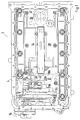
- the oil collecting housing shown in Fig. 1, hereinafter referred to as oil pan 2 is in the assembled state with its flange surface 4 on a flange surface 6 Crankcase lower part 8, a so-called bedplate, attached.
- a lubricating oil pump 10 designed as a double pump attached.
- a first oil collecting space 12 is formed, in which the oil required for the supply of lubricating oil accumulates in an oil sump.
- an oil snorkel 14 is arranged over a first Oil suction line 16 to a suction side of a first pump stage 18 of the double oil pump 10 leads.
- a second, rear oil collecting space 20 is formed in the oil pan 2 the lowest point of which is also an oil snorkel 22, which is connected to a second one Oil suction line 24 with a suction side of a second pump stage 26 of the oil pump 10 connected is.
- a plastic insert 28 is inserted, the two Separates oil collection spaces 12 and 20.
- the insert 28 serves as an oil barrier and also prevents the lubricating oil from running out when driving uphill the first oil collection chamber 12 in the crank chamber and / or in the second Oil collecting space 20 can cross.
- the lubricating oil is in the second oil collecting space 20 from the main bearings of the crankshaft and the lubricating oil from the ones not shown Spray nozzles for the piston cooling collected and via the second oil suction line 24 in promoted the first oil collection chamber 12.
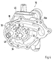
- the lubricating oil pump 10 has a first, made of two meshing gears 30 and 32 existing pump stage 18, the gears 30 and 32 the Separate pump stage 18 into a suction side 34 and a pressure side 36.
- the print page 36 leads via a pressure channel 37 to a pressure outlet 38 via which the consumer the internal combustion engine, such as. B. main or connecting rod bearings, supplied with lubricating oil become.
- the second pump stage 26 also consists of two intermeshing Gears 40 and 42, which are also the pump stage 26 analogous to the first pump stage 18 separate into a suction side and a pressure side.
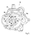
- the housing of the oil pump 10 is constructed in three parts and consists of a basic housing 10a and two am Basic housing attached cover elements 10b and 10c.
- the top of the Base housing 10a has an opening 44 which is connected to the pressure side of the second Pump stage 26 is connected.
- the opening 44 has a tub-like border 46 enclosed. That from the second oil collection space 20 via the second Oil suction line 24 extracted lubricating oil passes through the pressure side of the second Pump stage 26 and through the opening 44 into the riser chimney trough-like border 46. A certain amount of lubricating oil can be collected there be before the part of the Lubricating oil runs through the oil pump housing 10 into the first oil collection space 12.
- the lubricating oil can defoam and those with a lower density Gas components of the lubricating oil via a not shown Crankcase ventilation device are discharged to the outside.
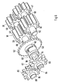
- the two drive gears 30 and 40 of the two pump stages 18 and 26 of the Lubricating oil pump 10 are arranged on a common axis 48, the Drive gear 30 of first pump stage 18 is shrunk onto axis 48, while the drive gear 40 of the second pump stage 26 via a tongue and groove Connection is fixed on the axis 48.
- the two gears 30 and 40 are Angularly offset on the axis 48, such that it is around a 1 ⁇ 2 tooth are offset from one another so that the teeth of the gear 30 with the Tooth gaps of the gear 40 are brought into register, and vice versa.
- the axis 50 conceivable as a fixed bolt that is pressed into the housing is. In this case, both the gear 32 and the gear 42 are only on the Axis 50 pushed on and rotatably mounted.
- the two drive gears 30, 40 of the two pump stages 18 and 26 are over a sprocket 52, which in turn has a chain drive with a not shown Crankshaft gear is connected, driven.
- a turbocharger suction pump 54 At the front of the oil pan 2 is further flanged a turbocharger suction pump 54, which is also via the Chain gear 52 is driven.
- the one attached to the axis 48 Chain gear 52 is provided with a driver 56, in which an intermediate piece 58 one Oldham - clutch 60 engages.
- existing oil suction pump 54 are also arranged two pump stages. A first one Pump stage 62 is received in the housing half 54a, while a second Pump stage 64 is accommodated in the housing half 54b.
- Both pump stages 62, 64 are separated from one another and sealed by an intermediate plate 66.
- the Housing half 54b has two inlet ports 68 and 70, the inlet port 68 leads to the suction side of the first pump stage 62, while the inlet connection 70 leads to the Suction side of the second pump stage 64 leads.
- To connect the inlet connector 68 to the suction side of the first pump stage 62 in the intermediate plate 66 is one with the Entry port 68 corresponding opening 69 is provided, which with the help of a Sealing ring 71 is sealed against the second pump stage 64.
- the two Inlet ports 68, 70 are connected to oil suction lines, not shown, which each lead to a drive shaft of an exhaust gas turbocharger and via which the Lubricating oil supplied to drive shafts is extracted.
- the housing half 54a is with a Provided outlet opening 72, with the help of which via the two pump stages 62 and 64 extracted oil is returned to the oil sump of the oil pan 2.
- the two pressure sides of the pump stages 62 and 64 via one in the intermediate plate 66 arranged opening 74 connected to each other.
- the two on a common Drive gears 78 and 82 arranged on axis 76 are analogous to FIGS Drive gears 30 and 40 of the main oil pump 10 offset by 1 ⁇ 2 tooth arranged to each other, d. H. the teeth of the drive gear 78 are with the Tooth gaps of the drive gear 82 brought into register, and vice versa.
- the two output gears 80 and 84 of the first and second pump stage the oil suction pump 54 is offset from one another by half a tooth.
- the Drive gear 78 is shrunk on axis 76 while the drive gear 82 is arranged in a rotationally fixed manner on the axis 76 via a key / spring connection. That on An output gear 80 arranged on an axis 86 is merely plugged onto this, while the output gear 84 is shrunk on the axis 86.
- the walls W1, W2, W3 and W4 via which the oil to be pumped is completed between the teeth (suction side) or released again (pressure side), beveled so that the respective process not suddenly, but takes place evenly.
- the bevel advantageously runs in a range of 1 ⁇ 2 to 1 tooth, i.e. e.g. for pump wheels with 11 teeth in one Angular range from 0.5 * 360 ° / 11 to 1 * 360 ° / 11.
Landscapes
- Engineering & Computer Science (AREA)
- Mechanical Engineering (AREA)
- General Engineering & Computer Science (AREA)
- Lubrication Of Internal Combustion Engines (AREA)
Abstract
Description
- Fig. 1
- eine Draufsicht auf eine Ölauffangvorrichtung,
- Fig. 2
- eine an ein Kurbelgehäuseunterteil angeflanschte Hauptölpumpe,
- Fig. 3
- die Hauptölpumpe mit angeflanschter Ölabsaugpumpe für zwei Abgasturbolader,
- Fig. 4
- eine Ansicht auf das Grundgehäuse der Hauptölpumpe,
- Fig. 5
- eine Ansicht auf das Grundgehäuse der Hauptölpumpe ohne eingesetzte Zahnräder,
- Fig. 6
- eine Darstellung der Zahnradpaare der Hauptölpumpe und der Ölabsaugpumpe,
- Fig. 7
- eine Ansicht auf die Zahnradpaarungen,
- Fig. 8
- eine erste Seitenansicht der Ölabsaugpumpe,
- Fig. 9
- eine zweite Seitenansicht der Ölabsaugpumpe und
- Fig. 10
- eine Ansicht auf eine Pumpenstufe der Ölabsaugpumpe.
Claims (2)
- Ölpumpenkombination für eine mit zwei Zylinderreihen versehene aufgeladene Brennkraftmaschine, die folgende Merkmale aufweist:eine mit einem Pumpengehäuse versehene Hauptölpumpe (10) zur Absaugung des in einer Ölauffangvorrichtung (2) befindlichen Schmieröls,im Pumpengehäuse sind mindestens zwei Pumpenräume ausgebildet, wobei in jedem Pumpenraum ein Paar von ineinander kämmenden Zahnrädern (30, 32 bzw. 40, 42) zur Ausbildung jeweils einer Pumpenstufe angeordnet ist,eine mit zwei Pumpenräumen versehene Ölabsaugpumpe (54) für die Abgasturbolader der Brennkraftmaschine, wobei in jedem Pumpenraum jeweils ein Paar von ineinander kämmenden Zahnrädern (78, 80 bzw. 82, 84) zur Ausbildung jeweils einer Pumpenstufe (62, 64) angeordnet ist,die beiden Antriebszahnräder (30, 40) der Hauptölpumpe (10) und die beiden Antriebszahnräder (78, 82) der Ölabsaugpumpe (54) sind sowohl untereinander als auch zueinander drehwinkelversetzt angeordnet.
- Ölpumpenkombination nach Anspruch 1, dadurch gekennzeichnet, dass die beiden Antriebszahnräder (30, 40) der Hauptölpumpe (10) und der Ölabsaugpumpe (54) untereinander um jeweils einen ½ Zahn und zueinander um jeweils einen ¼ Zahn drehwinkelversetzt zueinander angeordnet sind.
Applications Claiming Priority (2)
| Application Number | Priority Date | Filing Date | Title |
|---|---|---|---|
| DE10159088A DE10159088A1 (de) | 2001-12-01 | 2001-12-01 | Ölpumpenkombination für eine Brennkraftmaschine |
| DE10159088 | 2001-12-01 |
Publications (3)
| Publication Number | Publication Date |
|---|---|
| EP1316683A2 true EP1316683A2 (de) | 2003-06-04 |
| EP1316683A3 EP1316683A3 (de) | 2004-01-21 |
| EP1316683B1 EP1316683B1 (de) | 2005-05-25 |
Family
ID=7707730
Family Applications (1)
| Application Number | Title | Priority Date | Filing Date |
|---|---|---|---|
| EP02025133A Expired - Lifetime EP1316683B1 (de) | 2001-12-01 | 2002-11-09 | Ölpumpenkombination für eine Brennkraftmaschine |
Country Status (2)
| Country | Link |
|---|---|
| EP (1) | EP1316683B1 (de) |
| DE (2) | DE10159088A1 (de) |
Cited By (5)
| Publication number | Priority date | Publication date | Assignee | Title |
|---|---|---|---|---|
| US6896489B2 (en) | 2000-12-12 | 2005-05-24 | Borgwarner Inc. | Variable displacement vane pump with variable target regulator |
| EP1754868A3 (de) * | 2005-07-28 | 2008-06-18 | J.C. Bamford Excavators Ltd. | Schmierstoffsversorgung zu einer Brennkraftmaschine |
| US7544052B2 (en) * | 2005-06-23 | 2009-06-09 | Dr. Ing. H.C.F. Porsche Aktiengesellschaft | Oil pump for an internal combustion engine |
| US20120051950A1 (en) * | 2010-08-27 | 2012-03-01 | Chang Chun-Hsien | Engine oil pump provided automatic adjustment of oil supply amount |
| CN115507016A (zh) * | 2021-06-22 | 2022-12-23 | Fte汽车有限责任公司 | 齿轮泵和驱动机器 |
Families Citing this family (6)
| Publication number | Priority date | Publication date | Assignee | Title |
|---|---|---|---|---|
| US7674095B2 (en) | 2000-12-12 | 2010-03-09 | Borgwarner Inc. | Variable displacement vane pump with variable target regulator |
| EP1350930B2 (de) | 2002-04-03 | 2016-01-27 | SLW Automotive Inc. | Regelbare Verdrängerpump sowie Steursystem dafür |
| US7726948B2 (en) | 2002-04-03 | 2010-06-01 | Slw Automotive Inc. | Hydraulic pump with variable flow and variable pressure and electric control |
| DE102005029084B4 (de) | 2005-06-23 | 2022-11-03 | Dr. Ing. H.C. F. Porsche Aktiengesellschaft | Ölpumpe für eine Brennkraftmaschine |
| DE102006027660A1 (de) * | 2006-06-14 | 2007-12-20 | Schwäbische Hüttenwerke Automotive GmbH & Co. KG | Ölpumpenvorrichtung für eine Brennkraftmaschine mit einer Ölwanne |
| DE102024105468A1 (de) | 2024-02-27 | 2025-08-28 | Valeo Embrayages | Hydraulikmodul sowie Baugruppe mit einem solchen Hydraulikmodul |
Citations (2)
| Publication number | Priority date | Publication date | Assignee | Title |
|---|---|---|---|---|
| DE19820565A1 (de) | 1997-06-21 | 1999-01-21 | Bayerische Motoren Werke Ag | Innenachsige Zahnradpumpe, insbesondere zum Einsatz in Kraftfahrzeugen |
| DE10014368A1 (de) | 2000-03-23 | 2001-10-04 | Porsche Ag | Ölauffangvorrichtung und Ölpumpe für eine Brennkraftmaschine |
Family Cites Families (7)
| Publication number | Priority date | Publication date | Assignee | Title |
|---|---|---|---|---|
| DE973994C (de) * | 1954-06-26 | 1960-08-11 | Daimler Benz Ag | Zahnradpumpe |
| US3272140A (en) * | 1964-04-02 | 1966-09-13 | Monsanto Chemicals | Metering pump |
| DE2705249A1 (de) * | 1977-02-09 | 1978-08-10 | Bosch Gmbh Robert | Zahnradmaschine (pumpe oder motor) |
| US5092751A (en) * | 1990-10-26 | 1992-03-03 | Viktora Dean C | Split gear pump mechanism with gear offset |
| DE4242217C2 (de) * | 1992-12-15 | 1995-07-20 | Bosch Gmbh Robert | Zahnradmaschine (Pumpe oder Motor) |
| US5755566A (en) * | 1996-08-23 | 1998-05-26 | Kalish Canada Inc. | Self-driving fluid pump |
| DE10144693B4 (de) * | 2001-09-11 | 2012-06-21 | Volkswagen Ag | Zahnradpumpe zur Schmierölversorgung |
-
2001
- 2001-12-01 DE DE10159088A patent/DE10159088A1/de not_active Ceased
-
2002
- 2002-11-09 DE DE50203186T patent/DE50203186D1/de not_active Expired - Lifetime
- 2002-11-09 EP EP02025133A patent/EP1316683B1/de not_active Expired - Lifetime
Patent Citations (2)
| Publication number | Priority date | Publication date | Assignee | Title |
|---|---|---|---|---|
| DE19820565A1 (de) | 1997-06-21 | 1999-01-21 | Bayerische Motoren Werke Ag | Innenachsige Zahnradpumpe, insbesondere zum Einsatz in Kraftfahrzeugen |
| DE10014368A1 (de) | 2000-03-23 | 2001-10-04 | Porsche Ag | Ölauffangvorrichtung und Ölpumpe für eine Brennkraftmaschine |
Cited By (7)
| Publication number | Priority date | Publication date | Assignee | Title |
|---|---|---|---|---|
| US6896489B2 (en) | 2000-12-12 | 2005-05-24 | Borgwarner Inc. | Variable displacement vane pump with variable target regulator |
| US7544052B2 (en) * | 2005-06-23 | 2009-06-09 | Dr. Ing. H.C.F. Porsche Aktiengesellschaft | Oil pump for an internal combustion engine |
| US7967580B2 (en) | 2005-06-23 | 2011-06-28 | Dr. Ing h.c. F. Porsche AG | Oil pump for an internal combustion engine |
| EP1754868A3 (de) * | 2005-07-28 | 2008-06-18 | J.C. Bamford Excavators Ltd. | Schmierstoffsversorgung zu einer Brennkraftmaschine |
| US7516729B2 (en) | 2005-07-28 | 2009-04-14 | J.C. Bamford Excavation Limited | Providing lubricant to an engine |
| US20120051950A1 (en) * | 2010-08-27 | 2012-03-01 | Chang Chun-Hsien | Engine oil pump provided automatic adjustment of oil supply amount |
| CN115507016A (zh) * | 2021-06-22 | 2022-12-23 | Fte汽车有限责任公司 | 齿轮泵和驱动机器 |
Also Published As
| Publication number | Publication date |
|---|---|
| EP1316683B1 (de) | 2005-05-25 |
| DE50203186D1 (de) | 2005-06-30 |
| EP1316683A3 (de) | 2004-01-21 |
| DE10159088A1 (de) | 2003-06-18 |
Similar Documents
| Publication | Publication Date | Title |
|---|---|---|
| EP1316683B1 (de) | Ölpumpenkombination für eine Brennkraftmaschine | |
| DE2316964A1 (de) | Mehrstufiger reihenschleuderkompressor und mehrfachkuehlungseinheit | |
| DE102005029086B4 (de) | Ölpumpe für eine Brennkraftmaschine | |
| DE10014368B4 (de) | Ölauffangvorrichtung für eine Brennkraftmaschine | |
| EP1316685B1 (de) | Brennkraftmaschine mit Schmiervorrichtung eines Abgasturboladers | |
| DE10016071B4 (de) | Schmieranordnung für einen Viertaktmotor | |
| DE60013923T2 (de) | Entlüftungsvorrichtung für ein Kurbelgehäuse mit einem Gasdurchgang zwischen Kurbelgehäuseteilen | |
| CH628709A5 (en) | Roots pump | |
| DE10159090C2 (de) | Ölauffangvorrichtung und Ölpumpe für eine Brennkraftmaschine | |
| EP1399677B1 (de) | Zweistufiger schraubenkompressor | |
| DE3727812C2 (de) | ||
| EP1989465B1 (de) | Vorrichtung zum kräfte- und/oder momentenausgleich für brennkraftmaschinen | |
| DE102004031281B4 (de) | Vorrichtung zum Rückführen von Kurbelgehäuseentlüftungsgasen in den Verbrennungsraum einer aufgeladenen Brennkraftmaschine | |
| EP1691042B1 (de) | Mehrzylindrige Brennkraftmaschine | |
| DE102015121311B4 (de) | Ölpumpe für eine Verbrennungskraftmaschine | |
| DE4241873A1 (en) | Oil pump for engine lubrication - has inner gear and outer gear which form pump chambers with increased suction efficiency | |
| DE3545674A1 (de) | Rotationskolbenverdichter, insbesondere rootsgeblaese | |
| DE19910271B4 (de) | Brennkraftmaschine | |
| EP1316713B1 (de) | Ölauffangvorrichtung für eine Brennkraftmaschine | |
| DE102007007683A1 (de) | Antrieb für mindestens zwei Zusatzaggregate einer Brennkraftmaschine | |
| WO2007093581A1 (de) | Ölpumpen- und vakuumpumpenmodul | |
| DE102007051779A1 (de) | Zahnradschmiermittelpumpe, insbesondere Außenzahnradpumpe | |
| EP1283331B1 (de) | Pumpeinrichtung für Schmiermittel einer Brennkraftmaschine | |
| DE4338677C2 (de) | Pumpe zum Fördern von Fluid, insbesondere als Kraftstoff-Förderaggregat für Kraftfahrzeuge | |
| DE10257012B4 (de) | Brennkraftmaschine |
Legal Events
| Date | Code | Title | Description |
|---|---|---|---|
| PUAI | Public reference made under article 153(3) epc to a published international application that has entered the european phase |
Free format text: ORIGINAL CODE: 0009012 |
|
| AK | Designated contracting states |
Designated state(s): AT BE BG CH CY CZ DE DK EE ES FI FR GB GR IE IT LI LU MC NL PT SE SK TR |
|
| AX | Request for extension of the european patent |
Extension state: AL LT LV MK RO SI |
|
| PUAL | Search report despatched |
Free format text: ORIGINAL CODE: 0009013 |
|
| AK | Designated contracting states |
Kind code of ref document: A3 Designated state(s): AT BE BG CH CY CZ DE DK EE ES FI FR GB GR IE IT LI LU MC NL PT SE SK TR |
|
| AX | Request for extension of the european patent |
Extension state: AL LT LV MK RO SI |
|
| RIC1 | Information provided on ipc code assigned before grant |
Ipc: 7F 04C 11/00 B Ipc: 7F 01M 1/02 A Ipc: 7F 04C 2/16 B |
|
| 17P | Request for examination filed |
Effective date: 20040721 |
|
| AKX | Designation fees paid |
Designated state(s): DE FR GB IT |
|
| GRAP | Despatch of communication of intention to grant a patent |
Free format text: ORIGINAL CODE: EPIDOSNIGR1 |
|
| GRAS | Grant fee paid |
Free format text: ORIGINAL CODE: EPIDOSNIGR3 |
|
| GRAA | (expected) grant |
Free format text: ORIGINAL CODE: 0009210 |
|
| AK | Designated contracting states |
Kind code of ref document: B1 Designated state(s): DE FR GB IT |
|
| REG | Reference to a national code |
Ref country code: GB Ref legal event code: FG4D Free format text: NOT ENGLISH |
|
| REF | Corresponds to: |
Ref document number: 50203186 Country of ref document: DE Date of ref document: 20050630 Kind code of ref document: P |
|
| GBT | Gb: translation of ep patent filed (gb section 77(6)(a)/1977) |
Effective date: 20050907 |
|
| ET | Fr: translation filed | ||
| PLBE | No opposition filed within time limit |
Free format text: ORIGINAL CODE: 0009261 |
|
| STAA | Information on the status of an ep patent application or granted ep patent |
Free format text: STATUS: NO OPPOSITION FILED WITHIN TIME LIMIT |
|
| 26N | No opposition filed |
Effective date: 20060228 |
|
| REG | Reference to a national code |
Ref country code: FR Ref legal event code: TP |
|
| REG | Reference to a national code |
Ref country code: FR Ref legal event code: CD |
|
| REG | Reference to a national code |
Ref country code: FR Ref legal event code: TP |
|
| PGFP | Annual fee paid to national office [announced via postgrant information from national office to epo] |
Ref country code: IT Payment date: 20101124 Year of fee payment: 9 Ref country code: GB Payment date: 20101118 Year of fee payment: 9 |
|
| REG | Reference to a national code |
Ref country code: GB Ref legal event code: 732E Free format text: REGISTERED BETWEEN 20110310 AND 20110316 |
|
| REG | Reference to a national code |
Ref country code: GB Ref legal event code: 732E Free format text: REGISTERED BETWEEN 20110331 AND 20110406 |
|
| GBPC | Gb: european patent ceased through non-payment of renewal fee |
Effective date: 20111109 |
|
| PG25 | Lapsed in a contracting state [announced via postgrant information from national office to epo] |
Ref country code: IT Free format text: LAPSE BECAUSE OF NON-PAYMENT OF DUE FEES Effective date: 20111109 |
|
| PG25 | Lapsed in a contracting state [announced via postgrant information from national office to epo] |
Ref country code: GB Free format text: LAPSE BECAUSE OF NON-PAYMENT OF DUE FEES Effective date: 20111109 |
|
| REG | Reference to a national code |
Ref country code: FR Ref legal event code: PLFP Year of fee payment: 14 |
|
| PGFP | Annual fee paid to national office [announced via postgrant information from national office to epo] |
Ref country code: DE Payment date: 20151105 Year of fee payment: 14 |
|
| PGFP | Annual fee paid to national office [announced via postgrant information from national office to epo] |
Ref country code: FR Payment date: 20151119 Year of fee payment: 14 |
|
| REG | Reference to a national code |
Ref country code: DE Ref legal event code: R119 Ref document number: 50203186 Country of ref document: DE |
|
| REG | Reference to a national code |
Ref country code: FR Ref legal event code: ST Effective date: 20170731 |
|
| PG25 | Lapsed in a contracting state [announced via postgrant information from national office to epo] |
Ref country code: FR Free format text: LAPSE BECAUSE OF NON-PAYMENT OF DUE FEES Effective date: 20161130 |
|
| PG25 | Lapsed in a contracting state [announced via postgrant information from national office to epo] |
Ref country code: DE Free format text: LAPSE BECAUSE OF NON-PAYMENT OF DUE FEES Effective date: 20170601 |