EP1316484A1 - A device at a pillar of a vehicle - Google Patents
A device at a pillar of a vehicle Download PDFInfo
- Publication number
- EP1316484A1 EP1316484A1 EP01128229A EP01128229A EP1316484A1 EP 1316484 A1 EP1316484 A1 EP 1316484A1 EP 01128229 A EP01128229 A EP 01128229A EP 01128229 A EP01128229 A EP 01128229A EP 1316484 A1 EP1316484 A1 EP 1316484A1
- Authority
- EP
- European Patent Office
- Prior art keywords
- pillar
- safety belt
- vehicle
- retractor
- cavity
- Prior art date
- Legal status (The legal status is an assumption and is not a legal conclusion. Google has not performed a legal analysis and makes no representation as to the accuracy of the status listed.)
- Granted
Links
Images

Classifications
-
- B—PERFORMING OPERATIONS; TRANSPORTING
- B60—VEHICLES IN GENERAL
- B60R—VEHICLES, VEHICLE FITTINGS, OR VEHICLE PARTS, NOT OTHERWISE PROVIDED FOR
- B60R22/00—Safety belts or body harnesses in vehicles
- B60R22/18—Anchoring devices
- B60R22/20—Anchoring devices adjustable in position, e.g. in height
-
- B—PERFORMING OPERATIONS; TRANSPORTING
- B60—VEHICLES IN GENERAL
- B60R—VEHICLES, VEHICLE FITTINGS, OR VEHICLE PARTS, NOT OTHERWISE PROVIDED FOR
- B60R22/00—Safety belts or body harnesses in vehicles
- B60R22/18—Anchoring devices
- B60R22/24—Anchoring devices secured to the side, door, or roof of the vehicle
Definitions
- the present invention relates to a device by a pillar of a vehicle, a vehicle comprising said device and a system for reinforcing a pillar of a vehicle.
- B-pillar of a vehicle One of the things the B-pillar of a vehicle is designed for is to handle the force applied by the safety belt system at collisions.
- cross-country trucks have become very popular.
- the centre of gravity In this type of vehicle the centre of gravity is normally higher than in general vehicles. This elevation of the centre of gravity of vehicles has led to an increase in rollover-incidents.
- the compressive strength of the B-pillars have become essential for personal safety in cross country trucks.
- the integration of safety belt devices in B-pillars weakens the compressive strength of the B-pillars.
- devices provided on the B-pillar facing inwards might cause damage at the compression of a B-pillar.
- One of the functions of the pillars of a vehicle including the so-called B-pillar, is to provide support for the roof of the vehicle in the event that the vehicle is involved in an accident which may tend to crush the roof. Ways to enhance this important function can therefore be advantageous.
- the most common safety belt devices comprise a safety belt retractor.
- the retractor is either provided on the floor of the vehicle or directly on the B-pillar, depending upon the specific design criteria for the safety belt system.
- the retractor is mounted by a bracket or similar mounting method on the B-pillar.
- FIG. 1A and 1B A prior art mounting of a seat belt retractor on the B-pillar of a car body is shown in Figures 1A and 1B.
- the carrying device 1 is mounted on the car body 3 with two bolts 5.
- Carrying device 1 is very effective for securely mounting retractor 2 such that retractor 2 can fully carry out its functions.
- carrying device 1 is not designed to provide any additional structural integrity to B-pillar 4.
- the device according to the present invention has a cross section that is preferably essentially U-shaped and when mounted on the B-pillar forms a cavity in combination with the B-pillar, the cavity comprising elements of a safety belt system.
- the U-shape of the device in combination with the U-shape of the B-pillar forms a cavity which is more resistant to compressive forces than alone the U-shaped B-pillar.
- the cavity is preferably of a closed or substantially-closed cross-section.
- elements of the safety belt system are preferably comprised in the device.
- the shifter or the retractor is comprised in the device.
- the safety belt retractor is an automatic height adjusted retractor for automatic height adjustment. Since a retractor of this type requires more space than a regular retractor using a device according to the present invention is most beneficial.
- the device is provided with a predefined bend that in mounted position is directed outwards from the interior of a vehicle. If the compressive forces are large and the B-pillar bends, the device bends in the same direction as the B-pillar.
- the device is provided with an elongate bore with one end thereof having a diameter larger than the width of said elongate bore for mounting purposes.
- a device according to the present invention comprising an automatic height adjusted retractor is quite heavy.
- the device is premounted on the car body. For example, a bolt is screwed into the B-pillar, the head of the bolt being small enough to slip through the one end of the elongated bore with the larger diameter but larger than the width of the rest of the bore.
- the device is made of high-tensile steel.
- a vehicle comprising a device corresponding to the device disclosed above.
- a system for reinforcing the B-pillar of a vehicle comprising a device corresponding to the device disclosed above.
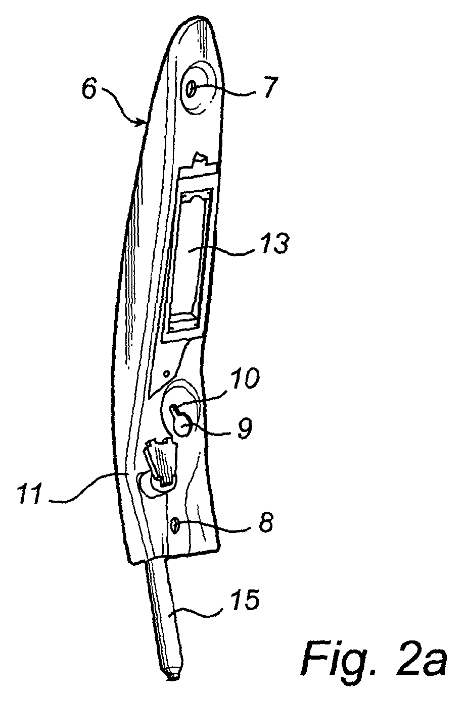
- Figures 2A, 2B and 3 show a device 6, in this case a bracket, according to the present invention.
- the device 6 comprises an upper hole 7 and a lower hole 8 for fixing the device 6 onto the B-pillar 4.
- the device 6 also comprises an intermediate hole 9 with an elongate bore 10 extending from the upper part of the intermediate hole 9.
- a bolt is screwed into the car body 3 and the device 6 is brought to its position and said bolt is fitted in the intermediate hole 9.
- the device 6 is moved downwards so that the elongate bore 10 slides down over the body of the bolt.
- the assembler does not need to carry the entire weight of the device 6 fixing the device via the upper 7 and the lower hole 8, respectively.
- the device 6 comprises a predefined bend 11 following the contours of the B-pillar outwards seen from the interior of the car body. At compression of the B-pillar 4 the device 6 bends outwards together with the B-pillar 4 due to the predefined bend 11. Predefined bend 11 prevents device 6 from bending inwards at compression, preventing intrustion of device 6 into the passenger compartment of the vehicle.
- the device 6 has attached to it a safety belt retractor 12 and suitable means (not shown) for holding the safety belt retractor 12 and an aperture 13 through which the safety belt 14 can pass.
- the aperture 13 height is preferably at least twice the width of the safety belt 14 in order to allow the use of an automatic height adjusted retractor.
- the design of the device 6 is preferably such that it is essentially U-shaped.
- the safety belt retractor 12 is essentially embodied between the device 6 and the B-pillar 4.
- the U-shape of the device 6 in combination with the B-pillar defines a cavity which contributes considerably to the compressive strength of the B-pillar 4.
- the cavity is preferably of a closed or substantially closed cross section, enhancing said compressive strength.
- the device 6 comprises a tensioning device 15.
- Said tensioning device 15 is a equipped with a pyrotechnic charge which is triggered by a collision of the vehicle or a rollover for tensioning of the safety belt 14. This tensioning aims to properly strap down the person using the safety belt 14 and thereby to avoid personal injuries due to bumping into the interior of the vehicle.
- the retractor for the safety belt would be mounted on the floor of the vehicle.
- the device 6 mounted on the B-pillar holds a safety belt shifter, such as a D-loop (as known in the art) where the shifter is provided on a suitable sliding device (not shown) positioned at the same level as the aperture 13 for height adjustment.
- the device 6 is preferably made of high-tensile steel.
- a further advantage with using high-tensile steel is that it decreases the weight of the device 6 and hence the total weight of the vehicle, which is important considering fuel-consumption and mounting the device 6.
Landscapes
- Engineering & Computer Science (AREA)
- Mechanical Engineering (AREA)
- Automotive Seat Belt Assembly (AREA)
Abstract
Description
- The present invention relates to a device by a pillar of a vehicle, a vehicle comprising said device and a system for reinforcing a pillar of a vehicle.
- One of the things the B-pillar of a vehicle is designed for is to handle the force applied by the safety belt system at collisions. In recent years cross-country trucks have become very popular. In this type of vehicle the centre of gravity is normally higher than in general vehicles. This elevation of the centre of gravity of vehicles has led to an increase in rollover-incidents. Thus, the compressive strength of the B-pillars have become essential for personal safety in cross country trucks. However, the integration of safety belt devices in B-pillars weakens the compressive strength of the B-pillars. Also, devices provided on the B-pillar facing inwards might cause damage at the compression of a B-pillar.
- One of the functions of the pillars of a vehicle, including the so-called B-pillar, is to provide support for the roof of the vehicle in the event that the vehicle is involved in an accident which may tend to crush the roof. Ways to enhance this important function can therefore be advantageous.
- The most common safety belt devices comprise a safety belt retractor. The retractor is either provided on the floor of the vehicle or directly on the B-pillar, depending upon the specific design criteria for the safety belt system. In the case of a retractor mounted on the B-pillar, the retractor is mounted by a bracket or similar mounting method on the B-pillar.
- A prior art mounting of a seat belt retractor on the B-pillar of a car body is shown in Figures 1A and 1B. A carrying
device 1, a bracket, carries an automatic height adjustedretractor 2 mounted on acar body 3, more specifically the B-pillar 4 of acar body 3. The carryingdevice 1 is mounted on thecar body 3 with twobolts 5.Carrying device 1 is very effective for securely mountingretractor 2 such thatretractor 2 can fully carry out its functions. However, carryingdevice 1 is not designed to provide any additional structural integrity to B-pillar 4. - An object of the present invention is to provide a device that reinforces the B-pillar of a vehicle, and more specifically reinforces the B-pillar regarding compressive forces. Another object is to provide a vehicle comprising a device, said device reinforcening the B-pillar, and more specifically reinforces the B-pillar regarding compressive forces. A further object is to provide a system for reinforcing the B-pillar of a vehicle.
- These objects are achieved by the device, vehicle and system set forth in the appended claims.
- The device according to the present invention has a cross section that is preferably essentially U-shaped and when mounted on the B-pillar forms a cavity in combination with the B-pillar, the cavity comprising elements of a safety belt system. The U-shape of the device in combination with the U-shape of the B-pillar forms a cavity which is more resistant to compressive forces than alone the U-shaped B-pillar. The cavity is preferably of a closed or substantially-closed cross-section.
- In order to facilitate the mounting of the safety belt system, elements of the safety belt system are preferably comprised in the device. Depending on what kind of safety belt system, the shifter or the retractor is comprised in the device.
- According to one aspect of the invention the safety belt retractor is an automatic height adjusted retractor for automatic height adjustment. Since a retractor of this type requires more space than a regular retractor using a device according to the present invention is most beneficial.
- Further, according to another aspect of the invention the device is provided with a predefined bend that in mounted position is directed outwards from the interior of a vehicle. If the compressive forces are large and the B-pillar bends, the device bends in the same direction as the B-pillar.
- According to another aspect of the invention the device is provided with an elongate bore with one end thereof having a diameter larger than the width of said elongate bore for mounting purposes. A device according to the present invention comprising an automatic height adjusted retractor is quite heavy. In order to simplify the mounting the device is premounted on the car body. For example, a bolt is screwed into the B-pillar, the head of the bolt being small enough to slip through the one end of the elongated bore with the larger diameter but larger than the width of the rest of the bore. Thus, when finally fixing the device to the car body the device need not be lifted. Also, in order to decrease the weight, the device is made of high-tensile steel.
- According to one aspect of the present invention a vehicle is provided comprising a device corresponding to the device disclosed above.
- According to another aspect of the present invention there is provided a system for reinforcing the B-pillar of a vehicle comprising a device corresponding to the device disclosed above.
- The invention is explained below in more detail with reference to the drawings, wherein:
- Figure 1A is a perspective view of a device mounted on a car body, carrying an automatic height adjusted retractor, according to prior art.
- Figure 1B shows the cross-section of the same prior art device and the B-pillar.
- Figure 2A is a perspective view of a device, carrying an automatic height adjusted retractor, according to the present invention.
- Figure 2B shows the cross-section of the same device and the B-pillar.
- Figure 3 is an overall view of a car body with a device according to the present invention.
-
- Figures 2A, 2B and 3 show a
device 6, in this case a bracket, according to the present invention. In a preferred embodiment of the present invention thedevice 6 comprises anupper hole 7 and alower hole 8 for fixing thedevice 6 onto the B-pillar 4. Thedevice 6 also comprises anintermediate hole 9 with anelongate bore 10 extending from the upper part of theintermediate hole 9. When mounting thedevice 6, for instance, a bolt is screwed into thecar body 3 and thedevice 6 is brought to its position and said bolt is fitted in theintermediate hole 9. When the head of the bolt has passed thehole 9 completely, thedevice 6 is moved downwards so that theelongate bore 10 slides down over the body of the bolt. When the bolt is in contact with the upper end of theelongate bore 10, the assembler does not need to carry the entire weight of thedevice 6 fixing the device via the upper 7 and thelower hole 8, respectively. - Further, in a preferred embodiment of the present invention, the
device 6 comprises apredefined bend 11 following the contours of the B-pillar outwards seen from the interior of the car body. At compression of the B-pillar 4 thedevice 6 bends outwards together with the B-pillar 4 due to thepredefined bend 11.Predefined bend 11 preventsdevice 6 from bending inwards at compression, preventing intrustion ofdevice 6 into the passenger compartment of the vehicle. - In a preferred embodiment of the present invention the
device 6 has attached to it asafety belt retractor 12 and suitable means (not shown) for holding thesafety belt retractor 12 and anaperture 13 through which thesafety belt 14 can pass. Theaperture 13 height is preferably at least twice the width of thesafety belt 14 in order to allow the use of an automatic height adjusted retractor. Further, the design of thedevice 6 is preferably such that it is essentially U-shaped. Thus, thesafety belt retractor 12 is essentially embodied between thedevice 6 and the B-pillar 4. The U-shape of thedevice 6 in combination with the B-pillar defines a cavity which contributes considerably to the compressive strength of the B-pillar 4. The cavity is preferably of a closed or substantially closed cross section, enhancing said compressive strength. - Further, in a preferred embodiment of the present invention, the
device 6 comprises atensioning device 15. Said tensioningdevice 15 is a equipped with a pyrotechnic charge which is triggered by a collision of the vehicle or a rollover for tensioning of thesafety belt 14. This tensioning aims to properly strap down the person using thesafety belt 14 and thereby to avoid personal injuries due to bumping into the interior of the vehicle. - In an alternative configuration of a safety belt system, the retractor for the safety belt would be mounted on the floor of the vehicle. In such case, the
device 6 mounted on the B-pillar holds a safety belt shifter, such as a D-loop (as known in the art) where the shifter is provided on a suitable sliding device (not shown) positioned at the same level as theaperture 13 for height adjustment. - For maximum tensile strength the
device 6 is preferably made of high-tensile steel. A further advantage with using high-tensile steel is that it decreases the weight of thedevice 6 and hence the total weight of the vehicle, which is important considering fuel-consumption and mounting thedevice 6. - The foregoing is a disclosure of preferred embodiments for practicing the present invention. However, it is apparent that device incorporating modifications and variations will be obvious to one skilled in the art. Inasmuch as the foregoing disclosure is intended to enable one skilled in the art to practice the instant invention, it should not be construed to be limited thereby, but should be construed to include such modifications and variations as fall within its true spirit and scope.
Claims (22)
- A system for mounting one or more elements (12, 15) of a safety belt system with respect to a pillar (4) of a vehicle body, said system including a device (6) having an essentially U-shaped cross section, said device (6) mounted on said pillar (4) to form a cavity in combination with said pillar, said elements (12, 15) of said safety belt system mounted within said cavity.
- A system according to claim 1, wherein said elements include a safety belt shifter.
- A system according to claim 1, wherein said elements include a safety belt retractor (12).
- A system according to claim 3, wherein said safety belt retractor (12) is an automatic height adjusted retractor for automatic height adjustment.
- A system according to claim 1, wherein the device (6) is provided with a predefined bend (11) that in mounted position is directed outwards from the interior of a vehicle.
- A system according to claim 1, wherein the device (6) is provided with an elongate bore (10) with one end (9) thereof having a diameter larger than the width of said elongate bore (10) for mounting purposes.
- A system according to claim 1, wherein the device (6) is made of high-tensile steel.
- A vehicle comprising a device (6) by the B-pillar (4),
characterised in that the cross section of the device (6) is essentially U-shaped and when mounted on the B-pillar (4) forms a cavity in combination with the B-pillar (4), the cavity comprising elements of a safety belt system. - A vehicle according to claim 8, wherein said device (6) comprises safety belt system elements.
- A vehicle according to claim 8, wherein said device (6) comprises a safety belt shifter.
- A vehicle according to claim 8, wherein said device (6) comprises a safety belt retractor (12).
- A vehicle according to claim 11, wherein said safety belt retractor (12) is an automatic height adjusted retractor for automatic height adjustment.
- A vehicle according to claim 8, wherein said device (6) is provided with a predefined bend (11) that in mounted position is directed outwards from the interior of the vehicle.
- A vehicle according to claim 8, wherein said device (6) is provided with an elongate bore (10) with one end (9) thereof having a diameter larger than the width of said elongate bore for mounting purposes.
- A vehicle according to claim 8, wherein said device (6) is made of high-tensile steel.
- A system for mounting one or more elements (12, 15) of a safety belt system with respect to a pillar (4) of a vehicle body,
characterised in that said system includes a device (6) mounted on said pillar (4) to form a cavity with substantially-closed cross section in combination with said pillar, said elements (12, 15) of said safety belt system mounted within said cavity. - A system according to claim 16, wherein said elements include a safety belt shifter.
- A system according to claim 16, wherein said elements include a safety belt retractor (12).
- A system according to claim 18, wherein said safety belt retractor (12) is an automatic height adjusted retractor for automatic height adjustment.
- A system according to claim 16, wherein the device (6) is provided with a predefined bend (11) that in mounted position is directed outwards from the interior of a vehicle.
- A system according to claim 16, wherein the device (6) is provided with an elongate bore (10) with one end (9) thereof having a diameter larger than the width of said elongate bore (10) for mounting purposes.
- A system according to claim 16, wherein the device (6) is made of high-tensile steel.
Priority Applications (2)
| Application Number | Priority Date | Filing Date | Title |
|---|---|---|---|
| EP01128229A EP1316484B1 (en) | 2001-11-28 | 2001-11-28 | Mounting system for safety belt system |
| US10/065,890 US20030116955A1 (en) | 2001-11-28 | 2002-11-27 | Seatbelt retractor mounting apparatus |
Applications Claiming Priority (1)
| Application Number | Priority Date | Filing Date | Title |
|---|---|---|---|
| EP01128229A EP1316484B1 (en) | 2001-11-28 | 2001-11-28 | Mounting system for safety belt system |
Publications (2)
| Publication Number | Publication Date |
|---|---|
| EP1316484A1 true EP1316484A1 (en) | 2003-06-04 |
| EP1316484B1 EP1316484B1 (en) | 2011-12-21 |
Family
ID=8179369
Family Applications (1)
| Application Number | Title | Priority Date | Filing Date |
|---|---|---|---|
| EP01128229A Expired - Lifetime EP1316484B1 (en) | 2001-11-28 | 2001-11-28 | Mounting system for safety belt system |
Country Status (2)
| Country | Link |
|---|---|
| US (1) | US20030116955A1 (en) |
| EP (1) | EP1316484B1 (en) |
Cited By (6)
| Publication number | Priority date | Publication date | Assignee | Title |
|---|---|---|---|---|
| DE102018215364A1 (en) * | 2018-09-11 | 2020-03-12 | Volkswagen Aktiengesellschaft | Body structure for a vehicle |
| DE102018215366A1 (en) * | 2018-09-11 | 2020-03-12 | Volkswagen Aktiengesellschaft | Vehicle body |
| DE102018215365A1 (en) * | 2018-09-11 | 2020-03-12 | Volkswagen Aktiengesellschaft | Method of installing a seat belt assembly in a vehicle body |
| DE102018215367A1 (en) * | 2018-09-11 | 2020-03-12 | Volkswagen Aktiengesellschaft | Body structure for a vehicle |
| CN111795811A (en) * | 2019-04-04 | 2020-10-20 | 上汽通用五菱汽车股份有限公司 | Installation device for assembling and simulating real-vehicle state of safety belt |
| DE102019219129A1 (en) * | 2019-12-09 | 2021-06-10 | Volkswagen Aktiengesellschaft | Method of manufacturing a vehicle |
Families Citing this family (2)
| Publication number | Priority date | Publication date | Assignee | Title |
|---|---|---|---|---|
| FR2988351B1 (en) * | 2012-03-21 | 2014-03-28 | Peugeot Citroen Automobiles Sa | MODULAR REINFORCEMENT FOR ANCHORING A SEAT BELT ON THE CENTRAL FOOT OF A VEHICLE. |
| US10562485B2 (en) | 2018-04-11 | 2020-02-18 | Ford Global Technologies, Llc | Removable seatbelt post for a vehicle having a removable roof |
Citations (5)
| Publication number | Priority date | Publication date | Assignee | Title |
|---|---|---|---|---|
| DE1680020A1 (en) | 1968-02-23 | 1971-09-09 | Daimler Benz Ag | Central support post for motor vehicle roofs |
| US4971357A (en) * | 1988-06-17 | 1990-11-20 | Honda Giken Kogyo Kabushiki Kaisha | Mount structure for a seat-belt retractor device |
| US4974876A (en) * | 1987-10-02 | 1990-12-04 | Autoliv Development Aktiebolag | Seat belt retractor |
| EP0639485A1 (en) | 1993-08-18 | 1995-02-22 | Adam Opel Ag | Fastening of a safety belt and its corresponding components |
| WO2001070557A1 (en) | 2000-03-21 | 2001-09-27 | Acts - Advanced Car Technology Systems Gmbh & Co. Kg | Structural element for mounting on a vehicle structure |
Family Cites Families (11)
| Publication number | Priority date | Publication date | Assignee | Title |
|---|---|---|---|---|
| DE2551329A1 (en) * | 1975-11-15 | 1977-05-18 | Daimler Benz Ag | UPPER SHOULDER STRAP FITTING, POSITIONED IN A BODY CAVITY |
| JPS5484725U (en) * | 1977-11-28 | 1979-06-15 | ||
| DE3120182C2 (en) * | 1981-05-21 | 1984-08-16 | Ford-Werke AG, 5000 Köln | Motor vehicle with height-adjustable seat belt deflection fitting |
| JPS5957048A (en) * | 1982-09-24 | 1984-04-02 | Honda Motor Co Ltd | Seat belt guide adjustment device |
| US4549749A (en) * | 1983-09-28 | 1985-10-29 | Allied Corporation | Pillar integrated web guide |
| FR2615804B1 (en) * | 1987-05-27 | 1989-09-15 | Peugeot Aciers Et Outillage | ALIGNABLE POSITION HOLDING MECHANISM FOR SEAT BELT |
| FR2615805B1 (en) * | 1987-05-27 | 1989-09-15 | Peugeot Aciers Et Outillage | DEVICE FOR ADJUSTING THE POSITION OF A STRAP RETURN, ESPECIALLY A SEAT BELT FOR A MOTOR VEHICLE |
| US4940254A (en) * | 1987-05-28 | 1990-07-10 | Nissan Motor Co., Ltd. | Seat belt holder position adjuster |
| US5372382A (en) * | 1993-04-12 | 1994-12-13 | Ford Motor Company | Seat belt webbing guide assembly |
| US5366244A (en) * | 1993-10-25 | 1994-11-22 | Trw Vehicle Safety System Inc. | Flexible height adjuster for a vehicle safety belt |
| JP2000168497A (en) * | 1998-12-07 | 2000-06-20 | Nissan Motor Co Ltd | Seat belt shoulder adjuster structure |
-
2001
- 2001-11-28 EP EP01128229A patent/EP1316484B1/en not_active Expired - Lifetime
-
2002
- 2002-11-27 US US10/065,890 patent/US20030116955A1/en not_active Abandoned
Patent Citations (5)
| Publication number | Priority date | Publication date | Assignee | Title |
|---|---|---|---|---|
| DE1680020A1 (en) | 1968-02-23 | 1971-09-09 | Daimler Benz Ag | Central support post for motor vehicle roofs |
| US4974876A (en) * | 1987-10-02 | 1990-12-04 | Autoliv Development Aktiebolag | Seat belt retractor |
| US4971357A (en) * | 1988-06-17 | 1990-11-20 | Honda Giken Kogyo Kabushiki Kaisha | Mount structure for a seat-belt retractor device |
| EP0639485A1 (en) | 1993-08-18 | 1995-02-22 | Adam Opel Ag | Fastening of a safety belt and its corresponding components |
| WO2001070557A1 (en) | 2000-03-21 | 2001-09-27 | Acts - Advanced Car Technology Systems Gmbh & Co. Kg | Structural element for mounting on a vehicle structure |
Cited By (15)
| Publication number | Priority date | Publication date | Assignee | Title |
|---|---|---|---|---|
| WO2020052824A1 (en) | 2018-09-11 | 2020-03-19 | Volkswagen Aktiengesellschaft | Method for installing a seatbelt assembly into a vehicle body |
| WO2020052825A1 (en) | 2018-09-11 | 2020-03-19 | Volkswagen Aktiengesellschaft | Body structure for a vehicle |
| DE102018215365A1 (en) * | 2018-09-11 | 2020-03-12 | Volkswagen Aktiengesellschaft | Method of installing a seat belt assembly in a vehicle body |
| DE102018215367A1 (en) * | 2018-09-11 | 2020-03-12 | Volkswagen Aktiengesellschaft | Body structure for a vehicle |
| WO2020052827A1 (en) | 2018-09-11 | 2020-03-19 | Volkswagen Aktiengesellschaft | Body structure for a vehicle |
| WO2020052826A1 (en) | 2018-09-11 | 2020-03-19 | Volkswagen Aktiengesellschaft | Vehicle body |
| DE102018215366A1 (en) * | 2018-09-11 | 2020-03-12 | Volkswagen Aktiengesellschaft | Vehicle body |
| DE102018215366B4 (en) * | 2018-09-11 | 2025-12-31 | Volkswagen Aktiengesellschaft | vehicle body |
| DE102018215364A1 (en) * | 2018-09-11 | 2020-03-12 | Volkswagen Aktiengesellschaft | Body structure for a vehicle |
| CN112739609A (en) * | 2018-09-11 | 2021-04-30 | 大众汽车股份公司 | Method for installing a seat belt device in a vehicle body |
| DE102018215365B4 (en) * | 2018-09-11 | 2025-12-24 | Volkswagen Aktiengesellschaft | Method for installing a seat belt assembly in a vehicle body |
| DE102018215364B4 (en) | 2018-09-11 | 2022-12-22 | Volkswagen Aktiengesellschaft | Body structure for a vehicle |
| CN111795811A (en) * | 2019-04-04 | 2020-10-20 | 上汽通用五菱汽车股份有限公司 | Installation device for assembling and simulating real-vehicle state of safety belt |
| CN113022746A (en) * | 2019-12-09 | 2021-06-25 | 大众汽车股份公司 | Method for manufacturing vehicle |
| DE102019219129A1 (en) * | 2019-12-09 | 2021-06-10 | Volkswagen Aktiengesellschaft | Method of manufacturing a vehicle |
Also Published As
| Publication number | Publication date |
|---|---|
| EP1316484B1 (en) | 2011-12-21 |
| US20030116955A1 (en) | 2003-06-26 |
Similar Documents
| Publication | Publication Date | Title |
|---|---|---|
| US7341277B2 (en) | Occupant safety device | |
| US6386625B1 (en) | Vehicle construction and method of making same | |
| EP1464565A2 (en) | Vehicle body structure | |
| EP1106479A3 (en) | Vehicle body structure for improved crash safety | |
| US6086100A (en) | Method and apparatus for transferring rear shoulder belt loads to a vehicle frame | |
| EP1316484B1 (en) | Mounting system for safety belt system | |
| US6302442B1 (en) | Attachment structure of a seat belt system | |
| US8757721B2 (en) | Soldier platform system | |
| US7866702B2 (en) | Energy absorbing seat anchor restraint system for child safety seats | |
| EP1431138B1 (en) | Guide device for automobile seatbelt | |
| JP2004130826A (en) | Center pillar reinforcement structure for automobiles | |
| JPH0958485A (en) | Support device for steering column | |
| JP2002052982A (en) | Structure to prevent in-vehicle trunk room luggage from flowing into the cabin | |
| JPH05246252A (en) | Battery fixing structure for electric vehicles | |
| JP2006298091A (en) | Vehicle seat device | |
| EP1356994A1 (en) | Retaining hook for a safety net of a vehicle | |
| US20040130180A1 (en) | Mounting plate for vehicle door reinforcement members | |
| KR100435387B1 (en) | Structure for preventing bending of slide track for vehicle | |
| JP4752594B2 (en) | Vehicle door structure | |
| EP2108551B1 (en) | Belt system | |
| US4372578A (en) | Passive safety belt device | |
| KR100412455B1 (en) | Roof rear rail reinforcement structure for automobile | |
| US6354628B1 (en) | Seat belt anchor assembly | |
| KR100444158B1 (en) | Conjunction structure of headrest and seat back frame for seat of car | |
| KR0123274Y1 (en) | Anchor mounting structure of a vehicle's seat blet |
Legal Events
| Date | Code | Title | Description |
|---|---|---|---|
| PUAI | Public reference made under article 153(3) epc to a published international application that has entered the european phase |
Free format text: ORIGINAL CODE: 0009012 |
|
| AK | Designated contracting states |
Designated state(s): AT BE CH CY DE DK ES FI FR GB GR IE IT LI LU MC NL PT SE TR |
|
| AX | Request for extension of the european patent |
Extension state: AL LT LV MK RO SI |
|
| 17P | Request for examination filed |
Effective date: 20031011 |
|
| AKX | Designation fees paid |
Designated state(s): DE GB SE |
|
| 17Q | First examination report despatched |
Effective date: 20070827 |
|
| GRAP | Despatch of communication of intention to grant a patent |
Free format text: ORIGINAL CODE: EPIDOSNIGR1 |
|
| RTI1 | Title (correction) |
Free format text: MOUNTING SYSTEM FOR SAFETY BELT SYSTEM |
|
| RAP1 | Party data changed (applicant data changed or rights of an application transferred) |
Owner name: VOLVO CAR CORPORATION |
|
| GRAS | Grant fee paid |
Free format text: ORIGINAL CODE: EPIDOSNIGR3 |
|
| GRAA | (expected) grant |
Free format text: ORIGINAL CODE: 0009210 |
|
| AK | Designated contracting states |
Kind code of ref document: B1 Designated state(s): DE GB SE |
|
| REG | Reference to a national code |
Ref country code: GB Ref legal event code: FG4D |
|
| REG | Reference to a national code |
Ref country code: SE Ref legal event code: TRGR |
|
| REG | Reference to a national code |
Ref country code: DE Ref legal event code: R096 Ref document number: 60145818 Country of ref document: DE Effective date: 20120308 |
|
| PLBE | No opposition filed within time limit |
Free format text: ORIGINAL CODE: 0009261 |
|
| STAA | Information on the status of an ep patent application or granted ep patent |
Free format text: STATUS: NO OPPOSITION FILED WITHIN TIME LIMIT |
|
| 26N | No opposition filed |
Effective date: 20120924 |
|
| REG | Reference to a national code |
Ref country code: DE Ref legal event code: R097 Ref document number: 60145818 Country of ref document: DE Effective date: 20120924 |
|
| PGFP | Annual fee paid to national office [announced via postgrant information from national office to epo] |
Ref country code: DE Payment date: 20171115 Year of fee payment: 17 |
|
| PGFP | Annual fee paid to national office [announced via postgrant information from national office to epo] |
Ref country code: GB Payment date: 20171115 Year of fee payment: 17 Ref country code: SE Payment date: 20171120 Year of fee payment: 17 |
|
| REG | Reference to a national code |
Ref country code: DE Ref legal event code: R119 Ref document number: 60145818 Country of ref document: DE |
|
| REG | Reference to a national code |
Ref country code: SE Ref legal event code: EUG |
|
| GBPC | Gb: european patent ceased through non-payment of renewal fee |
Effective date: 20181128 |
|
| PG25 | Lapsed in a contracting state [announced via postgrant information from national office to epo] |
Ref country code: SE Free format text: LAPSE BECAUSE OF NON-PAYMENT OF DUE FEES Effective date: 20181129 |
|
| PG25 | Lapsed in a contracting state [announced via postgrant information from national office to epo] |
Ref country code: DE Free format text: LAPSE BECAUSE OF NON-PAYMENT OF DUE FEES Effective date: 20190601 |
|
| PG25 | Lapsed in a contracting state [announced via postgrant information from national office to epo] |
Ref country code: GB Free format text: LAPSE BECAUSE OF NON-PAYMENT OF DUE FEES Effective date: 20181128 |