EP1316348A1 - Magnetic filter device - Google Patents
Magnetic filter device Download PDFInfo
- Publication number
- EP1316348A1 EP1316348A1 EP01963413A EP01963413A EP1316348A1 EP 1316348 A1 EP1316348 A1 EP 1316348A1 EP 01963413 A EP01963413 A EP 01963413A EP 01963413 A EP01963413 A EP 01963413A EP 1316348 A1 EP1316348 A1 EP 1316348A1
- Authority
- EP
- European Patent Office
- Prior art keywords
- filter
- permanent magnets
- magnetic
- fluid
- container
- Prior art date
- Legal status (The legal status is an assumption and is not a legal conclusion. Google has not performed a legal analysis and makes no representation as to the accuracy of the status listed.)
- Withdrawn
Links
Images




Classifications
-
- B—PERFORMING OPERATIONS; TRANSPORTING
- B03—SEPARATION OF SOLID MATERIALS USING LIQUIDS OR USING PNEUMATIC TABLES OR JIGS; MAGNETIC OR ELECTROSTATIC SEPARATION OF SOLID MATERIALS FROM SOLID MATERIALS OR FLUIDS; SEPARATION BY HIGH-VOLTAGE ELECTRIC FIELDS
- B03C—MAGNETIC OR ELECTROSTATIC SEPARATION OF SOLID MATERIALS FROM SOLID MATERIALS OR FLUIDS; SEPARATION BY HIGH-VOLTAGE ELECTRIC FIELDS
- B03C1/00—Magnetic separation
- B03C1/02—Magnetic separation acting directly on the substance being separated
- B03C1/28—Magnetic plugs and dipsticks
- B03C1/288—Magnetic plugs and dipsticks disposed at the outer circumference of a recipient
-
- B—PERFORMING OPERATIONS; TRANSPORTING
- B03—SEPARATION OF SOLID MATERIALS USING LIQUIDS OR USING PNEUMATIC TABLES OR JIGS; MAGNETIC OR ELECTROSTATIC SEPARATION OF SOLID MATERIALS FROM SOLID MATERIALS OR FLUIDS; SEPARATION BY HIGH-VOLTAGE ELECTRIC FIELDS
- B03C—MAGNETIC OR ELECTROSTATIC SEPARATION OF SOLID MATERIALS FROM SOLID MATERIALS OR FLUIDS; SEPARATION BY HIGH-VOLTAGE ELECTRIC FIELDS
- B03C1/00—Magnetic separation
- B03C1/02—Magnetic separation acting directly on the substance being separated
- B03C1/025—High gradient magnetic separators
- B03C1/031—Component parts; Auxiliary operations
- B03C1/033—Component parts; Auxiliary operations characterised by the magnetic circuit
- B03C1/0332—Component parts; Auxiliary operations characterised by the magnetic circuit using permanent magnets
Definitions
- the present invention relates to a magnetic filter apparatus for continuously separating magnetic particles contained in fluids, which is used in cleaning treatment of various types of fluid such as rolling oil for cold-rolling steel sheets and washing liquids for removing the rolling oil after the cold rolling.
- a magnetic filter apparatus In cleaning rolling oil for cold-rolling of steel sheets and washing liquids for removing the rolling oil remaining on the surface of the cold-rolled steel sheets, a magnetic filter apparatus is used to remove magnetic particles contained in the fluids.
- reference numeral 1 denotes a container
- 2 denotes a permanent magnet
- 3 denotes a filter element
- 4 denotes a back plate
- 5 denotes a fluid inlet
- 6 denotes a fluid outlet.
- a ferromagnetic component comprising a metal grid composed of iron or ferritic stainless steel such as SUS 430 is usually disposed as the magnetic filter element 3 in the interior of the container 1.
- the permanent magnets 2 are arranged to oppose each other with the container 1 therebetween so as to generate a magnetic line of force in a direction substantially orthogonal to the flow direction of the fluid to be treated.
- the fluid to be treated is fed to the interior of the container 1 from the fluid inlet 5, passes through the magnetic filter element 3, and is discharged from the outlet 6.
- Magnetic particles such as iron particles contained in the fluid to be treated passing through the magnetic filter element 3 are magnetically attracted to the magnetic filter element 3 magnetized by the permanent magnets 2 and are separated from the fluid to be treated.
- the attractive force Fm of the filaments or metal grid constituting the filter element is expressed by the formula: wherein : magnetic susceptibility of the particles, V: volume of the particles, H: intensity of the magnetic field, and dH/dx: magnetic gradient (spatial variation in the magnetic field.
- the magnetic gradient dH/dx is a coefficient dependent on the material and the shape of the ferromagnetic component which constitutes the filter element; accordingly, after the material and the shape of the ferromagnetic component are determined, the magnetic gradient dH/dx is regulated by the intensity of the magnetic field.
- the foremost requirement for improving the performance of the filter, i.e., the attractive power is to sustain a strong magnetic field in the interior of the filter.
- An object of the present invention is to provide a magnetic filter apparatus of reduced size at low cost by yielding the highest possible performance from the filter in which general-purpose permanent magnets such as ferrite or neodymium magnets are used.
- the present inventors have conducted research on the influence of the various factors on the performance of the filter. During the course, the present inventors have succeeded in clarifying the effect of the various factors on the performance of the filter and developed a low-cost high-efficiency magnetic filter apparatus based on this finding.
- the present invention is a magnetic filter apparatus comprising: a container having an inlet and an outlet for fluid; a filter element comprising a ferromagnetic material disposed in the container; and permanent magnets for magnetizing the filter element, the permanent magnets being arranged to oppose each other with the container therebetween so as to generate a magnetic line of force in a direction substantially orthogonal to the moving direction of the fluid inside the container, wherein, while regulating a filter passage time of the fluid in the range of 0.5 to 1.5 seconds, the permanent magnets are arranged so that the distance L (mm) therebetween in relation to the residual magnetic flux density B (T) of the permanent magnets satisfies the relationship: B ⁇ 100 ⁇ L ⁇ B ⁇ 250
- the permanent magnets for magnetizing the filter element preferably have a residual magnetic flux density of 0.4 T or more.
- a metal grid of a commonly used ferritic stainless steel SUS 430 (mesh 10, wire: 1.0 mm dia.) was placed in the container as the filter element.
- An alkaline washing liquid commonly employed for cleaning cold-rolled steel sheets was used as the fluid.
- the alkaline washing liquid usually recyclable, had an inlet iron particle concentration of approximately 60 mass ppm to approximately 100 mass ppm before being treated by the filter.
- iron particle separation rate ⁇ (F - E)/F ⁇ 100 (%) wherein F represents the inlet iron particle concentration and E represents the outlet iron particle concentration.
- the performance of the filter is assumed to be satisfactory if the iron particle separation rate ⁇ is 60% or more. On the other hand, an iron particle separation rate ⁇ of less than 60% is not considered satisfactory since, as described below, the volume of the circulating flow must be increased in order to secure cleanliness of the fluid, thereby requiring large-scale filter equipment.
- the iron particle separation rate ⁇ was examined for specimens sampled 10 to 20 minutes after backwashing of the filter when filtering was stably performed.
- Commonly-employed ferrite or neodymium magnets having a residual magnetic flux density B of approximately 0.2 T to approximately 0.6 T were used as the permanent magnets.
- the distance L between the permanent magnets shown in Fig. 1(a) is crucial for obtaining the desired performance from the magnetic filter apparatus.
- the iron particle separation rate ⁇ was measured while varying the distance L between the magnets from 35 mm to 200 mm.
- Fig. 2 shows the experimental results of the effect of the residual magnetic flux density B (T) of the employed permanent magnets and the distance L (mm) between the magnets on the iron particle separation rate ⁇ . Note that the time taken for the fluid to pass through the filter was set at 1.0 second.
- the filter stably exhibits excellent performance when the residual magnetic flux density B (T) and the distance L (mm) between the magnets satisfy the formula: L ⁇ 250 ⁇ B
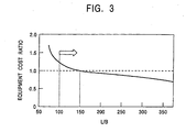
- the equipment cost for the filter was examined by varying L/B using actual equipment for alkali-washing rolled steel sheets.
- the volume of the washing liquid for the steel sheets was approximately 20 m 3 and the circulating flow was 0.2 m 3 /min.
- the results are shown in Fig. 3.
- the residual magnetic flux density B of the permanent magnets and the distance L between the magnets are set to satisfy the relationship: 100 ⁇ B ⁇ L ⁇ 250 ⁇ B
- the iron particle concentration of the fluid at the inlet of the filter was approximately 60 mass ppm to 100 mass ppm.
- the target cleanliness of the circulating fluid is usually 30 mass ppm or less.
- the relationship between the performance (iron particle separation rate ⁇ ) of the filter per unit and the equipment cost for the filter was examined using actual alkali-washing equipment for rolled steel sheets.
- a filter having a circulating flow volume of 0.2 m 3 /min was installed onto the path of the alkaline washing liquid to maintain the iron particle concentration in the alkaline washing liquid at approximately 20 ppm.
- the volume of washing liquid for the steel sheets was approximately 20 m 3
- the average iron particle concentration at the inlet of the filter was approximately 150 mass ppm.
- the results are shown in Fig. 5.
- the equipment cost is compared relative to the equipment cost required at an iron particle separation rate n of 70%, which is defined as 1.0.
- the iron particle separation rate ⁇ of the filter should be 60% or more also from the point of view of equipment cost efficiency.
- Fig. 6 shows the filter length A and the flow speed v of the fluid in the filter.
- the relationship between the filter passage time t and the equipment cost for the filter was examined in actual alkali-washing equipment for rolled steel sheets.
- the volume of the washing liquid for steel sheets was approximately 20 m 3 and the average iron particle concentration at the inlet of the filter was approximately 150 mass ppm in the path for the alkaline washing liquid.
- the filter was installed onto the path in such a manner that the iron particle separation rate ⁇ was 70% at a circulating flow volume of 0.2 m 3 /min and a passage time of 1.0 second so as to maintain the iron particle concentration in the alkaline washing liquid at approximately 20 mass ppm.
- the results are shown in Fig. 8.
- the filter passage time t should be 1.5 seconds or less from the point of view of equipment efficiency.
- the filter passage time of the fluid is limited to the range of 0.5 to 1.5 seconds.
- a steel sheet 7 after rolling was passed through a rough washing tank 8, usually called a dunk-tank, brushed by a first brush scrubber 9, and subjected to main washing in a cleaning tank 10.
- the dunk tank 8 and the cleaning tank 10 were provided with circulating tanks 11 and 12, respectively, and a washing liquid mainly constituting an alkaline washing liquid was circulated using pumps 13 and 14.
- the washing liquid in the circulating tanks 11 and 12 was fed to magnetic filter apparatuses 15 and 16 using pumps 17 and 18, respectively, to attract and separate the iron particles removed from the steel sheets during cleaning.
- the specifications of the magnetic filter apparatus 16 for the circulating tank of the cleaning tank, the filter passage time of the washing liquid, and the iron particle concentration at the inlet are shown in Table 1.
- the iron particle separation rate ⁇ was 60% or more when the magnetic filter apparatus of the present invention is used in the treatment, achieving satisfactory results.
- the examination was also conducted for the cleaning treatment using the magnetic filter apparatus of the present invention as the magnetic filter apparatus 15 for the circulating tank of the dunk tank. The obtained results were satisfactory.
- the present invention yields the highest possible performance from the filter, thereby achieving size reduction with low equipment cost.
Landscapes
- Filtering Materials (AREA)
- Filtration Of Liquid (AREA)
- Water Treatment By Electricity Or Magnetism (AREA)
Abstract
Description


V: volume of the particles,
H: intensity of the magnetic field, and
dH/dx: magnetic gradient (spatial variation in the magnetic field.

wherein, while regulating a filter passage time of the fluid in the range of 0.5 to 1.5 seconds, the permanent magnets are arranged so that the distance L (mm) therebetween in relation to the residual magnetic flux density B (T) of the permanent magnets satisfies the relationship:
A: length of the filter (mm), and
v: flow speed of the fluid in the filter (mm/sec).

Claims (1)
- A magnetic filter apparatus comprising : a container having inlet and outlet for fluid; filter element comprising ferromagnetic material disposed in the container; and permanent magnets for magnetizing the filter element, the permanent magnets being arranged to oppose each other with the container therebetween so as to generate a magnetic line of force in a direction substantially orthogonal to the moving direction of the fluid inside the container,
wherein, while regulating filter passage time of the fluid in the range of 0.5 to 1.5 seconds, the permanent magnets are arranged so that the distance L (mm) therebetween in relation to the residual magnetic flux density B (T) of the permanent magnets satisfies the relationship :
Applications Claiming Priority (3)
| Application Number | Priority Date | Filing Date | Title |
|---|---|---|---|
| JP2000268303 | 2000-09-05 | ||
| JP2000268303A JP2002079011A (en) | 2000-09-05 | 2000-09-05 | Magnetic filter device |
| PCT/JP2001/007645 WO2002020125A1 (en) | 2000-09-05 | 2001-09-04 | Magnetic filter device |
Publications (2)
| Publication Number | Publication Date |
|---|---|
| EP1316348A1 true EP1316348A1 (en) | 2003-06-04 |
| EP1316348A4 EP1316348A4 (en) | 2004-09-08 |
Family
ID=29713499
Family Applications (1)
| Application Number | Title | Priority Date | Filing Date |
|---|---|---|---|
| EP01963413A Withdrawn EP1316348A4 (en) | 2000-09-05 | 2001-09-04 | MAGNETIC FILTERING DEVICE |
Country Status (5)
| Country | Link |
|---|---|
| US (1) | US6649054B2 (en) |
| EP (1) | EP1316348A4 (en) |
| BR (1) | BR0107168A (en) |
| CA (1) | CA2389819A1 (en) |
| WO (1) | WO2002020125A1 (en) |
Families Citing this family (9)
| Publication number | Priority date | Publication date | Assignee | Title |
|---|---|---|---|---|
| US7754264B2 (en) | 2005-01-31 | 2010-07-13 | Nestec S.A. | Process for preparing nutritional products |
| ES2264899B1 (en) | 2005-07-12 | 2008-01-01 | Centro De Investigacion De Rotacion Y Torque Aplicada, S.L. | FILTER TO CAPTURE POLLUTANT EMISSIONS. |
| US20090223602A1 (en) * | 2008-03-06 | 2009-09-10 | Clarence Edward Adkins | Method for magnetizing a filter |
| US8292084B2 (en) | 2009-10-28 | 2012-10-23 | Magnetation, Inc. | Magnetic separator |
| AU2012245294B2 (en) | 2011-04-20 | 2015-10-29 | Magglobal, Llc | Iron ore separation device |
| WO2013077729A1 (en) * | 2011-11-25 | 2013-05-30 | Spiro Enterprises B.V. | Method and magnetic separator for separating magnetic and/or magnetizable particles from a fluid |
| CA2834748C (en) | 2012-11-27 | 2018-03-20 | Bay6 Solutions Inc. | Magnetic filter for a fluid port |
| US9598957B2 (en) | 2013-07-19 | 2017-03-21 | Baker Hughes Incorporated | Switchable magnetic particle filter |
| RU173114U1 (en) * | 2017-03-17 | 2017-08-14 | Ильнур Ильгизарович Амиров | MAGNETIC FLANGE STEEL MAGNETIC FILTER |
Family Cites Families (6)
| Publication number | Priority date | Publication date | Assignee | Title |
|---|---|---|---|---|
| DE2628095C3 (en) * | 1976-06-23 | 1981-08-06 | Siemens AG, 1000 Berlin und 8000 München | Magnetic separation device |
| DE3200988A1 (en) * | 1982-01-14 | 1983-07-28 | Thomas A. Dr. 6900 Heidelberg Reed | METHOD AND DEVICE FOR SEPARATING ORGANIC SUBSTANCES FROM A SUSPENSION OR SOLUTION |
| US4594215A (en) * | 1983-11-04 | 1986-06-10 | Westinghouse Electric Corp. | Augmented high gradient magnetic filter |
| JPS6323707A (en) * | 1986-07-17 | 1988-02-01 | Nippon Steel Corp | Magnetic separator |
| US5200084A (en) * | 1990-09-26 | 1993-04-06 | Immunicon Corporation | Apparatus and methods for magnetic separation |
| JP2728848B2 (en) * | 1993-09-01 | 1998-03-18 | 川崎製鉄株式会社 | Magnetic filter |
-
2001
- 2001-09-04 BR BR0107168-8A patent/BR0107168A/en not_active Application Discontinuation
- 2001-09-04 EP EP01963413A patent/EP1316348A4/en not_active Withdrawn
- 2001-09-04 WO PCT/JP2001/007645 patent/WO2002020125A1/en not_active Ceased
- 2001-09-04 CA CA002389819A patent/CA2389819A1/en not_active Abandoned
- 2001-09-04 US US10/110,309 patent/US6649054B2/en not_active Expired - Fee Related
Also Published As
| Publication number | Publication date |
|---|---|
| BR0107168A (en) | 2002-06-18 |
| EP1316348A4 (en) | 2004-09-08 |
| CA2389819A1 (en) | 2002-03-14 |
| US6649054B2 (en) | 2003-11-18 |
| US20020189990A1 (en) | 2002-12-19 |
| WO2002020125A1 (en) | 2002-03-14 |
Similar Documents
| Publication | Publication Date | Title |
|---|---|---|
| US6649054B2 (en) | Magnetic filter device | |
| JP2000343086A (en) | Ultra high magnetic fluid processing equipment | |
| JP2728848B2 (en) | Magnetic filter | |
| US6139736A (en) | Device for magnetically agglomerating and treating impurities in liquid | |
| KR100697502B1 (en) | Magnetic filter device | |
| KR20020004632A (en) | Magnetic filter for circulating roll milling oil | |
| JP3946287B2 (en) | Pickling method for austenitic stainless steel | |
| US5776258A (en) | Flat-rolled steel strip continuous cleansing methods | |
| CN216737955U (en) | Magnetic disc separating device for hot rolled steel wastewater | |
| CS205014B2 (en) | Method of separating the magnetized particles from the fluid in which are the said particles in suspension and wet magnetic separator for executing the same | |
| JP3323933B2 (en) | Method for removing iron from rolling oil | |
| WO1998011183A1 (en) | Process for removing fine iron containing particles from liquids containing the same | |
| EP0341824A2 (en) | Apparatus for magnetic separation of impurities from fluids | |
| JPH04281807A (en) | Magnetic separator | |
| JP6985692B2 (en) | Chemical cleaning method and particle collector | |
| JP2000300911A (en) | Magnetic fine particle removing method and magnetic fine particle removing apparatus | |
| CN1387958A (en) | Double-frequency pulse and double-vertical ring high-gradient magnetic separator | |
| CA1319113C (en) | Method for washing off magnetically separated particles | |
| CN115246672B (en) | Magnetic medium particle size determination method and coagulation method of magnetic coagulation water treatment technology | |
| JPH05306500A (en) | How to remove sludge from plating solution | |
| JPH10118423A (en) | Strainer equipment | |
| JPH10118422A (en) | Strainer equipment | |
| JP2010058084A (en) | Magnetic separation membrane and magnetic separator | |
| EP1127622A2 (en) | Low intensity magnetic separator | |
| JPH02265689A (en) | Water treatment apparatus |
Legal Events
| Date | Code | Title | Description |
|---|---|---|---|
| PUAI | Public reference made under article 153(3) epc to a published international application that has entered the european phase |
Free format text: ORIGINAL CODE: 0009012 |
|
| 17P | Request for examination filed |
Effective date: 20020521 |
|
| AK | Designated contracting states |
Designated state(s): AT BE CH CY DE DK ES FI FR GB GR IE IT LI LU MC NL PT SE TR |
|
| RAP1 | Party data changed (applicant data changed or rights of an application transferred) |
Owner name: JFE STEEL CORPORATION |
|
| RBV | Designated contracting states (corrected) |
Designated state(s): AT BE CH DE FR GB LI |
|
| A4 | Supplementary search report drawn up and despatched |
Effective date: 20040728 |
|
| RIC1 | Information provided on ipc code assigned before grant |
Ipc: 7B 03C 1/00 B Ipc: 7B 03C 1/28 B Ipc: 7B 01D 35/06 A |
|
| RAP1 | Party data changed (applicant data changed or rights of an application transferred) |
Owner name: JFE ENGINEERING CORPORATION |
|
| 17Q | First examination report despatched |
Effective date: 20050214 |
|
| GRAP | Despatch of communication of intention to grant a patent |
Free format text: ORIGINAL CODE: EPIDOSNIGR1 |
|
| STAA | Information on the status of an ep patent application or granted ep patent |
Free format text: STATUS: THE APPLICATION IS DEEMED TO BE WITHDRAWN |
|
| 18D | Application deemed to be withdrawn |
Effective date: 20051206 |