EP1316004B1 - Vorrichtung zur anzeige der vermeidung einer bodenkollision für ein luftfahrzeug - Google Patents
Vorrichtung zur anzeige der vermeidung einer bodenkollision für ein luftfahrzeug Download PDFInfo
- Publication number
- EP1316004B1 EP1316004B1 EP01969849A EP01969849A EP1316004B1 EP 1316004 B1 EP1316004 B1 EP 1316004B1 EP 01969849 A EP01969849 A EP 01969849A EP 01969849 A EP01969849 A EP 01969849A EP 1316004 B1 EP1316004 B1 EP 1316004B1
- Authority
- EP
- European Patent Office
- Prior art keywords
- aircraft
- terrain
- trajectory
- display
- alarm
- Prior art date
- Legal status (The legal status is an assumption and is not a legal conclusion. Google has not performed a legal analysis and makes no representation as to the accuracy of the status listed.)
- Expired - Lifetime
Links
- 230000000007 visual effect Effects 0.000 title abstract 2
- 230000003068 static effect Effects 0.000 claims abstract description 4
- 239000013598 vector Substances 0.000 claims description 17
- 101000707247 Homo sapiens Protein Shroom3 Proteins 0.000 claims description 12
- 102100031747 Protein Shroom3 Human genes 0.000 claims description 12
- 239000003086 colorant Substances 0.000 claims description 12
- 238000013459 approach Methods 0.000 claims description 9
- 239000007787 solid Substances 0.000 claims description 6
- 230000001960 triggered effect Effects 0.000 claims description 6
- 238000010276 construction Methods 0.000 claims description 4
- 238000009877 rendering Methods 0.000 claims description 4
- 230000007935 neutral effect Effects 0.000 claims description 3
- 230000009467 reduction Effects 0.000 claims description 2
- 238000012795 verification Methods 0.000 claims description 2
- 230000011664 signaling Effects 0.000 abstract description 6
- 238000012800 visualization Methods 0.000 description 46
- 239000000523 sample Substances 0.000 description 19
- 241000897276 Termes Species 0.000 description 9
- 230000006870 function Effects 0.000 description 7
- 230000005764 inhibitory process Effects 0.000 description 7
- 230000001133 acceleration Effects 0.000 description 5
- 238000004364 calculation method Methods 0.000 description 5
- 238000005259 measurement Methods 0.000 description 5
- 238000012986 modification Methods 0.000 description 5
- 230000004048 modification Effects 0.000 description 5
- 230000001681 protective effect Effects 0.000 description 5
- 229920000297 Rayon Polymers 0.000 description 4
- 230000009471 action Effects 0.000 description 4
- 230000007774 longterm Effects 0.000 description 4
- 239000002964 rayon Substances 0.000 description 4
- 238000011144 upstream manufacturing Methods 0.000 description 4
- 238000001514 detection method Methods 0.000 description 3
- 238000000034 method Methods 0.000 description 3
- 230000035484 reaction time Effects 0.000 description 3
- 241001080024 Telles Species 0.000 description 2
- 230000001174 ascending effect Effects 0.000 description 2
- 210000004027 cell Anatomy 0.000 description 2
- 230000003247 decreasing effect Effects 0.000 description 2
- 238000010586 diagram Methods 0.000 description 2
- 235000021183 entrée Nutrition 0.000 description 2
- 230000010354 integration Effects 0.000 description 2
- 230000015654 memory Effects 0.000 description 2
- 230000002265 prevention Effects 0.000 description 2
- 238000012545 processing Methods 0.000 description 2
- 230000000750 progressive effect Effects 0.000 description 2
- 238000011084 recovery Methods 0.000 description 2
- 230000002829 reductive effect Effects 0.000 description 2
- 230000035807 sensation Effects 0.000 description 2
- 230000007704 transition Effects 0.000 description 2
- NQRLWRODNCDUHY-UHFFFAOYSA-N 6-n,6-n,2-trimethylacridine-3,6-diamine Chemical compound C1=C(C)C(N)=CC2=NC3=CC(N(C)C)=CC=C3C=C21 NQRLWRODNCDUHY-UHFFFAOYSA-N 0.000 description 1
- 101100353517 Caenorhabditis elegans pas-2 gene Proteins 0.000 description 1
- 241000196324 Embryophyta Species 0.000 description 1
- 241000872198 Serjania polyphylla Species 0.000 description 1
- 230000006978 adaptation Effects 0.000 description 1
- 230000003466 anti-cipated effect Effects 0.000 description 1
- 230000008859 change Effects 0.000 description 1
- 238000006243 chemical reaction Methods 0.000 description 1
- 230000000295 complement effect Effects 0.000 description 1
- 230000001934 delay Effects 0.000 description 1
- 230000004069 differentiation Effects 0.000 description 1
- 230000008034 disappearance Effects 0.000 description 1
- 230000009977 dual effect Effects 0.000 description 1
- 230000000694 effects Effects 0.000 description 1
- 238000013213 extrapolation Methods 0.000 description 1
- 238000001914 filtration Methods 0.000 description 1
- 230000005484 gravity Effects 0.000 description 1
- 230000012447 hatching Effects 0.000 description 1
- 230000000670 limiting effect Effects 0.000 description 1
- 238000012886 linear function Methods 0.000 description 1
- 230000003071 parasitic effect Effects 0.000 description 1
- 230000036961 partial effect Effects 0.000 description 1
- 230000008447 perception Effects 0.000 description 1
- 230000000384 rearing effect Effects 0.000 description 1
- 238000012360 testing method Methods 0.000 description 1
- 238000012546 transfer Methods 0.000 description 1
- 238000010200 validation analysis Methods 0.000 description 1
- 230000001755 vocal effect Effects 0.000 description 1
- 230000003936 working memory Effects 0.000 description 1
Images


Classifications
-
- G—PHYSICS
- G01—MEASURING; TESTING
- G01C—MEASURING DISTANCES, LEVELS OR BEARINGS; SURVEYING; NAVIGATION; GYROSCOPIC INSTRUMENTS; PHOTOGRAMMETRY OR VIDEOGRAMMETRY
- G01C5/00—Measuring height; Measuring distances transverse to line of sight; Levelling between separated points; Surveyors' levels
- G01C5/005—Measuring height; Measuring distances transverse to line of sight; Levelling between separated points; Surveyors' levels altimeters for aircraft
-
- G—PHYSICS
- G05—CONTROLLING; REGULATING
- G05D—SYSTEMS FOR CONTROLLING OR REGULATING NON-ELECTRIC VARIABLES
- G05D1/00—Control of position, course, altitude or attitude of land, water, air or space vehicles, e.g. using automatic pilots
- G05D1/04—Control of altitude or depth
- G05D1/06—Rate of change of altitude or depth
- G05D1/0607—Rate of change of altitude or depth specially adapted for aircraft
- G05D1/0653—Rate of change of altitude or depth specially adapted for aircraft during a phase of take-off or landing
Definitions
- the invention relates to assistance to air navigation, especially when there is a risk of collision, between an aircraft and the area it flies over.
- GCAS Ground Collision Avoidance System
- GPWS Ground Proximity Warning System
- the ergonomics of visualization is a critical point. It is a matter of equipping as many civil aircraft as possible, and providing the pilot with information that is as clear and easy to interpret as possible, because he may be in a situation that requires his attention elsewhere.
- the present invention improves the situation in this regard.
- the assistance module is arranged to establish a state of landing phase and / or take-off detected; the help module is also arranged to cooperate with the display module in order to selectively inhibit the possible signaling of alerts (in particular pre-alarms, alarms and forecasts on them) on defined parts of the field visualized, landing phase and / or take-off detected.
- the defined portions of the visualized domain include portions adjacent to the predicted trajectory of the aircraft and adjacent portions of an airstrip and / or take-off.
- the display module arranged to cooperate with the help module in order to display a two-dimensional representation of the relief on a visualized domain, is able to inhibit some of the parts of this representation according to of a condition including the fact that the lowest point of each of these parts below a chosen height and that a criterion of proximity between the aircraft and a runway is validated.
- the invention proposes a help module arranged to determine field cuts according to a cutting rule comprising several options.
- the display module is arranged to represent alert lines according to a chosen mode.
- the visualization module is arranged to represent differently different warning zones and to signal alert zones at the edge of the Explored Sector for alert zones detected outside the Explored Sector.
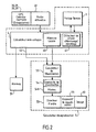
- FIG. 1 we first refer to figures 1 and 2 to describe a first example of non-limiting embodiment of an air navigation aid device to which the invention can be applied.
- a device As described in EP-A-0 565 399 such a device is essentially intended to be installed on board an aircraft, and in particular an airplane.
- This equipment may comprise an inertial or baro-inertial unit 20 or INU, and / or a radionavigation instrument, here a GPS receiver 21 (but it could be an IRS), with its antenna, a radio altimeter 22 , with its antenna, or other onboard navigation sensors.
- INU inertial or baro-inertial unit 20 or INU
- a radionavigation instrument here a GPS receiver 21 (but it could be an IRS), with its antenna, a radio altimeter 22 , with its antenna, or other onboard navigation sensors.
- the inertial unit 20 provides the components of the speed vector (V) of the aircraft and, where appropriate, its acceleration vector ( ⁇ ). We can deduce all or part of the associated characteristic angles (incidence, skid, slope, pitch, course, heel, etc.), or directly collect the values of these angles used internally by the inertial unit. These angular values can be displayed and / or used at the control station. It is the same for example for acceleration, which can be calculated or recalculated from the velocity vector. For altitude, the inertial unit cooperates with a barometric altimeter (not shown), in known manner.
- the GPS receiver 21 provides raw measurements of latitude L1, longitude G1, and altitude Z1, refreshed at a rate p1 of a few seconds to a few minutes.
- the inertial unit 20 provides other measures of latitude L0, longitude G0, and altitude Z0, accurate but drifting in time.
- a block 25 compares the two types of measurement, and validates the quantities L1, G1, Z1, if they are consistent with L0, G0, Z0. Such validation techniques are known.
- Validated measurements L2, G2, Z2 are available at rate p1. But they are refined from the inertial unit at a rate p2 of about one second.
- a block 28 extrapolates the information between the last moment of measurement by the instrument 21 and the current moment (or current) (this extrapolation is useful especially when the information is provided at a rate insufficiently fast).
- the radio altimeter 22 delivers the height above ground, denoted HRS.
- Block 3 contains a field file. Depending on the quantities L and G, we access an extract of this file.
- This extract is a three-dimensional representation of the relief of the region overflown by the aircraft. It is stored in a local memory 40.
- block 4 From this local map, and quantities L, G, Z and HRS, block 4 performs anti-collision calculations, which may be accompanied by terrain avoidance calculations.
- an alarm or alarm 51 is emitted.
- An order director 53 may suggest an avoidance maneuver, if any. This is for the control (or pilot) station.
- the local map can also be used for the generation of a synthetic image 60, on a display device 55.
- EP-A-0 565 399 and EP-A-0 802 469 which also indicate how to reconcile and verify mutually the different information available, especially in vertical.
- EP-A-0 565 399 One of the essential bases of EP-A-0 565 399 is the fact that the Applicant has perceived the possibility of storing on board an aircraft a terrain file capable of representing almost the entire land block, within the contour limit and resolution that is appropriate for the needs of an aircraft .
- the field file can contain precise data concerning the tracks, their geographical location, their designation and their representation for example.
- the landing phase state can be detected by the help module 4 according to the same indices as those of EP-A-0 565 399 .
- SHRM standard lateral avoidance maneuver
- the SHRM avoidance trajectory itself begins at an HRP located on the predicted trajectory. Before this point, two anticipated points HT5 and HT20 are also located on the predicted trajectory, for example respectively at 5 and 20 seconds upstream of the HRP point, taking into account the present speed of the aircraft. A pre-alarm and a "horizontal" alarm are then defined, respectively as soon as the aircraft passes the point HT20, and as soon as it passes the point HT5 (the alarm "naturally" overwrites the pre-alarm).
- CPA collision Prediction and Alerting
- the ultimate aim is to provide the pilot of the aircraft with an alarm signal if the predicted trajectory suggests a certain risk vis-à-vis the surrounding terrain overflown, so that the pilot can initiate an emergency avoidance maneuver of this land with a minimum margin of safety.
- a minimum safety margin is understood both in terms of human reaction time and distance from the terrain avoided.
- neighborhboring flying terrain takes into account not only the terrain directly encountered along the axis of the flight path of the aircraft, but also its adjacent parts.
- the pilot knows that the current trajectory of the aircraft is not likely to touch the terrain, it may be hampered by the issuance of an alert, based on the application of an inadequate avoidance trajectory who touches the relief.
- the information presented such as the representation of the surrounding terrain, the contours defining collision hazards and the representation of the terrain associated with these hazards, prove to provide parasitic information in certain situations that may hinder the pilot's reactions and decisions.
- the visualization as possible speaking for the pilot is necessary in certain situations: terrain overflown particularly rugged; technical problems of the aircraft; take off and landing.
- the pilot could be lacking information on the surrounding dangers if he decides not to follow the indication given following an alarm.
- the invention seeks to overcome these disadvantages, in particular.
- the information to be displayed comes from the local memory 40.
- the take-off and landing phase detector with respect to a track 41 causes, if these phases are detected, visualization modifications described below according to the invention.
- the signaling calculator 5 comprises (or is added to) a visualization calculator 52 able to filter the information according to defined criteria, and to send them to the visualization control 54. Via pilots or "drivers" 541, it transmits information to the order director 53 and especially to the display device 55, which generates a synthetic image 60.
- the defined criteria of filtering are generally geometrical computations corresponding to intersections of surfaces or families of curves. These calculated intersections are assigned attributes indicating their nature, for example: 1000-foot contour line, or "pull-up warning" alarm zone, possibly accompanied by the altitude of the colliding terrain. In general, we know how to make such calculations, as long as the criterion of intersection is defined. Similarly, we know how to convert attributes into a given visualization form, as long as it is defined.
- the viewing device 55 should allow the pilot of the aircraft to apprehend as best as possible the representation of the terrain overflown in three dimensions, from a synthetic image 60 in two dimensions. It is also necessary for the pilot to be able to anticipate, by a horizontal and / or vertical maneuver, possible collisions between the aircraft and the overflown terrain, using a visualization of the possible warning contours in a distinctive form of the contour of the aircraft. ground. Alert contours define either alert lines that mark the geographical boundary of a potential collision hazard and anticipate the occurrence of an alert (pre-alarm or alarm) or alerting terrain zones that appear after the triggering an alert.
- One of the aims of the invention is that these information representations, which are of capital importance to the pilot, are provided in such a way as to be perceived according to their degree of importance in due time.
- the pilot receives the information appropriate to the situation of the flight without being inconvenienced by their unwelcome appearance, profusion or lack of clarity in their visualization.
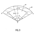
- the image delivered to the pilot is contained in a two-dimensional visualized area. Furthermore, the relief overflown on the one hand, and the possible collision zones between the aircraft and the terrain overflown on the other, are determined according to a three-dimensional Explored Sector, preferably larger (in projection) than the Sector Visualized.
- the figure 3 illustrates the horizontal projection 62 of this Explored Sector that can be viewed on a screen.
- This horizontal projection 62 is delimited by an angular sector of angle V ranging from 1 ° to 360 °, having for vertex the representation of the aircraft A and being closed by a circular arc DE.
- This angular sector is regularly scanned in a rotation of center A, in order to know the terrain overflowing nearby at different times.
- the DE circle marks the limit horizontal exploration beyond which the trajectory of the aircraft is made very random.
- the Explored Sector is divided vertically into adjacent corner sectors ⁇ and the common edge the vertical line passing through the instantaneous position of the aircraft. These angled ⁇ -corner sectors, projected horizontally in radial R, reduce the terrain and alert terrain zones to two dimensions. They also make it possible to display on screen, at a given moment, a selected part of the horizontal projection of the Explored Sector, called Visualized Sector.
- the figure 3 illustrates a Visualized Sector 61 represented on a display device 55, preferably a display screen.
- the domain 61 has a vertex A defining the current position of the aircraft.
- Two segments [AB] and [AC] forming an angle U delimit the Visualized Area within the angular sector of the horizontal projection 62 of the Explored Sector.
- This Visualized Sector 61 is capable of providing the terrain contour (also called background image or background map) and the possible warning contours with the "radial" R, angle ⁇ of value between 0.1 ° and 10 °, preferably 0.35 °.
- the device proposes to represent the Visualized Area according to different scales on the screen.
- the selection of these scales can be done automatically and / or manually.
- the Explored Sector is first defined to detect the terrain surrounding the aircraft in order to offer the pilot a basemap.
- the device thus allows a representation of the relief on screen responding to a staggering altitude and providing a reference point in this gradation such as the current altitude of the aircraft or the altitude of a track.
- the figure 4 presents a vertical section of the relief in a radial of the Explored Sector.
- the relief Rf is represented by a bold line.
- a protective surface Sp which covers the relief Rf is defined by calculation.
- a distance of MTCD separates the relief Rf and the surface Sp representing a minimum margin of safety with the ground, noted MTCD (Minimum Terrain Clearance Distance).
- the representation of the relief is preferably done with the aid of field cuts, determined by parallel surfaces which intercept the representation of the relief. However, unlike contours, these surfaces are not necessarily horizontal or planar.
- a land section is represented by a surface SN3 according to one embodiment of the invention in the figure 4 which will be described later.
- the surfaces SN1 to SN5 are parallel to the surface SN3 and form field cuts.
- the surfaces SN1 to SN5 delimit the ground layers 1, 2, 3, 4 and 5 in a vertical stagger EV defined below.
- the imaginary trajectory of the TA airplane represents a reference surface used to set the upper and lower limits of the terrain layers as shown in Table I of the Annex. These field layer heights are referenced to the reference surface and are differentiated according to colors by means of a "color code".
- the various embodiments of the terrain layers discussed below propose alternatively ground layer heights referred to the ground reference, for example.
- Vertical scaling EV thus defines the relative positions of the terrain layers to a reference surface.
- the terrain layer 3 includes a reference surface referred to as the level 0 reference altitude: the upper limit SN4 has an altitude of +500 feet for example above the reference altitude, and a lower limit corresponding to - min ( 500 feet, MTCD).
- This lower limit of this "ground reference layer” allows the pilot to visualize with reference to the fictitious trajectory of the aircraft TA, the terrain layer corresponding to a height relative -500 feet, or at a minimum safety margin (MTCD), if this relative height MTCD is greater than -500 feet.
- the pilot visualizes the terrain layer with at least a minimum margin in all cases limited to -500 feet under the fictitious flight path of the aircraft.
- the terrain layer 4 comprises an upper limit corresponding to the lower limit of the terrain layer 3 and a lower limit of -1000 feet for example. Apart from these particular layers of terrain and the layer 5 which has no upper limit, the other layers have identical heights, for example 1000 feet.
- the color code is shown in Table II of the Appendix.
- the colors used are yellow colors with very high density, high density and average density respectively assigned to layers 1, 2 and 3, and green colors with low density and very low density respectively assigned to layers 4 and 5.
- the bottom of the screen is black, black is perceived as a non-alerting color.
- the code uses yellow and green colors that fit a wallpaper and have a fairly neutral character.
- the yellow color used relatively dull on a black background, fills the highest layers of terrain. More discreet than the yellow color used, the green color fills the layers of ground under the yellow layers of ground.
- a gradual decrease in the density of the colors used for lower and lower layers of altitudes makes it possible to render on the screen the altitudes of these layers relative to the reference chosen, here compared to the imaginary trajectory TA.
- the pilot's attention is focused on the layers above the fictitious trajectory of the TA airplane.
- the selected gradation of altitude rendering includes a color code based on a neutral color gradient.
- this color code can use different colors and densities of those presented here.
- the code can use only one density and a greater diversity of colors.
- a terrain cut is defined by two connecting surface sections. This will describe the SN3 cut of the figure 4 .
- the first surface section SN3A of the section SN3 is here a sector contained in a half-plane, which follows the predicted trajectory of the aircraft over a distance corresponding to a chosen flight time, to a point L3. Then, the second SN3B surface section is slower than the first, to get closer to the horizontal. In fact, it is currently considered that the second surface section SN3B may be contained in a horizontal half-plane, in the form of a truncated angular sector, which connects with the surface section SN3A.
- vertical EV slice scaling be defined at the SN1B to SN5B surface sections.
- the surfaces SN1B to SN5B may be staggered according to a chosen pitch grid, for example in multiples of 1000 feet.
- the basic size for staggering may be the geographical altitude, or the height on the ground, or even the vertical distance reported to the aircraft.
- the first sectors SN1A to SN5A are of variable axial slope, it is always possible to reduce the distance between two sectors to a vertical difference.
- This fictional trajectory is composed of two surface sections (more generally two surface portions) defining the sectional planes.
- L points correspond to 30 seconds of flight from the current position P of the aircraft, while an alarm is defined by a delay of 5 seconds, and a pre-alarm is defined by a delay of 20 seconds.
- the cuts corresponding to the "first surface section" are made in the direction of the instantaneous axis of the flight. Note that this direction is that of the speed vector of the aircraft, if there is no acceleration component.
- the pilot apprehends the relief following a cutting rule which follows the estimated trajectory of the aircraft downhill then in more horizontal flight.
- This rule provides the pilot with a visualization closer to reality than the old cutting rule that followed the aircraft's instantaneous trajectory. This signaling brings a visualization more speaking and better corresponding to the sensation of the pilot.
- the lower part of the figure 4a shows how the representation of the field cuts is established on a radial R of the Visualized Sector.
- the visualization attributes of the sections are schematically illustrated by gray shading / hatching in the vertical section. They are found on the lower radial, but the attributes of the upper layers mask those of the lower layers. In practice, the visualization is in color, as seen previously.
- each "radial” corresponds to a vertical slice of the Explored Sector 62. It corresponds to it a radial of the Visualized Sector 61, the vertex being the position of the aircraft, illustrated or not on the screen. Sufficient radials of this type are built to fill the Visualized Area. Radials have a pitch of constant ⁇ .
- the pitch of angle p can be variable according to the position of the radials in the Visualized Sector.
- a smaller pitch can be defined around the trajectory of the aircraft to refine the visualization of the relief, on the contrary a larger step avoids too much precision, useless on the edges of the screen.
- the terrain cuts are made along horizontal surfaces having an altitude offset relative to the aircraft of a value that is noted DHA (Delta of Height with respect to the aircraft) of which one formula according to the invention is given by the value of the vertical speed of the aircraft multiplied by a time which may be 30 seconds for example.
- DHA Delta of Height with respect to the aircraft
- the direction of this DHA value is defined in the direction of the vertical component of the instantaneous velocity vector of the aircraft.
- this DHA value simulates a reconciliation at altitude on the screen of the airplane and the terrain visualized, which accentuates the perception of a danger thanks to the basemap when a risk of collision is reported. .
- the result is the same when the plane goes up.
- this second mode returns, for each cut, as SN3, to extend the "second surface section" horizontal SN3B to the left, under the aircraft, while removing the "first oblique" surface section SN3A.
- the value DHA may for example be proportional to the vertical component of the velocity vector, a linear function of this same vertical component of the velocity vector. It will also be noted that in the aircraft configuration of the figure 4 this second mode gives the same result as the first one.
- the terrain cuts are at least partially substantially horizontal surfaces having an altitude offset from the nearest track of a DHP value (Delta of Height with respect to the Track) for a first surface chosen, of a variable value for the other surfaces according to the staggering chosen, for example by using a chosen step grid corresponding to multiples of 1000 feet with reference to the first DHP value surface, and using the same code of color to identify the layers of terrain.
- a DHP value Delta of Height with respect to the Track
- each section a "first surface section” parallel to the predicted trajectory of the aircraft, then a "second surface section” defined as indicated above.
- the pilot apprehends in this way the relief following a cutting rule that offers a visualization of the relief near a track, interesting visualization in case of landing in particular.
- a device can use only one of these modes or several of them selectable automatically and / or manually.
- the help module 4 is arranged to determine cuts of the ground along surfaces defined according to a cutting rule, and the display module 5 is arranged to visualize a map of the cuts of the ground, according to a chosen gradation of altitude rendering.
- the cutting rule comprises the construction of cutting surfaces (SN1, SN2, SN3, SN4, SN5) parallel to each other in a vertical staggering chosen and constituted each of a first surface defined in the direction of the instantaneous trajectory of the aircraft TA, then a second horizontal surface.
- the cutting rule comprises the construction of cutting surfaces (SN1, SN2, SN3, SN4, SN5) parallel to one another in a vertical echeloning EV chosen and constituted each of a horizontal surface.
- the vertical echelon EV chosen is related to the instantaneous position of the aircraft in P.
- the cutting surfaces comprise a portion defined with respect to the instantaneous speed of the aircraft.
- the cutting surfaces each comprise a surface defined in part relative to the direction of the instantaneous velocity vector of the aircraft.
- the vertical EV scaling chosen is related to the track.
- the help module is defined to detect possible collision lines with terrain, called the alert line.
- the figure 4a is a more precise view of the figure 4 .
- the aircraft In this vertical sectional view along a Radial Explored Sector, the aircraft is in a position P at time t0. Its trajectory, here a descent in a straight line, has an angle FPA with the horizontal.
- FPA angle with the horizontal.
- a protective area Sp thin line.
- This surface can be defined in different ways, which is schematized by a minimum margin of safety with the terrain, noted MTCD (Minimum Terrain Clearance Distance).
- a standard avoidance limit trajectory TE also called “feeler” or evasive trajectory, starts from the current position P of the airplane.
- the probe is composed of two parts PM and MN.
- the angle that the segment PM makes with the horizontal is previously chosen to be linked to the instantaneous velocity vector of the aircraft at the point P.
- Its "sensitive” part is a strong ascent, of angle chosen in advance, which begins at a point M of the predicted trajectory.
- the sliding feeler it is possible to move the point M away from the predicted trajectory until it meets the protective surface Sp linked to the relief at a point N, possibly (that is to say, if it is possible in the analyzed space domain).
- the sliding probe scans the entire Explored Sector defining a slick web of feelers. When a vertical avoidance maneuver is no longer possible, the lateral avoidance maneuver as defined above is recommended.
- the meeting points obtained during the scan constitute a first sketch of a potential alert limit line.
- the role of the alert line is to give a forecast of the future (pre-alarms or alarms), as will be seen.
- This warning line is displayed on the navigation screen preferably at most 120 seconds before the limit point at which the aircraft can no longer perform its avoidance trajectory. Beyond, the Applicant currently considers that the prediction of the trajectory of the aircraft is too tainted with errors for the alert line to be relevant.
- the warning line is represented in a continuous line of yellow color of alerting character and different density.
- the assistance module 4 is able to define an evasive trajectory TE, including an extension of the instantaneous trajectory of the aircraft PM followed by a starting point M of a selective component avoidance maneuver, as well as defining a web of evasive trajectories by angular scanning from the first, in principle on both sides thereof.
- the avoidance maneuver comprises a vertical component (SVRM) with a corresponding angular sweep of 0 ° to ⁇ 30 °, or a horizontal component (SHRM) with a corresponding angular sweep of 0 ° to ⁇ 90 °.
- warning lines precede the pre-alarm and the alarm.
- the triggering of an alert also causes the appearance of the location of the representations of relief zones likely to cause a collision.
- the probes scan the Explored Sector to provide the alerting terrain zones, taking into account the minimum margin of safety with the terrain.
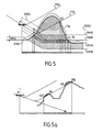
- a frank pre-alarm (without alarm) is shown on the figure 5 .
- the area of land between the two probes and delimited by the surface Sp is considered as a warning zone "warning" projected between the points A1 and A2 on a radial R.
- the figure 5 also shows that the symbolic display of the pre-alarm zone "overwrites" the relief indications.
- the Figure 5A illustrates the detection of two split alert zones.
- the projected warning zone is continuous on a radial R between the point A3 of the first alerting zone and the point A6 of the second alerting zone, in order to equalize the detection of the terrain on a bumpy relief area.
- This leveling of the relief makes it possible to simplify the visualization of the relief for the pilot, and to give him the necessary information without unnecessary details.
- a "warning" alert has been generated.
- the delimitation of a "warning warning zone” differs from the delimitation of a "caution warning zone" as seen previously.
- the area of land on the TPB (between points B1 and B2) and beyond, as well as the area of land between the two probes on the line (B3-B4) and beyond are considered as zone warning "warning".
- the remaining area of land between the two probes is considered a "caution" warning zone.
- the alerting terrain zones are superimposed on the background image representing the relief overflown.
- the terrain zones can be viewed on a blank background image.
- Table III of the appendix shows the probes and the time limits at which certain types of alarm are triggered when the probes are detected of a possible risk of collision.
- the advance warning zones are represented in zones filled with a yellow color of alerting character that can be distinguished from the relatively neutral yellow of the terrain layers; the "alarm" warning zones are represented according to the same texture on the screen, whatever either their type: “avoid ground” and “pitch up”.
- they can be distinguished by two variants of a striking color (alarming): the area of ground justifying the alarm “to pitch up” is for example represented in red 100% united; the field area justifying the "avoid ground” alarm is represented in the same example in alternating 100% red and 100% black circular arc bands, 2 mm wide for each of the colors, for example.
- One variation is to make a red and black checkerboard.
- Another variant proposes to replace the black with another color sharp with the red to produce a certain contrast for the pilot, including white.
- the assistance module 4 is arranged to represent, on the display device 55 and following the triggering of an alert of a certain type, alerting zones of corresponding type delimited according to two types of trajectories.
- TPA and TPB evasive and projected according to radial R.
- the pre-alarm alerting zone zones comprise a zone of ground delimited between the evasive path TPA triggering a meadow. alarm and evasive path TPB triggering an alarm.
- the alarm-type alerting zone zones comprise a terrain zone situated on the evasive trajectory TPA between points (B1) and (B2) as well as beyond, an area of land between the two evasive trajectories TPA and TPB. bounded on its lower edge by the horizontal segment [B4-B3].
- the help module 4 is able to use different textures for the alerting terrain zones of the "terrain avoidance" alarm type and "up" alarm.
- the texture is of solid red color for the alarming zone of the "alarm" alarm type.
- the texture is preferably alternately solid red in color, with another color in the form of concentric circular bands for the "avoidance of terrain" zone.
- the texture is preferably of solid red color, in full alternation, with another color in the form of concentric circular and radial strips for the "avoidance of terrain" type zone.
- the Applicant has tackled the problem of informing the pilot of the information located outside the Visualized Sector.
- a solution can be provided in the manner that will now be described with reference to the figure 7 .
- the Explored Sector is represented at 180 °, ie ⁇ 90 ° on both sides of the instantaneous speed vector of the aircraft.
- the Visualized Sector will generally be narrower, both in angular and radius ("range"), than the Explored Sector.
- warning zones located outside the selected part of the Explored Sector and posted on the edge thereof provide the pilot with the information necessary to decide on a maneuver to be carried out independently of the information recommended on the warning zones located in the part chosen.
- This information provides the pilot with the necessary data to safely decide the flight path of the aircraft to avoid a collision.
- a turn more adapted to the situation than a recommended vertical avoidance maneuver could be considered if no warning zone is displayed at the limit of the selected part of the Explored Sector on the path of the turn.
- the display module 4 is arranged to control a display screen in order to display a portion delimited between ⁇ 45 ° and ⁇ 90 ° depending on the situation of the aircraft of the Explored Sector 61 and said possible terrain zone alerting .
- the display module 5 is arranged to signal differently on the one hand a possible area of alerting land in the delimited part of the Explored Sector 61, on the other hand a possible area of land alerting RE1 located outside this selected part of the Explored Sector 61.
- the display of a possible alerting zone of land situated outside the delimited part of the Explored Sector 61 includes at least one visualization of an area of land alerting on the boundaries of said part of Explored Sector 61.
- the visualization of an alerting zone of land on the boundaries of said delimited portion of the Explored Sector includes a viewing rectangle RE1. More precisely, the viewing rectangle RE1 is of fixed width, of length related to that of the relief of the dangerous surface, of color related to a type of possible collision alert.
- the warning lines are delimited by radial reduced to sections of radial called "pins" E.
- the screen length of these radial sections can take the value e, 5.15 mm for example , 25 lines in the direction of the distance from the representation of the plane in P.
- the radial sections are separated.
- the pin is respectively in the direction of approximation of the representation of the airplane or in the direction of the distance from the representation of the aircraft. 'plane.
- the figure 8a presents three lines of alerts corresponding to the presently preferred example of the invention for the signaling of their radial sections.
- the warning lines L1 and L2 located on the same radial do not fulfill the conditions necessary to be connected by the section T12.
- the warning lines L2 and L3 do not have common radials and each have a respective radial section T2 and T3.
- the alert lines are more easily interpreted by the pilot.
- the distance on the screen between the representation of the aircraft and a line of possible alert causes their juxtaposition or crossing.
- a minimum distance chosen on the screen is imposed between the representation of the aircraft and a warning line. Any alert line LA detected at a distance less than this minimum value is represented by a circular arc LC around the representation of the aircraft.
- this minimum value chosen varies according to the angle of the radial.
- the horizontal angular sector of the probing exploration zone is preferably limited for warning lines to ⁇ 30 ° on either side of the plane's trajectory in a straight line, which makes it possible to limit nuisance alerts in standard approach lanes.
- the help module 4 is able to detect the intersection N of the relief Sp with the evasive trajectory TE and then to cause the selective triggering of alerts according to the estimated duration between the instantaneous position of the aircraft P and the starting point M of an avoidance maneuver.
- the alerts include a pre-alarm triggered for the estimated duration of 20 seconds and an alarm triggered for the estimated duration of 5 seconds.
- the display module 5 is able to represent, according to a selected mode, a single type of alert line at a time, detected by the intersection of the evasive trajectory web with the relief Sp.
- the mode chosen comprises reducing the sections of radial E delimiting said warning lines at their ends.
- the mode chosen comprises a connection of radial sections between two alert lines 1 and 2 each having a radial section located on the same radial; said connection being made after verification of a criterion.
- the criterion comprises the fact that the distance (r) between any two of the stitch points of the same radial does not exceed a pre-defined value, in particular 2 NM.
- the mode chosen comprises the visualization of an alert line LA in a rounded form LC around the aircraft P when a distance of a minimum value predetermined is not respected between: said warning lines LA and the aircraft P displayed on said support.
- the chosen mode comprises an angular sector selected for viewing the alert lines. More precisely, the angular sector chosen is between approximately ⁇ 10 ° and ⁇ 90 °.
- EP-A-0 989 386 proposes to perform a complete inhibition of the CPA mode, which results in a complete inhibition of the alerts. It turned out that this method does not always give satisfaction. The invention overcomes this problem.
- one solution is to partially inhibit the warning lines by their removal around the trajectory of the aircraft along an angular sector of, for example, ⁇ 15 °.
- the neighboring parts of the predicted trajectory of the aircraft TA comprise an angular sector, in the plane of the aircraft trajectory, with an apex angle U of between approximately ⁇ 10 ° and ⁇ 45 ° around the trajectory. of the aircraft predicted from the aircraft during the take-off phase detected. More precisely, the apex angle U is close to ⁇ 15 °.
- warning lines are removed around the flight path of the aircraft following a pre-defined angular sector. Two values of this angular sector are optional depending on the altitude of the aircraft relative to the runway.
- the angular sector of inhibition of the lines warning is for example ⁇ 15 °.
- the angular sector of inhibition of the lines of warning is for example ⁇ 30 °.
- the neighboring parts of the predicted trajectory of the aircraft TA comprise an angular sector, in the plane of the aircraft trajectory, with an apex angle U of between approximately ⁇ 10 ° and ⁇ 45 ° around the plane.
- aircraft axis / runway in the landing phase detected for a criterion of approach to a validated runway.
- This approach criterion includes a specific height of the aircraft above the runway and a selected speed of the airplane.
- the apex angle U is about ⁇ 15 ° for a horizontal distance between the aircraft and the threshold of the runway between about 7 NM and about 15 NM. Specifically, the apex angle U is about ⁇ 30 ° for a horizontal distance between the aircraft and the runway threshold between about 2.7 NM and about 7 NM.
- the invention proposes a black uniformization of the only layers of terrain near the track according to a certain criterion.
- the criterion proposes that the lowest point of the considered layer should be below a predefined height relative to the track.
- the display module 5, arranged to cooperate with the help module 4 in order to display a two-dimensional representation of the relief on a visualized domain 61 is able to inhibit some of the parts of this representation as a function of a condition including the fact that the lowest point of each of these parts is below a chosen height and that a criterion of proximity between the aircraft and a track is validated. More specifically, said proximity criterion includes the fact that the height of the aircraft relative to the level of the nearest runway is less than a pre-defined threshold and the fact that the horizontal distance between the aircraft and the runway the most close to or below a pre-defined threshold.
- help module and a display module that cooperate to achieve together different aspects of the invention.
- distribution of functions between the help module and the display module may vary according to the realization of choices within the scope of the skilled person. All or almost all of the functions can be implemented in the help module or the visualization module, which can be reduced to the screen.
- a product according to the invention does not necessarily contain the screen.
- help and visualization modules are considered as virtual objects not limited to only the elements constituting them in the description.
- the invention is not limited to a device applicable only to aircraft.
- the navigation assistance proposed according to the invention can be integrated with the equipment of other helicopter type aircraft by making some adaptations to the scope of the skilled person.
- the altitude reference 0 corresponds to the fictitious trajectory of the aircraft in the presently preferred example of the invention.
- TABLE II Number of the layer of land Color Density 1 Yellow Very high density 2 Yellow High density 3 Yellow Average density 4 Green Low density 5 Green Very low density feeler Deadline alert (maneuver) (Seconds) English French SVRM 5 pull-up Rearing SVRM 20 bail Pre-Alarm SHRM 5 avoid terrain avoid ground SHRM 20 bail Pre-Alarm Criterion Viewing ALT> Ta1 no alerts line displayed Ta1>ALT> Ta2 pre-alarm alert line displayed Ta2>ALT> Ta3 alarm alert line displayed Ta3> ALT no alerts line displayed
Landscapes
- Engineering & Computer Science (AREA)
- Radar, Positioning & Navigation (AREA)
- Remote Sensing (AREA)
- Physics & Mathematics (AREA)
- General Physics & Mathematics (AREA)
- Aviation & Aerospace Engineering (AREA)
- Automation & Control Theory (AREA)
- Traffic Control Systems (AREA)
- Navigation (AREA)
- Emergency Alarm Devices (AREA)
Claims (48)
- Hilfsvorrichtung zur Luftnavigation, mit der ein Luftfahrzeug ausgestattet wird und die Folgendes umfasst:- einen Eingang (2) zum Empfangen von statischen und dynamischen Parametern des Luftfahrzeugs,- ein Hilfsmodul (4), das zum Benutzen der Parameter und wenigstens einer Datenbank des Reliefs des überflogenen Geländes (3) ausgelegt ist, um Reliefinformationen über einen untersuchten dreidimensionalen Bereich daraus abzurufen, definiert in Abhängigkeit von der Flugbahn des Luftfahrzeugs, und um eventuelle Warninformationen (51; 42) zu entwickeln, die einem Kollisionsrisiko zwischen dem Luftfahrzeug und dem Relief entsprechen, in Abhängigkeit von wenigstens einer vorhergesagten Flugbahn des Luftfahrzeugs, und- ein Anzeigemodul (5), das zum Zusammenwirken mit dem Hilfsmodul (4) ausgelegt ist, um eine zweidimensionale Darstellung des Reliefs auf einem Anzeigebereich anzuzeigen (55) und dort eine Signalisierung eventueller Alarmierungen einzufügen,dadurch gekennzeichnet, dass das Hilfsmodul (4) ausgelegt ist, um einen erkannten Lande- und/oder Startphasenzustand (41) zu bestimmen und mit dem Anzeigemodul (5) zusammenzuwirken, um in der erkannten Lande- und/oder Startphase selektiv die eventuelle Signalisierung von Alarmierungen auf definierten und begrenzten Teilen des angezeigten Bereichs zu sperren, wobei die definierten und begrenzten Teile des angezeigten Bereichs (61) benachbarte Teile der vorhergesagten Flugbahn des Luftfahrzeugs umfassen.
- Vorrichtung nach Anspruch 1, dadurch gekennzeichnet, dass die Alarmierungen Voralarme und Alarme umfassen.
- Vorrichtung nach Anspruch 2, dadurch gekennzeichnet, dass die Alarmierungen prädiktive Indikationen über zukünftige Alarme oder Voralarme umfassen.
- Vorrichtung nach Anspruch 3, dadurch gekennzeichnet, dass die Nachbarteile der vorgesagten Flugbahn des Luftfahrzeugs (TA) einen Winkelsektor, in der Ebene der Flugbahn des Luftfahrzeugs, eines Scheitelwinkels (U) zwischen etwa ± 10° und ± 45° um die vorgesagte Flugbahn des Luftfahrzeugs in der erkannten Startphase umfassen.
- Vorrichtung nach Anspruch 4, dadurch gekennzeichnet, dass der Scheitelwinkel (U) um ± 15° liegt.
- Vorrichtung nach einem der Ansprüche 4 bis 5, dadurch gekennzeichnet, dass die Nachbarteile der vorgesagten Flugbahn des Luftfahrzeugs (TA) einen Winkelsektor, in der Ebene der Flugbahn des Luftfahrzeugs, eines Scheitelwinkels (U) zwischen etwa ± 10° und ± 45° um die Achse Luftfahrzeug/Landebahn in der erkannten Landephase für ein Anflugkriterium einer validierten Landebahn umfassen.
- Vorrichtung nach Anspruch 6, dadurch gekennzeichnet, dass das Anflugkriterium eine vorbestimmte Höhe des Flugzeugs über der Landebahn und eine gewählte Geschwindigkeit des Flugzeugs umfasst.
- Vorrichtung nach den Ansprüchen 6 und 7, dadurch gekennzeichnet, dass der Scheitelwinkel (U) etwa ± 15° für eine horizontale Distanz zwischen dem Flugzeug und der Schwelle der Landebahn zwischen etwa 7 NM und etwa 15 NM liegt.
- Vorrichtung nach einem der Ansprüche 6 bis 8, dadurch gekennzeichnet, dass der Scheitelwinkel (U) etwa ± 30° für eine horizontale Distanz zwischen dem Flugzeug und der Schwelle der Landebahn zwischen etwa 2,7 NM und etwa 7 NM beträgt.
- Vorrichtung nach Anspruch 1, dadurch gekennzeichnet, dass die definierten Teile des angezeigten Bereichs (61) Nachbarteile einer angezeigten Start-/Landebahn umfassen.
- Vorrichtung nach den Ansprüchen 1 bis 10, wobei das Anzeigemodul (5) ausgelegt ist, um mit dem Hilfsmodul (4) zusammenzuwirken, um eine zweidimensionale Darstellung des Reliefs in einem angezeigten Bereich (61) anzuzeigen (55), dadurch gekennzeichnet, dass das Anzeigemodul (5), das zum Zusammenwirken mit dem Hilfsmodul (4) ausgelegt ist, bestimmte Teile dieser Darstellung in Abhängigkeit von einer Bedingung sperren kann, die die Tatsache beinhaltet, dass der tiefste Punkt jedes dieser Teile unterhalb einer gewählten Höhe ist und dass ein Nähekriterium zwischen dem Luftfahrzeug und einer Start-/Landebahn validiert wird.
- Vorrichtung nach Anspruch 11, dadurch gekennzeichnet, dass das Nähekriterium die Tatsache beinhaltet, dass die Höhe des Luftfahrzeugs in Bezug auf das Niveau der nächstliegenden Landebahn geringer ist als ein vordefinierter Schwellenwert, und die Tatsache, dass die horizontale Distanz zwischen dem Luftfahrzeug und der nächstliegenden Start-/Landebahn geringer ist als ein vordefinierter Schwellenwert.
- Vorrichtung nach den Ansprüchen 1 bis 12, dadurch gekennzeichnet, dass das Anzeigemodul (5) ausgelegt ist, um mit dem Hilfsmodul (4) zusammenzuwirken, um die Start-/Landebahn in einer bestimmten Farbe in der Lande-/Startphase des Luftfahrzeugs anzuzeigen (55).
- Vorrichtung nach einem der vorherigen Ansprüche, dadurch gekennzeichnet, dass das Hilfsmodul (4) ausgelegt ist, um Geländeschnitte über definierte Flächen gemäß einer Schnittregel zu ermitteln, und dadurch, dass das Anzeigemodul (5) ausgelegt ist, um eine Geländeschnittkarte gemäß einer gewählten Gradierung zum Rendern von Höhen anzuzeigen.
- Vorrichtung nach Anspruch 14, dadurch gekennzeichnet, dass die Schnittregel die Konstruktion von zueinander parallelen Schnittflächen (SN1, SN2, SN3, SN4, SN5) gemäß einem gewählten vertikalen Maßstab umfasst, die jeweils von einer gemäß der Richtung der momentanen Flugbahn des Luftfahrzeugs (TA) definierten ersten Fläche und dann einer zweiten horizontalen Fläche gebildet werden.
- Vorrichtung nach Anspruch 14, dadurch gekennzeichnet, dass die Schnittregel die Konstruktion von zueinander parallelen Schnittflächen (SN1, SN2, SN3, SN4, SN5) gemäß einem gewählten vertikalen Maßstab (EV) umfasst, die jeweils von einer horizontalen Fläche gebildet werden.
- Vorrichtung nach einem der Ansprüche 14 bis 16, dadurch gekennzeichnet, dass der gewählte vertikale Maßstab (EV) auf die momentane Position (P) des Luftfahrzeugs bezogen wird.
- Vorrichtung nach einem der Ansprüche 14 bis 17, dadurch gekennzeichnet, dass die Schnittflächen einen Teil umfassen, der in Bezug auf die momentane Geschwindigkeit des Luftfahrzeugs definiert wird.
- Vorrichtung nach einem der Ansprüche 14 bis 18, dadurch gekennzeichnet, dass die Schnittflächen jeweils eine Fläche umfassen, die teilweise in Bezug auf die Richtung des momentanen Geschwindigkeitsvektors des Luftfahrzeugs definiert wird.
- Vorrichtung nach einem der Ansprüche 14 bis 16, dadurch gekennzeichnet, dass der gewählte vertikale Maßstab (EV) auf die Start-/Landebahn bezogen wird.
- Vorrichtung nach den Ansprüchen 14 bis 20, dadurch gekennzeichnet, dass die gewählte Gradierung zum Rendern der Höhe einen Farbcode umfasst, der auf einer Abstufung von neutralen Farben basiert.
- Vorrichtung nach einem der vorherigen Ansprüche, dadurch gekennzeichnet, dass das Hilfsmodul (4) eine Ausweichflugbahn (TE) definieren kann, die eine Verlängerung der momentanen Flugbahn des Luftfahrzeugs (PM) gefolgt von einem Startpunkt (M) eines Umgehungsmanövers mit einer gewählten Komponente umfasst, sowie eine Schicht von Ausweichflugbahnen durch winkelmäßiges Abtasten von der ersten Ausweichflugbahn definieren kann.
- Vorrichtung nach Anspruch 22, dadurch gekennzeichnet, dass das Umgehungsmanöver eine vertikale Komponente (SVRM) umfasst.
- Vorrichtung nach Anspruch 22, dadurch gekennzeichnet, dass das Umgehungsmanöver eine horizontale Komponente (SHRM) umfasst.
- Vorrichtung nach einem der Ansprüche 22 bis 24, dadurch gekennzeichnet, dass das Hilfsmodul (4) den Schnittpunkt des Reliefs (Sp) mit der Schicht von Ausweichflugbahnen (TE) erkennen kann, um dann ein selektives Auslösen von Alarmierungen je nach der geschätzten Dauer zwischen der momentanen Position (P) des Luftfahrzeugs und dem Startpunkt (M) eines Ausweichmanövers zu bewirken.
- Vorrichtung nach einem der Ansprüche 20 bis 25, dadurch gekennzeichnet, dass die Alarmierungen einen Voralarm, der für die geschätzte Dauer von 20 Sekunden ausgelöst wird, und einen Alarm umfassen, der für die geschätzte Dauer von 5 Sekunden ausgelöst wird.
- Vorrichtung nach einem der Ansprüche 20 bis 26, dadurch gekennzeichnet, dass die Alarmierungen prädiktive Indikationen über zukünftige Alarme oder Voralarme umfassen, Alarmierungslinien genannt.
- Vorrichtung nach einem der Ansprüche 22 bis 27, dadurch gekennzeichnet, dass das Anzeigemodul (5) je nach einem gewählten Modus jeweils einen Alarmierungslinientyp darstellen kann.
- Vorrichtung nach Anspruch 28, dadurch gekennzeichnet, dass der gewählte Modus die Reduzierung von Radialabschnitten (E) umfasst, die die Alarmierungslinien an ihren Enden begrenzen.
- Vorrichtung nach den Ansprüchen 28 und 29, dadurch gekennzeichnet, dass der gewählte Modus einen Anschluss von Radialabschnitten zwischen zwei Alarmierungslinien (L'1 und L'2) umfasst, die jeweils einen Radialabschnitt umfassen, der sich auf einem selben Radius befindet, wobei der Anschluss nach der Verifizierung eines Kriteriums erfolgt.
- Vorrichtung nach einem der Ansprüche 28 bis 30, dadurch gekennzeichnet, dass das Kriterium die Tatsache beinhaltet, dass die Distanz (r) zwischen zwei beliebigen Punkten des Abschnitts eines selben Radius einen vordefinierten Wert, insbesondere 2 NM, nicht übersteigt.
- Vorrichtung nach einem der Ansprüche 28 bis 31, dadurch gekennzeichnet, dass der gewählte Modus die Anzeige einer Alarmierungslinie (LA) in einer abgerundeten Form (LC) um das Luftfahrzeug P umfasst, wenn eine Distanz mit einem vorbestimmten Mindestwert zwischen den Alarmierungslinien (LA) und dem auf dem Träger angezeigten Luftfahrzeug (P) nicht eingehalten wird.
- Vorrichtung nach einem der Ansprüche 28 bis 32, dadurch gekennzeichnet, dass der gewählte Modus einen gewählten Winkelsektor für die Anzeige der Alarmierungslinien umfasst.
- Vorrichtung nach Anspruch 33, dadurch gekennzeichnet, dass der gewählte Winkelsektor zwischen etwa ± 10° und ± 90° liegt.
- Vorrichtung nach einem der vorherigen Ansprüche, dadurch gekennzeichnet, dass das Hilfsmodul (4) ausgelegt ist, um auf der Anzeigevorrichtung (55) und nach dem Auslösen einer Alarmierung eines bestimmten Typs Alarmierungsgeländezonen des entsprechenden Typs darzustellen, die nach zwei Ausweichflugbahntypen (TPA und TPB) begrenzt und entlang den Radien (R) projiziert werden.
- Vorrichtung nach Anspruch 35, dadurch gekennzeichnet, dass die Alarmierungsgeländezonen des Voralarmtyps eine Geländezone beinhalten, die zwischen der einen Voralarm auslösenden Ausweichflugbahn (TPA) und der einen Alarm auslösenden Ausweichflugbahn (TPB) begrenzt wird.
- Vorrichtung nach einem der Ansprüche 35 und 36, dadurch gekennzeichnet, dass die Alarmierungsgeländezonen des Alarmtyps eine Geländezone, die sich auf der Ausweichflugbahn (TA) zwischen den Punkten (B 1) und (B2) sowie darüber hinaus befinden, und eine Geländezone beinhalten, die sich zwischen den beiden Ausweichflugbahnen (TPA) und (TPB) befindet, die am unteren Rand durch das horizontale Segment [B4-B3] begrenzt wird.
- Vorrichtung nach einem der Ansprüche 35 bis 37, dadurch gekennzeichnet, dass das Hilfsmodul (4) unterschiedliche Texturen für die Alarmgeländezonen des Alarmtyps "Geländeumgehung" und des Alarmtyps "Steigflug" nutzen kann.
- Vorrichtung nach Anspruch 38, dadurch gekennzeichnet, dass die Textur eine durchgehend rote Farbe für die Alarmierungsgeländezone des Alarmtyps "Steigflug" hat.
- Vorrichtung nach einem der Ansprüche 38 und 39, dadurch gekennzeichnet, dass die Textur vorzugsweise von einer durchgehend roten Farbe ist, die sich mit einer anderen Farbe in Form von konzentrischen kreisförmigen Streifen für die Zone des Alarmtyps "Geländeumgehung" abwechselt.
- Vorrichtung nach einem der Ansprüche 38 und 39, dadurch gekennzeichnet, dass die Textur vorzugsweise von einer durchgehend roten Farbe ist, die im doppelten Wechsel mit einer anderen Farbe in Form von radialen und konzentrischen kreisförmigen Streifen für die Zone des Alarmtyps "Geländeumgehung" abwechselt.
- Vorrichtung nach einem der Ansprüche 40 und 41, dadurch gekennzeichnet, dass die andere Farbe vorzugsweise Schwarz ist.
- Vorrichtung nach einem der Ansprüche 40 und 41, dadurch gekennzeichnet, dass die andere Farbe vorzugsweise Weiß ist.
- Vorrichtung nach einem der vorherigen Ansprüche, dadurch gekennzeichnet, dass das Anzeigemodul (5) ausgelegt ist, um einen Anzeigeschirm zu steuern, damit er einen Teil anzeigt, der zwischen ± 45° und ± 90° in Abhängigkeit vom Ort des Flugzeugs im untersuchten Sektor (61) und den eventuellen Alarmierungsgeländezonen begrenzt wird.
- Vorrichtung nach Anspruch 44, dadurch gekennzeichnet, dass das Anzeigemodul (5) ausgelegt ist, um eine eventuelle Alarmierungsgeländezone in dem begrenzten Teil des untersuchten Sektors (61) einerseits und eine eventuelle Alarmierungsgeländezone (RE1) andererseits unterschiedlich zu signalieren, die sich außerhalb dieses gewählten Teils des untersuchten Sektors (61) befindet.
- Vorrichtung nach einem der Ansprüche 44 und 45, dadurch gekennzeichnet, dass die Anzeige einer eventuellen Alarmierungsgeländezone, die sich außerhalb des begrenzten Teils des untersuchten Sektors (61) befindet, wenigstens eine Anzeige einer Alarmierungsgeländezone auf den Grenzen des Teils des untersuchten Sektors (61) beinhaltet.
- Vorrichtung nach einem der Ansprüche 44 bis 46, dadurch gekennzeichnet, dass die Anzeige einer Alarmierungsgeländezone auf den Grenzen des begrenzten Teils des untersuchten Sektors ein Anzeigerechteck (RE1) beinhaltet.
- Vorrichtung nach Anspruch 47, dadurch gekennzeichnet, dass das Anzeigerechteck (RE1) eine feste Breite, eine Länge, die mit der des Reliefs der gefährlichen Fläche assoziiert ist, und eine Farbe hat, die mit einem Alarmierungstyp "mögliche Kollision" verbunden ist.
Applications Claiming Priority (3)
| Application Number | Priority Date | Filing Date | Title |
|---|---|---|---|
| FR0011491 | 2000-09-08 | ||
| FR0011491A FR2813963B1 (fr) | 2000-09-08 | 2000-09-08 | Perfectionnements a la visualisation de dispositifs d'anti collision terrain pour aeronef |
| PCT/FR2001/002727 WO2002021229A2 (fr) | 2000-09-08 | 2001-09-03 | Visualisation de dispositifs d'anti-collision terrain pour aeronef |
Publications (2)
| Publication Number | Publication Date |
|---|---|
| EP1316004A2 EP1316004A2 (de) | 2003-06-04 |
| EP1316004B1 true EP1316004B1 (de) | 2011-12-14 |
Family
ID=8854120
Family Applications (1)
| Application Number | Title | Priority Date | Filing Date |
|---|---|---|---|
| EP01969849A Expired - Lifetime EP1316004B1 (de) | 2000-09-08 | 2001-09-03 | Vorrichtung zur anzeige der vermeidung einer bodenkollision für ein luftfahrzeug |
Country Status (5)
| Country | Link |
|---|---|
| US (1) | US20030107499A1 (de) |
| EP (1) | EP1316004B1 (de) |
| CA (1) | CA2390230A1 (de) |
| FR (1) | FR2813963B1 (de) |
| WO (1) | WO2002021229A2 (de) |
Cited By (1)
| Publication number | Priority date | Publication date | Assignee | Title |
|---|---|---|---|---|
| US10228692B2 (en) | 2017-03-27 | 2019-03-12 | Gulfstream Aerospace Corporation | Aircraft flight envelope protection and recovery autopilot |
Families Citing this family (68)
| Publication number | Priority date | Publication date | Assignee | Title |
|---|---|---|---|---|
| US7587278B2 (en) * | 2002-05-15 | 2009-09-08 | Honeywell International Inc. | Ground operations and advanced runway awareness and advisory system |
| US7117089B2 (en) * | 2001-03-06 | 2006-10-03 | Honeywell International Inc. | Ground runway awareness and advisory system |
| US8145367B2 (en) | 2001-03-06 | 2012-03-27 | Honeywell International Inc. | Closed airport surface alerting system |
| US7079951B2 (en) * | 2002-05-15 | 2006-07-18 | Honeywell International Inc. | Ground operations and imminent landing runway selection |
| DE10226885A1 (de) * | 2002-06-17 | 2004-01-08 | Herman/Becker Automotive Systems (Xsys Division) Gmbh | Verfahren und Fahrerinformationssystem zum Darstellen eines ausgewählten Kartenausschnitts |
| FR2842594B1 (fr) * | 2002-07-19 | 2004-09-10 | Thales Sa | Procede et dispositif d'aide a la navigation d'un areonef |
| FR2848661B1 (fr) * | 2002-12-13 | 2005-03-04 | Thales Sa | Equipement anticollision terrain embarque a bord d'aeronef avec aide au retour en vol normal |
| FR2848662B1 (fr) * | 2002-12-17 | 2005-03-04 | Thales Sa | Dispositif d'affichage pour equipement anticollision terrain embarque a bord d'aeronef |
| US7386373B1 (en) * | 2003-01-07 | 2008-06-10 | Garmin International, Inc. | System, method and apparatus for searching geographic area using prioritized spatial order |
| FR2854129B1 (fr) * | 2003-04-28 | 2007-06-01 | Airbus France | Dispositif d'affichage dans un cockpit d'aeronef d'informations concernant le trafic environnant |
| US7046259B2 (en) * | 2003-04-30 | 2006-05-16 | The Boeing Company | Method and system for presenting different views to passengers in a moving vehicle |
| US7088310B2 (en) * | 2003-04-30 | 2006-08-08 | The Boeing Company | Method and system for presenting an image of an external view in a moving vehicle |
| US6866225B2 (en) * | 2003-04-30 | 2005-03-15 | The Boeing Company | Method and system for presenting moving simulated images in a moving vehicle |
| FR2864270B1 (fr) * | 2003-12-19 | 2006-02-24 | Thales Sa | Dispositif avance d'anti-collision terrain |
| FR2867559B1 (fr) * | 2004-03-12 | 2006-05-26 | Thales Sa | Dispositif d'affichage de carte topographique pour aeronef |
| FR2867851B1 (fr) * | 2004-03-19 | 2006-05-26 | Thales Sa | Procede de reperage, sur une carte, de points difficiles d'acces |
| FR2870604B1 (fr) * | 2004-05-18 | 2006-08-11 | Airbus France Sas | Procede et dispositif de securisation d'un vol a basse altitude d'un aeronef |
| FR2870607B1 (fr) | 2004-05-18 | 2006-08-11 | Airbus France Sas | Procede et dispositif pour construire une trajectoire de vol a basse altitude destinee a etre suivie par un aeronef |
| FR2875916B1 (fr) * | 2004-09-28 | 2015-06-26 | Eurocopter France | Procede et dispositif d'aide au pilotage d'un aeronef a voilure tournante au voisinage d'un point de pose ou de decollage |
| FR2875901B1 (fr) * | 2004-09-28 | 2006-12-08 | Eurocopter France | Systeme embarque de construction d'une route aerienne |
| FR2876483B1 (fr) * | 2004-10-08 | 2007-07-20 | Airbus France Sas | Procede et systeme d'evitement pour un aeronef |
| FR2877721B1 (fr) * | 2004-11-10 | 2007-01-19 | Thales Sa | Dispositif de representation cartographique des vitesses verticales minimales |
| WO2006132422A1 (ja) * | 2005-06-08 | 2006-12-14 | Toshio Tuyuki | 航行システム |
| FR2889342B1 (fr) * | 2005-07-26 | 2010-11-19 | Airbus France | Procede et dispositif de detection d'un risque de collision d'un aeronef avec le terrain environnant |
| FR2891645B1 (fr) | 2005-09-30 | 2007-12-14 | Thales Sa | Procede et dispositif d'evaluation de la liceite de la situation d'un mobile sur la surface d'un aeroport. |
| FR2891644B1 (fr) * | 2005-09-30 | 2011-03-11 | Thales Sa | Procede et dispositif d'aide pour la circulation d'un mobile a la surface d'un aeroport. |
| FR2893174B1 (fr) * | 2005-11-10 | 2008-01-25 | Thales Sa | Procede d'optimisation de l'affichage de donnees relatives aux risques lies aux obstacles |
| FR2893146B1 (fr) * | 2005-11-10 | 2008-01-25 | Thales Sa | Systeme d'evitement de terrain pour aeronefs de transport |
| FR2895098B1 (fr) | 2005-12-20 | 2008-06-20 | Thales Sa | Systeme embarque de prevention des collisions d'un aeronef avec le terrain |
| FR2895794B1 (fr) * | 2006-01-05 | 2008-02-15 | Airbus France Sas | Procede et dispositif d'assistance au pilotage d'un aeronef en vol libre. |
| FR2897972B1 (fr) * | 2006-02-27 | 2008-05-09 | Airbus France Sas | Systeme de visualisation d'images pour passagers d'un aeronef et aeronef comportant un tel systeme |
| FR2897839B1 (fr) | 2006-02-27 | 2009-01-23 | Airbus France Sas | Procede et dispositif d'ajustememnt automatique d'une image d'un ecran de navigation d'aeronef. |
| FR2905756B1 (fr) | 2006-09-12 | 2009-11-27 | Thales Sa | Procede et dispositif pour aeronef,d'evitement des collisions avec le terrain |
| US8373579B2 (en) * | 2006-12-06 | 2013-02-12 | Universal Avionics Systems Corporation | Aircraft ground maneuvering monitoring system |
| US7598888B2 (en) | 2006-12-08 | 2009-10-06 | Sikorsky Aircraft Corporation | Rotary wing aircraft proximity warning system with a geographically based avoidance system |
| FR2912502B1 (fr) * | 2007-02-13 | 2009-03-27 | Thales Sa | Procede de traitement temps reel de donnees topographiques dans un aeronef,en vue de leur affichage |
| FR2913800B1 (fr) | 2007-03-13 | 2010-08-20 | Thales Sa | Dispositifs et procedes de filtrage d'alertes anti-collision de terrain et d'obstacles pour aeronef |
| FR2913781B1 (fr) * | 2007-03-13 | 2009-04-24 | Thales Sa | Procede de reduction des nuisances d'alerte anticollision avec des obstacles pour aeronef |
| FR2916568B1 (fr) * | 2007-05-25 | 2014-11-21 | Thales Sa | Dispositif de visualisation pour aeronef comprenant des moyens d'affichage d'une symbologie de navigation dediee a l'evitement d'obstacles. |
| US8019491B1 (en) * | 2007-09-27 | 2011-09-13 | Rockwell Collins, Inc. | Generating lateral guidance image data in a terrain awareness and warning system |
| BRPI0912689B1 (pt) | 2008-05-14 | 2019-07-09 | Elbit Systems Ltd. | Aparelho e método para observação adiante de evitação de terreno (flta) em uma aeronave, método para uma fase de planejamento, método para evitação de terreno de observação adiante (flta) em uma aeronave |
| FR2932306B1 (fr) * | 2008-06-10 | 2010-08-20 | Thales Sa | Procede et dispositif d'aide a la navigation pour un aeronef vis-a-vis des obstacles. |
| FR2932279B1 (fr) | 2008-06-10 | 2011-08-19 | Thales Sa | Dispositif et procede de surveillance des obstructions dans l'environnement proche d'un aeronef. |
| FR2932919B1 (fr) | 2008-06-24 | 2010-08-20 | Eurocopter France | Adaptation d'alertes de terrain selectives, en fonction la manoeuvrabilite instantanee d'un giravion |
| FR2935481B1 (fr) | 2008-09-02 | 2011-02-11 | Thales Sa | Procede de surveillance des zones atmospheriques pour un aeronef |
| FR2935824B1 (fr) * | 2008-09-09 | 2010-09-03 | Thales Sa | Dispositif de visualisation pour aeronef comprenant des moyens d'affichage d'aeronefs presentant un risque de collision |
| FR2936344B1 (fr) * | 2008-09-23 | 2011-10-21 | Airbus France | Procede et dispositif pour la prevention des alertes inutiles engendrees par un systeme anticollision monte a bord d'un avion |
| FR2946780B1 (fr) * | 2009-06-12 | 2011-07-15 | Thales Sa | Procede et dispositif d'affichage des limites de marges de vol pour un aeronef |
| FR2949569B1 (fr) * | 2009-09-01 | 2011-08-19 | Thales Sa | Systeme d'aide a la navigation a affichage 3d et son procede d'affichage |
| US8886369B2 (en) * | 2010-02-11 | 2014-11-11 | The Boeing Company | Vertical situation awareness system for aircraft |
| FR2956491B1 (fr) * | 2010-02-15 | 2012-09-28 | Airbus Operations Sas | Procede et dispositif de surveillance de hauteurs radioaltimetriques d'un aeronef. |
| FR2957447B1 (fr) * | 2010-03-15 | 2012-10-26 | Eurocopter France | Procede et dispositif pour voler a l'aide d'un aeronef a basse altitude de maniere securisee |
| US8638240B2 (en) * | 2011-02-07 | 2014-01-28 | Honeywell International Inc. | Airport taxiway collision alerting system |
| US20130271300A1 (en) * | 2012-04-12 | 2013-10-17 | Honeywell International Inc. | Systems and methods for improving runway awareness with takeoff and landing performance data |
| US9092976B2 (en) * | 2012-09-14 | 2015-07-28 | Honeywell International Inc. | Systems and methods for providing runway-entry awareness and alerting |
| US9168859B2 (en) | 2013-02-25 | 2015-10-27 | Honeywell International Inc. | System and method for displaying visual flight reference points |
| FR3008530B1 (fr) | 2013-07-10 | 2015-07-17 | Eurocopter France | Procede et dispositif d'emission d'alertes pour l'evitement de terrain par un aeronef a voilure tournante |
| US20160085238A1 (en) * | 2013-08-30 | 2016-03-24 | Insitu, Inc. | Display of terrain along flight paths |
| US10347142B2 (en) | 2014-11-05 | 2019-07-09 | Honeywell International Inc. | Air traffic system using procedural trajectory prediction |
| EP3271743A4 (de) * | 2015-03-17 | 2018-12-05 | Sikorsky Aircraft Corporation | Bahnregler eines fahrzeugs |
| EP3286086A4 (de) * | 2015-04-22 | 2018-10-24 | Astronautics Corporation Of America | Elektronische anzeige von kompass-/karteninformationen für einen drehflügler zur verbesserten darstellung umgebender hindernisse |
| US9818305B2 (en) * | 2015-09-18 | 2017-11-14 | The Boeing Company | Method and apparatus for monitoring compliance with a non-transgression zone between aircraft approach corridors |
| US9898934B2 (en) | 2016-07-25 | 2018-02-20 | Honeywell International Inc. | Prediction of vehicle maneuvers |
| FR3099263B1 (fr) * | 2019-07-22 | 2021-12-17 | Thales Sa | Procede et dispositif electronique de gestion de l'affichage d'une cartographie terrain pour un aeronef, programme d'ordinateur et systeme d'affichage associes |
| FR3124602A1 (fr) * | 2021-06-24 | 2022-12-30 | Thales | Procédé de validation d’une base de données terrain |
| CN115828415A (zh) * | 2022-11-11 | 2023-03-21 | 航科院中宇(北京)新技术发展有限公司 | 一种飞行导航数据验证系统及其验证方法 |
| US20250087102A1 (en) * | 2023-09-12 | 2025-03-13 | The Boeing Company | Mobile Ground-Marking Safety Indicia from Aircraft and Method |
| FR3148666A1 (fr) * | 2023-09-20 | 2024-11-15 | Airbus | Procede ameliore de contrôle d’une trajectoire de vol d’aeronef, dispositif executant le procede, et aeronef comprenant un tel dispositif. |
Citations (1)
| Publication number | Priority date | Publication date | Assignee | Title |
|---|---|---|---|---|
| EP0565399A1 (de) * | 1992-04-07 | 1993-10-13 | Dassault Electronique | Verfahren und Vorrichtung zur Grundkollisionsvermeidung für Flugzeuge |
Family Cites Families (8)
| Publication number | Priority date | Publication date | Assignee | Title |
|---|---|---|---|---|
| US5666110A (en) * | 1995-03-09 | 1997-09-09 | Paterson; Noel S. | Helicopter enhanced descent after take-off warning for GPWS |
| DE69606804T2 (de) * | 1995-06-20 | 2000-06-15 | Honeywell, Inc. | Integriertes System zur Grundkollisionsvermeidung |
| US5839080B1 (en) * | 1995-07-31 | 2000-10-17 | Allied Signal Inc | Terrain awareness system |
| US6606034B1 (en) * | 1995-07-31 | 2003-08-12 | Honeywell International Inc. | Terrain awareness system |
| US6021374A (en) * | 1997-10-09 | 2000-02-01 | Mcdonnell Douglas Corporation | Stand alone terrain conflict detector and operating methods therefor |
| US6112141A (en) * | 1997-10-15 | 2000-08-29 | Dassault Aviation | Apparatus and method for graphically oriented aircraft display and control |
| FR2773609B1 (fr) * | 1998-01-12 | 2000-02-11 | Dassault Electronique | Procede et dispositif d'anti-collision terrain pour aeronef, a visualisation perfectionnee |
| FR2783912B1 (fr) * | 1998-09-24 | 2001-01-12 | Dassault Electronique | Dispositif d'aide a l'atterissage, notamment pour l'inhibition d'alerte anti-collision sol |
-
2000
- 2000-09-08 FR FR0011491A patent/FR2813963B1/fr not_active Expired - Fee Related
-
2001
- 2001-09-03 EP EP01969849A patent/EP1316004B1/de not_active Expired - Lifetime
- 2001-09-03 US US10/129,089 patent/US20030107499A1/en not_active Abandoned
- 2001-09-03 CA CA002390230A patent/CA2390230A1/fr not_active Abandoned
- 2001-09-03 WO PCT/FR2001/002727 patent/WO2002021229A2/fr not_active Ceased
Patent Citations (1)
| Publication number | Priority date | Publication date | Assignee | Title |
|---|---|---|---|---|
| EP0565399A1 (de) * | 1992-04-07 | 1993-10-13 | Dassault Electronique | Verfahren und Vorrichtung zur Grundkollisionsvermeidung für Flugzeuge |
Cited By (3)
| Publication number | Priority date | Publication date | Assignee | Title |
|---|---|---|---|---|
| US10228692B2 (en) | 2017-03-27 | 2019-03-12 | Gulfstream Aerospace Corporation | Aircraft flight envelope protection and recovery autopilot |
| US10930164B2 (en) | 2017-03-27 | 2021-02-23 | Gulfstream Aerospace Corporation | Aircraft flight envelope protection and recovery autopilot |
| US11580865B2 (en) | 2017-03-27 | 2023-02-14 | Gulfstream Aerospace Corporation | Aircraft flight envelope protection and recovery autopilot |
Also Published As
| Publication number | Publication date |
|---|---|
| US20030107499A1 (en) | 2003-06-12 |
| CA2390230A1 (fr) | 2002-03-14 |
| FR2813963A1 (fr) | 2002-03-15 |
| EP1316004A2 (de) | 2003-06-04 |
| WO2002021229A2 (fr) | 2002-03-14 |
| FR2813963B1 (fr) | 2002-11-15 |
| WO2002021229A3 (fr) | 2002-05-10 |
Similar Documents
| Publication | Publication Date | Title |
|---|---|---|
| EP1316004B1 (de) | Vorrichtung zur anzeige der vermeidung einer bodenkollision für ein luftfahrzeug | |
| EP0928952A1 (de) | Verfahren und Vorrichtung zur Grundkollisionsvermeidung für Flugzeuge | |
| EP0989386B1 (de) | Landehilfevorrichtung, insbesondere zum Abschalten eines Grundkollisionsalarmes | |
| EP1570453B1 (de) | Einrichtung zur vermeidung von boden-kollisionen von flugzeugen mit rückkehr zur normalen flugbahn | |
| EP1579173B1 (de) | Onboard- terrainantikollisionanzeigeeinrichtung | |
| FR2932279A1 (fr) | Dispositif et procede de surveillance des obstructions dans l'environnement proche d'un aeronef. | |
| US6995690B1 (en) | Vertical situation display terrain/waypoint swath, range to target speed, and blended airplane reference | |
| FR2932895A1 (fr) | Procede et systeme d'aide a la navigation aerienne permettant de maintenir des marges verticales | |
| WO2007054448A1 (fr) | Systeme d'evitement de terrain pour aeronefs de transport | |
| FR2867559A1 (fr) | Dispositif d'affichage de carte topographique pour aeronef | |
| FR2875899A1 (fr) | Dispositif et procede de signalisation de marges laterales de manoeuvre | |
| EP0565399A1 (de) | Verfahren und Vorrichtung zur Grundkollisionsvermeidung für Flugzeuge | |
| US20140097973A1 (en) | Vision system for an aircraft approaching a landing runway and associated vision method | |
| US7477164B1 (en) | Vertical profile display using color filled bands to provide terrain awareness | |
| FR2910640A1 (fr) | Procede d'estimation de distance pour un mobile ayant un profil vertical de trajectoire contraint | |
| CN108024070A (zh) | 在合成图像上覆盖传感器图像的方法及相关显示系统 | |
| EP1290407B1 (de) | Vorrichtung, Verfahren und Computerprogrammprodukt für ein Hubschrauber-Bodennäherungswarnsystem | |
| EP1626251B1 (de) | Verfahren zur Anzeige von Karteninformationen und von Aeronautikzonen auf einer Flugzeuganzeige | |
| FR3099263A1 (fr) | Procede et dispositif electronique de gestion de l'affichage d'une cartographie terrain pour un aeronef, programme d'ordinateur et systeme d'affichage associes | |
| EP1200949B1 (de) | Einrichtung zur darstellung von flugführungsinformation | |
| CA3204386A1 (fr) | Dispositif electronique de stockage d'une base de donnees terrain, procede de generation d'une telle base de donnees, systeme avionique, procede de surveillance et programmes d'ordinateur associe | |
| FR3143770A1 (fr) | Procédé et système de détection d’obstacles avec un capteur d’obstacles pour un aéronef à voilure tournante | |
| KR100886404B1 (ko) | 항공기가 활주로에 착륙하도록 항행하는 방법 | |
| KR100886408B1 (ko) | 항공기의 활주로의 접근공간의 계산방법 |
Legal Events
| Date | Code | Title | Description |
|---|---|---|---|
| PUAI | Public reference made under article 153(3) epc to a published international application that has entered the european phase |
Free format text: ORIGINAL CODE: 0009012 |
|
| 17P | Request for examination filed |
Effective date: 20020412 |
|
| AK | Designated contracting states |
Designated state(s): AT BE CH CY DE DK ES FI FR GB GR IE IT LI LU MC NL PT SE TR |
|
| AX | Request for extension of the european patent |
Extension state: AL LT LV MK RO SI |
|
| RBV | Designated contracting states (corrected) |
Designated state(s): AT BE CH CY DE ES FR GB IT LI |
|
| 17Q | First examination report despatched |
Effective date: 20090129 |
|
| GRAP | Despatch of communication of intention to grant a patent |
Free format text: ORIGINAL CODE: EPIDOSNIGR1 |
|
| RTI1 | Title (correction) |
Free format text: VISUAL DISPLAY OF GROUND COLLISION AVOIDANCE DEVICE FOR AIRCRAFT |
|
| RBV | Designated contracting states (corrected) |
Designated state(s): DE ES FR GB IT |
|
| GRAS | Grant fee paid |
Free format text: ORIGINAL CODE: EPIDOSNIGR3 |
|
| GRAA | (expected) grant |
Free format text: ORIGINAL CODE: 0009210 |
|
| AK | Designated contracting states |
Kind code of ref document: B1 Designated state(s): DE ES FR GB IT |
|
| REG | Reference to a national code |
Ref country code: GB Ref legal event code: FG4D Free format text: NOT ENGLISH |
|
| REG | Reference to a national code |
Ref country code: DE Ref legal event code: R096 Ref document number: 60145800 Country of ref document: DE Effective date: 20120209 |
|
| PLBE | No opposition filed within time limit |
Free format text: ORIGINAL CODE: 0009261 |
|
| STAA | Information on the status of an ep patent application or granted ep patent |
Free format text: STATUS: NO OPPOSITION FILED WITHIN TIME LIMIT |
|
| 26N | No opposition filed |
Effective date: 20120917 |
|
| PG25 | Lapsed in a contracting state [announced via postgrant information from national office to epo] |
Ref country code: IT Free format text: LAPSE BECAUSE OF FAILURE TO SUBMIT A TRANSLATION OF THE DESCRIPTION OR TO PAY THE FEE WITHIN THE PRESCRIBED TIME-LIMIT Effective date: 20111214 |
|
| REG | Reference to a national code |
Ref country code: DE Ref legal event code: R097 Ref document number: 60145800 Country of ref document: DE Effective date: 20120917 |
|
| PG25 | Lapsed in a contracting state [announced via postgrant information from national office to epo] |
Ref country code: ES Free format text: LAPSE BECAUSE OF FAILURE TO SUBMIT A TRANSLATION OF THE DESCRIPTION OR TO PAY THE FEE WITHIN THE PRESCRIBED TIME-LIMIT Effective date: 20120325 |
|
| GBPC | Gb: european patent ceased through non-payment of renewal fee |
Effective date: 20120903 |
|
| PG25 | Lapsed in a contracting state [announced via postgrant information from national office to epo] |
Ref country code: DE Free format text: LAPSE BECAUSE OF NON-PAYMENT OF DUE FEES Effective date: 20130403 Ref country code: GB Free format text: LAPSE BECAUSE OF NON-PAYMENT OF DUE FEES Effective date: 20120903 |
|
| REG | Reference to a national code |
Ref country code: DE Ref legal event code: R119 Ref document number: 60145800 Country of ref document: DE Effective date: 20130403 |
|
| REG | Reference to a national code |
Ref country code: FR Ref legal event code: PLFP Year of fee payment: 16 |
|
| REG | Reference to a national code |
Ref country code: FR Ref legal event code: PLFP Year of fee payment: 17 |
|
| REG | Reference to a national code |
Ref country code: FR Ref legal event code: PLFP Year of fee payment: 18 |
|
| PGFP | Annual fee paid to national office [announced via postgrant information from national office to epo] |
Ref country code: FR Payment date: 20200826 Year of fee payment: 20 |
|
| P01 | Opt-out of the competence of the unified patent court (upc) registered |
Effective date: 20230427 |