EP1315151A2 - Magnetic head slider - Google Patents
Magnetic head slider Download PDFInfo
- Publication number
- EP1315151A2 EP1315151A2 EP02251561A EP02251561A EP1315151A2 EP 1315151 A2 EP1315151 A2 EP 1315151A2 EP 02251561 A EP02251561 A EP 02251561A EP 02251561 A EP02251561 A EP 02251561A EP 1315151 A2 EP1315151 A2 EP 1315151A2
- Authority
- EP
- European Patent Office
- Prior art keywords
- head slider
- air
- piezoelectric actuator
- disk
- vicinity
- Prior art date
- Legal status (The legal status is an assumption and is not a legal conclusion. Google has not performed a legal analysis and makes no representation as to the accuracy of the status listed.)
- Withdrawn
Links
Images


Classifications
-
- G—PHYSICS
- G11—INFORMATION STORAGE
- G11B—INFORMATION STORAGE BASED ON RELATIVE MOVEMENT BETWEEN RECORD CARRIER AND TRANSDUCER
- G11B5/00—Recording by magnetisation or demagnetisation of a record carrier; Reproducing by magnetic means; Record carriers therefor
- G11B5/48—Disposition or mounting of heads or head supports relative to record carriers ; arrangements of heads, e.g. for scanning the record carrier to increase the relative speed
- G11B5/54—Disposition or mounting of heads or head supports relative to record carriers ; arrangements of heads, e.g. for scanning the record carrier to increase the relative speed with provision for moving the head into or out of its operative position or across tracks
-
- G—PHYSICS
- G11—INFORMATION STORAGE
- G11B—INFORMATION STORAGE BASED ON RELATIVE MOVEMENT BETWEEN RECORD CARRIER AND TRANSDUCER
- G11B21/00—Head arrangements not specific to the method of recording or reproducing
- G11B21/16—Supporting the heads; Supporting the sockets for plug-in heads
- G11B21/20—Supporting the heads; Supporting the sockets for plug-in heads while the head is in operative position but stationary or permitting minor movements to follow irregularities in surface of record carrier
- G11B21/21—Supporting the heads; Supporting the sockets for plug-in heads while the head is in operative position but stationary or permitting minor movements to follow irregularities in surface of record carrier with provision for maintaining desired spacing of head from record carrier, e.g. fluid-dynamic spacing, slider
-
- G—PHYSICS
- G11—INFORMATION STORAGE
- G11B—INFORMATION STORAGE BASED ON RELATIVE MOVEMENT BETWEEN RECORD CARRIER AND TRANSDUCER
- G11B5/00—Recording by magnetisation or demagnetisation of a record carrier; Reproducing by magnetic means; Record carriers therefor
- G11B5/48—Disposition or mounting of heads or head supports relative to record carriers ; arrangements of heads, e.g. for scanning the record carrier to increase the relative speed
- G11B5/58—Disposition or mounting of heads or head supports relative to record carriers ; arrangements of heads, e.g. for scanning the record carrier to increase the relative speed with provision for moving the head for the purpose of maintaining alignment of the head relative to the record carrier during transducing operation, e.g. to compensate for surface irregularities of the latter or for track following
- G11B5/60—Fluid-dynamic spacing of heads from record-carriers
- G11B5/6005—Specially adapted for spacing from a rotating disc using a fluid cushion
Definitions
- the present invention relates to a magnetic head slider used for a magnetic disk drive.
- a cornual (horn-shaped) portion provided at a tip end portion of a suspension is caused to ride onto a ramp (inclined portion) of a ramp member provided at an outer peripheral portion of a disk medium at power off times or sleep mode times of the computer, whereby the magnetic head slider floating above the magnetic disk with a minute gap is removed from the position above the magnetic disk.
- the magnetic head slider used for the magnetic disk drive having the loading-unloading mechanism is required to have such high reliability that the contact or collision of the magnetic head slider against the magnetic disk is prevented not only when the magnetic head slider is floating above the magnetic disk but also when the magnetic head slider is loaded into the position above the magnetic disk.
- a negative pressure magnetic head slider has been used in the recent magnetic disk drives.
- Japanese Patent Laid-open No. 2000-173217 discloses a negative pressure head slider with low floating amount, little variation of floating amount and high rigidity.
- Japanese Patent Laid-open No. 2000-348321 discloses a technique of embedding a piezoelectric element in the back surface of the magnetic head slider as shown in Fig. 1 and Fig. 2 of the accompanying drawings.
- the magnetic head slider has an air inflow end 2a and an air outflow end 2b, and an electromagnetic transducer 4 is provided in the vicinity of the air outflow end 2b.
- a laminate-type piezoelectric actuator 6 is embedded on the air outflow end side of the back surface 2c of the magnetic head slider 2.
- Numeral 8 denotes electrodes of the piezoelectric actuator 6, and a voltage V is applied between the adjacent electrodes 8. As shown in Fig. 2, when the voltage V is applied between the adjacent electrodes 8, the piezoelectric actuator 6 is displaced in the direction of arrow 10.
- Numeral 11 denotes a magnetic spacing direction
- 12 denotes the transducer displacement direction.
- Numeral 14 denotes an air bearing surface (ABS) on the air outflow end side
- 16 denotes a recording medium.
- the displacement direction 10 of the piezoelectric actuator 6 is the rotational direction of the recording medium 16, and the floating amount is regulated through deflection of the slider 2 by displacement of the piezoelectric actuator 6, so that the displacement direction 12 of the electromagnetic transducer 4 is varied according to the displacement amount of the piezoelectric actuator 6.
- the electromagnetic transducer 4 With the piezoelectric actuator 6 driven, the electromagnetic transducer 4 is inclined, so that there is the problem that the electromagnetic transducer 4 does not come to the lowermost point of the slider 2 and the floating amount is unintentionally enlarged, and there is also the problem that time variation (jitter) of recording and/or reproduction is enlarged.
- Japanese Patent Laid-open No. 2000-348321 proposes a magnetic head slider comprising a slider main body, a piezoelectric element fixed to the slider main body, and a block having an electromagnetic transducer fixed to the piezoelectric element.
- this magnetic head slider is complicated in structure and suffers the problem that it is difficult to manufacture.
- a head slider having a disk faced surface, an air inflow end and an air outflow end
- the head slider comprises a front rail having a first air bearing surface, provided on the disk faced surface in the vicinity of the air inflow end; a transducer provided in the vicinity of the air outflow end; and a piezoelectric actuator mounted on a head slider back surface on the opposite side of the disk faced surface excluding the vicinity of the air outflow end.
- the head slider further comprises a rear rail having a second air bearing surface, provided on the disk faced surface in the vicinity of the air outflow end.
- the transducer is provided at an air outflow end portion of the rear rail.
- the head slider has a notch extending in the head slider width direction, provided on a head slider back surface at a portion where the piezoelectric actuator is mounted.
- the piezoelectric actuator may be embedded in the head slider so that the surface of the piezoelectric actuator is flush with the back surface of the head slider.
- the first air bearing surface comprises a left-side air bearing surface and a right-side air bearing surface spaced from each other, the piezoelectric actuator comprising a left-side piezoelectric actuator provided oppositely to the left-side air bearing surface, and a right-side piezoelectric actuator provided oppositely to the right-side air bearing surface.
- a head slider having a disk faced surface, an air inflow end, and an air outflow end
- the head slider comprises a front rail having a first air bearing surface, provided on the disk faced surface in the vicinity of the air inflow end; a transducer provided in the vicinity of the air outflow end; and a piezoelectric actuator mounted over the entire area of the head slider back surface on the opposite side of the disk faced surface; and the piezoelectric actuator has an inactive portion in the vicinity of the air outflow end.
- a disk drive comprising: a housing having a base; a negative pressure head slider having a transducer for reading/writing data on a disk having a plurality of tracks, an air inflow end, an air outflow end, and a disk faced surface; and an actuator for moving the negative pressure head slider across the tracks of the disk, wherein the actuator comprises an actuator arm rotatably fitted to the base; a suspension whose base end is fixed to a tip end portion of the actuator arm; and the negative pressure head slider mounted on a tip end portion of the suspension; whereas the negative pressure head slider comprises a front rail having an air bearing surface, provided on the disk faced surface in the vicinity of the air inflow end; the transducer provided in the vicinity of the air outflow end; a groove for generating a negative pressure by expanding air once compressed by the front rail; and a piezoelectric actuator mounted on a head slider back surface on the opposite side of the disk faced surface excluding the vicinity of the air outflow end
- FIG. 3 there is shown a plan view of a magnetic disk drive in the condition where a cover is removed.
- a housing 22 is composed of a base 24 and a cover (not shown) fixed to the base 24.
- a shaft 26 is fixed to the base 24, and a spindle hub (not shown) driven to rotate by a DC motor is provided in the surrounding of the shaft 26.
- Magnetic disks 28 and spacers are alternatingly fitted over the spindle hub, and a disk clamp 30 is fastened to the spindle hub by a plurality of screws 32, whereby a plurality of the magnetic disks 28 are fitted to the spindle hub at predetermined spacings.
- Numeral 34 denotes a rotary actuator composed of an actuator arm assembly 36 and a magnetic circuit 38.
- the actuator arm assembly 36 is rotatably mounted to a shaft 40 fixed to the base 24.
- the actuator arm assembly 36 comprises an actuator block 42 rotatably mounted to the shaft 40 through a pair of bearings, a plurality of actuator arms 44 extended in one direction from the actuator block 42, and head assemblies 46 each fixed to a tip end portion of each of the actuator arms 44.
- Each of the head assemblies 46 comprises a head slider 48 having a magnetic head element (transducer) for writing/reading data on the magnetic disk 28, and a suspension (load beam) 50 which supports the head slider 48 at its tip end portion and has a base end portion fixed to the actuator arm 44.
- a coil 51 is supported on the opposite side of the actuator arm 44 with respect to the shaft 40, and the coil 51 is inserted into the gap of the magnetic circuit 38, thereby constituting a voice coil motor (VCM) 52.
- Numeral 54 denotes a flexible printed circuit board (FPC) for supplying a writing signal to the transducer and picking up a reading signal from the transducer, and one end thereof is fixed to a side surface of the actuator block 42.
- FPC flexible printed circuit board
- a ramp member 56 is fixed to the base 24 adjacently to the outer periphery of the magnetic disk 28. As shown in Figs. 4A and 4B, the ramp member 56 comprises a plurality of ramps (inclined portions) 60 corresponding to the number of the sliders, and a plurality of parking portions 62 on which cornual portions 66 provided at the tip ends of the head assemblies 46 are stably parked. Projections 64 for preventing the unloaded head sliders from interfering with each other are provided on a side surface of the ramp member 56. Numeral 58 denotes a latch mechanism for latching a projection portion 59 of the actuator 34 in an unloaded condition.
- the condition shown is the unloaded condition where the head slider 48 is unloaded from the position above the magnetic disk 28, the cornual portion 66 of the head assembly 46 is parked on the parking portions 62 of the ramp member 56, and the projection portion 59 of the actuator 34 is latched by the latch mechanism 58.
- the latch mechanism 58 is first released, the actuator 34 is rotated counterclockwise, and the cornual portion 66 slides down the ramp 60, whereby the head slider 48 is loaded into the position above the magnetic disk 28.
- a control means such as an MPU mounted on a main printed wiring board of the magnetic disk drive which is not shown controls the actuator 34 so that each of the head sliders 48 is rotated beyond the outer periphery of the magnetic disk 28.
- the cornual portion 66 of the head assembly 46 climes up the ramp 60 of the ramp member 56, to park in a parking position 62.
- the projection portion 59 of the actuator 34 is latched by the latch mechanism 58.
- FIG. 5 there is shown a perspective view of a negative pressure magnetic head slider 48 according to a first embodiment of the present invention.
- Fig. 6 is a sectional view taken along line VI-VI of Fig. 5.
- the magnetic head slider 48 is rectangular parallelepiped in shape, and has an air inflow end 48a and an air outflow end 48b.
- the magnetic head slider 48 is sized, for example, 1.25 mm by 1 mm and 0.3 mm in thickness.
- the material of the magnetic head slider 48 is Al 2 O 3 -TiC, and the magnetic head slider 48 is produced by forming a multiplicity of electromagnetic transducing elements (electromagnetic transducers) on a wafer, cutting the wafer into the shape of bars, and processing side surfaces of the bars to provide rail surfaces. The formation of the rail surfaces is carried out by using a photolithography technology.
- the magnetic head slider 48 is a negative pressure magnetic head slider, and comprises a front rail 70 provided on the side of the air inflow end 48a, and a rear center rail 72 provided on the side of the air outflow end 48b.
- the front rail 70 is provided at its top surface with an air bearing surface (ABS) 74, and a step surface 76 lower than the air bearing surface 74 by a predetermined step.
- the rear center rail 72 is provided with an air bearing surface 78, and a step surface 80 lower than the air bearing surface 78 by a predetermined step.
- An electromagnetic transducing element 82 is provided at an air outflow end portion of the rear center rail 72.
- a pair of side rails 84, 86 extending to the downstream side are provided on both sides in the slider width direction of the front rail 70. Top faces 88, 90 of the side rails 84, 86 are at the same height as the step surface 76 of the front rail 70.
- a groove 92 is provided on the downstream side of the front rail 70. The depth of the groove 92 from the air bearing surface 74 is about 1.4 ⁇ m, and the step between the air bearing surface 74 and the step surface 76 is about 0.2 ⁇ m. Similarly, the step between the air bearing surface 78 and the step surface 80 of the rear center rail 72 is about 0.2 ⁇ m.
- a piezoelectric actuator 94 is mounted on the back surface of the head slider excluding the vicinity of the air outflow end 48b.
- the piezoelectric actuator 94 is composed, for example, of lead zirconate titanate (PZT).
- PZT lead zirconate titanate
- a plurality of green sheets of PZT are laminated, a plurality of electrodes 96 are embedded between the green sheets, and the green sheets are integrally adhered by compressing while heating. Then, the integrally laminated green sheets are fired, whereby the piezoelectric actuator 94 is produced.
- the piezoelectric actuator 94 When a voltage V is applied between the adjacent electrodes 96, the piezoelectric actuator 94 is contracted in the direction of arrow 95 orthogonal to the driving electric field. When a voltage -V is applied between the adjacent electrodes 96, the piezoelectric actuator 94 is extended in the direction opposite to arrow 95.
- the piezoelectric actuator 94 is a bimorph-type piezoelectric actuator.
- the piezoelectric actuator 94 can also be produced by use of barium titanate (BaTiO 3 ), lead titanate (PbTiO 3 ) or the like, in place of PZT.
- the magnetic head slider 48 is mounted to the suspension 50 at its back surface.
- the airflow collides against the step between the air bearing surface 74 and the step surface 76 and the step between the air bearing surface 78 and the step surface 80, and then acts on the air bearing surfaces 74, 78.
- a buoyancy for floating the magnetic head slider 48 from the disk surface is generated at the air bearing surfaces 74, 78.
- a buoyancy is also generated at the step surfaces 76, 80, but it is not so large.
- a large buoyancy is generated at the air bearing surface 74 and, as a result, the magnetic head slider 48 is maintained in an inclined posture with a pitch angle ⁇ at the time of floating.
- the pitch angle ⁇ is the inclination angle of the magnetic head slider 48 along the flow line of the airflow.
- the groove 92 is provided on the downstream side of the front rail 70, the airflow passing along the air bearing surface 74 spreads in the direction perpendicular to the disk surface at the portion of the groove 92 simultaneously when passing through the front rail 70, and, as a result, a negative pressure is generated at the portion of the groove 92.
- the negative pressure balances with the above-mentioned buoyancy (positive pressure), whereby the floating amount of the magnetic head slider 48 is determined.
- the piezoelectric actuator 94 is mounted on the back surface of the magnetic head slider 48.
- the magnetic head slider 48 With the magnetic head slider 48 deformed in this manner, the positive pressure generated at the front-side air bearing surface (front ABS) 74 is reduced, and the floating amount of the magnetic head slider 48 is reduced. Therefore, the magnetic spacing between the electromagnetic transducing element 82 and the recording medium 28 is reduced, so that reproduction output of the electromagnetic transducing element 82 can be enhanced.
- a voltage of -V is applied between the adjacent electrodes 96 of the piezoelectric actuator 94, the piezoelectric actuator 94 extends in the direction opposite to arrow 95, so that the magnetic head slider 48 is deflected in the direction opposite to the deflection direction indicated by broken line, namely, deflected to the side of the recording medium 28.
- the floating amount of the magnetic head slider 48 is controlled by regulating the positive pressure (a pressure for floating the slider 48 from the recording medium 28) generated mainly at the front ABS 74.
- the floating amount of the magnetic head slider 48 is greater on the outer periphery side. Therefore, when the front ABS 74 is displaced away from the recording medium 28 by the piezoelectric actuator 94 as the outer periphery is approached, the positive pressure generated is reduced to reduce the floating amount, whereby the floating amount can be maintained constant at the inner periphery and the outer periphery. Where the floating amount of the magnetic head slider 48 is constant, recording density can be uniformized. Therefore, zone bit recording becomes easy, and recording density can be enhanced. Also where the reproduction output of the electromagnetic transducing element 82 is low and reading errors are liable to be generated, the floating amount of the magnetic head slider 48 is reduced by driving the piezoelectric actuator 94, whereby the reproduction output is enhanced, and reading errors can be prevented.
- Fig. 8 is a perspective view of a magnetic head slider 48A according to a second embodiment of the present invention
- Fig. 9 is a sectional view taken along line IX-IX of Fig. 8.
- a head slider back surface at the portion where the piezoelectric actuator 94 is mounted is provided with a notch 98 extending in the slider width direction.
- Other configurations of the present embodiment are the same as in the first embodiment shown in Figs. 5 and 6.
- the slider back surface with the notch 98, it is possible to restrict the portion where deflection is mainly desired, and to enlarge the deflection amount. Or, it is possible to obtain a desired deflection amount by a lower voltage.
- Fig. 10 is a perspective view of a magnetic head slider 48B according to a third embodiment of the present invention
- Fig. 11 is a sectional view taken along line XI-XI of Fig. 10.
- the piezoelectric actuator 94 is embedded in the head slider 48B so that the surface of the piezoelectric actuator 94 is flush with the head slider back surface.
- FIG. 12 there is shown a perspective view of a magnetic head slider 48C according to a fourth embodiment of the present invention.
- Fig. 13 is a sectional view taken along line XIII-XIII of Fig. 12.
- two piezoelectric actuators 94a, 94b are mounted on the slider back surface.
- the left-side piezoelectric actuator 94a is provided opposite to the left-side air bearing surface 74
- the right-side piezoelectric actuator 94b is provided opposite to the right-side air bearing surface 74.
- each of the piezoelectric actuators 94a, 94b has a plurality of electrodes 96, and by applying a predetermined voltage between the adjacent electrodes, the piezoelectric actuators 94a, 94b are extended and contracted in the direction orthogonal to the driving electric field. Since the independent piezoelectric actuators 94a, 94b are disposed on the back surfaces of the individual front ABSs 74, there is a difference in deflection amount in the surroundings of the individual front ABSs 74, whereby it is possible to control in the roll direction of the magnetic head slider 48C, and to control the floating posture more finely.
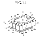
- Fig. 14 is a perspective view of a magnetic head slider 48D according to a fifth embodiment of the present invention
- Fig. 15 is a sectional view taken along line XV-XV of Fig. 14.
- the magnetic head slider 48D according to the present embodiment includes a notch 98 extending in the slider width direction, provided in the slider back surface, and a pair of slits 100 provided on the inner side with respect to the slider width direction of each of the air bearing surfaces 74.
- Each of the slits 100 extends at a predetermined distance from the air inflow end 48a and over the area from the disk faced surface to the back surface.
- Other configurations of the present embodiment are the same as in the fourth embodiment shown in Figs. 12 and 13.
- the magnetic head slider 48D has the notch 98 and the pair of slits 100, it is possible to restrict the portion where deflection is mainly desired, and to enlarge the deflection amount. Or, it is possible to obtain a desired deflection by a lower driving voltage.
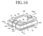
- Fig. 16 is a perspective view of a magnetic head slider 48E according to a sixth embodiment of the present invention
- Fig. 17 is a sectional view taken along line XVII-XVII of Fig. 16.
- each of the piezoelectric actuators 94a, 94b is embedded in the head slider so that the surface of each of the piezoelectric actuators 94a, 94b is flush with the head slider back surface.
- Fig. 19 is a sectional view taken along line XIX-XIX of Fig. 18.
- the piezoelectric actuator 94 is mounted on the back surface of the head slider excluding the vicinity of the air outflow end 48b.
- the piezoelectric actuator 102 is mounted over the entire area of the back surface of the slider.
- the piezoelectric actuator 102 includes an active portion (displacement portion) 102a where a plurality of electrodes 96 are embedded and an inactive portion 102b where no electrode is provided.
- the inactive portion 102b is disposed in the vicinity of the air outflow end 48b.
- the piezoelectric actuator 102 By thus mounting the piezoelectric actuator 102 on the entire area of the back surface of the slider, connection of the magnetic head slider 48F and the suspension 50 is facilitated.
- the operation of the present embodiment is the same as that of the magnetic head slider 48 according to the first embodiment described above. While the examples in which a bimorph-type piezoelectric actuator is mounted as a piezoelectric actuator have been described in the above embodiments, a monomorph-type or unimorph-type piezoelectric actuator may be mounted.
- the actuator is not limited to the piezoelectric actuator, and an electrostrictive actuator, a magnetostrictive actuator, a quartz resonator and the like may also be used for example.
- the surrounding portion of the air bearing surface on the air inflow end side is deformed by the piezoelectric actuator, whereby the balance of a positive pressure and a negative pressure exerted on the head slider can be changed, and the floating amount of the head slider can be controlled.
- the electromagnetic transducing efficiency between the electromagnetic transducer and the recording medium can be enhanced.
- the floating amount of the head slider is lowered by driving the piezoelectric actuator, whereby the reproduction output can be enhanced and reading errors can be prevented.
- the circumferential velocity is higher, and the floating amount of the head slider is greater, at the outer periphery than at the inner periphery of the recording medium.
- the positive pressure generated is reduced, whereby the floating amount of the head slider can be reduced, and therefore the floating amount can be maintained constant at the inner periphery and the outer periphery of the recording medium.
- the floating amount of the head slider is constant, recording density can be uniformized, so that zone bit recording is facilitated and recording density can be enhanced.
- the dispersion of the floating amount of the head slider due to the dispersion of the processing of the air bearing surface can be corrected. Furthermore, variation of the floating amount of the head slider according to use place (difference in height) can be corrected. By independently varying the right-side air bearing surface and the left-side air bearing surface of the front rail, the roll direction of the head slider can also be corrected. Furthermore, at the time of adhesion of the head slider onto the magnetic disk, the adhesion can be released by varying the air bearing surface by the piezoelectric actuator.
Abstract
Description
- The present invention relates to a magnetic head slider used for a magnetic disk drive.
- In recent years it has been found desirable to reduce the floating amount of a head slider for a magnetic disk drive with a view to increasing the recording density. In addition, since a high acceleration is applied in the access direction for enhancing the speed of access, there is a demand for a head slider having improved floating. Furthermore, a rotation type positioner is widely used for reducing the drive in size and simplifying mechanism, and there is a desire for a head slider with less variation of floating amount due to variation of yaw angle.
- In order to reduce the floating amount of the head slider, it is necessary to reduce the surface roughness of the magnetic disk surface. In the contact-start-stop (CSS) system widely used until now, the floating surface of the magnetic head slider and the magnetic disk make contact with each other at rotation stop times of the magnetic disk, and the magnetic head slider is floated by the action of the airflow generated attendant on the rotation of the magnetic disk at rotation times of the magnetic disk. Therefore, in the magnetic disk drive of the CSS system, if the surface roughness of the magnetic disk is reduced, the contact area between the floating surface (air bearing surface) of the magnetic disk slider and the magnetic disk surface at the rotation stop times of the magnetic disk is enlarged, so that there may be a risk of adhesion occurring between the magnetic head slider and the magnetic disk when the magnetic disk drive starts rotation.
- In the magnetic disk drive of the CSS system, in order to obviate the problem of adhesion, a technique of texturing the CSS zone of the magnetic disk by laser and a technique of providing the slider floating surface with a plurality of pads (projections) have been proposed. On the other hand, portable personal computers such as notebook-type personal computers are frequently carried and are therefore required to have high shock resistance. Therefore, a magnetic disk drive of the loading-unloading system in which the head slider is unloaded from the surface of the magnetic disk at power off times and sleep mode times and is loaded into the position above the surface of the magnetic disk at use times is generally adopted.
- In the magnetic disk drive of the loading-unloading system, a cornual (horn-shaped) portion provided at a tip end portion of a suspension is caused to ride onto a ramp (inclined portion) of a ramp member provided at an outer peripheral portion of a disk medium at power off times or sleep mode times of the computer, whereby the magnetic head slider floating above the magnetic disk with a minute gap is removed from the position above the magnetic disk. By this, it is possible to prevent the magnetic head slider from knocking on the magnetic disk, thereby damaging the magnetic disk, when a shock is exerted on the computer.
- The magnetic head slider used for the magnetic disk drive having the loading-unloading mechanism is required to have such high reliability that the contact or collision of the magnetic head slider against the magnetic disk is prevented not only when the magnetic head slider is floating above the magnetic disk but also when the magnetic head slider is loaded into the position above the magnetic disk. In order to reduce the floating gap of the magnetic head slider relative to the magnetic disk, a negative pressure magnetic head slider has been used in the recent magnetic disk drives. For example, Japanese Patent Laid-open No. 2000-173217 discloses a negative pressure head slider with low floating amount, little variation of floating amount and high rigidity.
- With a view to reducing the floating amount of the magnetic head and lowering the magnetic spacing, Japanese Patent Laid-open No. 2000-348321 discloses a technique of embedding a piezoelectric element in the back surface of the magnetic head slider as shown in Fig. 1 and Fig. 2 of the accompanying drawings. As shown in Fig. 1, the magnetic head slider has an
air inflow end 2a and anair outflow end 2b, and anelectromagnetic transducer 4 is provided in the vicinity of theair outflow end 2b. - A laminate-type
piezoelectric actuator 6 is embedded on the air outflow end side of theback surface 2c of themagnetic head slider 2. Numeral 8 denotes electrodes of thepiezoelectric actuator 6, and a voltage V is applied between theadjacent electrodes 8. As shown in Fig. 2, when the voltage V is applied between theadjacent electrodes 8, thepiezoelectric actuator 6 is displaced in the direction ofarrow 10. Numeral 11 denotes a magnetic spacing direction, and 12 denotes the transducer displacement direction. Numeral 14 denotes an air bearing surface (ABS) on the air outflow end side, and 16 denotes a recording medium. - In the
magnetic head slider 2, as shown in Fig. 2, thedisplacement direction 10 of thepiezoelectric actuator 6 is the rotational direction of therecording medium 16, and the floating amount is regulated through deflection of theslider 2 by displacement of thepiezoelectric actuator 6, so that thedisplacement direction 12 of theelectromagnetic transducer 4 is varied according to the displacement amount of thepiezoelectric actuator 6. With thepiezoelectric actuator 6 driven, theelectromagnetic transducer 4 is inclined, so that there is the problem that theelectromagnetic transducer 4 does not come to the lowermost point of theslider 2 and the floating amount is unintentionally enlarged, and there is also the problem that time variation (jitter) of recording and/or reproduction is enlarged. - In addition, elongation of the
piezoelectric actuator 6 leads to deflection of the air outflowend side ABS 14, resulting in theelectromagnetic transducer 4 being brought near to therecording medium 16. However, there is the problem that the positive pressure generated by the air outflowend side ABS 14 is enlarged and the floating amount is significantly increased. In order to solve these problems, Japanese Patent Laid-open No. 2000-348321 proposes a magnetic head slider comprising a slider main body, a piezoelectric element fixed to the slider main body, and a block having an electromagnetic transducer fixed to the piezoelectric element. However, this magnetic head slider is complicated in structure and suffers the problem that it is difficult to manufacture. - Accordingly, it is desirable to provide a head slider in which the floating amount can be arbitrarily controlled within a certain range and recording and/or reproduction characteristics can be enhanced.
- According to an embodiment of a first aspect of the present invention, there is provided a head slider having a disk faced surface, an air inflow end and an air outflow end, wherein the head slider comprises a front rail having a first air bearing surface, provided on the disk faced surface in the vicinity of the air inflow end; a transducer provided in the vicinity of the air outflow end; and a piezoelectric actuator mounted on a head slider back surface on the opposite side of the disk faced surface excluding the vicinity of the air outflow end.
- Preferably, the head slider further comprises a rear rail having a second air bearing surface, provided on the disk faced surface in the vicinity of the air outflow end. The transducer is provided at an air outflow end portion of the rear rail. Preferably, the head slider has a notch extending in the head slider width direction, provided on a head slider back surface at a portion where the piezoelectric actuator is mounted.
- In order to reduce the weight of the head slider, the piezoelectric actuator may be embedded in the head slider so that the surface of the piezoelectric actuator is flush with the back surface of the head slider. Preferably, the first air bearing surface comprises a left-side air bearing surface and a right-side air bearing surface spaced from each other, the piezoelectric actuator comprising a left-side piezoelectric actuator provided oppositely to the left-side air bearing surface, and a right-side piezoelectric actuator provided oppositely to the right-side air bearing surface.
- According to an embodiment of a second aspect of the present invention, there is provided a head slider having a disk faced surface, an air inflow end, and an air outflow end wherein the head slider comprises a front rail having a first air bearing surface, provided on the disk faced surface in the vicinity of the air inflow end; a transducer provided in the vicinity of the air outflow end; and a piezoelectric actuator mounted over the entire area of the head slider back surface on the opposite side of the disk faced surface; and the piezoelectric actuator has an inactive portion in the vicinity of the air outflow end.
- According to an embodiment of a third aspect of the present invention, there is provided a disk drive comprising: a housing having a base; a negative pressure head slider having a transducer for reading/writing data on a disk having a plurality of tracks, an air inflow end, an air outflow end, and a disk faced surface; and an actuator for moving the negative pressure head slider across the tracks of the disk, wherein the actuator comprises an actuator arm rotatably fitted to the base; a suspension whose base end is fixed to a tip end portion of the actuator arm; and the negative pressure head slider mounted on a tip end portion of the suspension; whereas the negative pressure head slider comprises a front rail having an air bearing surface, provided on the disk faced surface in the vicinity of the air inflow end; the transducer provided in the vicinity of the air outflow end; a groove for generating a negative pressure by expanding air once compressed by the front rail; and a piezoelectric actuator mounted on a head slider back surface on the opposite side of the disk faced surface excluding the vicinity of the air outflow end; and the front rail and neighboring portion are deformed in the direction toward a recording medium or away from the recording medium by the piezoelectric actuator to thereby regulate a positive pressure generated on the air bearing surface, whereby the floating amount of the head slider can be regulated.
- Reference will now be made, by way of example, to the accompanying drawings, in which:
- Fig. 1 (described above) is a perspective view of a prior art head slider;
- Fig. 2 (described above) is an illustration of operation of the prior art head slider;
- Fig. 3 is a plan view of a magnetic disk drive in the condition where a cover is removed;
- Fig. 4A is a side view of a ramp member;
- Fig. 4B is a plan view of the ramp member;
- Fig. 5 is a perspective view of a first embodiment of the present invention;
- Fig. 6 is a sectional view taken along line VI-VI of Fig. 5;
- Fig. 7 is an illustration of operation of a magnetic head slider according to the first embodiment;
- Fig. 8 is a perspective view of a second embodiment of the present invention;
- Fig. 9 is a sectional view taken along line IX-IX of Fig. 8;
- Fig. 10 is a perspective view of a third embodiment of the present invention;
- Fig. 11 is a sectional view taken along line XI-XI of Fig. 10;
- Fig. 12 is a perspective view of a fourth embodiment of the present invention;
- Fig. 13 is a sectional view taken along line XIII-XIII of Fig. 12;
- Fig. 14 is a perspective view of a fifth embodiment of the present invention;
- Fig. 15 is a sectional view taken along line XV-XV of Fig. 14;
- Fig. 16 is a perspective view of a sixth embodiment of the present invention;
- Fig. 17 is a sectional view taken along line XVII-XVII of Fig. 16;
- Fig. 18 is a perspective view of a seventh embodiment of the present invention; and
- Fig. 19 is a sectional view taken along line XIX-XIX of Fig. 18.
-
- Referring to Fig. 3, there is shown a plan view of a magnetic disk drive in the condition where a cover is removed. A
housing 22 is composed of abase 24 and a cover (not shown) fixed to thebase 24. Ashaft 26 is fixed to thebase 24, and a spindle hub (not shown) driven to rotate by a DC motor is provided in the surrounding of theshaft 26.Magnetic disks 28 and spacers (not shown) are alternatingly fitted over the spindle hub, and adisk clamp 30 is fastened to the spindle hub by a plurality ofscrews 32, whereby a plurality of themagnetic disks 28 are fitted to the spindle hub at predetermined spacings. - Numeral 34 denotes a rotary actuator composed of an
actuator arm assembly 36 and amagnetic circuit 38. Theactuator arm assembly 36 is rotatably mounted to ashaft 40 fixed to thebase 24. Theactuator arm assembly 36 comprises an actuator block 42 rotatably mounted to theshaft 40 through a pair of bearings, a plurality ofactuator arms 44 extended in one direction from the actuator block 42, andhead assemblies 46 each fixed to a tip end portion of each of theactuator arms 44. Each of thehead assemblies 46 comprises ahead slider 48 having a magnetic head element (transducer) for writing/reading data on themagnetic disk 28, and a suspension (load beam) 50 which supports thehead slider 48 at its tip end portion and has a base end portion fixed to theactuator arm 44. - A
coil 51 is supported on the opposite side of theactuator arm 44 with respect to theshaft 40, and thecoil 51 is inserted into the gap of themagnetic circuit 38, thereby constituting a voice coil motor (VCM) 52.Numeral 54 denotes a flexible printed circuit board (FPC) for supplying a writing signal to the transducer and picking up a reading signal from the transducer, and one end thereof is fixed to a side surface of the actuator block 42. - A
ramp member 56 is fixed to thebase 24 adjacently to the outer periphery of themagnetic disk 28. As shown in Figs. 4A and 4B, theramp member 56 comprises a plurality of ramps (inclined portions) 60 corresponding to the number of the sliders, and a plurality ofparking portions 62 on whichcornual portions 66 provided at the tip ends of thehead assemblies 46 are stably parked.Projections 64 for preventing the unloaded head sliders from interfering with each other are provided on a side surface of theramp member 56.Numeral 58 denotes a latch mechanism for latching aprojection portion 59 of theactuator 34 in an unloaded condition. - The condition shown is the unloaded condition where the
head slider 48 is unloaded from the position above themagnetic disk 28, thecornual portion 66 of thehead assembly 46 is parked on theparking portions 62 of theramp member 56, and theprojection portion 59 of theactuator 34 is latched by thelatch mechanism 58. When a power source for the computer is turned ON or a sleep mode is released under this condition, thelatch mechanism 58 is first released, theactuator 34 is rotated counterclockwise, and thecornual portion 66 slides down theramp 60, whereby thehead slider 48 is loaded into the position above themagnetic disk 28. - When the power source for the computer is turned OFF or the sleep mode is started, a control means such as an MPU mounted on a main printed wiring board of the magnetic disk drive which is not shown controls the
actuator 34 so that each of thehead sliders 48 is rotated beyond the outer periphery of themagnetic disk 28. By this, thecornual portion 66 of thehead assembly 46 climes up theramp 60 of theramp member 56, to park in aparking position 62. In this condition, theprojection portion 59 of theactuator 34 is latched by thelatch mechanism 58. - Referring to Fig. 5, there is shown a perspective view of a negative pressure
magnetic head slider 48 according to a first embodiment of the present invention. Fig. 6 is a sectional view taken along line VI-VI of Fig. 5. Themagnetic head slider 48 is rectangular parallelepiped in shape, and has anair inflow end 48a and anair outflow end 48b. Themagnetic head slider 48 is sized, for example, 1.25 mm by 1 mm and 0.3 mm in thickness. The material of themagnetic head slider 48 is Al2O3-TiC, and themagnetic head slider 48 is produced by forming a multiplicity of electromagnetic transducing elements (electromagnetic transducers) on a wafer, cutting the wafer into the shape of bars, and processing side surfaces of the bars to provide rail surfaces. The formation of the rail surfaces is carried out by using a photolithography technology. - The
magnetic head slider 48 is a negative pressure magnetic head slider, and comprises afront rail 70 provided on the side of theair inflow end 48a, and arear center rail 72 provided on the side of theair outflow end 48b. Thefront rail 70 is provided at its top surface with an air bearing surface (ABS) 74, and astep surface 76 lower than theair bearing surface 74 by a predetermined step. Similarly, therear center rail 72 is provided with anair bearing surface 78, and astep surface 80 lower than theair bearing surface 78 by a predetermined step. Anelectromagnetic transducing element 82 is provided at an air outflow end portion of therear center rail 72. - A pair of side rails 84, 86 extending to the downstream side are provided on both sides in the slider width direction of the
front rail 70. Top faces 88, 90 of the side rails 84, 86 are at the same height as thestep surface 76 of thefront rail 70. Agroove 92 is provided on the downstream side of thefront rail 70. The depth of thegroove 92 from theair bearing surface 74 is about 1.4 µm, and the step between theair bearing surface 74 and thestep surface 76 is about 0.2 µm. Similarly, the step between theair bearing surface 78 and thestep surface 80 of therear center rail 72 is about 0.2 µm. - A
piezoelectric actuator 94 is mounted on the back surface of the head slider excluding the vicinity of theair outflow end 48b. Thepiezoelectric actuator 94 is composed, for example, of lead zirconate titanate (PZT). A plurality of green sheets of PZT are laminated, a plurality ofelectrodes 96 are embedded between the green sheets, and the green sheets are integrally adhered by compressing while heating. Then, the integrally laminated green sheets are fired, whereby thepiezoelectric actuator 94 is produced. - When a voltage V is applied between the
adjacent electrodes 96, thepiezoelectric actuator 94 is contracted in the direction ofarrow 95 orthogonal to the driving electric field. When a voltage -V is applied between theadjacent electrodes 96, thepiezoelectric actuator 94 is extended in the direction opposite toarrow 95. Thepiezoelectric actuator 94 is a bimorph-type piezoelectric actuator. Thepiezoelectric actuator 94 can also be produced by use of barium titanate (BaTiO3), lead titanate (PbTiO3) or the like, in place of PZT. - The
magnetic head slider 48 is mounted to thesuspension 50 at its back surface. When the magnetic disk is rotated and an airflow is generated along the disk surface, the airflow collides against the step between theair bearing surface 74 and thestep surface 76 and the step between theair bearing surface 78 and thestep surface 80, and then acts on the air bearing surfaces 74, 78. As a result, a buoyancy for floating themagnetic head slider 48 from the disk surface is generated at the air bearing surfaces 74, 78. A buoyancy is also generated at the step surfaces 76, 80, but it is not so large. In thismagnetic head slider 48, a large buoyancy is generated at theair bearing surface 74 and, as a result, themagnetic head slider 48 is maintained in an inclined posture with a pitch angle α at the time of floating. Here, the pitch angle α is the inclination angle of themagnetic head slider 48 along the flow line of the airflow. - Since the
groove 92 is provided on the downstream side of thefront rail 70, the airflow passing along theair bearing surface 74 spreads in the direction perpendicular to the disk surface at the portion of thegroove 92 simultaneously when passing through thefront rail 70, and, as a result, a negative pressure is generated at the portion of thegroove 92. The negative pressure balances with the above-mentioned buoyancy (positive pressure), whereby the floating amount of themagnetic head slider 48 is determined. Furthermore, in themagnetic head slider 48 according to the present embodiment, thepiezoelectric actuator 94 is mounted on the back surface of themagnetic head slider 48. When a voltage V is applied between theadjacent electrodes 96 of thepiezoelectric actuator 94, therefore, thepiezoelectric actuator 94 contracts in the direction ofarrow 95 in Fig. 5, resulting in that themagnetic head slider 48 is deformed as indicated by broken line in Fig. 7. - With the
magnetic head slider 48 deformed in this manner, the positive pressure generated at the front-side air bearing surface (front ABS) 74 is reduced, and the floating amount of themagnetic head slider 48 is reduced. Therefore, the magnetic spacing between theelectromagnetic transducing element 82 and therecording medium 28 is reduced, so that reproduction output of theelectromagnetic transducing element 82 can be enhanced. When a voltage of -V is applied between theadjacent electrodes 96 of thepiezoelectric actuator 94, thepiezoelectric actuator 94 extends in the direction opposite toarrow 95, so that themagnetic head slider 48 is deflected in the direction opposite to the deflection direction indicated by broken line, namely, deflected to the side of therecording medium 28. As a result, the positive pressure generated at thefront ABS 74 is increased, and the floating amount of themagnetic head slider 48 is enlarged. Thus, in themagnetic head slider 48 according to the present embodiment, the floating amount of themagnetic head slider 48 is controlled by regulating the positive pressure (a pressure for floating theslider 48 from the recording medium 28) generated mainly at thefront ABS 74. - Since the circumferential velocity is greater on the outer periphery side than the inner periphery side of the recording medium (magnetic disk) 28, the floating amount of the
magnetic head slider 48 is greater on the outer periphery side. Therefore, when thefront ABS 74 is displaced away from therecording medium 28 by thepiezoelectric actuator 94 as the outer periphery is approached, the positive pressure generated is reduced to reduce the floating amount, whereby the floating amount can be maintained constant at the inner periphery and the outer periphery. Where the floating amount of themagnetic head slider 48 is constant, recording density can be uniformized. Therefore, zone bit recording becomes easy, and recording density can be enhanced. Also where the reproduction output of theelectromagnetic transducing element 82 is low and reading errors are liable to be generated, the floating amount of themagnetic head slider 48 is reduced by driving thepiezoelectric actuator 94, whereby the reproduction output is enhanced, and reading errors can be prevented. - Fig. 8 is a perspective view of a
magnetic head slider 48A according to a second embodiment of the present invention, and Fig. 9 is a sectional view taken along line IX-IX of Fig. 8. In themagnetic head slider 48A according to this embodiment, a head slider back surface at the portion where thepiezoelectric actuator 94 is mounted is provided with anotch 98 extending in the slider width direction. Other configurations of the present embodiment are the same as in the first embodiment shown in Figs. 5 and 6. Thus, by providing the slider back surface with thenotch 98, it is possible to restrict the portion where deflection is mainly desired, and to enlarge the deflection amount. Or, it is possible to obtain a desired deflection amount by a lower voltage. - Fig. 10 is a perspective view of a
magnetic head slider 48B according to a third embodiment of the present invention, and Fig. 11 is a sectional view taken along line XI-XI of Fig. 10. In themagnetic head slider 48B according to the present embodiment, thepiezoelectric actuator 94 is embedded in thehead slider 48B so that the surface of thepiezoelectric actuator 94 is flush with the head slider back surface. By this, the increase in mass of themagnetic head slider 48B due to the mounting of thepiezoelectric actuator 94 can be suppressed. - Referring to Fig. 12, there is shown a perspective view of a
magnetic head slider 48C according to a fourth embodiment of the present invention. Fig. 13 is a sectional view taken along line XIII-XIII of Fig. 12. In themagnetic head slider 48C according to the present embodiment, twopiezoelectric actuators side piezoelectric actuator 94a is provided opposite to the left-sideair bearing surface 74, and the right-side piezoelectric actuator 94b is provided opposite to the right-sideair bearing surface 74. - In the same manner as in the first to third embodiments described above, each of the
piezoelectric actuators electrodes 96, and by applying a predetermined voltage between the adjacent electrodes, thepiezoelectric actuators piezoelectric actuators individual front ABSs 74, there is a difference in deflection amount in the surroundings of theindividual front ABSs 74, whereby it is possible to control in the roll direction of themagnetic head slider 48C, and to control the floating posture more finely. - Fig. 14 is a perspective view of a
magnetic head slider 48D according to a fifth embodiment of the present invention, and Fig. 15 is a sectional view taken along line XV-XV of Fig. 14. Themagnetic head slider 48D according to the present embodiment includes anotch 98 extending in the slider width direction, provided in the slider back surface, and a pair ofslits 100 provided on the inner side with respect to the slider width direction of each of the air bearing surfaces 74. Each of theslits 100 extends at a predetermined distance from theair inflow end 48a and over the area from the disk faced surface to the back surface. Other configurations of the present embodiment are the same as in the fourth embodiment shown in Figs. 12 and 13. Since themagnetic head slider 48D according to the present embodiment has thenotch 98 and the pair ofslits 100, it is possible to restrict the portion where deflection is mainly desired, and to enlarge the deflection amount. Or, it is possible to obtain a desired deflection by a lower driving voltage. - Fig. 16 is a perspective view of a
magnetic head slider 48E according to a sixth embodiment of the present invention, and Fig. 17 is a sectional view taken along line XVII-XVII of Fig. 16. In themagnetic head slider 48E according to the present embodiment, in the same manner as in themagnetic head slider 48B according to the third embodiment shown in Figs. 10 and 11, each of thepiezoelectric actuators piezoelectric actuators piezoelectric actuators magnetic head slider 48E due to the mounting of thepiezoelectric actuators - Referring to Fig. 18, there is shown a perspective view of a
magnetic head slider 48F according to a seventh embodiment of the present invention. Fig. 19 is a sectional view taken along line XIX-XIX of Fig. 18. In the first to sixth embodiments described above, thepiezoelectric actuator 94 is mounted on the back surface of the head slider excluding the vicinity of theair outflow end 48b. In themagnetic head slider 48F according to the present embodiment, thepiezoelectric actuator 102 is mounted over the entire area of the back surface of the slider. Thepiezoelectric actuator 102 includes an active portion (displacement portion) 102a where a plurality ofelectrodes 96 are embedded and aninactive portion 102b where no electrode is provided. Theinactive portion 102b is disposed in the vicinity of theair outflow end 48b. - By thus mounting the
piezoelectric actuator 102 on the entire area of the back surface of the slider, connection of themagnetic head slider 48F and thesuspension 50 is facilitated. The operation of the present embodiment is the same as that of themagnetic head slider 48 according to the first embodiment described above. While the examples in which a bimorph-type piezoelectric actuator is mounted as a piezoelectric actuator have been described in the above embodiments, a monomorph-type or unimorph-type piezoelectric actuator may be mounted. Furthermore, the actuator is not limited to the piezoelectric actuator, and an electrostrictive actuator, a magnetostrictive actuator, a quartz resonator and the like may also be used for example. - According to an embodiment of the present invention, as has been detailed above, the surrounding portion of the air bearing surface on the air inflow end side is deformed by the piezoelectric actuator, whereby the balance of a positive pressure and a negative pressure exerted on the head slider can be changed, and the floating amount of the head slider can be controlled. By so controlling as to reduce the floating amount, the electromagnetic transducing efficiency between the electromagnetic transducer and the recording medium can be enhanced. Attendant on this, even where the reproduction output of the electromagnetic transducer is low and reading errors are liable to be generated, the floating amount of the head slider is lowered by driving the piezoelectric actuator, whereby the reproduction output can be enhanced and reading errors can be prevented.
- In addition, the circumferential velocity is higher, and the floating amount of the head slider is greater, at the outer periphery than at the inner periphery of the recording medium. Thus, by displacing the front-side air bearing surface in the direction away from the recording medium by the piezoelectric actuator as the outer periphery is approached, the positive pressure generated is reduced, whereby the floating amount of the head slider can be reduced, and therefore the floating amount can be maintained constant at the inner periphery and the outer periphery of the recording medium. Where the floating amount of the head slider is constant, recording density can be uniformized, so that zone bit recording is facilitated and recording density can be enhanced.
- The dispersion of the floating amount of the head slider due to the dispersion of the processing of the air bearing surface can be corrected. Furthermore, variation of the floating amount of the head slider according to use place (difference in height) can be corrected. By independently varying the right-side air bearing surface and the left-side air bearing surface of the front rail, the roll direction of the head slider can also be corrected. Furthermore, at the time of adhesion of the head slider onto the magnetic disk, the adhesion can be released by varying the air bearing surface by the piezoelectric actuator.
Claims (11)
- A head slider having a disk faced surface, an air inflow end, and an air outflow end, said head slider comprising:a front rail having a first air bearing surface, provided on the disk faced surface in the vicinity of the air inflow end;a transducer provided in the vicinity of the air outflow end; anda piezoelectric actuator mounted on a head slider back surface on the opposite side of the disk faced surface excluding the vicinity of the air outflow end.
- A head slider as set forth in claim 1, wherein said piezoelectric actuator is embedded in said head slider so that the surface of said piezoelectric actuator is flush with the back surface of said head slider.
- A head slider as set forth in claim 1 or 2, wherein
said first air bearing surface comprises a left-side air bearing surface and a right-side air bearing surface spaced from each other, and
said piezoelectric actuator comprises a left-side piezoelectric actuator provided opposite to said left-side air bearing surface, and a right-side piezoelectric actuator provided opposite to said right-side air bearing surface. - A head slider as set forth in any preceding claim, further comprising a notch extending in a head slider width direction, provided in the back surface of said head slider at a portion where said piezoelectric actuator is mounted.
- A head slider as set forth in claim 3, or claim 4 when read as appended to claim 3, further comprising:a first slit provided over the range from the disk faced surface to the slider back surface in a predetermined length from the air inflow end on the inner side with respect to the width direction of said left-side air bearing surface, anda second slit provided over the range from the disk faced surface to the slider back surface in a predetermined length from the air inflow end on the inner side with respect to the width direction of said right-side air bearing surface.
- A head slider as set forth in claim 3 or 5, or claim 4 when read as appended to claim 3, wherein said left-side and right-side piezoelectric actuators are embedded in said head slider so that the surface of said left-side piezoelectric actuator and the surface of said right-side piezoelectric actuator are flush with the slider back surface.
- A head slider having a disk faced surface, an air inflow end, and an air outflow end, said head slider comprising:a front rail having a first air bearing surface, provided on the disk faced surface in the vicinity of the air inflow end;a transducer provided in the vicinity of the air outflow end; anda piezoelectric actuator mounted over the entire area of the head slider back surface on the opposite side of the disk faced surface, said piezoelectric actuator having an inactive portion in the vicinity of the air outflow end.
- A head slider as set forth in any preceding claim, further comprising a rear rail having a second air bearing surface, provided on the disk faced surface in the vicinity of the air outflow end, wherein
said transducer is provided at an air outflow end portion of said rear rail. - A head slider having a disk faced surface, an air inflow end, and an air outflow end, said head slider comprising:wherein the center in the longitudinal direction of said piezoelectric actuator is located on the air inflow end side with respect to the center in the longitudinal direction of said head slider.a front rail having a first air bearing surface, provided on the disk faced surface in the vicinity of the air inflow end;a transducer provided in the vicinity of the air outflow end; anda piezoelectric actuator mounted on a head slider back surface on the opposite side of the disk faced surface;
- A head slider as set forth in claim 9, wherein L1 > L2, where L1 is a length from the center in the longitudinal direction of said head slider to the air inflow end portion of said piezoelectric actuator, and L2 is a length from the center in the longitudinal direction of said head slider to the air outflow end portion of said piezoelectric actuator.
- A disk drive comprising:a housing having a base;a negative pressure head slider having a transducer for reading/writing data on a disk having a plurality of tracks, an air inflow end, an air outflow end, and a disk faced surface; andan actuator for moving said negative pressure head slider across the tracks of the disk;said actuator comprising:actuator arm rotatably mounted on the base;a suspension having a base end portion fixed to a tip end portion of said actuator arm; andsaid negative pressure head slider mounted on a tip end portion of said suspension;said negative pressure head slider comprising:a front rail having an air bearing surface, provided on the disk faced surface in the vicinity of the air inflow end;said transducer provided in the vicinity of the air outflow end;a groove for generating a negative pressure by expanding air once compressed by said front rail; anda piezoelectric actuator mounted on the head slider back surface on the opposite side of the disk faced surface excluding the vicinity of the air outflow end;said front rail and neighboring portion thereof being deformed toward a recording medium or away from the recording medium by said piezoelectric actuator to thereby regulate a positive pressure generated at the air bearing surface, whereby the floating amount of said head slider can be regulated.
Applications Claiming Priority (2)
| Application Number | Priority Date | Filing Date | Title |
|---|---|---|---|
| JP2001351316A JP3917409B2 (en) | 2001-11-16 | 2001-11-16 | Head slider and disk device |
| JP2001351316 | 2001-11-16 |
Publications (2)
| Publication Number | Publication Date |
|---|---|
| EP1315151A2 true EP1315151A2 (en) | 2003-05-28 |
| EP1315151A3 EP1315151A3 (en) | 2006-12-20 |
Family
ID=19163643
Family Applications (1)
| Application Number | Title | Priority Date | Filing Date |
|---|---|---|---|
| EP02251561A Withdrawn EP1315151A3 (en) | 2001-11-16 | 2002-03-06 | Magnetic head slider |
Country Status (5)
| Country | Link |
|---|---|
| US (1) | US6870709B2 (en) |
| EP (1) | EP1315151A3 (en) |
| JP (1) | JP3917409B2 (en) |
| KR (1) | KR100773840B1 (en) |
| CN (1) | CN1240054C (en) |
Cited By (2)
| Publication number | Priority date | Publication date | Assignee | Title |
|---|---|---|---|---|
| EP1898398A1 (en) | 2006-09-07 | 2008-03-12 | Hitachi Global Storage Technologies B. V. | Head slider |
| US7423843B2 (en) | 2003-09-02 | 2008-09-09 | Kabushiki Kaisha Toshiba | In-contact magnetic head slider with multiple surface levels for creating multiple positive and negative pressure regions |
Families Citing this family (36)
| Publication number | Priority date | Publication date | Assignee | Title |
|---|---|---|---|---|
| WO2003041062A1 (en) * | 2001-11-03 | 2003-05-15 | Sae Magnetics (H.K.) Ltd. | Method and apparatus for improved attachment of a micro-actuator to a slider device |
| JP3696596B2 (en) * | 2003-02-07 | 2005-09-21 | アルプス電気株式会社 | Magnetic head actuator and manufacturing method thereof |
| US7248442B1 (en) * | 2003-03-05 | 2007-07-24 | Meyer Dallas W | Integrated recording head micropositioner using off-axis flexure bending |
| US7369369B1 (en) | 2003-04-03 | 2008-05-06 | Meyer Dallas W | Bidirectional micropositioning recording head for a magnetic storage device |
| US6992865B2 (en) * | 2003-06-19 | 2006-01-31 | Seagate Technology Llc | Headstack with semi-permanently deformable element for pole-tip recession adjustment |
| JP4198557B2 (en) * | 2003-07-15 | 2008-12-17 | 富士通株式会社 | Head slider and magnetic disk apparatus having the head slider |
| US7538983B1 (en) * | 2003-07-29 | 2009-05-26 | Meyer Dallas W | Micropositioner recording head for a magnetic storage device |
| US20060262455A1 (en) * | 2003-08-29 | 2006-11-23 | Druist David P | Apparatus and method for forming a magnetic head coil in a compact area using damascene technology |
| US7072136B2 (en) * | 2003-09-25 | 2006-07-04 | Hitachi Global Storage Technologies Netherlands B.V. | Method and apparatus for dynamically establishing pitch static attitude in hard disk drive |
| JP2005228362A (en) * | 2004-02-10 | 2005-08-25 | Matsushita Electric Ind Co Ltd | Slider and magnetic disk unit |
| JP4146811B2 (en) * | 2004-03-03 | 2008-09-10 | Tdk株式会社 | Suspension and hard disk device |
| JP4268904B2 (en) * | 2004-06-11 | 2009-05-27 | 富士通株式会社 | Disk device and slider |
| US7646566B1 (en) | 2004-08-05 | 2010-01-12 | Maxtor Corporation | Slider deformation control by thermal-structural compensators |
| US7773346B1 (en) * | 2005-08-19 | 2010-08-10 | Seagate Technology Llc | Slider that dynamically adjusts the head-to-disk spacing in a disk drive |
| US8756776B1 (en) | 2005-12-09 | 2014-06-24 | Western Digital Technologies, Inc. | Method for manufacturing a disk drive microactuator that includes a piezoelectric element and a peripheral encapsulation layer |
| JP2007293948A (en) * | 2006-04-21 | 2007-11-08 | Fujitsu Ltd | Information recording and reproducing device, head floating height control method, head floating control circuit |
| US20070297080A1 (en) * | 2006-06-23 | 2007-12-27 | Lee Sungchang | Apparatus and method for bending a slider to create rounded corners on its trailing edge in a hard disk drive |
| JP2008059660A (en) * | 2006-08-30 | 2008-03-13 | Fujitsu Ltd | Head slider |
| JP2008084412A (en) * | 2006-09-27 | 2008-04-10 | Fujitsu Ltd | Storage medium drive unit and head slider |
| US7837885B2 (en) * | 2006-11-07 | 2010-11-23 | Sae Magnetics (Hk) Ltd. | Air bearing design with a flatter pitch profile for reducing particle TAs |
| US7948713B2 (en) * | 2007-01-12 | 2011-05-24 | Tdk Corporation | Magnetic head slider using giant magnetostrictive material |
| US8040639B2 (en) * | 2007-03-28 | 2011-10-18 | Hitachi Global Storage Technologies, Netherlands B.V. | Integrated silicon micro-actuator slider |
| JP2009110563A (en) * | 2007-10-26 | 2009-05-21 | Hitachi Global Storage Technologies Netherlands Bv | Disk drive and head slider |
| US8643980B1 (en) | 2008-12-15 | 2014-02-04 | Western Digital (Fremont), Llc | Micro-actuator enabling single direction motion of a magnetic disk drive head |
| US8279559B1 (en) | 2009-01-02 | 2012-10-02 | Meyer Dallas W | Process for creating discrete track magnetic recording media including an apparatus having a stylus selectively applying stress to a surface of the recording media |
| US8264797B2 (en) * | 2009-12-21 | 2012-09-11 | Western Digital (Fremont), Llc | Head gimbal assembly having a radial rotary piezoelectric microactuator between a read head and a flexure tongue |
| US8792212B1 (en) | 2010-09-14 | 2014-07-29 | Western Digital (Fremont), Llc | Robust gimbal design for head gimbal assembly |
| US8295012B1 (en) | 2011-06-14 | 2012-10-23 | Western Digital Technologies, Inc. | Disk drive suspension assembly with rotary fine actuator at flexure tongue |
| US8593764B1 (en) | 2011-06-14 | 2013-11-26 | Western Digital Technologies, Inc. | Method for fine actuation of a head during operation of a disk drive |
| US8446694B1 (en) | 2011-06-14 | 2013-05-21 | Western Digital Technologies, Inc. | Disk drive head suspension assembly with embedded in-plane actuator at flexure tongue |
| US9318031B2 (en) * | 2012-08-27 | 2016-04-19 | Michael Edward Boyd | Device and method to produce gravitomagnetic induction, mass spin-valve or gravitational rectifier |
| US8810971B1 (en) | 2013-04-08 | 2014-08-19 | HGST Netherlands B.V. | Single sheet differential-poled piezoelectric microactuator for a hard disk drive |
| US8797691B1 (en) | 2013-05-21 | 2014-08-05 | Western Digital Technologies, Inc. | Disk drive head suspension with a single piezoelectric element adhered to rotary-actuated and non-actuated portions of a structural layer of a tongue of a laminated flexure |
| US8982513B1 (en) | 2013-05-21 | 2015-03-17 | Western Digital Technologies, Inc. | Disk drive head suspension with dual piezoelectric elements adhered to rotary-actuated and non-actuated portions of a structural layer of a tongue of a laminated flexure |
| US10210889B1 (en) * | 2017-09-29 | 2019-02-19 | Seagate Technology Llc | Monolithically-integrated hybridized slider electronics for magnetic read/write |
| IT201900022488A1 (en) * | 2019-11-29 | 2021-05-29 | St Microelectronics Srl | READING / WRITING DEVICE FOR A HARD DISK MEMORY SYSTEM AND ITS MANUFACTURING PROCEDURE |
Citations (3)
| Publication number | Priority date | Publication date | Assignee | Title |
|---|---|---|---|---|
| EP0435916A1 (en) * | 1988-09-22 | 1991-07-10 | Harvey Bailey Eng Ltd | Control arrangement. |
| US5943189A (en) * | 1996-12-05 | 1999-08-24 | Seagate Technology, Inc. | Piezoelectric engageable slider and slider microactuator |
| JP2000348321A (en) | 1999-06-03 | 2000-12-15 | Nec Corp | Magnetic disk device, magnetic head, manufacture of magnetic head, and manufacture of magnetic disk device |
Family Cites Families (14)
| Publication number | Priority date | Publication date | Assignee | Title |
|---|---|---|---|---|
| US4605977A (en) * | 1983-12-14 | 1986-08-12 | Sperry Corporation | Air bearing head displacement sensor and positioner |
| US4532802A (en) * | 1984-05-31 | 1985-08-06 | International Business Machines Corporation | Apparatus for analyzing the interface between a recording disk and a read-write head |
| US5021906A (en) * | 1989-10-31 | 1991-06-04 | International Business Machines Corporation | Programmable air bearing slider including magnetic read/write element |
| US5777825A (en) * | 1996-09-04 | 1998-07-07 | International Business Machines Corporation | Negative pressure step pad air bearing design and method for making the same |
| KR100287567B1 (en) * | 1996-10-31 | 2001-04-16 | 사토 히로시 | Read / write heads, read / write head positioning mechanisms, and read / write systems |
| US6327120B1 (en) * | 1997-04-17 | 2001-12-04 | Fujitsu Limited | Actuator using piezoelectric element and head-positioning mechanism using the actuator |
| US6314799B1 (en) * | 1997-07-25 | 2001-11-13 | Seagate Technology, Llc | Advanced glidehead sensor for small slider |
| US6239947B1 (en) * | 1998-05-11 | 2001-05-29 | International Business Machines Corporation | Milliactuator with integrated sensor and drivers and method of manufacturing the same |
| KR100601607B1 (en) * | 1999-06-02 | 2006-07-14 | 삼성전자주식회사 | Head suspension assembly of disk drive |
| US6338269B1 (en) * | 2000-03-09 | 2002-01-15 | Marburg Technologies, Inc. | Glide head with side mounted transducer |
| US6435016B1 (en) * | 2000-03-24 | 2002-08-20 | Saint-Gobain Ceramics & Plastics, Inc. | Head gimbal assembly, test device and slider for use therewith |
| US6624984B2 (en) * | 2000-05-25 | 2003-09-23 | Seagate Technology Llc | Fly height control slider with crown and cross curve de-coupling |
| JP3689635B2 (en) * | 2000-11-15 | 2005-08-31 | 株式会社日立グローバルストレージテクノロジーズ | Magnetic disk unit |
| US6611399B1 (en) * | 2000-12-07 | 2003-08-26 | Seagate Technology Llc | Micro-actuated micro-suspension(MAMS) slider for both fly height and tracking position |
-
2001
- 2001-11-16 JP JP2001351316A patent/JP3917409B2/en not_active Expired - Fee Related
-
2002
- 2002-03-06 EP EP02251561A patent/EP1315151A3/en not_active Withdrawn
- 2002-03-12 KR KR1020020013308A patent/KR100773840B1/en not_active IP Right Cessation
- 2002-03-19 US US10/101,009 patent/US6870709B2/en not_active Expired - Fee Related
- 2002-04-10 CN CNB021063001A patent/CN1240054C/en not_active Expired - Fee Related
Patent Citations (3)
| Publication number | Priority date | Publication date | Assignee | Title |
|---|---|---|---|---|
| EP0435916A1 (en) * | 1988-09-22 | 1991-07-10 | Harvey Bailey Eng Ltd | Control arrangement. |
| US5943189A (en) * | 1996-12-05 | 1999-08-24 | Seagate Technology, Inc. | Piezoelectric engageable slider and slider microactuator |
| JP2000348321A (en) | 1999-06-03 | 2000-12-15 | Nec Corp | Magnetic disk device, magnetic head, manufacture of magnetic head, and manufacture of magnetic disk device |
Cited By (2)
| Publication number | Priority date | Publication date | Assignee | Title |
|---|---|---|---|---|
| US7423843B2 (en) | 2003-09-02 | 2008-09-09 | Kabushiki Kaisha Toshiba | In-contact magnetic head slider with multiple surface levels for creating multiple positive and negative pressure regions |
| EP1898398A1 (en) | 2006-09-07 | 2008-03-12 | Hitachi Global Storage Technologies B. V. | Head slider |
Also Published As
| Publication number | Publication date |
|---|---|
| KR100773840B1 (en) | 2007-11-06 |
| KR20030039984A (en) | 2003-05-22 |
| JP2003157637A (en) | 2003-05-30 |
| US6870709B2 (en) | 2005-03-22 |
| CN1420490A (en) | 2003-05-28 |
| EP1315151A3 (en) | 2006-12-20 |
| US20030095361A1 (en) | 2003-05-22 |
| JP3917409B2 (en) | 2007-05-23 |
| CN1240054C (en) | 2006-02-01 |
Similar Documents
| Publication | Publication Date | Title |
|---|---|---|
| US6870709B2 (en) | Head slider having piezoelectric actuator | |
| US6246552B1 (en) | Read/write head including displacement generating means that elongates and contracts by inverse piezoelectric effect of electrostrictive effect | |
| US5021906A (en) | Programmable air bearing slider including magnetic read/write element | |
| US6617763B2 (en) | Piezoelectric actuator set for head assembly | |
| US7023667B2 (en) | Dual stage suspension with PZT actuators arranged to improve actuation in suspensions of short length | |
| US8593764B1 (en) | Method for fine actuation of a head during operation of a disk drive | |
| US8213127B2 (en) | Microactuator, head gimbal assembly, and magnetic disk drive | |
| US20020105750A1 (en) | Microactuator for dynamic controlling head-media interaction and fly-height | |
| US6683755B2 (en) | Negative pressure type head slider and disk drive employing same | |
| JP3689635B2 (en) | Magnetic disk unit | |
| US7061724B2 (en) | Disc drive magnetic head fine positioning mechanism including a base connecting a suspension to an arm, and having a piezoelectric drive element adjacent thereto | |
| US7859794B2 (en) | Magnetic head slider and magnetic disk drive | |
| JP2005078753A (en) | Flexure, suspension, and head gimbals assembly | |
| US20070070552A1 (en) | Micro-actuator and head gimbal assembly for a disk drive device | |
| JP4038437B2 (en) | Magnetic head slider and magnetic disk apparatus | |
| JP4231004B2 (en) | Magnetic disk unit | |
| US6667855B2 (en) | Disk drive capable of avoiding the contact of disk and head slider in loading | |
| JPH11273041A (en) | Magnetic disk device and recording and reproducing method | |
| US6680820B2 (en) | Method of maintaining a constant flying height of a magnetic head and a magnetic disk drive utilized therefor | |
| KR100258937B1 (en) | Magnetic head slider for hard disk drive | |
| JPH09265617A (en) | Magnetic head suspension and magnetic recorder | |
| JP3947488B2 (en) | Actuator and slider unit | |
| JP2005028554A (en) | Fine motion actuator and recording medium drive device | |
| JPWO2007132516A1 (en) | Recording medium driving device and head suspension assembly | |
| JP2003257008A (en) | Rotary head and magnetic recording/reproducing device |
Legal Events
| Date | Code | Title | Description |
|---|---|---|---|
| PUAI | Public reference made under article 153(3) epc to a published international application that has entered the european phase |
Free format text: ORIGINAL CODE: 0009012 |
|
| AK | Designated contracting states |
Designated state(s): AT BE CH CY DE DK ES FI FR GB GR IE IT LI LU MC NL PT SE TR |
|
| AX | Request for extension of the european patent |
Extension state: AL LT LV MK RO SI |
|
| PUAL | Search report despatched |
Free format text: ORIGINAL CODE: 0009013 |
|
| AK | Designated contracting states |
Kind code of ref document: A3 Designated state(s): AT BE CH CY DE DK ES FI FR GB GR IE IT LI LU MC NL PT SE TR |
|
| AX | Request for extension of the european patent |
Extension state: AL LT LV MK RO SI |
|
| RIC1 | Information provided on ipc code assigned before grant |
Ipc: G11B 5/54 20060101ALI20061115BHEP Ipc: G11B 5/60 20060101AFI20030214BHEP |
|
| 17P | Request for examination filed |
Effective date: 20070312 |
|
| AKX | Designation fees paid |
Designated state(s): DE FR GB |
|
| 17Q | First examination report despatched |
Effective date: 20090227 |
|
| RAP1 | Party data changed (applicant data changed or rights of an application transferred) |
Owner name: TOSHIBA STORAGE DEVICE CORPORATION |
|
| STAA | Information on the status of an ep patent application or granted ep patent |
Free format text: STATUS: THE APPLICATION IS DEEMED TO BE WITHDRAWN |
|
| 18D | Application deemed to be withdrawn |
Effective date: 20111001 |